Article

Performance Enhancement of Ti/IrO2-Ta2O5 Anode through Introduction of Tantalum–Titanium Interlayer via Double-Glow Plasma Surface Alloying Technology

1
College of Materials Science and Chemical Engineering, Harbin Engineering University, Harbin 150001, China
2
National Key Laboratory of Marine Corrosion and Protection, Luoyang Ship Material Research Institute, Qingdao 266237, China
3
Luoyang Ship Material Research Institute, Luoyang 471023, China
*
Author to whom correspondence should be addressed.
These authors contributed equally to this work and should be considered co-first authors.
Nanomaterials 2024, 14(14), 1219; https://doi.org/10.3390/nano14141219
Submission received: 7 June 2024 / Revised: 9 July 2024 / Accepted: 15 July 2024 / Published: 18 July 2024

Abstract

:
Ti/IrO2-Ta2O5 electrodes are extensively utilized in the electrochemical industries such as copper foil production, cathodic protection, and wastewater treatment. However, their performance degrades rapidly under high current densities and severe oxygen evolution conditions. To address this issue, we have developed a composite anode of Ti/Ta-Ti/IrO2-Ta2O5 with a Ta-Ti alloy interlayer deposited on a Ti substrate by double-glow plasma surface alloying, and the IrO2-Ta2O5 surface coating prepared by the traditional thermal decomposition method. This investigation indicates that the electrode with Ta-Ti alloy interlayer reduces the agglomerates of precipitated IrO2 nanoparticles and refines the grain size of IrO2, thereby increasing the number of active sites and enhancing the electrocatalytic activity. Accelerated lifetime tests demonstrate that the Ti/Ta-Ti/IrO2-Ta2O5 electrode exhibits a much higher stability than the Ti/IrO2-Ta2O5 electrode. The significant improvement in electrochemical stability is attributed to the Ta-Ti interlayer, which offers high corrosion resistance and effective protection for the titanium substrate.

1. Introduction

Anodes with mixed metal oxides coated on Ti substrate have been widely used in electrochemical industries, such as hydrometallurgy, copper foil production, electrodeposition, cathodic protection, and wastewater treatment [1,2,3,4,5,6]. The anodes are required to possess not only a large electrochemical activity but also a high stability for long-term operation. Among the various oxide anode materials working in oxygen-evolving conditions, the Ti/IrO2-Ta2O5 electrode with a composition of Ir: Ta = 70:30 in mole ratio is regarded as a premier choice due to its excellent performance, which has been testified in many applications [6,7,8]. However, the electrode is often subject to premature failure in harsh conditions, for example, when operating at a very large current density in an acidic environment [9,10,11,12,13,14]. The deactivation of the Ti/IrO2-Ta2O5 electrode is mainly related to the consumption of active oxides, the corrosion of the Ti substrate, and the formation of an insulating TiO2 layer between the active oxide coating and the substrate with electrolyte and evolved oxygen penetrating through the cracks [15,16].
To further improve the performance of Ti/IrO2-Ta2O5 electrodes, it is essential to enhance the corrosion resistance of the Ti substrate and suppress the generation of a non-conductive TiO2 film [17,18,19]. Thus, it is reasonable and effective to have a protective interlayer on the Ti substrate. The interlayer should have good conductivity and enough adhesion with the substrate and the top oxide coating [19,20,21]. Numerous interlayers, such as noble metal [22], no-noble metal [11,23,24], metallic oxide [25,26], and other conductive materials [18,20,27], have been extensively studied to prolong the service life of oxide-coated Ti electrodes. The non-precious metal interlayers are beneficial for industrial applications considering the advantage of balance between cost and performance. Tantalum is an excellent choice for the interlayer because of its high corrosion resistance and good conductivity [28]. In addition, the oxides generated in the sintering process are easily combined with IrO2-Ta2O5 coating to improve adhesion [13,29]. According to the study by Vercesi et al., the tantalum-based IrO2-Ta2O5 electrode had a much longer service life than the titanium-based electrode [29]. However, the high price of tantalum hinders the use of bulk metal as the substrate, and a Ta interlayer on the Ti substrate should be a reasonable way to tackle this problem. There have been many methods to prepare the Ta or Ta suboxide interlayer on Ti substrate, such as cold gas spray [24], plasma immersion ion implantation and deposition [30], thermal decomposition method in an inert atmosphere [31], and electrodeposition in a molten salt bath [28]. It has been demonstrated that the introduction of a Ta or Ta suboxide interlayer can definitely improve the performance of the Ti/IrO2-Ta2O5 electrode [24,28,31].
Double-glow plasma surface alloying technology (DGPSAT) is a surface modification process that diffuses metal elements into conductive materials to realize surface alloying [32,33,34,35]. The DGPSAT device mainly consists of an anode, source electrode (target material), cathode (workpiece), vacuum system, argon supply, cathode–anode DC power supply, and source–anode DC power supply [32]. In the case of a vacuum environment with two DC power supplies turned on, two glow discharges occur between the anode and cathode and the anode and source electrode. One glow discharge heats the cathode to the specific temperature to receive the transmitted atoms, while the second glow discharge bombards the source electrode. The atoms splashed from the source electrode diffuse to the cathode surface to form a surface alloy layer. In the DGPSAT process, atoms reach the substrate surface via thermal movement. A high vacancy concentration gradient is generated at a certain depth below the substrate surface under the bombardment of high-energy ions. The high vacancy concentration gradient reduces the diffusion activation energy of metal atoms, causing the diffusion rate in DGPSAT to be much higher than that of the ordinary metal diffusion process.
Some efforts have been made to manufacture Ta coatings via DGPSAT to enhance corrosion resistance [33,36]. Specifically, Song et al. [33] demonstrated that the Ta coating deposited on a γ-TiAl surface using DGPSAT significantly improved oxidation resistance by preventing oxygen atoms from penetrating the substrate at high temperatures. Wei et al. [36] also found that a Ta coating deposited on Ti using the DGPSAT method obviously improved the corrosion resistance of the sample. The corrosion rate of the tantalum-modified layer in 10% and 40% sulfuric acid solution was only 30% and 1.2% of that of pure titanium, respectively. However, to the best of our knowledge, the use of DGPSAT to prepare a Ta alloy interlayer on a titanium substrate for the modification of a Ti/IrO2-Ta2O5 electrode has never been reported. In this paper, a composite electrode based on Ti was prepared with the Ta-Ti alloy interlayer formed via DGPSAT and the IrO2-Ta2O5 surface coating using the traditional thermal decomposition method. The microstructures of the Ta-Ti alloy interlayer and the Ti/Ta-Ti/IrO2-Ta2O5 composite anode were characterized, and the electrochemical performance and stability of the composite anode were studied. It is verified that the introduction of a Ta-Ti alloy interlayer via DGPSAT can significantly enhance the electrocatalytic activity and service life of Ti/IrO2-Ta2O5 electrode.

2. Experimental

2.1. Preparation of Interlayer

A titanium plate (20 mm × 10 mm × 1.5 mm) of Grade TA2 (Baoji Titanium Industry Co., Ltd., Baoji, Shanxi, China) was used as the substrate. It was de-greased in 1 mol·L−1 NaOH solution at 90 °C for 1 h and etched in 10 wt% oxalic acid solution at 80 °C for 2 h. The etched titanium plate and a high-purity tantalum (99.99 wt%) disc (Ningxia Orient Tantalum Industry Co., Ltd., Shizuishan, Ningxia, China) with a size of Φ100 mm × 5 mm were used as the cathode and source electrode, respectively. The preparation of the Ta-Ti alloy coating was carried out in a double-glow plasma surface alloying device (Shenyang Scientific Instrument Development Center of China Academy of Sciences, Shenyang, China) [33,34], and the operation parameters are listed in Table 1. It has been demonstrated that depositing Ta using double-glow plasma surface alloying under these parameters is feasible [33,37]. The turning on of the two DC power supplies caused an unequal hollow cathode effect due to the difference in potential between the titanium substrate and the tantalum source. Due to the lower negative bias of the titanium substrate, Ta atoms sputtered from the tantalum source electrode were deposited on it after heating to 900 °C. Subsequently, a Ta-Ti alloy was formed via diffusion in depth under the action of thermodynamic and kinetic driving forces. All the chemicals and reagents used in this work were purchased from China Sinopharm Chemical Reagent Co, Ltd., Shanghai, China.

2.2. Preparation of Electrode

The IrO2-Ta2O5 coatings on different substrates were fabricated using the traditional thermal decomposition method [38]. H2IrCl6 and TaCl5 dissolved in n-butanol and hydrochloric acid with a nominal Ir:Ta = 70:30 mole ratio were used to prepare the precursor solution with a metallic concentration of 0.3 mol·L−1. The precursor solution was painted on the pretreated Ti substrate with or without the interlayer using a brush. The samples were dried for 10 min at 120 °C and then sintered for 15 min at 500 °C in a muffle furnace (OTF-1200X, Hefei Kejing Material Technology Co. Ltd., Hefei, China). These parameters of thermal decomposition processes have been widely adopted for the preparation of Ti/IrO2-Ta2O5 electrodes [6,38]. To achieve an oxide loading of about 7.0 g/m2, the brushing, drying, and sintering steps were repeated five times. Finally, the samples were annealed at 500 °C for 1 h.

2.3. Surface Analysis and Electrochemical Measurement

The morphologies and chemical compositions of the Ta-Ti alloy interlayer and the oxide electrodes were detected using a scanning electron microscope (SEM, ULTRA 55, Carl Zeiss AG, Oberkochen, Germany) equipped with an EDS analyzer (Inca X-Max, Oxford Instruments, Abingdon, UK). The crystal structures of the interlayer and the electrodes were obtained via an X-ray diffractometer (XRD, Rigaku D/Max 2500, Tokyo, Japan) with Cu Kα radiation at 40 kV and 150 mA. The surfaces of the interlayer and the oxide coating were tested using an X-ray photoelectron spectrometer (XPS, Thermo ESCALAB 250Xi, Waltham, MA, USA) with a monochromatic Al Kα X-ray source (1486.6 eV).
The electrode samples used in this study all had the dimensions of 20 mm × 10 mm × 1.5 mm. Each electrochemical test used three replicated specimens to ensure accuracy. A multichannel electrochemical workstation (VMP3, Bio-logic, Claix, France) was used to measure the electrochemical properties of a sample in a three-electrode system with platinum as the counter electrode, the IrO2-Ta2O5 electrode as the working electrode, and the saturated calomel electrode as the reference electrode. All of the electrochemical tests except for those specified were carried out under ambient conditions in 0.5 mol·L−1 sulfuric acid solution. The linear sweep voltammetry (LSV) curves were recorded with a scan rate of 0.33 mV s−1. Cyclic voltammetry (CV) measurements were conducted at varying scan rates ranging from 10 mV s−1 to 100 mV s−1 within the potential range from 0.6 V to 0.8 V (vs. SCE). Electrochemical impedance spectroscopy (EIS) tests were performed at a potential of 1.4 V (vs. SCE) in a frequency range of 0.01 Hz–100 kHz with a signal amplitude of 5 mV. The accelerated life test of the electrode was carried out at an anodic current density of 3 A·cm−2 in 1 mol·L−1 H2SO4 solution at 40 °C charged by a direct current power (DC, DH1718E-4, Donghua Testing Technology Co., Ltd., Beijing, China). During the experiment, the temporal evolution of the cell voltage between the anode and cathode was monitored and recorded. The potentiodynamic polarization measurements for the Ta-Ti interlayer and Ti substrate were conducted in 1 mol·L−1 sulfuric acid at a scanning rate of 0.3 mV s−1.

3. Results and Discussion
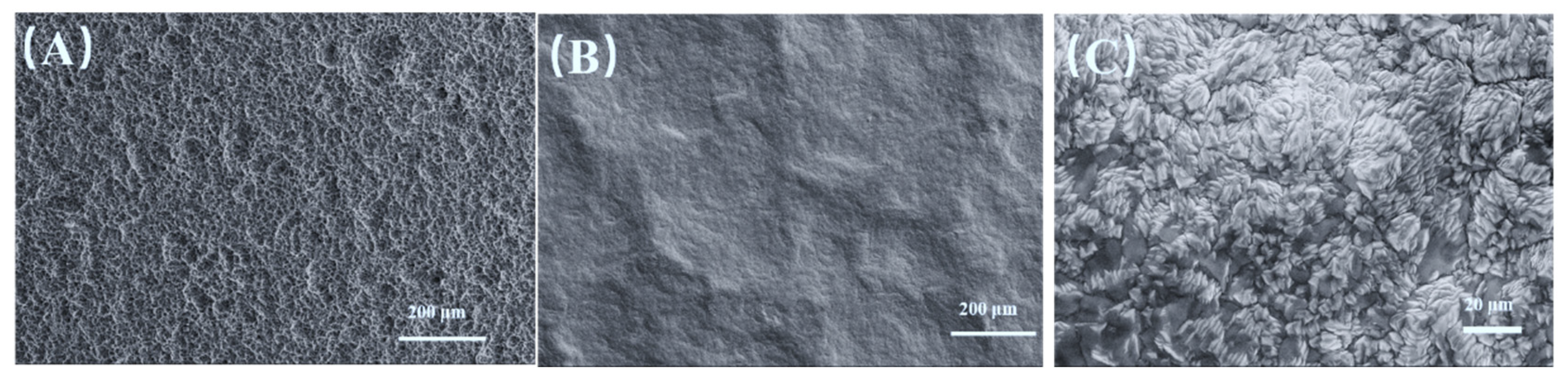
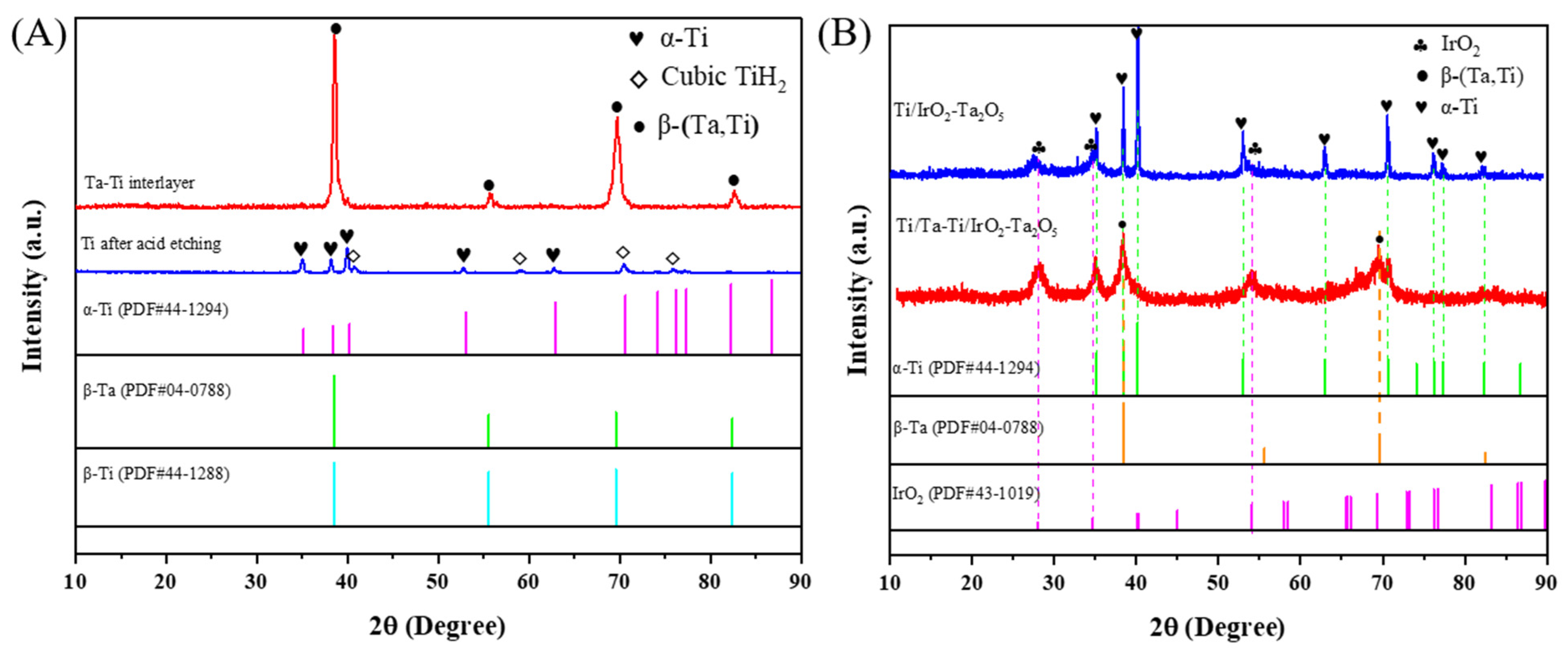
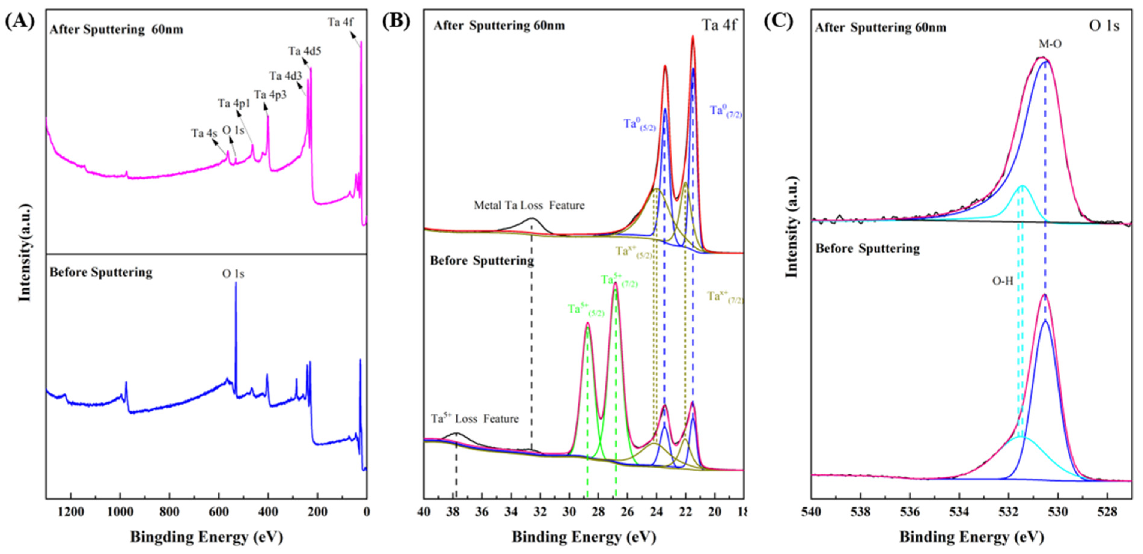
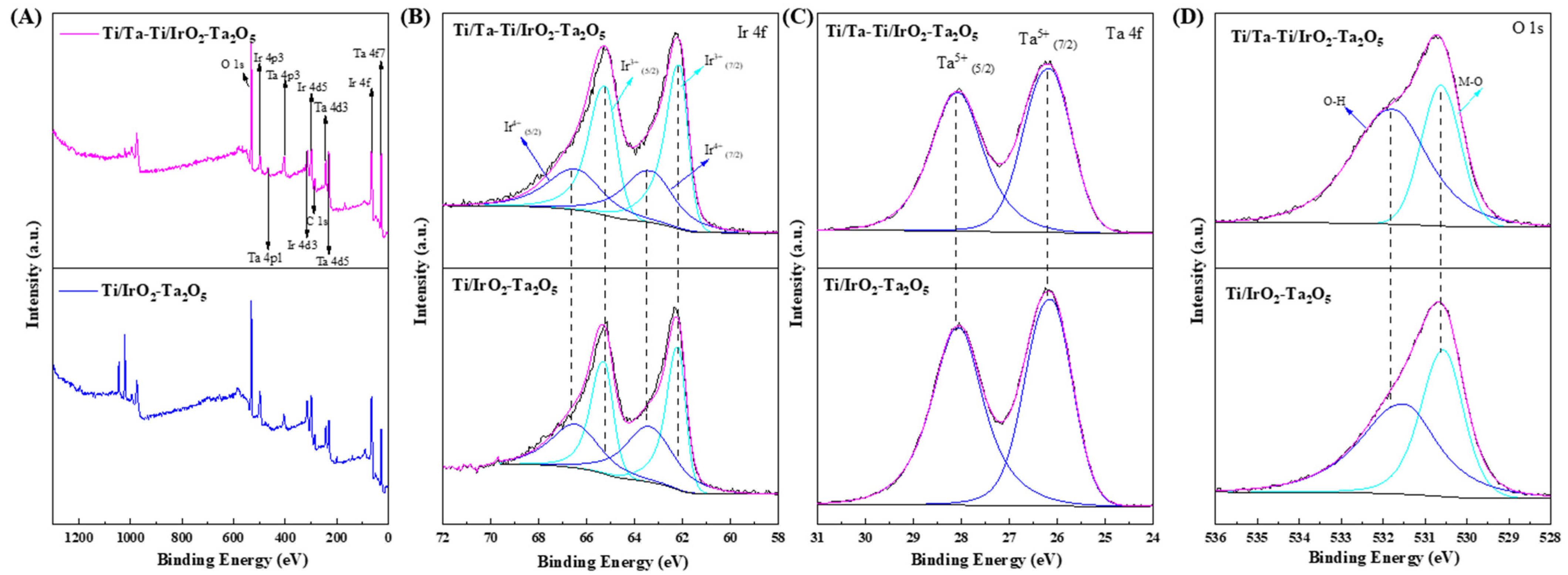
3.1. Microstructure

The surface morphologies of different samples, including the Ti substrate and the Ta-Ti alloy interlayer, are shown in Figure 1. The surface of an acid-etched Ti substrate (Figure 1A) presents a lot of small corrosion pits [39], which benefits the retention of precursor solution on the substrate surface [40], as well as the bonding of coating with the substrate. After the DGPSAT treatment, a coating (Ta-Ti interlayer) was deposited on the etched titanium substrate, as shown in Figure 1B. The etched titanium substrate presents a rough surface morphology, while the deposited coating shows a relatively flat and uniform morphology. The magnified SEM picture (Figure 1C) displays that the interlayer is composed of grains with agglomerated cellular particles in sizes of 0.2~1.0 μm inside. This change in surface morphology with the interlayer deposited would affect the microstructures of the top IrO2-Ta2O5 coatings.
EDS analysis demonstrated that the surface composition of the interlayer consisted mainly of tantalum (Ta), oxygen (O), and titanium (Ti) (Table 2). The small amount of O element should have derived from the slight oxidation of the surface. It can be found that a large amount of Ta, accounting for 92.83 atom %, and a little amount of Ti were observed on the surface of the interlayer. Ta and Ti elements should come from the Ta-Ti alloy interlayer, which has a thickness much larger than that detected using EDS.
The cross-sectional morphology of the Ta-Ti alloy interlayer is shown in Figure 2A, which displays the microstructure of the interlayer changing with depth and can be divided into two stratums. The first stratum is on the top with a thickness of about 4 μm. The second stratum is light gray with a thickness of about 4–8 μm. The gray region below the interlayer is the Ti substrate. The prepared interlayer has a thickness of about 8–12 μm. EDS analysis with line scanning, as shown in Figure 2B, indicated that the Ta content decreased while the Ti content continuously increased with the depth, demonstrating that the interlayer is the Ta-Ti binary alloy with the composition changing along the depth. The first stratum has a content of Ta greater than 41% and almost 100% at the outermost superficial layer. The tantalum content in the second stratum is less than 41% and decreases with depth, indicating that Ti is rich in this stratum. Therefore, the Ta-Ti alloy interlayer prepared via DGPSAT has a gradient composition. Some micro-voids can be found at the interface between the original surface of the substrate and the interlayer. The surface of the etched Ti substrate is rough, which can lead to an inhomogeneous higher vacancy concentration gradient with the substrate bombarded by ions. This mechanism resulted in an uneven distribution of tantalum atom deposition from thermal movement, producing micro-voids of different sizes. Considering that the interlayer undergoes metallurgical bonding with the substrate via surface alloying, and the anode bears little load at working, some discrete micro-voids in the interlayer should not lead to the detachment of the coating. Although these micro defects can be tolerated in the composite anode, the quality of the deposited interlayer should be further improved later by the optimization of the substrate pretreatment and processing parameters.
Figure 3A,B show the SEM morphologies of Ti/IrO2-Ta2O5 and Ti/Ta-Ti/IrO2-Ta2O5 anodes. The surfaces of Ti/IrO2-Ta2O5 and Ti/Ta-Ti/IrO2-Ta2O5 anodes present a similar appearance with some “dried mud” cracks, which are very typical for metal oxide-coated titanium electrodes prepared using the thermal decomposition method [6,38]. The micro-cracks should be caused by the thermal stress produced during the preparation process due to the different thermal expansion coefficients between the substrate and the coating [31,41]. The surface of the Ti/IrO2-Ta2O5 electrode is more uneven than that of the Ti/Ta-Ti/IrO2-Ta2O5 electrode, which can be attributed to the different roughness of the etched Ti substrate and the Ta-Ti interlayer. There are more micro-cracks on the Ti/IrO2-Ta2O5 electrode surface than that on the Ti/Ta-Ti/IrO2-Ta2O5 electrode because the thick coating located at the deep pits or dimples on the substrate suffers higher thermal stress and is liable to cracking. The cracks can increase the area of contact between surface active sites and electrolytes, increasing electrochemical surface area, but they also accelerate the deactivation of the anode, with the substrate being attacked more easily [15].
Furthermore, in the magnified SEM images (Figure 3C,D), some agglomerates of white nano-scale particles are observed with precipitation on the electrode surfaces. Combined with EDS mapping analysis (Figure 3E,F), these white nano-scale particles were identified mainly as IrO2. It has been found that the agglomerates with nanoparticles determined as being IrO2 crystallites are often present on IrO2-Ta2O5 electrodes [15,42]. From Figure 3E, it is evident that IrO2 aggregation occurs, whereas Figure 3F shows a more uniform distribution of IrO2. These differences in surface morphology and EDS mapping suggest that adding the Ta-Ti interlayer reduces the agglomeration of IrO2 nanoparticles, which can enhance the electrocatalytic activity of an electrode due to a more homogeneous distribution of active sites. The precipitation of agglomerates should be related to the roughness of the substrate and the distribution of the thickness of the IrO2-Ta2O5 coating. The locally thin coating at the ridges on the etched Ti substrate facilitates the precipitation and aggregation of nano-IrO2 crystallites during thermal decomposition processes [31,38], while the introduction of the interlayer can lower the surface roughness, thus reducing the aggregation of nano-IrO2 particles.
The results of EDS analysis on the oxide anodes are also listed in Table 2, which shows that Ir, Ta, Ti, O, and Cl elements are detected on the surfaces of Ti/Ta-Ti/IrO2-Ta2O5 and Ti/IrO2-Ta2O5 electrodes. A little chlorine existing in the oxide coating of the electrodes comes from the residual chloride precursor, which may not completely transform to oxides during sintering. The atomic ratio of Ir and Ta for Ti/IrO2-Ta2O5 electrode is about 69:31, close to the nominal composition of the IrO2-Ta2O5 coating (Table 2). The more Ti content detected for Ti/IrO2-Ta2O5 electrode implies that the oxide coating is thin and that X-rays can penetrate the coating or go through the micro-cracks to the Ti substrate. The Ti/Ta-Ti/IrO2-Ta2O5 electrode has a lower Ti content and a higher Ta content than the Ti/IrO2-Ta2O5 electrode relating to the thin oxide coating and the fact that the composition analyzed via EDS is a mixture of the oxide coating and the Ta-Ti interlayer.
The XRD patterns of the different samples are shown in Figure 4. The XRD pattern of acid-etched Ti displays characteristic peaks attributed to the cubic TiH2 phase, as well as the α-Ti phase. These results are in agreement with previous investigations [39]. The detection range in depth when using the XRD technique is generally limited to 10–30 μm, and the EDS analysis of the cross-sectional sample for the Ta-Ti interlayer revealed the coexistence of binary Ti and Ta elements at this depth. The diffraction peaks observed at 38.5°, 55.5°, 69.6°, and 82.5° for the Ta-Ti interlayer correspond to the β-Ta and β-Ti phases, indicating their simultaneous presence in the sample. It should be noted that the DGPSAT process was carried out at a temperature of approximately 900℃, which is adequate to form β-Ta and β-Ti [43,44,45]. Furthermore, based on the Ti-Ta binary phase diagram [46] and combined with the EDS analysis results, it can be found that the first stratum of the alloy interlayer is a solid solution of β-(Ta,Ti), having the same phase structure of β-Ta. For the second stratum, the Ti content is dominant, and the phase composition changes to β-(Ti,Ta). A similar phase structure was reported in the literature that the Ti-Ta alloys with a content of 20–50 atom % Ta produced via powder metallurgy after sintering all have a structure of β phase because Ti and Ta can form a continuous solid solution [47]. It was also found that the stable β-Ta can be formed in the Ta-Ti alloy when the Ta content reaches a certain value [36]. Whether it is β-Ti or β-Ta, their corrosion resistance is superior to that of α-Ti [29,48], indicating that the Ta-Ti interlayer can enhance the corrosion resistance of the substrate.
The peaks of the Ti/IrO2-Ta2O5 and Ti/Ta-Ti/IrO2-Ta2O5 electrodes (Figure 4B) at 28.0°, 34.7°, and 53.5° can be attributed to the IrO2 rutile phase. There exist diffraction peaks of α-Ti substrate in the XRD pattern of the Ti/IrO2-Ta2O5 electrode, while β-(Ta,Ti) peaks appear for the composite electrode with the interlayer. No Ta2O5 peak was detected in both oxide electrodes, suggesting the phase is amorphous because the crystallization of Ta2O5 cannot occur at the low sintering temperature [39]. According to Scherrer’s formula [39,49], the average grain size of the active component of IrO2 can be calculated from the diffraction peaks of IrO2 for the oxide electrodes, which is reduced from about 12 nm to about 9 nm after adding the interlayer, indicating that the IrO2 nano-crystallites in the oxide coating are refined when the interlayer is applied. The reduction in grain size can produce a larger electrochemical active area, which is conducive to improving electrocatalytic activity [31].
X-ray photoelectron spectroscopy (XPS) can be used to analyze the chemical state of the sample surface. The XPS full spectra of the top-surface and the sub-surface at 60 nm depth after ion sputtering of the Ta-Ti interlayer are shown in Figure 5A. The detection depth of XPS is generally less than 10 nm. As the full spectrum displays, the superficial surface of the interlayer was found to contain tantalum (Ta) and oxygen (O) elements, with no evidence of the presence of titanium (Ti). This observation suggests that the surface composition of the interlayer comprises metallic tantalum and tantalum oxide.
Figure 5B,C show the XPS spectra of high-resolution electron binding energy for Ta 4f and O 1s. The Ta 4f peaks at around 21.5/23.5 eV and 26.8/28.75 eV are assigned to metallic Ta and Ta2O5 [50], respectively. While the peaks at 22/24.05 eV are attributed to low-valent tantalum oxide (Tax+, 0 < x < 5) [50]. The absence of tantalum pentoxide on the sub-surface suggests that the oxidation of tantalum is limited to its top-surface during the DGPSAT process. A similar phenomenon of oxidation at the superficial surface was also observed in other high-vacuum preparation techniques relating to tantalum coatings, such as magnetron sputtering [51,52] and chemical vapor deposition [53], which can be explained by the high sensitivity of tantalum to oxygen at high temperatures [29]. The disappearance of the diffraction peak of tantalum pentoxide and the reduction of 0.1 eV in the binding energy of the lower-valence oxide were observed in the sub-surface, which can be attributed to the reduction of the oxide due to ion sputtering. The O 1s peaks at 530.55 eV are attributed to the lattice oxygen [54], and the peaks at 531.45 eV are assigned to hydroxides [55]. The stability of lattice oxygen is unaffected by ion bombardment, whereas the binding energy of hydroxides shifted 0.2 eV towards a positive direction, suggesting that they are predominantly located on the top-surface [42]. The element contents detected using XPS are listed in Table 3. It can be found that the oxygen content decreases significantly in the interlayer after ion sputtering to remove the superficial layer. The results indicate that the surface layer of the Ta-Ti interlayer is composed of metallic tantalum and conductive tantalum suboxide, and only the top-surface is oxidized to pentoxide.
Figure 6 shows the XPS spectra of Ti/IrO2-Ta2O5 and Ti/Ta-Ti/IrO2-Ta2O5 electrodes. The full spectra of the oxide electrodes (Figure 6A) demonstrate that the oxide coatings are composed of Ir, Ta, and O. In the Ir 4f spectra, the binding energies located at 62.1/65.35 eV and 63.45/66.5 eV correspond to Ir3+ and Ir4+ species, respectively [56,57]. The coexistence of Ir3+ and Ir4+ species is often found in IrO2-Ta2O5 coating prepared via the thermal decomposition method [51,52,53], and the transformation of Ir3+/Ir4+ redox can facilitate the oxygen evolution reaction (OER), resulting in a reduction in the OER potential [58]. The binding energies at 26.1 and 28.15 eV in the Ta 4f spectrum correspond to Ta2O5. The O 1s spectrum presents two peaks at 530.65 eV and 531.6 eV belonging to the lattice oxygen and hydroxides, respectively. Therefore, the IrO2-Ta2O5 coatings prepared on either the Ta-Ti interlayer or the Ti substrate via the thermal decomposition method have almost no difference in electronic structure. For the Ti/IrO2-Ta2O5 electrode, the Ir/Ta ratio is observed to be a little large as compared to that for the Ti/Ta-Ti/IrO2-Ta2O5 electrode (see Table 3). This discrepancy can potentially be explained by the diffusion of tantalum from the interlayer [59]. Moreover, the Ir/Ta ratio for both electrodes is smaller than the nominal composition as well as the results when using EDS analysis (see Table 2), which can be attributed to the surface segregation phenomenon, leading to a lower concentration of Ir [60].

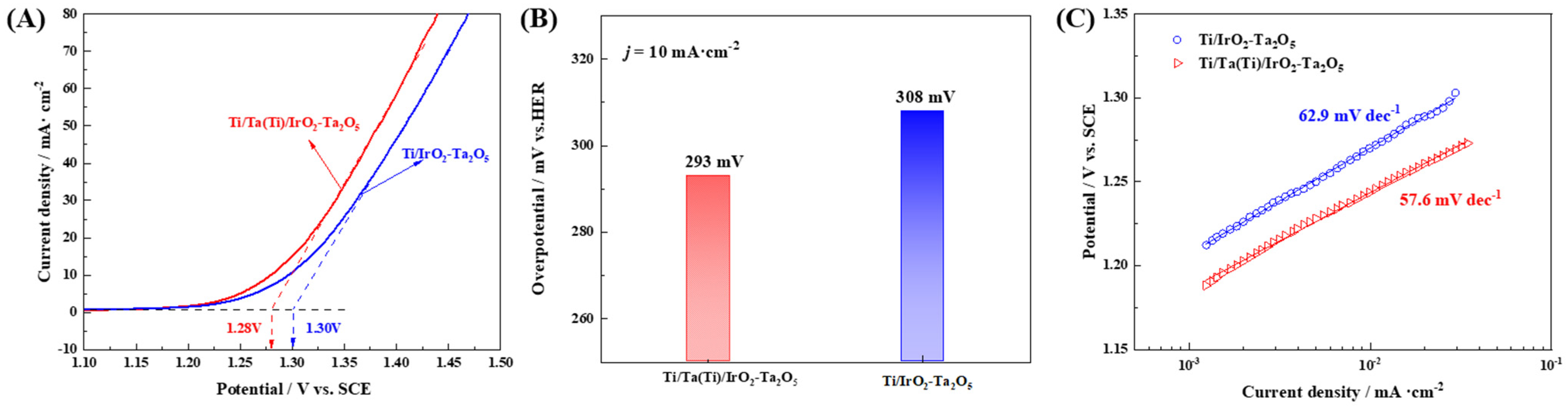
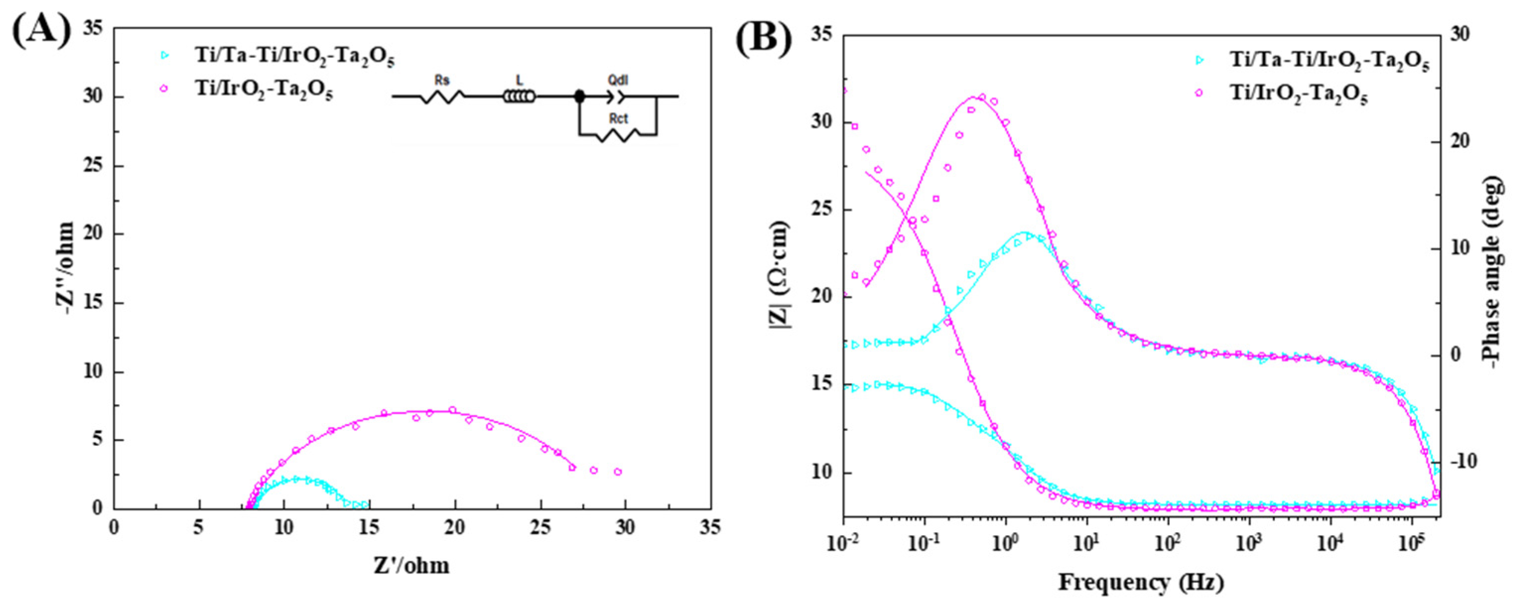
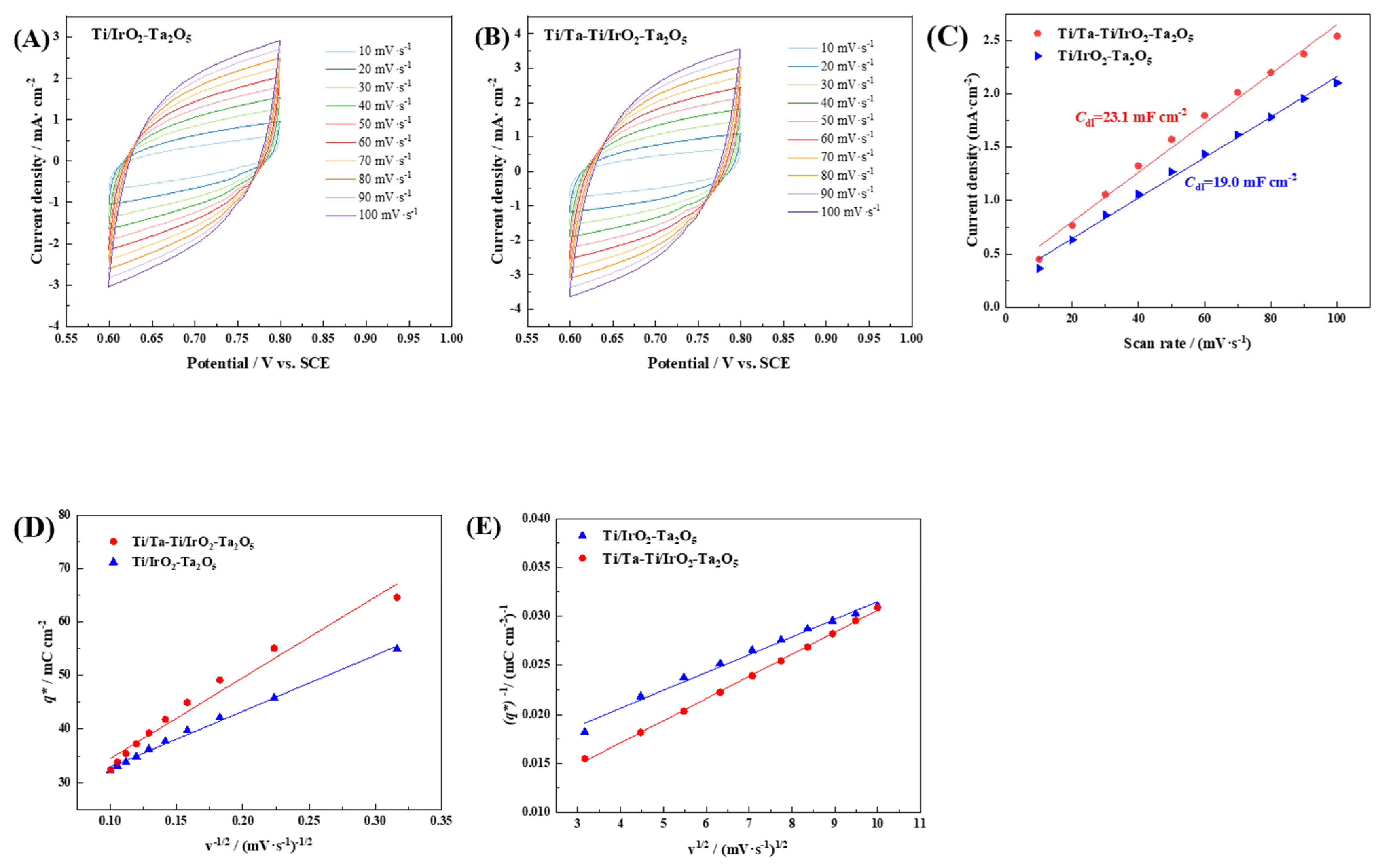
3.2. Electrocatalytic Activity
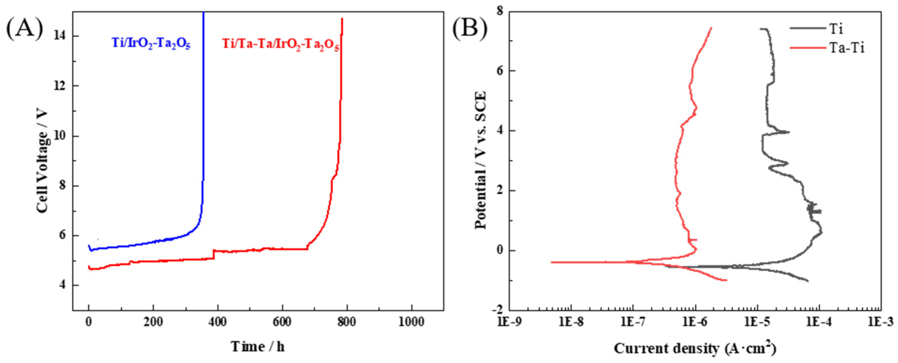
The electrochemical performance of the Ti/IrO2-Ta2O5 and Ti/Ta-Ti/IrO2-Ta2O5 electrodes was characterized using LSV, EIS and CV measurements. The LSV curves corrected with iR drop are shown in Figure 7A. It can be found that the Ti/Ta-Ti/IrO2-Ta2O5 electrode presents a lower OER onset potential and a larger current density for oxygen evolution at the constant working potential than the Ti/IrO2-Ta2O5 electrode. The Ti/Ta-Ti/IrO2-Ta2O5 electrode exhibits excellent OER activity, with an overpotential of 293 mV to reach the current density of 10 mA·cm−2 (Figure 7B). In contrast, the Ti/IrO2-Ta2O5 electrode requires a higher overpotential of 308 mV at the same current density. In addition, the Ti/Ta-Ti/IrO2-Ta2O5 electrode has a lower Tafel slope than the Ti/IrO2-Ta2O5 electrode for OER (Figure 7C). The LSV results indicate that the Ti/Ta-Ti/IrO2-Ta2O5 electrode exhibits a higher OER electrocatalytic activity than the Ti/IrO2-Ta2O5 electrode.
The EIS spectra recorded at 1.4 V (vs. SCE) in 0.5 mol·L−1 H2SO4 solution are shown in Figure 8A. For both electrodes, the Nyquist diagrams displayed a depressed semi-circle, indicating the presence of a relaxation process with a single time constant. However, the absence of a capacitive arc at higher frequencies is noteworthy as it suggests that neither electrode exhibited a reduction in the conductivity of its oxide coating or an insulating oxide layer formed on the substrate beneath the IrO2-Ta2O5 coating [6,15]. No semi-circle has been found in the high-frequency region, which proves that neither Ti substrate nor Ta-Ti interlayer has been further oxidized during the preparation of the top oxide coating via thermal decomposition. The small flat tails appearing at the low frequencies should be related to the bubble effect due to strong gas evolution [31]. The semi-circle diameter of the Ti/Ta-Ti/IrO2-Ta2O5 electrode is smaller than that of the Ti/IrO2-Ta2O5 electrode, indicating that the introduction of the Ta-Ti interlayer via DGPSAT can promote the electrocatalytic activity of the IrO2-Ta2O5 electrode. The equivalent circuit model in Figure 8A was used to fit the EIS spectra, and the corresponding parameters are given in Table 4. In the equivalent circuit, Rs, L, Rct, and Qdl are the solution resistance, the inductance, the charge transfer resistance, and the constant phase element, respectively. Qdl is used to replace the double-layer capacitance to obtain a better simulation due to the dispersive effect from the rough surface of the electrode [31]. The inductance present at high frequency should be related to the interference in the electrical circuit. The Rct of the Ti/Ta-Ti/IrO2-Ta2O5 electrode is smaller than that of the Ti/IrO2-Ta2O5 electrode, indicating that the Ta-Ti interlayer can enhance the electrocatalytic activity of oxygen evolution reaction. In addition, the Ti/Ta-Ti/IrO2-Ta2O5 electrode has a larger Qdl than the Ti/IrO2-Ta2O5 electrode, suggesting that the electrode with the Ta-Ti interlayer has a larger electrochemical active surface area, which agrees with the LSV results.
The voltametric charge and electrochemical double-layer capacitance of the electrodes can be measured via cyclic voltammetry. The CV curves taken at different scan rates in the potential range of 0.6 V~0.8 V (vs. SCE) are given in Figure 9A,B. The relationship between the current density Δj (ja − jc) at 0.7 V (vs. SCE) and the scanning rate is shown in Figure 9C, from which the double-layer capacitance can be derived as the slope of the fitting line. The Cdl value of the Ti/Ta-Ti/IrO2-Ta2O5 electrode (23.1 ± 0.9 mF·cm−2) is greater than that of the Ti/IrO2-Ta2O5 electrode (19.0 ± 0.5 mF·cm−2), as shown in Table 5. Given that there exists a correlation between the double-layer capacitance and the surface area of the electrode that participates in electrochemical reactions, which is commonly referred to as the electrochemically active surface area (EASA), it can be considered that an increase in Cdl will result in a corresponding increase in EASA [61]. The Cdl result demonstrates that the Ti/Ta-Ti/IrO2-Ta2O5 electrode has a larger EASA, thereby a higher electrocatalytic activity than the Ti/IrO2-Ta2O5 electrode.
The voltammetric charge, q, obtained from the cyclic voltammetry curve is proportional to the number of electroactive sites present on the electrode surface [56]. At high scan rates, electrochemical reactions between active sites and electrolyte solutions occur more easily in the “outer” surface region. At low scan rates, the exchange reaction occurs predominantly in the “total” region (both the “outer” and “inner” active surface regions) [62]. The functional relationship between the voltammetric charge and the scanning rate can be described using the following equations [42]. The charge of the “outer” active surface in contact with the electrolyte, q o u t , can be obtained from Equation (1). The “total” voltammetric charge, q t o t * , can be obtained from Equation (2). The charge of the “inner” active surface hidden in pores and cracks, q i n * , can be calculated from Equation (3).
q = q o u t + k 1 v 0.5
q 1 = q t o t 1 + k 2 v 0.5
q t o t = q o u t + q i n  
where k1 and k2 are constants, v is the potential scanning rate. Figure 9D,E show the plots of the relationship between q and v for Ti/IrO2-Ta2O5 and Ti/Ta-Ti/IrO2-Ta2O5 electrodes, and the derived voltammetric charges are also listed in Table 5. The total voltammetric charge observed for the Ti/Ta-Ti/IrO2-Ta2O5 electrode is significantly greater than that of the Ti/IrO2-Ta2O5 electrode, suggesting that the former possesses a larger electrochemically active surface area. The charge of the inner surface for both electrodes is much larger than that of the outer surface. It can also be found that the qin for the Ti/Ta-Ti/IrO2-Ta2O5 electrode is much larger than that for Ti/IrO2-Ta2O5 electrode. These results demonstrate that the enhanced electrocatalytic activity of the Ti/Ta-Ti/IrO2-Ta2O5 electrode mainly originates from the large inside of EASA. Although the Ti/Ta-Ti/IrO2-Ta2O5 electrode surface has fewer micro-cracks, the dispersed nano IrO2 particles and the refinement of IrO2 crystallites with the interlayer added increase the number of electrocatalytic active sites, thereby enhancing the voltammetric charges [63].

3.3. Stability

Accelerated life testing (ALT) is a commonly used method to assess the stability of Ti/IrO2-Ta2O5 anodes [8]. The ALT was carried out at 3 A·cm−2 in 1 mol·L−1 H2SO4 solution, and the time taken for the cell voltage to reach 10 V was considered the life of the electrode. Figure 10A shows the evolution of cell voltage with electrolysis time for Ti/Ta-Ti/IrO2-Ta2O5 and Ti/IrO2-Ta2O5 electrodes. Both electrodes exhibit similar behavior, with a slight decrease in cell voltage in the early stage due to electrolyte penetration through the pores, cracks, and grain boundaries of the oxide coating. As the ALT continues, the cell voltage increases slowly until it rises rapidly in the last stage, indicating the failure of the electrode. It should be noted that there is a small step-rise of voltage during the electrolysis for the electrode with the interlayer, which is related to the replacement of the electrolyte. The ALT life of the Ti/Ta-Ti/IrO2-Ta2O5 electrode was found to be 779 ± 18 h, more than twice that of the Ti/IrO2-Ta2O5 electrode (348 ± 21 h). Additionally, the initial cell voltage of the Ti/Ta-Ti/IrO2-Ta2O5 electrode is lower, indicating better electrochemical activity than the Ti/IrO2-Ta2O5 electrode. These results demonstrate that the addition of a Ta-Ti interlayer via DGPSAT significantly improves the service life of the electrode, which is attributed to the high corrosion resistance of the Ta-Ti interlayer, providing effective protection for the Ti substrate [24,28,29].
To demonstrate the corrosion resistance of the Ta-Ti interlayer and the Ti substrate, potentiodynamic polarization curves for the Ta-Ti interlayer and Ti substrate in 1 mol L−1 H2SO4 solution were measured, as shown in Figure 10B. The results indicate that both the Ti substrate and the Ta-Ti alloy interlayer exhibit similar passivation behavior in sulfuric acid solution. However, the passivation current density of the Ta-Ti interlayer is approximately an order of magnitude lower than that of the Ti substrate. Additionally, the corrosion potential of the Ta-Ti alloy layer is 149 mV higher than that of titanium, and the corrosion current density of the Ta-Ti interlayer is much smaller than that of the Ti substrate. These results suggest that the corrosion resistance of the Ti substrate is greatly enhanced after Ta-Ti alloying via DGPSAT. The Ta-Ti alloy layer can protect the Ti substrate effectively, thereby enhancing electrode stability and extending electrode lifespan.
Moreover, the surface of the Ti/Ta-Ti/IrO2-Ta2O5 electrode exhibits reduced micro-cracks and less agglomerates of IrO2 nanoparticles, which can slow the infiltration of electrolyte solution through the cracks of IrO2-Ta2O5 coating to the substrate and avoid the fast dissolution and detachment of IrO2 agglomerates precipitated on the surface. The large electrochemically active surface area of the Ti/Ta-Ti/IrO2-Ta2O5 electrode can also lower the real working current density during the electrolysis. All of these effects can improve the stability of the oxide electrode.
It should be emphasized that the specific micro-mechanism for the Ta-Ti interlayer to enhance the stability of the oxide anode still needs to be studied further, though it is generally ascribed to the protection of the interlayer for the Ti substrate [24,28]. The addition of a Ta-Ti interlayer will increase the cost of the oxide electrode; however, it should be cost-effective considering the high performance of the electrode with the interlayer. Furthermore, although it has been ascertained that deposition of a Ta-Ti interlayer via DGPSAT can significantly enhance the electrochemical performance of the IrO2-Ta2O5 electrode, optimization of the preparation processes is still required, and the fabrication of a large-size electrode using this method is also a challenge.

4. Conclusions

A Ta-Ti alloy interlayer has been deposited on a Ti substrate via the double-glow plasma surface alloying technology to prepare a Ti/Ta-Ti/IrO2-Ta2O5 composite electrode. The microstructures of the interlayer and the oxide electrodes have been examined using SEM, EDS, XRD and XPS, and the electrochemical properties of the Ti/IrO2-Ta2O5 and Ti/Ta-Ti/IrO2-Ta2O5 electrodes have been tested via LSV, EIS, CV and ALT, respectively. The following conclusions can be drawn from this investigation:
(1) The Ta-Ti interlayer prepared using double-glow plasma surface alloying technology presents a relatively flat and uniform morphology with agglomerated cellular particles on the surface. The interlayer has a varying composition of continuously increasing Ti content and decreasing Ta content in depth. XRD analysis revealed that the Ta-Ti alloy interlayer is composed of solid solutions with β phases. XPS analysis showed that the top-surface layer of the Ta-Ti interlayer is composed of metallic Ta and a small amount of Ta oxides, while the sub-surface consists of Ta and conductive Ta suboxides.
(2) The Ti/Ta-Ti/IrO2-Ta2O5 electrode has fewer micro-cracks and less aggregation of nano-IrO2 particles than the Ti/IrO2-Ta2O5 electrode. XRD analysis showed that the Ta-Ti interlayer can reduce the grain size of rutile IrO2. No significant differences in surface composition were detected for the two electrodes. The Ir/Ta ratio in the superficial layer for both electrodes is smaller than that in the oxide coating due to surface segregation.
(3) The Ti/Ta-Ti/IrO2-Ta2O5 electrode has an obviously higher electrocatalytic activity for oxygen evolution than the Ti/IrO2-Ta2O5 electrode, which is attributed to the introduction of the interlayer that reduces the aggregation of IrO2 nanoparticles and refines the IrO2 crystallites, thereby increasing the electrochemically active surface area. The accelerated life test demonstrates that the Ti/Ta-Ti/IrO2-Ta2O5 electrode has a much higher stability than the Ti/IrO2-Ta2O5 electrode, which is attributed to the high corrosion resistance of the Ta-Ti alloy interlayer and the effective protection of the Ti substrate. Furthermore, the reduced surface micro-cracks, fewer agglomerates of IrO2 particles, and the enlargement of the electrochemically active surface area via the introduction of the interlayer also improve the stability of the oxide electrode.

Author Contributions

Conceptualization, investigation and methodology, Y.L. and M.G.; writing—original draft preparation, M.G.; writing—review and editing, L.X. (Likun Xu); supervision, L.X. (Likun Xu), L.X. (Lili Xue) and L.L.; funding acquisition, L.X. (Likun Xu) and Y.X.; data curation, T.D. and J.X.; validation, R.Z. All authors have read and agreed to the published version of the manuscript.

Funding

This work was supported by Luoyang Ship Material Research Institute (KW230405).

Data Availability Statement

The data that support the results of this study are available from the corresponding author upon reasonable request.

Acknowledgments

The authors are grateful for the support provided by Luoyang Ship Material Research Institute.

Conflicts of Interest

The authors declare no conflicts of interest.

References

  1. Zhou, Q.; Liu, D.; Yuan, G.; Tang, Y.; Cui, K.; Jiang, S.; Xia, Y.; Xiong, W. Efficient degradation of phenolic wastewaters by a novel Ti/PbO2-Cr-PEDOT electrode with enhanced electrocatalytic activity and chemical stability. Sep. Purif. Technol. 2022, 281, 119735. [Google Scholar] [CrossRef]
  2. Zhao, R.; Wang, Y.M.; Li, J.; Meng, W.; Yang, C.; Sun, C.; Lan, X. Metal modified (Ni, Ce, Ta) Ti/SnO2-Sb2O5-RuO2 electrodes for enhanced electrochemical degradation of Orange G. J. Appl. Electrochem. 2022, 52, 573–581. [Google Scholar] [CrossRef]
  3. Yu, S.; Xie, Z.; Li, K.; Ding, L.; Wang, W.; Yang, G.; Zhang, F.-Y. Morphology engineering of iridium electrodes via modifying titanium substrates with controllable pillar structures for highly efficient oxygen evolution reaction. Electrochim. Acta 2022, 405, 139797. [Google Scholar] [CrossRef]
  4. Wang, W.; Wang, K.; Hao, W.; Zhang, T.; Liu, Y.; Yu, L.; Li, W. Preparation of Ti-based Yb-doped SnO2-RuO2 electrode and electrochemical oxidation treatment of coking wastewater. J. Rare Earth 2022, 40, 763–771. [Google Scholar] [CrossRef]
  5. Chagnes, A.; Pospiech, B. A brief review on hydrometallurgical technologies for recycling spent lithium-ion batteries. J. Chem. Technol. Biot. 2013, 88, 1191–1199. [Google Scholar] [CrossRef]
  6. Xu, L.K.; Scantlebury, J.D. Microstructure and electrochemical properties of IrO2-Ta2O5-coated titanium anodes. J. Electrochem. Soc. 2003, 150, B254. [Google Scholar] [CrossRef]
  7. Li, B.S.; Lin, A.; Gan, F.X. Preparation and electrocatalytic properties of Ti/IrO2-Ta2O5 anodes for oxygen evolution. T. Nonferr. Metal Soc. 2006, 16, 1193–1199. [Google Scholar] [CrossRef]
  8. Herrada, R.A.; Rodil, S.E.; Sepúlveda-Guzmán, S.; Manríquez, J.; Exner, K.S.; Bustos, E. Characterization of Ti electrodes electrophoretically coated with IrO2-Ta2O5 films with different Ir:Ta molar ratios. J. Alloy Compd. 2021, 862, 158015. [Google Scholar] [CrossRef]
  9. Yan, Z.; Li, G.; Wang, J.; Zhang, Z.; Feng, Z.; Tang, M.; Zhang, R. Electro-catalytic study of IrO2-Ta2O5 coated anodes with pretreated titanium substrates. J. Alloy Compd. 2016, 680, 60–66. [Google Scholar] [CrossRef]
  10. Xu, W.; Haarberg, G.M.; Seland, F.; Sunde, S.; Ratvik, A.P.; Holmin, S.; Gustavsson, J.; Afvander, Å.; Zimmerman, E.; Åkre, T. The durability of the thermally decomposed IrO2-Ta2O5 coated titanium anode in a sulfate solution. Corros. Sci. 2019, 150, 76–90. [Google Scholar] [CrossRef]
  11. Han, Z.; Zhu, P.; Xu, L.; Kannan, C.S.; Guo, S.; Liu, J.; Koppala, S.; Ju, S. Electrochemical properties of the IrO2-Ta2O5 coated anodes with Al/Ti and Cu/Ti layered composites substrates. J. Alloy Compd. 2018, 769, 210–217. [Google Scholar] [CrossRef]
  12. Huang, C.A.; Yang, S.W.; Chen, C.Z.; Hsu, F.-Y. Electrochemical behavior of IrO2-Ta2O5/Ti anodes prepared with different surface pretreatments of Ti substrate. Surf. Coat. Technol. 2017, 320, 270–278. [Google Scholar] [CrossRef]
  13. Comninellis, C.; Vercesi, G.P. Characterization of DSA®-type oxygen evolving electrodes: Choice of a Coating. J. Appl. Electrochem. 1991, 21, 335–345. [Google Scholar] [CrossRef]
  14. Liu, Y.; Xu, L.; Xuan, J.; Xin, Y.; Li, Y.; Duan, T.; Liu, F. A comparative study on Ti/IrO2–Ta2O5 anodes prepared by microwave plasma-assisted sintering and conventional thermal decomposition methods. J. Mater. Res. Technol. 2023, 23, 1447–1457. [Google Scholar] [CrossRef]
  15. Xu, L.K.; Scantlebury, J.D. A study on the deactivation of an IrO2–Ta2O5 coated titanium anode. Corros. Sci. 2003, 45, 2729–2740. [Google Scholar] [CrossRef]
  16. Hu, J.M.; Meng, H.M.; Zhang, J.Q.; Cao, C.N. Degradation mechanism of long service life Ti/IrO2-Ta2O5 oxide anodes in sulphuric acid. Corros. Sci. 2002, 44, 1655–1668. [Google Scholar] [CrossRef]
  17. Chen, A.; Nigro, S. Influence of a nanoscale gold thin layer on Ti/SnO2-Sb2O5 electrodes. J. Phys. Chem. B 2003, 107, 13341–13348. [Google Scholar] [CrossRef]
  18. Tang, C.; Liu, Z.; Cui, D.; Yu, L.; Xue, J.; Yin, X. Enhancing the stability and electrocatalytic activity of Ti-based PbO2 anodes by introduction of an arc-sprayed TiN interlayer. Electrochim. Acta 2021, 399, 139398. [Google Scholar] [CrossRef]
  19. Li, X.; Yan, J.; Zhu, K.G. Effects of IrO2 interlayer on the electrochemical performance of Ti/Sb-SnO2 electrodes. J. Electroanal. Chem. 2020, 878, 114471. [Google Scholar] [CrossRef]
  20. Li, X.L.; Xu, H.; Yan, W. Electrochemical oxidation of aniline by a novel Ti/TiOxHy/Sb-SnO2 electrode. Chin. J. Catal. 2016, 37, 1860–1870. [Google Scholar] [CrossRef]
  21. Xu, H.B.; Lu, Y.H.; Li, C.H.; Hu, J.Z. A novel IrO2 electrode with iridium-titanium oxide interlayers from a mixture of TiN nanoparticle and H2IrCl6 solution. J. Appl. Electrochem. 2010, 40, 719–727. [Google Scholar] [CrossRef]
  22. Salgado, L.; Pozos, C.B.; Zayas, T.; Galicia, L. Preparation and characterization of Ti/SnO2-Sb electrodes without or with a platinum interlayer using the polymeric precursor method and thermal decomposition. Int. J. Electrochem. Sci. 2019, 14, 7281–7292. [Google Scholar] [CrossRef]
  23. Tang, C.B.; Zheng, C.; Yu, L.H.; Xue, J.Q. Effect of electroplating nickel interlayer on performance of Ti-based lead dioxide electrodes. Rare Metal. Mat. Eng. 2019, 48, 143–151. [Google Scholar]
  24. Piercy, B.; Allen, C.; Gullá, A.F. Ta and Ti anti-passivation interlayers for oxygen-evolving anodes produced by cold gas spray. J. Therm. Spray. Technol. 2015, 24, 702–710. [Google Scholar] [CrossRef]
  25. Jin, H.C.; Zhang, X.J.; Yu, Y.; Chen, X.M. High-performance Ti/IrO2-RhOx-TiO2/alpha-PbO2/beta-PbO2 electrodes for scale inhibitors degradation. Chem. Eng. J. 2022, 435, 135167. [Google Scholar] [CrossRef]
  26. Zanta, C.L.P.S.; Michaud, P.A.; Comninellis, C.; De Andrade, A.R.; Boodts, J.F.C. Electrochemical oxidation of p-chlorophenol on SnO2-Sb2O5 based anodes for wastewater treatment. J. Appl. Electrochem. 2003, 33, 1211–1215. [Google Scholar] [CrossRef]
  27. Mameda, N.; Park, H.; Shah, S.S.A.; Lee, K.; Li, C.W.; Naddeo, V.; Choo, K.H. Highly robust and efficient Ti-based Sb-SnO2 anode with a mixed carbon and nitrogen interlayer for electrochemical 1,4-dioxane removal from water. Chem. Eng. J. 2020, 393, 124794. [Google Scholar] [CrossRef]
  28. Cardarelli, F.; Taxil, P.; Savall, A.; Comninellis, C.; Manoli, G.; Leclerc, O. Preparation of oxygen evolving electrodes with long service life under extreme conditions. J. Appl. Electrochem. 1998, 28, 245–250. [Google Scholar] [CrossRef]
  29. Vercesi, G.P.; Rolewicz, J.; Comninellis, C.; Hinder, J. Characterization of dsa-type oxygen evolving electrodes. Choice Base Metal. Thermochim. Acta 1991, 176, 31–47. [Google Scholar] [CrossRef]
  30. Meng, F.; Li, Z.; Liu, X. Synthesis of tantalum thin films on titanium by plasma immersion ion implantation and deposition. Surf. Coat. Technol. 2013, 229, 205–209. [Google Scholar] [CrossRef]
  31. Liu, Y.; Xu, L.; Xin, Y.; Liu, F.; Xuan, J.; Guo, M.; Duan, T. IrO2-Ta2O5 anode for oxygen evolution with TaOx interlayer prepared by thermal decomposition in inert atmosphere. J. Electrochem. Soc. 2022, 169, 6516. [Google Scholar] [CrossRef]
  32. Xu, Z.; Liu, X.; Zhang, P.; Zhang, Y.; Zhang, G.; He, Z. Double glow plasma surface alloying and plasma nitriding. Surf. Coat. Technol. 2007, 201, 4822–4825. [Google Scholar] [CrossRef]
  33. Song, J.; Zhang, P.-Z.; Wei, D.-B.; Wei, X.-F.; Wang, Y. Isothermal oxidation behavior and microstructure of plasma surface Ta coating on γ-TiAl. Mater. Charact. 2014, 98, 54–59. [Google Scholar] [CrossRef]
  34. Wu, H.; Zhang, P.; Wang, L.; Zhao, H.; Xu, Z. The role of process parameters in plasma surface chromising of Ti2AlNb-based alloys. Appl. Surf. Sci. 2009, 256, 1333–1340. [Google Scholar] [CrossRef]
  35. Zhang, C.; Wu, H.; Wang, L.; Yang, X.; Pei, H.; Wei, Y.; Ren, J.; Huang, K.; Hu, L. Role of the double-glow plasma pre-sputtering in the growth mechanisms and metal–insulator transition of VO2 film. Appl. Surf. Sci. 2022, 603, 154043. [Google Scholar] [CrossRef]
  36. Wei, D.B.; Chen, X.H.; Zhang, P.Z.; Ding, F.; Li, F.K.; Yao, Z.J. Plasma surface tantalum alloying on titanium and its corrosion behavior in sulfuric acid and hydrochloric acid. Appl. Surf. Sci. 2018, 441, 448–457. [Google Scholar] [CrossRef]
  37. Xuan, W.; Zhang, P.; Huang, J. Corrosion resistance of tantalum modified layer on pure titanium surface in H2SO4 solution. Mater. Mech. Eng. 2010, 34, 50–53. [Google Scholar]
  38. Xu, L.; Xin, Y.; Wang, J. A comparative study on IrO2–Ta2O5 coated titanium electrodes prepared with different methods. Electrochim. Acta 2009, 54, 1820–1825. [Google Scholar] [CrossRef]
  39. Yan, Z.; Zhao, Y.; Zhang, Z.; Li, G.; Li, H.; Wang, J.; Feng, Z.; Tang, M.; Yuan, X.; Zhang, R.; et al. A study on the performance of IrO2–Ta2O5 coated anodes with surface treated Ti substrates. Electrochim. Acta 2015, 157, 345–350. [Google Scholar] [CrossRef]
  40. Kim, K.-W.; Lee, E.-H.; Kim, J.-S.; Shin, K.-H.; Kim, K.-H. Effect of an etching Ti substrate on a catalytic oxide electrode. J. Electrochem. Soc. 2001, 148, B111–B115. [Google Scholar] [CrossRef]
  41. Zhang, Y.H.; Jiang, W.Q.; Dong, H.; Hu, X.Y.; Fang, B.H.; Gao, G.F.; Zhao, R. Study on the electrochemical removal mechanism of oxytetracycline by a Ti/IrO2-Ta2O5 Plate. Int. J. Environ. Res. Public Health 2021, 18, 1708. [Google Scholar] [CrossRef] [PubMed]
  42. Kodintsev, I.M.; Trasatti, S.; Rubel, M.; Wieckowski, A.; Kaufher, N. X-ray photoelectron spectroscopy and electrochemical surface characterization of iridium(IV) oxide + ruthenium(IV) oxide electrodes. Langmuir 1992, 8, 283–290. [Google Scholar] [CrossRef]
  43. Barksdale, J. Titanium, Its Occurrence, Chemistry, and Technology. Soil. Sci. 1950, 70, 414. [Google Scholar] [CrossRef]
  44. Duan, Y.; Wu, Y.; Peng, M.; Qi, H. The interstitial diffusion behaviors and mechanisms of boron in α-Ti and β-Ti: A first-principles calculation. Comp. Mater. Sci. 2020, 184, 109866. [Google Scholar] [CrossRef]
  45. Murray, J.L. The Ta−Ti (Tantalum-Titanium) system. Bull. Alloy Phase Diagr. 1981, 2, 62–66. [Google Scholar] [CrossRef]
  46. Maykuth, D.J.; Ogden, H.R.; Jaffee, R.I. Titanium-tungsten and titanium-tantalum systems. Trans. Am. Inst. Min. Metall. Eng. 1953, 197, 231–237. [Google Scholar]
  47. Liu, Y.; Li, K.; Wu, H.; Song, M.; Wang, W.; Li, N.; Tang, H. Synthesis of Ti–Ta alloys with dual structure by incomplete diffusion between elemental powders. J. Mech. Behav. Biomed. 2015, 51, 302–312. [Google Scholar] [CrossRef]
  48. Dai, N.; Zhang, L.-C.; Zhang, J.; Zhang, X.; Ni, Q.; Chen, Y.; Wu, M.; Yang, C. Distinction in corrosion resistance of selective laser melted Ti-6Al-4V alloy on different planes. Corros. Sci. 2016, 111, 703–710. [Google Scholar] [CrossRef]
  49. Liu, B.; Wang, C.Y.; Chen, Y.Q.; Ma, B.Z. Electrochemical behavior and corrosion mechanism of Ti/IrO2-RuO2 anodes in sulphuric acid solution. J. Electroanal. Chem. 2019, 837, 175–183. [Google Scholar] [CrossRef]
  50. Simpson, R.; White, R.G.; Watts, J.F.; Baker, M.A. XPS investigation of monatomic and cluster argon ion sputtering of tantalum pentoxide. Appl. Surf. Sci. 2017, 405, 79–87. [Google Scholar] [CrossRef]
  51. Wilks, J.A.; Kelber, J.A. Nitridation of organo-silicate glass: A self-limiting process for PVD Ta1+xN/Ta barrier formation. Appl. Surf. Sci. 2009, 255, 9543–9547. [Google Scholar] [CrossRef]
  52. Wilks, J.A.; Magtoto, N.P.; Kelber, J.A.; Arunachalam, V. Interfacial reactions during sputter deposition of Ta and TaN films on organosilicate glass: XPS and TEM results. Appl. Surf. Sci. 2007, 253, 6176–6184. [Google Scholar] [CrossRef]
  53. Manso, A.P.; Marzo, F.F.; Garicano, X.; Alegre, C.; Lozano, A.; Barreras, F. Corrosion behavior of tantalum coatings on AISI 316L stainless steel substrate for bipolar plates of PEM fuel cells. Int. J. Hydrogen Energy 2020, 45, 20679–20691. [Google Scholar] [CrossRef]
  54. McNamara, K.; Beloshapkin, S.; Hossain, K.M.; Dhoubhadel, M.S.; Tofail, S.A.M. Tantalum coating inhibits Ni-migration from titanium out-diffusion in NiTi shape memory biomedical alloy. Appl. Surf. Sci. 2021, 535, 147621. [Google Scholar] [CrossRef]
  55. Zhou, J.J.; Wang, T.; Cheng, C.; Pan, F.; Zhu, Y.Q.; Ma, H.R.; Niu, J.F. Ultralong-lifetime Ti/RuO2-IrO2@Pt anodes with a strong metal-support interaction for efficient electrochemical mineralization of perfluorooctanoic acid. Nanoscale 2022, 14, 3579–3588. [Google Scholar] [CrossRef] [PubMed]
  56. Mehdipour, M.; Tabaian, S.H.; Firoozi, S. Effect of IrO2 crystallinity on electrocatalytic behavior of IrO2-Ta2O5/MWCNT composite as anodes in chlor-alkali membrane cell. Ceram. Int. 2019, 45, 19971–19980. [Google Scholar] [CrossRef]
  57. Ardizzone, S.; Bianchi, C.L.; Cappelletti, G.; Ionita, M.; Minguzzi, A.; Rondinini, S.; Vertova, A. Composite ternary SnO2–IrO2–Ta2O5 oxide electrocatalysts. J. Electroanal. Chem. 2006, 589, 160–166. [Google Scholar] [CrossRef]
  58. Fan, Y.; Cheng, X. Porous IrO2-Ta2O5 coating modified with carbon nanotubes for oxygen evolution reaction. J. Electrochem. Soc. 2016, 163, E209. [Google Scholar] [CrossRef]
  59. Rolison, D.R.; Kuo, K.; Umana, M.; Brundage, D.; Murray, R.W. Properties of RuOx working electrodes in nonaqueous solvents. J. Electrochem. Soc. 1979, 126, 407. [Google Scholar] [CrossRef]
  60. De Battisti, A.; Lodi, G.; Cappadonia, M.; Battaglin, G.; Kötz, R. Influence of the valve metal oxide on the properties of ruthenium based mixed oxide electrodes: II. coatings. J. Electrochem. Soc. 1989, 136, 2596. [Google Scholar] [CrossRef]
  61. Duan, T.G.; Wen, Q.; Chen, Y.; Zhou, Y.D.; Duan, Y. Enhancing electrocatalytic performance of Sb-doped SnO2 electrode by compositing nitrogen-doped graphene nanosheets. J. Hazard. Mater. 2014, 280, 304–314. [Google Scholar] [CrossRef]
  62. Ltaief, A.H.; Sabatino, S.; Proietto, F.; Ammar, S.; Gadri, A.; Galia, A.; Scialdone, O. Electrochemical treatment of aqueous solutions of organic pollutants by electro-fenton with natural heterogeneous catalysts under pressure using Ti/IrO2-Ta2O5 or BDD anodes. Chemosphere 2018, 202, 111–118. [Google Scholar] [CrossRef] [PubMed]
  63. Tahar, N.B.; Savall, A. A comparison of different lead dioxide coated electrodes for the electrochemical destruction of phenol. J. New Mater. Electrochem. Syst. 1999, 2, 19–26. [Google Scholar]
Figure 1. SEM morphologies of (A) Ti substrate after etching in hot oxalic acid, (B,C) Ta-Ti alloy interlayer deposited via DGPSAT. (C) is the enlarged photo of (B).
Nanomaterials 14 01219 g001
Figure 2. Cross-sectional morphology of Ta-Ti interlayer (A) and elements distribution with depth of Ta-Ti interlayer (B). The green line with arrow in (A) represents the location for EDS analysis by line scanning.
Nanomaterials 14 01219 g002
Figure 3. SEM morphologies (AD) and EDS mapping (E,F) of Ti/IrO2-Ta2O5 anode (A,C,E) and Ti/Ta-Ti/IrO2-Ta2O5 composite anode (B,D,F). (E,F) are EDS mappings of (C,D), respectively.
Nanomaterials 14 01219 g003
Figure 4. XRD patterns of Ta-Ti interlayer (A) and Ti/IrO2-Ta2O5 and Ti/Ta-Ti/IrO2-Ta2O5 electrodes (B).
Nanomaterials 14 01219 g004
Figure 5. XPS spectra of Ta-Ti interlayer before and after sputtering to a depth of 60 nm. (A) full spectrum, (B) Ta-4f and (C) O-1s.
Nanomaterials 14 01219 g005
Figure 6. XPS spectra of Ti/IrO2-Ta2O5 and Ti/Ta-Ti/IrO2-Ta2O5 electrodes. (A) full spectrum, (B) Ir-4f, (C) Ta-4f, and (D) O-1s.
Nanomaterials 14 01219 g006
Figure 7. (A) Linear sweep voltammetry curves of Ti/IrO2-Ta2O5 and Ti/Ta-Ti/IrO2-Ta2O5 electrodes measured in 0.5 mol·L−1 H2SO4 solution. (B) The overpotential for oxygen evolution of different electrodes at the current density of 10 mA·cm−2. (C) Tafel slopes of different electrodes.
Nanomaterials 14 01219 g007
Figure 8. EIS spectra of Ti/IrO2-Ta2O5 and Ti/Ta-Ti/IrO2-Ta2O5 electrodes measured at 1.4 V vs. SCE in 0.5 mol·L−1 H2SO4 solution. (A) Nyquist plot and (B) Bode plot.
Nanomaterials 14 01219 g008
Figure 9. (A,B) Cyclic voltammograms between 0.6 V and 0.8 V at different sweep rates for Ti/IrO2-Ta2O5 and Ti/Ta-Ti/IrO2-Ta2O5 electrodes, respectively. (C) Evolution of current density at 0.7 V vs. scan rate for different electrodes. (D) The relationship between voltammetric charge (q) and the inverse square root of scanning rate (v−1/2) for different electrodes. (E) The relationship between the reciprocal voltammetric charge (q)−1 and square root of scanning rate (v1/2) for different electrodes.
Nanomaterials 14 01219 g009
Figure 10. (A) Variation of cell voltage of Ti/IrO2-Ta2O5 and Ti/Ta-Ti/IrO2-Ta2O5 electrodes with time for the accelerated life testing at 3 A·cm−2 in 1 mol·L−1 H2SO4 solution. (B) Potentiodynamic polarization curves of Ta-Ti interlayer and Ti substrate in 1 mol·L−1 H2SO4 solution.
Nanomaterials 14 01219 g010
Table 1. The processing parameters for the preparation of Ta-Ti alloy interlayer via DGPSAT.
ItemsParameters
Working temperature (°C)900
Deposition time (h)2.5
Working pressure (Pa)35
Cathode (workpiece) voltage (V)400–450
Cathode power (W)700–750
Source voltage (V)900–950
Source power (W)1100–1200
Chamber gasAr2
Gas flow rates (SCCM)35
Table 2. The element contents (atom %) of different samples detected by EDS.
SampleTiTaOIrCl
Ta-Ti interlayer1.5992.835.58
Ti/IrO2-Ta2O58.1224.3412.0954.241.21
Ti/Ta-Ti/IrO2-Ta2O52.1231.1612.3953.191.14
Table 3. The element contents (atom %) of different samples detected using XPS.
SampleTaOIr
Ti/Ta-Ti interlayer before sputtering 75.124.9
Ti/Ta-Ti interlayer after sputtering 94.15.9
Ti/IrO2-Ta2O513.547313.46
Ti/Ta-Ti/IrO2-Ta2O515.7571.9112.34
Table 4. Parameters derived from EIS simulation for Ti/IrO2-Ta2O5 and Ti/Ta-Ti/ IrO2-Ta2O5 electrodes.
ElectrodeRs/Ω·cm2Rct/Ω·cm2Qdl−1·cm−2·Snn
Ti/IrO2-Ta2O58.1 ± 0.122.42 ± 1.540.013 ± 0.0040.92 ± 0.01
Ti/Ta-Ti/IrO2-Ta2O57.8 ± 0.15.26 ± 0.810.031 ± 0.0030.91 ± 0.01
Table 5. The double-layer capacitance and various voltametric charges of the Ti/IrO2-Ta2O5 and Ti/Ta-Ta/IrO2-Ta2O5 electrodes derived from CV measurements.
ElectrodeCdl/mF·cm−2 q t o t * /mC·cm−2 q o u t * /mC·cm−2 q i n *  
Ti/Ta-Ti/IrO2-Ta2O523.1 ± 0.9175.4 ± 5.722.5 ± 1.2152.9 ± 4.8
Ti/IrO2-Ta2O519.0 ± 0.5123.2 ± 4.319.5 ± 0.8103.7 ± 3.7
Disclaimer/Publisher’s Note: The statements, opinions and data contained in all publications are solely those of the individual author(s) and contributor(s) and not of MDPI and/or the editor(s). MDPI and/or the editor(s) disclaim responsibility for any injury to people or property resulting from any ideas, methods, instructions or products referred to in the content.

