Article

High-Performance Thin-Film Transistors with ZnO:H/ZnO Double Active Layers Fabricated at Room Temperature

Shenzhen Key Laboratory of Special Functional Materials, Guangdong Research Centre for Interfacial Engineering of Functional Materials, College of Materials Science and Engineering, Shenzhen University, Shenzhen 518000, China
*
Authors to whom correspondence should be addressed.
Nanomaterials 2023, 13(8), 1422; https://doi.org/10.3390/nano13081422
Submission received: 22 March 2023 / Revised: 12 April 2023 / Accepted: 18 April 2023 / Published: 20 April 2023
(This article belongs to the Special Issue Abridging the CMOS Technology II)

Abstract

:
H doping can enhance the performance of ZnO thin-film transistors (TFTs) to a certain extent, and the design of double active layers is an effective way to further improve a device’s performance. However, there are few studies on the combination of these two strategies. We fabricated TFTs with ZnO:H (4 nm)/ZnO (20 nm) double active layers by magnetron sputtering at room temperature, and studied the effect of the hydrogen flow ratio on the devices’ performance. ZnO:H/ZnO-TFT has the best overall performance when H2/(Ar + H2) = 0.13% with a mobility of 12.10 cm2/Vs, an on/off current ratio of 2.32 × 10⁷, a subthreshold swing of 0.67 V/Dec, and a threshold voltage of 1.68 V, which is significantly better than the performance of single active layer ZnO:H-TFTs. This exhibits that the transport mechanism of carriers in double active layer devices is more complicated. On one hand, increasing the hydrogen flow ratio can more effectively suppress the oxygen-related defect states, thus reducing the carrier scattering and increasing the carrier concentration. On the other hand, the energy band analysis shows that electrons accumulate at the interface of the ZnO layer close to the ZnO:H layer, providing an additional path for carrier transport. Our research exhibits that the combination of a simple hydrogen doping process and double active layer construction can achieve the fabrication of high-performance ZnO-based TFTs, and that the whole room temperature process also provides important reference value for the subsequent development of flexible devices.

1. Introduction

At present, the traditional silicon-based active layer thin film transistor (TFT) can no longer meet the requirements of high-quality displays. Metal oxide TFTs (MOTFTs) have the advantages of high carrier mobility, stable and uniform performance, and high transmittance, etc., so MOTFTs show great application prospects in CMOS sensors, flat panel displays, and other fields [1,2,3,4]. Among the metal oxide active layer materials, ZnO has the characteristics of being cheap, abundant, having a simple process, and being non-toxic, and can be prepared at low temperatures and applied to flexible substrates to manufacture flexible electronic devices. It conforms to the trend of flexible displays and wearable devices, therefore attracting the attention of many scholars [5,6,7,8,9,10]. However, ZnO thin films generally exhibit a polycrystalline state with a large number of intrinsic defects, and the carriers are scattered and trapped by high-density intrinsic defect states and grain boundaries during their transportation, resulting in poor performance of ZnO-TFTs.
Doping is an effective way to improve the device performance of ZnO-TFTs [11,12,13], among which hydrogen doping possesses the advantages of simple process, environmental friendliness, and low cost, etc. [14,15,16,17]. A small amount of H doping can increase the on-current (Ion) of ZnO-TFTs, as well as improve device mobility and bias stability to a certain extent by reducing the interface trap density and increasing the carrier concentration. However, it is easy for hydrogen doping to exceed the appropriate ratio; more hydrogen doping will lead to a too high carrier concentration, significantly increasing the off-current (Ioff) and changing the device to be in depletion mode, and even making the device show metallic conductivity. Thus, the hydrogen doping method has certain limitations. It is also an effective method to enhance a device’s performance by using the double active layer structure to fabricate TFTs, but the mechanism of improving TFT performance with double active layers is still controversial [18,19,20,21,22].
We considered combining hydrogen doping with the design of a double active layer structure to prepare ZnO:H/ZnO double active layer TFTs by RF magnetron sputtering to further improve the devices’ performance. The related research was only reported by Abliz et al. [21]; however, their hydrogen doping was realized by surface plasma treatment after film deposition, which is a secondary process. In addition, their work involved substrate heating during sputtering and annealing after film deposition. The above complex process steps and relatively high process temperature are not conducive to the industrial application of devices, especially in the field of flexible electronics. Thus, we firstly chose a simpler atmosphere doping method, directly introducing H2 into the sputtering gas to achieve H doping. Secondly, we tried to fabricate ZnO:H/ZnO-TFTs without heat treatment in the whole process. Moreover, the physical mechanism of the double active layer structure to improve the devices’ performance was analyzed. The high-performance ZnO:H/ZnO-TFTs achieved by a simple hydrogen doping process at room temperature have huge potential for large-scale and low-cost flexible electronics.

2. Experimental Section

Figure 1 exhibits the device structure of bottom-gate top-contact ZnO:H/ZnO-TFT; a 20 nm ZnO back channel layer and 4 nm ZnO:H front channel layer were, respectively, deposited by RF magnetron sputtering on SiO2 (100 nm)/P++-Si substrate, where SiO2 was used as the insulator layer and P++-Si as the gate electrode. The substrate was ultrasonically cleaned with acetone, ethyl alcohol, and deionized water for 15 min, respectively, then dried with N2 before deposition. The double active layers were prepared at room temperature (without intentionally heating the substrates) with 40 W power and 0.5 Pa working pressure, where 75 sccm pure Ar gas flow was used for ZnO deposition, while 75 sccm total gas flow within the flow ratio of H2/(Ar + H2) = 0% to 0.33%, i.e., the hydrogen flow was 0–0.25 sccm with intervals of 0.05 sccm, was used for ZnO:H deposition. The deposition rate of ZnO was around 5 nm/min. Then, the devices were fabricated by using a shadow mask with a channel length of 100 μm and width of 1500 μm, and 100 nm Al with a deposition rate of 18 nm/min was prepared as source/drain electrodes by thermal evaporation.
The secondary ion mass spectrometry (SIMS) depth profiles of ZnO:H thin films were measured by a secondary ion mass spectrometer (ION TOF-SIMS 5). The structure of ZnO:H/ZnO films was studied by grazing incidence X-ray diffraction (GIXRD, Rigaku SmartLab). The oxygen chemical states in ZnO:H films were analyzed by X-ray photoelectron spectroscopy (XPS, Thermo Microlab 350). The band structures of ZnO and ZnO:H films were analyzed by a UV-Vis spectrophotometer (Shimadzu UV-2450PC) and an ultraviolet photoelectron spectrometer (UPS, Thermo ESCALAB 250Xi). The electrical performance of ZnO:H/ZnO-TFTs was examined with a semiconductor parameter analyzer (Keithley 2614B) at room temperature in a dark environment.

3. Results and Discussion

Figure 2 exhibits the SIMS depth profiles of 20 nm ZnO:H thin film deposited on P++-Si/SiO2 substrate at H2/(Ar + H2) = 0.13%. Hydrogen was found to exist in the ZnO thin film, and all elements were uniformly distributed with depth except the abrupt changes on the surface and at 20 nm. It exhibited the feasibility of H doping in ZnO films by directly introducing H2 into the sputtering gas.
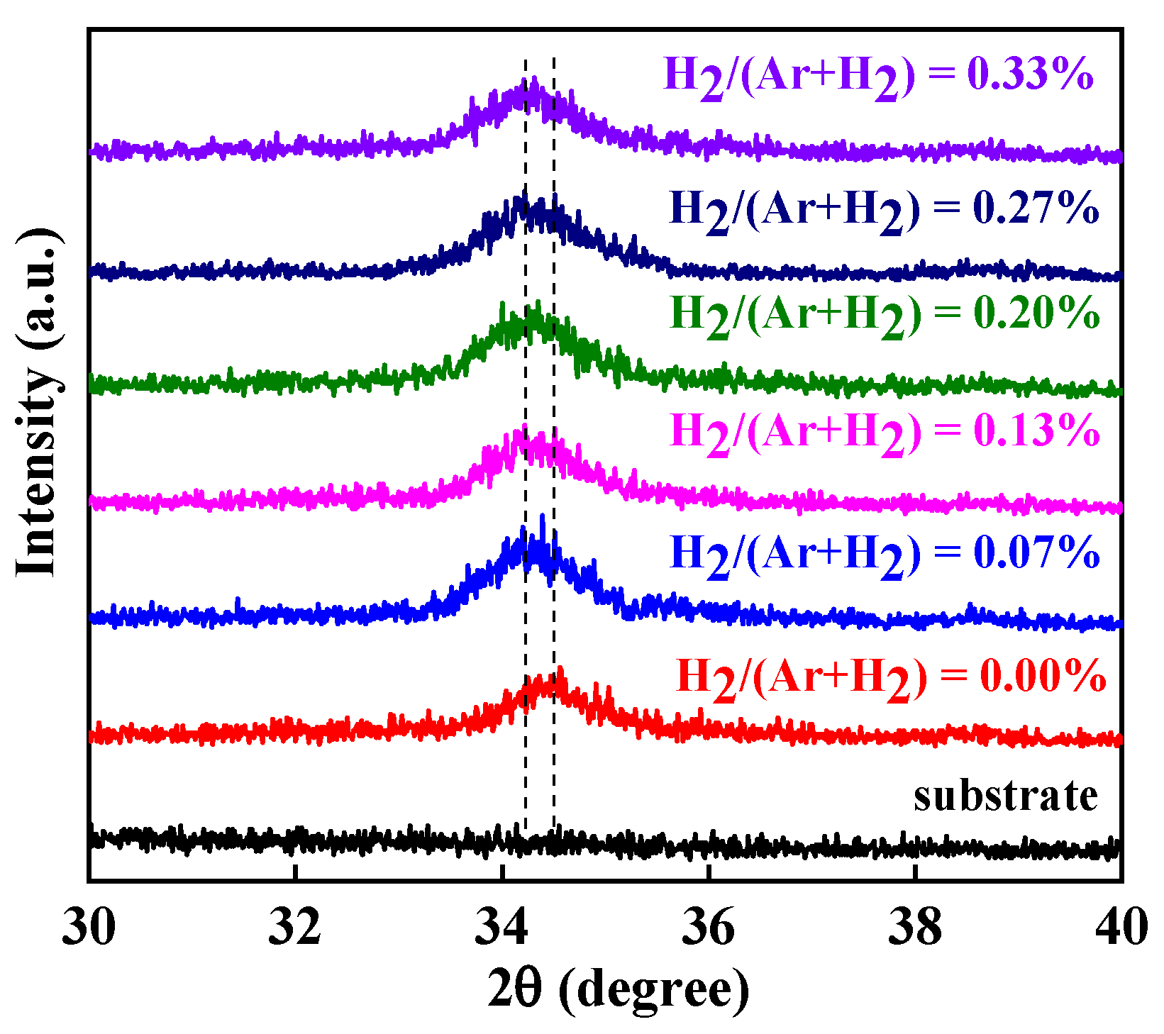
Since the active layers were thin, GIXRD was used to analyze the structure of the ZnO:H/ZnO films, where the front channel layers were prepared with different H2/(Ar + H2) from 0% to 0.33%. As shown in Figure 3, there were only ZnO (002) diffraction peaks for all samples, indicating that all the ZnO:H/ZnO films were hexagonal wurtzite structures with c-axis preferential orientation. Combined with SIMS experimental results, H doping in ZnO lattice was realized. The weak intensity and wide full-width at half-maximum (FWHM) of the diffraction peaks exhibit that the crystalline quality of all films was poor and the grain size was small, which is possibly because the substrates were not intentionally heated. Additionally, the FWHM of the film without hydrogen doping was narrower than those of all the H-doped films, showing that the addition of H2 in the sputtering gas reduced the grain size and increased the grain boundaries, which may be due to the influence of H doping on the nucleation process in film crystallization [14]. We can see from the dotted line mark in Figure 3 that the (002) diffraction peak slightly shifted to a lower angle with increasing H2/(Ar + H2). It is known from the Bragg equation that this was caused by the increase in interplanar spacing. Since part of the doped H existed in the form of hydrogen interstitials (Hi), Hi were located at the center of Zn-O bonds, resulting in the increase in interplanar spacing of c-axis direction [23]. The lattice distortion induced by the H incorporation may also be the reason for the larger FWHM of the H-doped ZnO:H/ZnO films [14]. In comparison, the diffraction peak of a single ZnO:H active layer shifted more obviously with the hydrogen flow ratio [17]; this may be due to the fact that the thickness of a single ZnO:H active layer was several tens of nanometers, much thicker than the 4 nm ZnO:H film in double active layers in this research. It must be mentioned that the increase in grain boundaries and hydrogen-related defects increase the scattering of carriers in the front channel layer, which adversely affects the devices’ performance.
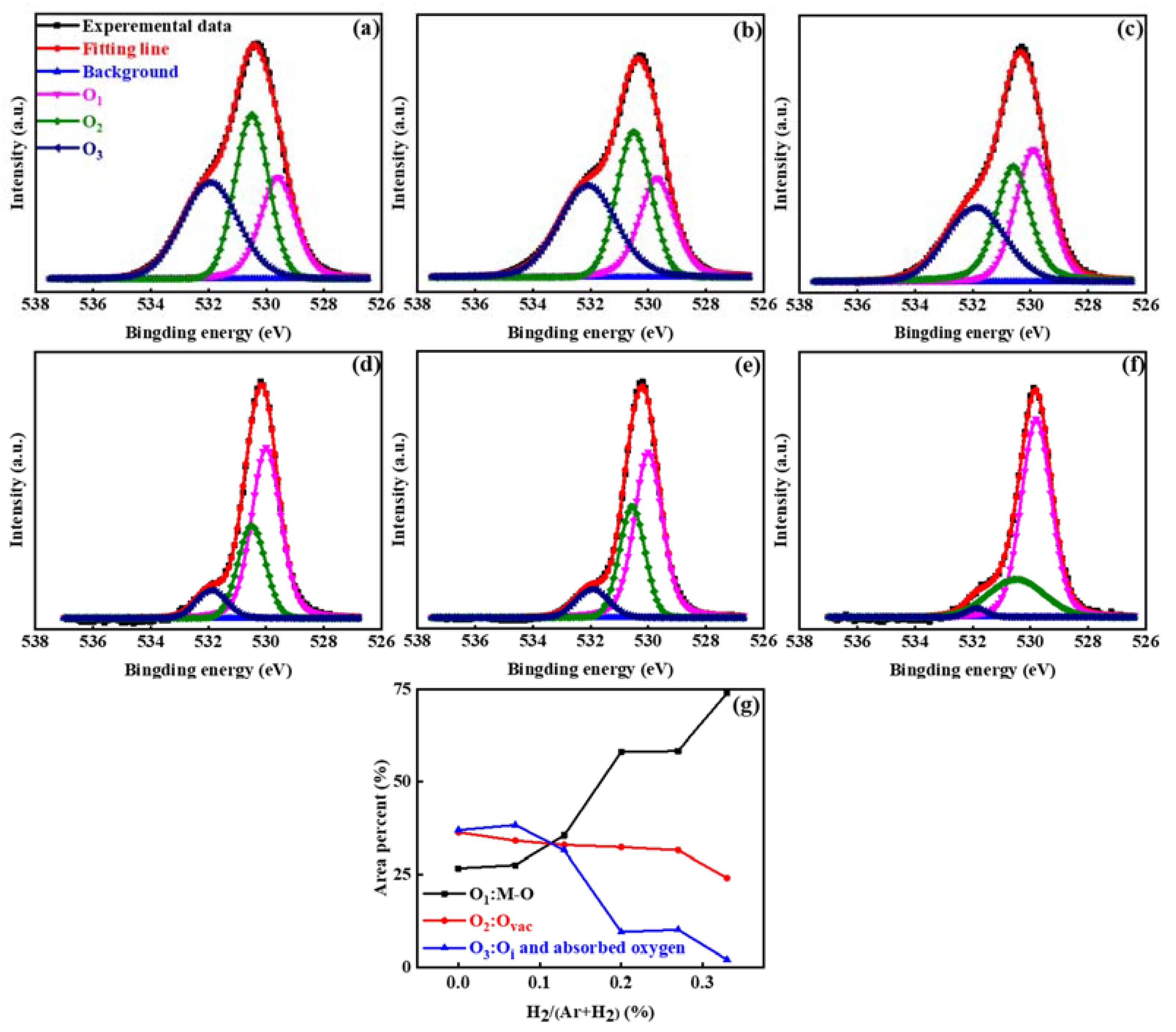
To analyze the effect of H doping on oxygen-related defects in ZnO films, the O 1s energy spectra of ZnO:H films with different H2/(Ar + H2) were obtained by XPS measurement and are shown in Figure 4. The O 1s energy spectra were calibrated by using 285 eV C 1s binding energy as the standard in order to compare the measured O 1s binding energy with the data from the NIST database and other references. As exhibited in Figure 4a–f, the fitting results consist of three components of oxygen in varying chemical states [24,25,26,27]. The fitting peak at 529.8 ± 0.2 eV is related to the O2− in metal oxide, representing the lattice oxygen existing in the Zn-O bonds, marked as O1. The fitting peak at 530.7 ± 0.2 eV is associated with O2− ions in the oxygen-deficient regions within the matrix of ZnO, and the peak intensity reflects the change of oxygen vacancy (VO) content, marked as O2. The fitting peak at 531.9 ± 0.2 eV is attributed to the loosely bound oxygen in ZnO, including oxygen interstitials (Oi) and adsorbed oxygen [28], marked as O3. From the integrated intensities of three fitting peaks, the proportion of three oxygen components can be obtained according to Equation (1).
O x = O x O 1 + O 2 + O 3 × 100 %
From Figure 4g, it is found that the proportion of lattice oxygen was much lower and the proportion of oxygen-related defects was much higher in the undoped ZnO film. With the increase in H2/(Ar + H2), the former significantly increased and the latter obviously decreased. The decrease in VO is attributed to the formation of H-VO complexes (HO), and the decrease in Oi and adsorbed oxygen is due to the passivation effect of hydrogen on the films’ surface and interface [29,30,31,32,33]. The change in oxygen-related defect states with H2 flow ratio will certainly affect the devices’ performance, which will be discussed later.
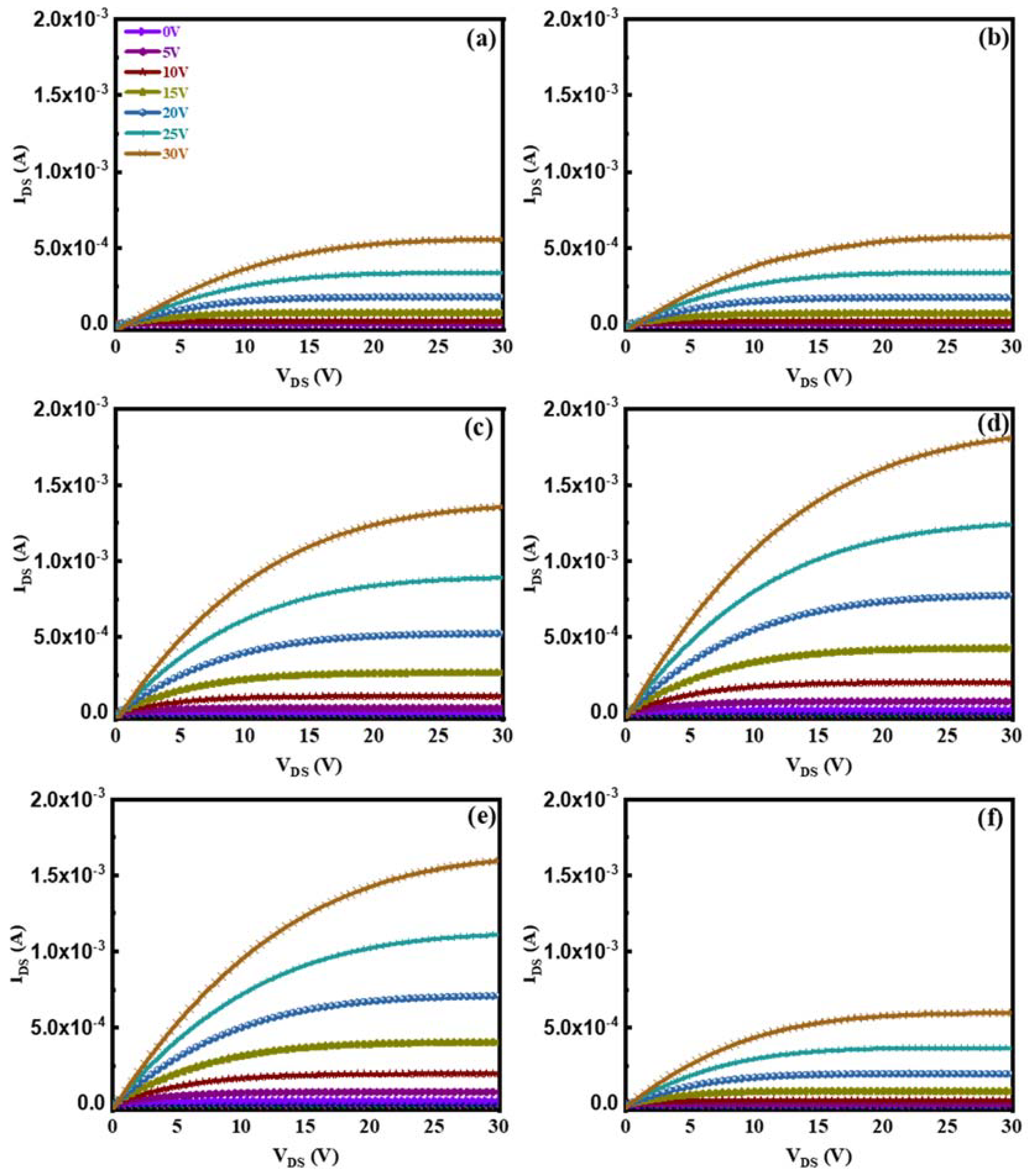
The output curves of our devices fabricated with different H2 flow ratios are shown in Figure 5. All the devices exhibit n-type TFT output characteristics without any current crowding, reflecting good ohmic contact between the active layers and the source/drain electrodes. The output curves of all ZnO:H/ZnO-TFTs show obvious pinch-off and source-drain current saturation, indicating that the devices have good switching characteristics and reach the saturation mode under test conditions. Compared with the undoped device, all H-doped devices exhibit higher Ion. With increasing H2/(Ar + H2), Ion first increases and then decreases. When VDS = 30 V and VGS = 30 V, Ion is 5.55 × 10⁻⁴ A for the undoped device; it reaches a maximum value of 1.81 × 10⁻³ A for the device with H2/(Ar + H2) = 0.20%, more than three times higher than that of the former. Additionally, it decreases to 5.97 × 10⁻⁴ A for the device with H2/(Ar + H2) = 0.33%, similar to that of the undoped device.
Figure 6 shows the transfer curves and the corresponding IDS1/2-VGS curves of our devices fabricated with different H2 flow ratios. The characteristic parameters of the devices extracted from Figure 6 are listed in Table 1, including saturation mobility (μsat), on/off ratio (Ion/Ioff), threshold voltage (Vth), and sub-threshold swing (SS). As shown in Table 1, all devices exhibit good comparable SS values. With the increase in H2/(Ar + H2), μsat and Ion/Ioff increase first and then decrease, while Vth shows the opposite change. That is, the devices’ performance first becomes better and then worse. When H2/(Ar + H2) = 0.13%, ZnO:H/ZnO-TFT with the best performance parameters was obtained: μsat = 12.10 cm2/Vs, Ion/Ioff = 2.32 × 10⁷, SS = 0.67 V/Dec, Vth = 1.68 V. With the further increase in H2/(Ar + H2), the devices’ performance became worse.
According to the above characterization, on the one hand, the oxygen-related defects in the front channel layer (ZnO:H film) decrease with the increase in H2/(Ar + H2), i.e., the trap sites and electron scattering at the dielectric/active layer interface decrease, which facilitates the transport of electrons in the channel. Moreover, the decrease in adsorbed oxygen and Oi as acceptors and the increase in HO and Hi as donors lead to an increase in carrier concentration in the channel [29,30,31,32,33]. The above factors improve the performance of ZnO:H/ZnO-TFT. On the other hand, hydrogen doping induces the increase in grain boundaries and hydrogen-related defects in ZnO:H film, and the scattering of electrons is enhanced in the channel. These factors deteriorate the performance of ZnO:H/ZnO-TFT. When H2/(Ar + H2) is relatively small, the former factors dominate, and the devices’ performance becomes better with the increase in H2 flow ratio. When the H2 flow rate is relatively large, the latter factors dominate, and the device performance becomes worse with increasing H2 flow ratio.
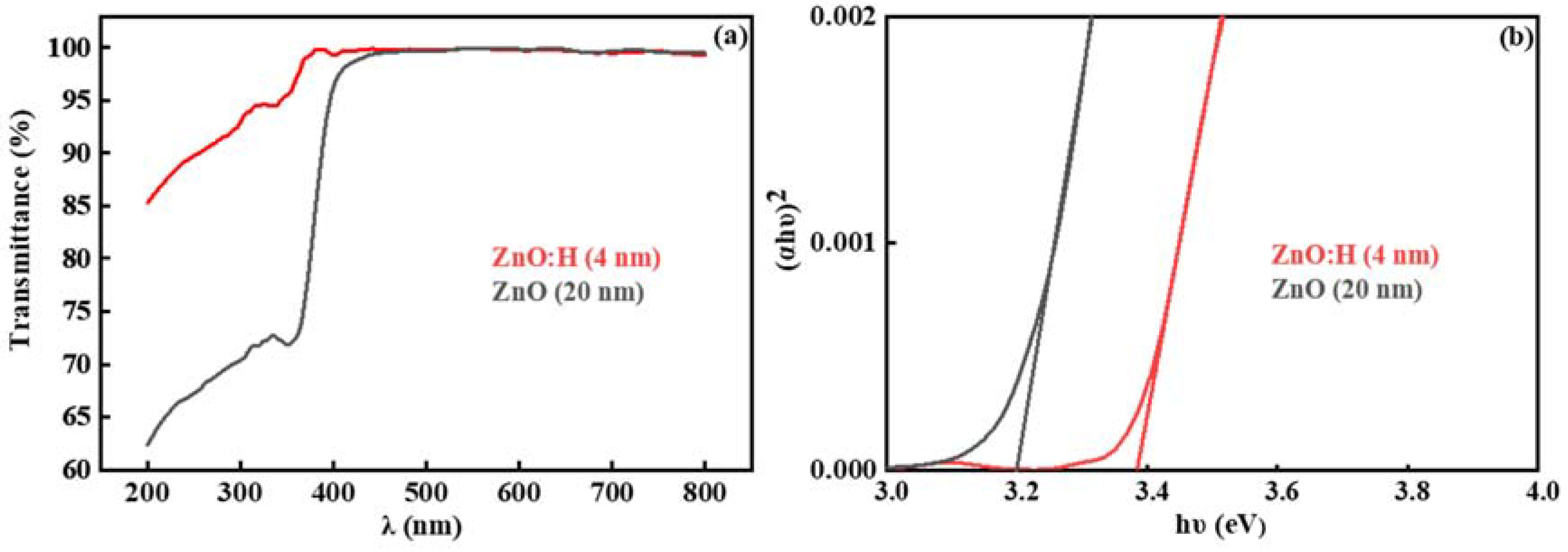
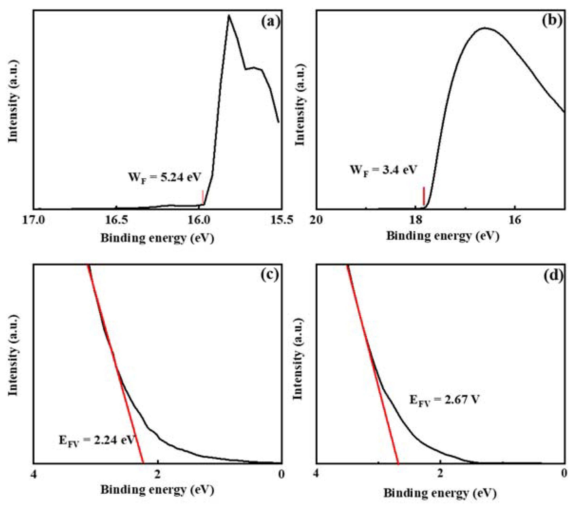
As exhibited in Table 1, compared with the ZnO:H single active layer device with optimal performance fabricated at H2/(Ar + H2) = 0.10% [17], the ZnO:H/ZnO double active layer devices in this paper have significantly improved performance. In the previous study, the single-layer ZnO:H films were much thicker (50 nm), and the number of carriers in the active layers increased significantly due to H doping. When H2/(Ar + H2) = 0.13%, Ioff increased dramatically, Ion/Ioff decreased dramatically, and the devices’ switching performance deteriorated. However, in ZnO:H/ZnO double active layer devices, the number of carriers is relatively limited with the increase in H2/(Ar + H2) due to the much thinner ZnO:H front channel layers. Therefore, we can increase the experimental range of the H2 flow ratio to reduce the carrier scattering by suppressing the oxygen-related defects more effectively. Moreover, due to the adjustment of source-drain resistance by ZnO back channel layers, better performance is obtained in ZnO:H/ZnO-TFTs compared with ZnO:H-TFTs. In addition, the better performance in ZnO:H/ZnO-TFTs may also be related to the interface between ZnO:H and ZnO. It is suggested that due to their different band structures, there exists a potential barrier at the ZnO:H/ZnO interface, which provides an extra carrier transport path for ZnO:H/ZnO-TFTs. In order to explore the carrier transport mechanism in the double active layer devices, the UV-Vis transmission spectra of 4 nm ZnO:H film prepared with H2/(Ar + H2) = 0.13% and 20 nm ZnO film deposited on the sapphire substrates were measured, and the corresponding results are exhibited in Figure 7a. The films’ optical bandgaps (Eg) can be further obtained by the function relationship curves of (αhν)2-, as exhibited in Figure 7b. The obtained Eg was 3.20 and 3.38 eV for ZnO and ZnO:H films, respectively. Figure 8 shows the UPS results of ZnO and ZnO:H films. The difference between the excitation source energy (He I: 21.2 eV) and the cut-off value of high binding energy is the work function (WF) of the material [18]. For ZnO and ZnO:H films, WF = 5.24 and 3.40 eV, respectively. The slope of the cut-off edge of low binding energy represents the energy difference (EFV) between the Fermi level (EF) and the valence band top (EV) [18]. EFV = 2.24 and 2.67 eV for ZnO and ZnO:H films, respectively. Based on the above results, the band structures of ZnO (20 nm) and ZnO:H (4 nm) thin films before contact can be obtained, as shown in Figure 9a. Due to the high lattice matching between ZnO and ZnO:H films, we ignore the influence of surface states on the contact barrier. After contact, due to their different Fermi levels, the electrons in ZnO:H flow to ZnO, and the generated built-in electric field causes the band bending at the interface. The band structure when the equilibrium state is reached is exhibited in Figure 9b. According to Figure 9b, the electrons flowing from ZnO:H to ZnO accumulate at the interface of the ZnO layer close to the ZnO:H layer, and the existence of energy valley limits the dimension of electron movement, providing an additional path for carrier transport in ZnO:H/ZnO-TFTs. Due to the existence of double transport interfaces between dielectric and active layers and between ZnO:H and ZnO layers, the device performance of ZnO:H/ZnO-TFTs has been improved significantly compared with that of ZnO:H-TFTs.

4. Conclusions

Our research shows that the combination of a simple hydrogen doping process and double active layer design can significantly improve the performance of ZnO-based TFTs. H doping in the front channel layer can effectively reduce the scattering of carriers while increasing the carrier concentration. More importantly, the interface between ZnO and ZnO:H provides an additional path for carrier transport. The optimized device exhibits μsat of 12.10 cm2/Vs, Ion/Ioff of 2.32 × 10⁷, SS of 0.67 V/Dec, and Vth of 1.68 V. In this study, there is no heat treatment operation in the whole process of device fabrication, which is helpful for the devices’ subsequent application in the field of flexible electronics.

Author Contributions

Conceptualization, D.Z.; data curation, D.W. and Z.J.; formal analysis, D.W., Z.J. and L.L.; funding acquisition, D.Z. and C.W.; supervision, D.Z. and C.W.; writing—original draft, D.W and Z.J.; writing—review and editing, D.Z., C.W., S.H., M.F., X.L., W.L., P.C. and Y.L. All authors have read and agreed to the published version of the manuscript.

Funding

This work was supported by the National Natural Science Foundation of China (Grant Nos. 12074263, 11774241, and 51872187) and the Shenzhen Science and Technology Innovation Commission (Grant Nos. 20220809104426003 and 20220809152330002).

Data Availability Statement

Data is available from the corresponding authors upon request.

Conflicts of Interest

The authors declare no conflict of interest.

References

  1. Nomura, K.; Ohta, H.; Takagi, A.; Kamiya, T.; Hirano, M.; Hosono, H. Room-temperature fabrication of transparent flexible thin-film transistors using amorphous oxide semiconductors. Nature 2004, 432, 488–492. [Google Scholar] [CrossRef] [PubMed]
  2. Fortunato, E.; Barquinha, P.; Martins, R. Oxide semiconductor thin-film transistors: A review of recent advances. Adv. Mater. 2012, 24, 2945–2986. [Google Scholar] [CrossRef] [PubMed]
  3. Yu, X.; Zhou, N.; Smith, J.; Lin, H.; Stallings, K.; Yu, J.; Marks, T.J.; Facchetti, A. Synergistic approach to high-performance oxide thin film transistors using a bilayer channel architecture. ACS Appl. Mater. Interfaces 2013, 5, 7983–7988. [Google Scholar] [CrossRef]
  4. Park, C. Improvement of the performance and stability of oxide semiconductor thin-film transistors using double-stacked active layers. IEEE Electron. Device Lett. 2012, 33, 818–820. [Google Scholar] [CrossRef]
  5. Presley, E.; Munsee, L.; Park, H.; Hong, D.; Wager, F. Tin oxide transparent thin-film transistors. J. Phys. D Appl. Phys. 2004, 37, 2810–2813. [Google Scholar] [CrossRef]
  6. Noh, H.; Ryu, Y.; Jo, J.; Kim, J. Indium oxide thin-film transistors fabricated by RF sputtering at room temperature. IEEE Electron. Device Lett. 2010, 31, 567–569. [Google Scholar] [CrossRef]
  7. Prins, M.; Grosse, O.; Müller, G.; Cillessen, M. A ferroelectric transparent thin-film transistor. Appl. Phy. Lett. 1996, 68, 3650–3652. [Google Scholar] [CrossRef]
  8. Cai, G.; Qiang, L.; Yang, P. High-sensitivity pH sensor based on electrolyte-gated In2O3 TFT. IEEE Electron. Device Lett. 2018, 39, 1409–1412. [Google Scholar] [CrossRef]
  9. Kim, W.; Moon, Y.; Kim, K.; Shin, Y.; Park, W. Improvement in the bias stability of tin oxide thin-film transistors by hafnium doping. Thin Solid Films 2012, 520, 2220–2223. [Google Scholar] [CrossRef]
  10. Huh, S.; Yang, B.; Oh, S.; Lee, J.; Yoon, K.; Jeong, K.; Hwang, C.; Kim, H. Improvement in the performance of tin oxide thin-film transistors by alumina doping. Electrochem. Solid-State Lett. 2009, 12, H385–H387. [Google Scholar] [CrossRef]
  11. Chin, A.; Cheng, C.; Li, K.; Wu, R.; Chen, Z.; Lu, S.; Lee, L. Electrical properties of modulation doped rf-sputtered polycrystalline MgZnO/ZnO heterostructures. J. Phys. D Appl. Phys. 2011, 44, 455101. [Google Scholar] [CrossRef]
  12. Huang, C.; Chin, H.; Wu, Y.; Cheng, I.; Chen, J.; Chiu, K.; Lin, T. Mobility enhancement of polycrystalline MgZnO/ZnO thin-film layers with modulation doping and polarization effects. IEEE Trans. Electron. Devices 2010, 57, 696–703. [Google Scholar] [CrossRef]
  13. Wang, S.; Li, S.; Cheng, C. Mobility enhancement in RF-sputtered MgZnO/ZnO heterostructure thin-film transistors. IEEE Trans. Electron. Devices 2016, 63, 1545–1549. [Google Scholar] [CrossRef]
  14. Magari, Y.; Kataoka, T.; Yeh, W.; Furuta, M. High-mobility hydrogenated polycrystalline In2O3 (In2O3:H) thin-film transistors. Nat. Commun. 2022, 13, 1078. [Google Scholar] [CrossRef]
  15. Kim, Y.; Park, H.; Kim, G. Effect of photochemical hydrogen doping on the electrical properties of ZnO thin-film transistors. J. Alloys Compd. 2018, 732, 300–305. [Google Scholar] [CrossRef]
  16. Xu, L.; Chen, Q.; Liao, L.; Liu, X.; Chang, T.; Chang, K.; Tsai, T.; Jiang, C.; Wang, J.; Li, J. Rational hydrogenation for enhanced mobility and high reliability on ZnO-based thin film transistors: From simulation to experiment. ACS Appl. Mater. Interfaces 2016, 8, 5408–5415. [Google Scholar] [CrossRef]
  17. Zhu, D.; Jiang, Z.; Zhang, W.; Yin, D.; Xu, W.; Han, S.; Fang, M.; Liu, W.; Cao, P.; Lu, Y. Room-temperature fabrication of high-performance H doped ZnO thin-film transistors. Mater. Chem. Phys. 2021, 261, 124248. [Google Scholar] [CrossRef]
  18. Faber, H.; Das, S.; Lin, H.; Pliatsikas, N.; Zhao, K.; Kehagias, T.; Dimitrakopulos, G.; Amassian, A.; Patsalas, A.; Anthopoulos, D. Heterojunction oxide thin-film transistors with unprecedented electron mobility grown from solution. Sci. Adv. 2017, 3, 1602640. [Google Scholar] [CrossRef]
  19. Cong, Y.; Han, D.; Dong, C.; Zhang, D.; Zhang, X. Fully transparent high performance thin film transistors with bilayer ITO/Al-Sn-Zn-O channel structures fabricated on glass substrate. Sci. Rep. 2017, 7, 1497. [Google Scholar] [CrossRef]
  20. Khim, D.; Lin, H.; Nam, S.; Faber, H.; Tetzner, K.; Zhang, Q.; Zhang, X.; Anthopoulos, D. Modulation-Doped In2O3/ZnO heterojunction transistors processed from Solution. Adv. Mater. 2017, 29, 1605837. [Google Scholar] [CrossRef]
  21. Abliz, A.; Huang, C.; Wang, J.; Xu, L.; Liao, L.; Xiao, X.; Wu, W.; Fan, Z.; Jiang, C.; Li, J.; et al. Rational design of ZnO:H/ZnO bilayer structure for high-performance thin-film transistors. ACS Appl. Mater. Interfaces 2016, 8, 7862–7868. [Google Scholar] [CrossRef] [PubMed]
  22. Lee, M.; Jo, W.; Kim, J.; Choi, S.; Kwon, M.; Jeon, P.; Facchetti, A. Corrugated heterojunction metal-oxide thin-film transistors with high electron mobility via vertical interface manipulation. Adv. Mater. 2018, 30, 1804120. [Google Scholar] [CrossRef] [PubMed]
  23. Chen, L.; Chen, W.; Wang, J.; Hong, F.; Su, Y. Hydrogen-doped high conductivity ZnO films deposited by radio-frequency magnetron sputtering. Appl. Phys. Lett. 2004, 85, 5628–5630. [Google Scholar] [CrossRef]
  24. Jeong, S.; Lee, J.; Roh, Y. Effects of controlling the interface trap densities in InGaZnO thin-film transistors on their threshold voltage shifts. J. Korean Phys. Soc. 2014, 65, 1919–1924. [Google Scholar] [CrossRef]
  25. Komaru, T.; Shimizu, S.; Kanbe, H.; Maeda, Y.; Kamiya, T.; Fortmann, C.; Shimizu, I. Optimization of transparent conductive oxide for improved resistance to reactive and/or high temperature optoelectronic device processing. Jpn. J. Appl. Phys. 1999, 38, 5796–5804. [Google Scholar] [CrossRef]
  26. Chen, M.; Pei, L.; Sun, C.; Wen, L.; Wang, X. Surface characterization of transparent conductive oxide Al-doped ZnO films. J. Cryst. Growth 2000, 220, 254–262. [Google Scholar] [CrossRef]
  27. Trinh, T.; Nguyen, D.; Ryu, K.; Jang, K.; Lee, W.; Baek, S.; Raja, J.; Yi, J. Improvement in the performance of an InGaZnO thin-film transistor by controlling interface trap densities between the insulator and active layer. Semicond. Sci. Technol. 2011, 26, 085012. [Google Scholar] [CrossRef]
  28. Peng, C.; Lin, C.; Tseng, A.; Lee, L. Characterization of the single and double films consisting of Al, Sc-co-doped ZnO/Al-doped ZnO and Al-doped ZnO/Al, Sc-co-doped ZnO. Surf. Coat. Technol. 2008, 202, 5425–5430. [Google Scholar] [CrossRef]
  29. Janotti, A.; Van de Walle, G. Hydrogen multicentre bonds. Nat. Mater. 2007, 6, 44–47. [Google Scholar] [CrossRef]
  30. Selim, A.; Weber, H.; Solodovnikov, D.; Lynn, G. Nature of native defects in ZnO. Phys. Rev. Lett. 2007, 99, 085502. [Google Scholar] [CrossRef]
  31. Janotti, A.; Van de Walle, G. Fundamentals of zinc oxide as a semiconductor. Rep. Prog. Phys. 2009, 72, 126501. [Google Scholar] [CrossRef]
  32. Singh, A.; Chaudhary, S.; Pandya, K. Hydrogen incorporation induced metal-semiconductor transition in ZnO:H thin films sputtered at room temperature. Appl. Phys. Lett. 2013, 102, 172106. [Google Scholar] [CrossRef]
  33. Zhu, D.; Xiang, H.; Cao, P.; Jia, F.; Han, S.; Liu, W.; Ma, X.; Lu, Y. Influence of H2 introduction on properties in Al-doped ZnO thin films prepared by RF magnetron sputtering at room temperature. J. Mater. Sci. Mater. Electron. 2013, 24, 1966–1969. [Google Scholar] [CrossRef]
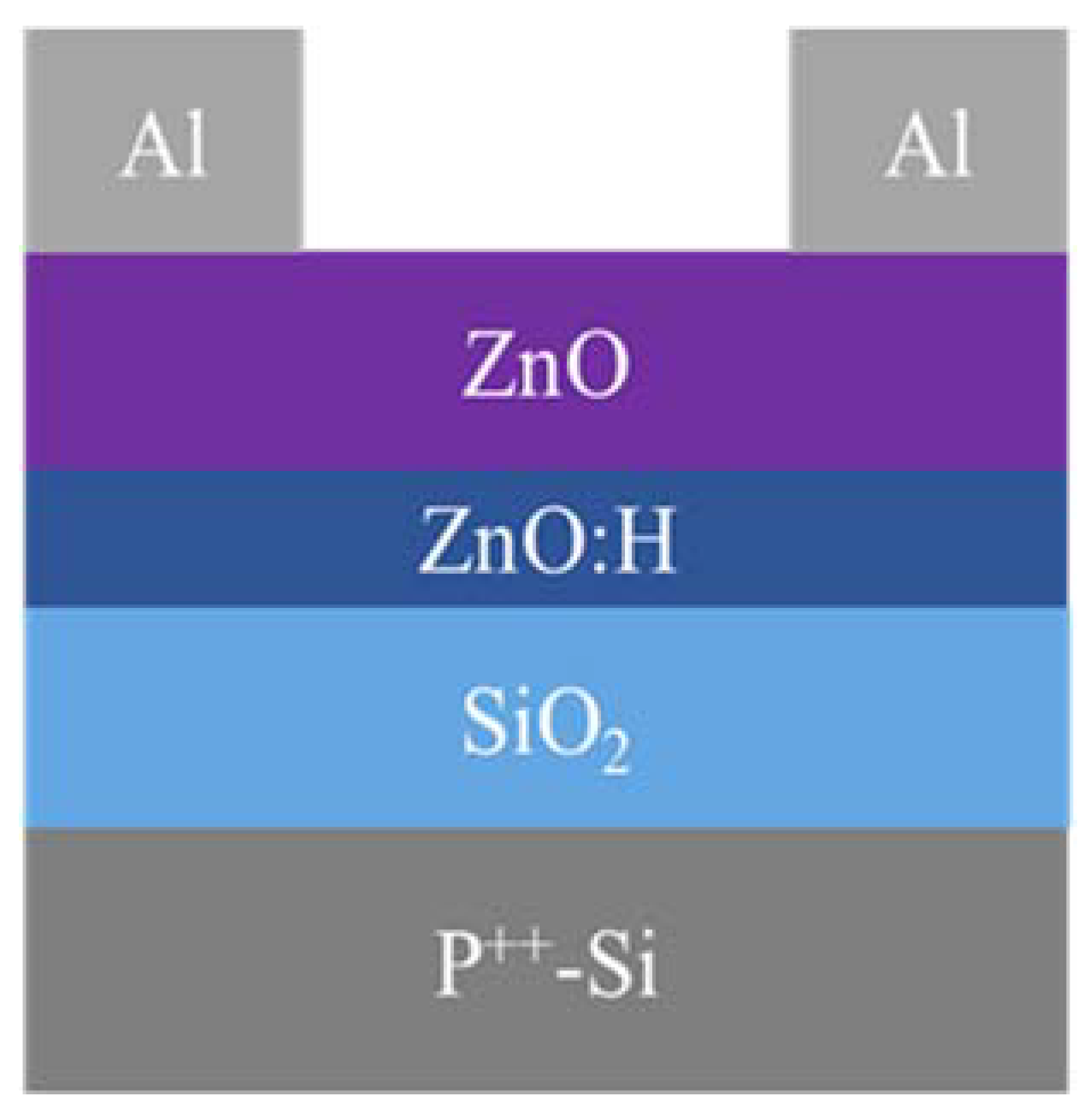
Figure 1. The device structure of bottom-gate top-contact ZnO:H/ZnO-TFT.
Nanomaterials 13 01422 g001
Figure 2. SIMS depth profiles of 20 nm ZnO:H thin film deposited at H2/(Ar + H2) = 0.13%.
Nanomaterials 13 01422 g002
Figure 3. GIXRD curves of ZnO:H/ZnO films prepared with different H2/(Ar + H2).
Nanomaterials 13 01422 g003
Figure 4. XPS spectra of O 1s with different H2/(Ar + H2): (a) 0%, (b) 0.07%, (c) 0.13%, (d) 0.20%, (e) 0.27%, (f) 0.33%; (g) the proportion variation of three oxygen components with H2 flow ratio.
Nanomaterials 13 01422 g004
Figure 5. The output curves of ZnO:H/ZnO-TFTs fabricated with different H2/(Ar + H2): (a) 0%, (b) 0.07%, (c) 0.13%, (d) 0.20%, (e) 0.27%, (f) 0.33%.
Nanomaterials 13 01422 g005
Figure 6. The transfer curves and the corresponding IDS1/2-VGS curves of ZnO:H/ZnO-TFTs fabricated with different H2/(Ar + H2).
Nanomaterials 13 01422 g006
Figure 7. (a) UV-Vis transmission spectra and (b) the function relationship curves of (αhν)2- of ZnO:H prepared at H2/(Ar + H2) = 0.13% and ZnO channel layers.
Nanomaterials 13 01422 g007
Figure 8. UPS results near the cut-off edge of high binding energy for (a) ZnO and (b) ZnO:H prepared at H2/(Ar + H2) = 0.13%; UPS results near the cut-off edge of low binding energy for (c) ZnO and (d) ZnO:H prepared at H2/(Ar + H2) = 0.13%.
Nanomaterials 13 01422 g008
Figure 9. The band structures of ZnO and ZnO:H prepared at H2/(Ar + H2) = 0.13%: (a) before contact and (b) after contact.
Nanomaterials 13 01422 g009
Table 1. The device characteristics of ZnO:H/ZnO-TFTs fabricated with different H2/(Ar + H2) and ZnO:H-TFT fabricated at H2/(Ar + H2) = 0.10%.
H2/(Ar + H2) (%)μsat (cm2/Vs)Vth (V)Ion/IoffSS (V/Dec)
06.525.682.19 × 1060.78
0.076.535.417.65 × 1060.68
0.1312.101.682.32 × 1070.67
0.209.880.261.76 × 1070.99
0.279.041.241.47 × 1071.07
0.335.475.357.52 × 1060.84
ZnO:H-TFT [17]5.176.034.98 × 1060.76
Disclaimer/Publisher’s Note: The statements, opinions and data contained in all publications are solely those of the individual author(s) and contributor(s) and not of MDPI and/or the editor(s). MDPI and/or the editor(s) disclaim responsibility for any injury to people or property resulting from any ideas, methods, instructions or products referred to in the content.