Article

Electronic and Optoelectronic Monolayer WSe2 Devices via Transfer-Free Fabrication Method

1
Joint Key Laboratory of the Ministry of Education, Institute of Applied Physics and Materials Engineering, University of Macau, Avenida da Universidade, Taipa, Macao SAR 999078, China
2
International Collaborative Laboratory of 2D Materials for Optoelectronics Science and Technology of Ministry of Education, Institute of Microscale Optoelectronics, Shenzhen University, Shenzhen 518060, China
3
Department of Materials Science and Engineering & Center of Super-Diamond and Advanced Films, College of Engineering, City University of Hong Kong, 83 Tat Chee Avenue, Kowloon, Hong Kong SAR 999077, China
4
Electrical Engineering Division, Engineering Department, University of Cambridge, 9 JJ Thomson Avenue, Cambridge CB3 0FA, UK
*
Authors to whom correspondence should be addressed.
Nanomaterials 2023, 13(8), 1368; https://doi.org/10.3390/nano13081368
Submission received: 9 March 2023 / Revised: 6 April 2023 / Accepted: 12 April 2023 / Published: 14 April 2023

Abstract

:
Monolayer transition metal dichalcogenides (TMDs) have drawn significant attention for their potential applications in electronics and optoelectronics. To achieve consistent electronic properties and high device yield, uniform large monolayer crystals are crucial. In this report, we describe the growth of high-quality and uniform monolayer WSe2 film using chemical vapor deposition on polycrystalline Au substrates. This method allows for the fabrication of continuous large-area WSe2 film with large-size domains. Additionally, a novel transfer-free method is used to fabricate field-effect transistors (FETs) based on the as-grown WSe2. The exceptional metal/semiconductor interfaces achieved through this fabrication method result in monolayer WSe2 FETs with extraordinary electrical performance comparable to those with thermal deposition electrodes, with a high mobility of up to ≈62.95 cm2 V−1 s−1 at room temperature. In addition, the as-fabricated transfer-free devices can maintain their original performance after weeks without obvious device decay. The transfer-free WSe2-based photodetectors exhibit prominent photoresponse with a high photoresponsivity of ~1.7 × 10⁴ A W−1 at Vds = 1 V and Vg = −60 V and a maximum detectivity value of ~1.2 × 10¹³ Jones. Our study presents a robust pathway for the growth of high-quality monolayer TMDs thin films and large-scale device fabrication.

1. Introduction

The emergence of two-dimensional (2D) semiconductors, specifically transition metal dichalcogenides (TMDs), has garnered significant interest in high-performance electronic devices due to their unique transition from indirect to direct band gaps when reducing the number of layers to one [1,2,3]. For example, bulk WSe2 is a p-type semiconductor with an indirect band gap of ~1.2 eV, while monolayer WSe2 has a direct band gap of ~1.65 eV, making it suitable for its optoelectronic applications [4]. Though exfoliated WSe2 has been used to fabricate high-performance p-type field-effect transistors (FETs) [5], the mechanical exfoliation method limits the size of monolayer semiconductors to a few tens of micrometers. Compared to mechanical cleavage and liquid exfoliation, chemical vapor deposition (CVD) is a well-developed method for growing large-area monolayer TMDs on various substrates, which provides a great potential to obtain van der Waals (vdW) contacts with metals such as graphene grown on Cu (111) film [6] and hBN grown on Cu (110) film [7]. Gao and co-workers demonstrated an ultrafast growth method for producing high-quality WSe2 with millimeter-size single-crystal domains on Au foils [8]. Another study showed that researchers can grow single-crystal TMD films on a centimeter scale using the atomic sawtooth gold surface [9]. Furthermore, it has been reported that Au can form vdW interfaces with TMDs due to its good chemical stability in a chalcogen-rich environment [10]. However, the aforementioned monolayer WSe2 needs to be transferred onto the dielectric layer for device fabrication, which rises significant issues with cracks, wrinkles, interfacial contamination and transfer size limitation [11,12]. Furthermore, the removal of supporting polymer films, such as poly (methyl methacrylate) (PMMA) usually requires aggressive chemical treatments, resulting in unavoidable contamination on 2D material surfaces and undesirable device performance [13].
Here, we present a large-scale CVD method for growing monolayer WSe2 on Au foil with an area of up to 1 cm2. We also demonstrate a transfer-free fabrication method for field-effect transistors (FETs) using this monolayer thin film. The spectroscopic and microscopic studies reveal the excellent crystalline quality of the atomically thin WSe2. By applying a novel transfer-free fabrication method, vdW integration of Au electrode remains, further FIB-STEM revealing the fine contact and clean interface between metals and 2D semiconductors. Based on this, we observed a robust and consistent p-type characteristic in monolayer WSe2, and electrical transport studies further demonstrate that the p-type WSe2 FETs exhibit excellent electronic characteristics compared to those with evaporated Au electrodes. Optoelectronic characterizations also show prominent photoresponse, with high photoresponsivity and detectivity in photodetectors fabricated by our novel transfer-free method.

2. Experimental Section

2.1. Au Foil Preparation

The preparation of polycrystalline Au foils follows our previously reported process [14]. To start, commercially available Au foils (Alfa Aesar, Tewksbury, MA, USA, 25 μm thickness, 99.985% metal basis, LOT: R23F014) were cut into an appropriate size (≈1 cm2). Then, small pieces of Au foils were ultrasonically cleaned with an acetone solution and Isopropyl alcohol (IPA) solution for 10 min, respectively. Afterwards, the cleaned Au foils were annealed in the CVD furnace (Kejing, Hefei, China) at 1000 °C for 3 h to release the stress and expose the grain boundaries. Ar with a flow rate of 100 sccm was kept throughout the whole annealing process.

2.2. CVD Growth Process of Monolayer WSe2

The as-prepared polycrystalline Au foil was placed on a self-designed flattened quartz plate and surrounded by WO3 powder (Sigma, St. Louis, MO, USA) (99.9%, 10 mg) (Figure S1a). The plate was then loaded onto a quartz boat and placed at the centre of the heating zone. Selenium powder (99.9%, 20 mg) (Alfa Aesar, Shanghai, China) was put into another boat upstream outside the furnace. The temperature was raised to 900 °C and kept at 900 °C for 10 min to initiate the growth of the WSe2 monolayer on Au foil. At last, the furnace was cooled down to room temperature slowly. The H2 flow rate was only supplied with 4 sccm during the 10 min growth process, and Ar was used as the carrier and protective gas with a flow rate of 80 sccm throughout the process.

2.3. Transfer WSe2 Film to SiO2/Si Substrate

Poly methyl methacrylate (PMMA) (Aladdin, Shanghai, China) (10 wt.%, in anisole) was spin-coated at 2000 rpm for 60 s and then was baked at 180 °C for 5 min. The PMMA–WSe2–Au foil was then placed in the Au etchant solution (I2 and KI in a mol ratio of 1:1, dissolved in 50 mL deionized (DI) water) at 50 °C for 1 h to ensure the complete removal of Au foil. After that, the floating film was transferred into DI water to remove the etchant ions and was finally lifted onto a cleaned SiO2/Si substrate. The substrate was then dipped into acetone to remove the PMMA layer.

2.4. Device Fabrication

After the CVD growth process, 5% PMMA (350-k PMMA dissolved in ethyl lactate) was first coated onto WSe2 film using spin-coating at 2500 rpm for 40 s and then baked at 180 °C for 5 min. The photoresist was spin-coated onto Au foil on the side without monolayer WSe2 film at 3500 rpm for 40 s and baked at 130° for 3 min. A pattern, as shown in Figure S1b, was designed by CleWin 5.0 (2019, version5.0, WieWeb software, Hengelo, The Netherlands) with a 100 μm channel (exposed part) and 450 μm electrode width (remaining part). The sample was exposed using a laser writer (MicroWriter ML 3, Durham Magneto Optics Ltd., London, UK). The exposed photoresist was developed by NMD-3 (Tokyo Ohka Kogyo Co., Ltd., Tokyo, Japan) for 30 s and rinsed in DI water for another 30 s. After that, the ethyl lactate solution was spin-coated at 1000 rpm for 30 s to form a uniform solution film on the surface of the SiO2/Si substrate, followed by rapidly attaching it to the PMMA side and baking at 120 °C for 30 min to obtain the sandwich structure. Next, the Au etchant solution was used to etch away the exposed part of Au by floating the substrate on the Au etchant, resulting in a specific-length WSe2 channel. Finally, the overlying photoresist on Au was removed by N-methyl-2-pyrrolidone (NMP) vapor treatment. The comparison devices were fabricated using WSe2 CVD-grown on SiO2/Si, with 100 nm Au electrodes deposited using masks via the thermal deposition system (PRO Line PVD 75, Shanghai, China).

2.5. Characterization

The optical images were obtained using a microscope (Leica DM2700M RL, Wetzlar, Germany). Atomic force microscopy characterization was performed on a Bruker Dimension ICON microscope (365 Boston Rd., Billerica, MA, USA). Raman and Photoluminescence spectra were collected using a Raman spectroscope (Alpha 300, WITec with 532 nm laser, Lise-Meitner-Str., 6 D-89081 Ulm, Germany) and Transmission Electron Microscope images were analyzed by TEM (JEM-3200FS, JEOL, Street No. 6, Haidian District, Beijing, China). The electrical and optoelectronic characteristics of devices were measured using a Keithley 4200 semiconductor characterization system connected to a Lakeshore cryogenic probe station under vacuum conditions. A supercontinuum spectrum white light laser (SC400-8, Fianium Ltd., Southampton, UK) was used as the light source coupled with a monochromator. The light intensity was studied with a Thorlabs commercial power meter.

3. Results and Discussion

3.1. Synthesis and Characterization of Monolayer WSe2

A monolayer WSe2 film was fabricated using a one-pot CVD process at atmospheric pressure. The synthesis of the monolayer WSe2 film on Au foil is described in the Materials and Methods section in detail. The experiment setup is illustrated in Figure 1a. Note that the Au foil was placed on a specially designed flattened quartz boat, surrounded by WO3 powder, which ensures sufficient supplies and uniform distribution of precursors to form large-scale WSe2 film on polycrystalline Au substrate. The 10 min stage and the slow cooling stage were applied to grow wrinkle-free monolayer WSe2 film. The temperature program used is illustrated in Figure S2a. As shown in Figure S2b, as-grown monolayer WSe2 film on Au foil is continuous and without cracks over a large area.
To confirm the uniformity of the as-grown WSe2 film, spectroscopic analyses are carried out. Given that the laser exciton would lead to an energy transfer from the WSe2 to Au, the as-grown WSe2 film was transferred onto SiO2/Si substrates to accurately characterize the WSe2 structures [8]. The typical Raman spectra (Figure 1b) are obtained from five random positions, as labelled in the optical image shown in the inset. Two obvious characteristic peaks are observed in the region from 249.8 cm−1 to 259.6 cm−1, which can be assigned to E 2 g 1 (in plane) and A1g (out of plane) modes of 2H-WSe2, respectively. Meanwhile, the absence of the B2g peak (which is a fingerprint of few-layer WSe2 and is absent in monolayer WSe2) at ~304 cm–1 suggests that the as-grown WSe2 film is monolayer [15]. In addition, Raman curves are identical to each other, without any detectable difference in peak frequencies, negligible variations in peak intensities and full-width at half-maximum of each peak, which further confirms the consistently good quality over the whole WSe2 film [16]. Moreover, the PL spectra in Figure 1c acquired randomly from five positions also show the same sharp peak at ≈758 nm with a full width at half-maximum of ≈39 nm, a characteristic of direct band gap semiconductors [17]. Figure S3 shows the high-magnification optical microscopic image of the as-grown WSe2 film on SiO2/Si substrate, indicating its uniform optical contrast and lack of adlayers. The few folded areas at the edge of the WSe2 film are due to the transfer process. AFM was applied to further characterize the thickness and morphology properties of the as-prepared WSe2 film. The surface quality of the film is evaluated by calculating the root means square roughness (Rq) over the area shown in Figure S2c, which is 0.425 nm, similar to previously reported values [18]. Figure S2d presents the AFM image of the edge on the WSe2 film and the corresponding height profile acquired along the yellow section dash line. The inset curve displays a real film thickness of ≈0.9 nm, consistent with the value in the literature [16]. All these results indicate that the as-grown WSe2 film on Au foil is a uniform monolayer.
To determine the quality of as-growth WSe2 film, transmission electron microscopy (TEM) and atomic resolution spherical aberration-corrected transmission electron microscopy (ARSTEM) were conducted on the transferred samples. Figure 1d shows a TEM image, indicating that the as-grown monolayer WSe2 film has clear crystalline without obvious defects over a wide dimension range. The corresponding selected area electron diffraction (SAED) pattern is provided in Figure 1e, with two different sets of spots. Additionally, ARSTEM (as shown in Figure 1f) reveals its defect-free atomic lattice, and the two sets of spots ka and kb are broken from the asymmetry of W and Se sublattices in monolayer WSe2. These are ka = {(1100), (1010), (0110)} and kb = −ka marked with blue and orange color rectangles, respectively. The contrast analysis of the diffraction spots (Figure S4) shows that the ka spots are ~8% brighter than the kb spots, which confirms WSe2 is a hexagonal lattice structure with threefold symmetry. Figure 1g is an atomic structure model of monolayer WSe2 corresponding to STEM results. Two different orientations determine the distance between two adjacent W atoms: one is the zigzag direction (ZZ) and the other is the armchair direction (AC), highlighted with green and red dash lines, respectively. In theory, the ratio of the distance along AC (Dac) and the distance along the ZZ (Dzz) should be 3 . Since the intensity of atomic brightness is strongly dependent on the atomic number with an exponential relationship, two random zooms that contain W atoms were selected to study the intensity evolution in the defined direction ZZ and AC with the green and red rectangles marked in Figure 1f. It is clear that the Dzz = 0.338 nm and Dac = 0.585 nm for two adjacent W atoms along two labelled orientations, respectively. The experimental ratio of Dac and Dzz is about 1.73 and the result is in line with the theoretical values mentioned above, proving that as-grown monolayer WSe2 film exhibits very high crystalline quality.

3.2. Design of the Transfer-Free Monolayer WSe2-Based Device

Since Au is a very good conductor, a novel transfer-free technology route is demonstrated, where the field effect transistors are directly fabricated without separating CVD-grown TMD materials and metal substrate. Our result shows that Au foil could be used as electrodes (source and drain) for field-effect transistors.
The schematic illustration of the transfer-free FET device fabrication process is presented in Figure 2a. The detailed parameter is described in the experimental section. The uniform monolayer WSe2 film on Au foil is used directly after CVD growth without further post-treatment. First, PMMA layer as a supporting scaffold is spin-coated on the WSe2 surface to protect the material before the subsequent process. Then, the as-processed flake is reversed, with the blank Au foil side facing up and coated with the photoresist. Thus, a sandwich structure is constructed, composed of a photoresist layer, Au foil, monolayer WSe2 film and PMMA layer. The top view pictures of the structure corresponding to the different stages are labelled with different colored rectangle marks, as shown in Figure S5. The ethyl lactate solution is then spin-coated onto a heavily doped silicon substrate with 300 nm silicon oxide, which rapidly sticks with the PMMA side on the as-processed sandwich component. After that, a photoresist layer is patterned and exposed via laser writer, followed by the application of Au etchant solution to etch away the exposed part of Au and form the device electrodes. Finally, the photoresist on Au electrodes is removed by N-methyl-2-pyrrolidone (NMP) vapor and the FET device with the specific channel length can be successfully fabricated, leading to an ideal metal/semiconductor interfaces at the drain and source with less diffusion, defeats, chemical bonding and strain, as previously demonstrated using conventional electron beam lithography and high-vacuum thermal deposition [19,20]. A high-resolution cross-sectional TEM image in Figure 2b displays the interface structure of as-prepared FET device. In addition, cross-sectional TEM measurements exhibit the elemental distributions of Au, W and Se in the Au/WSe2 interface, and it is observed that Se does not invade the polycrystalline Au surface. It should be noted that Se and W distribution length shown is relatively larger than the real value due to the long-time integration process of images. Furthermore, FIB-STEM images of WSe2 on Au foil (as shown in Figure S6) confirm an intact WSe2 monolayer attached to the Au foil surface, indicating the uniform epitaxial growth of WSe2 on the gold foil surface as well as sharp and clean WSe2/Au interface.

3.3. Electrical and Optoelectronic Properties of the WSe2-Based Device

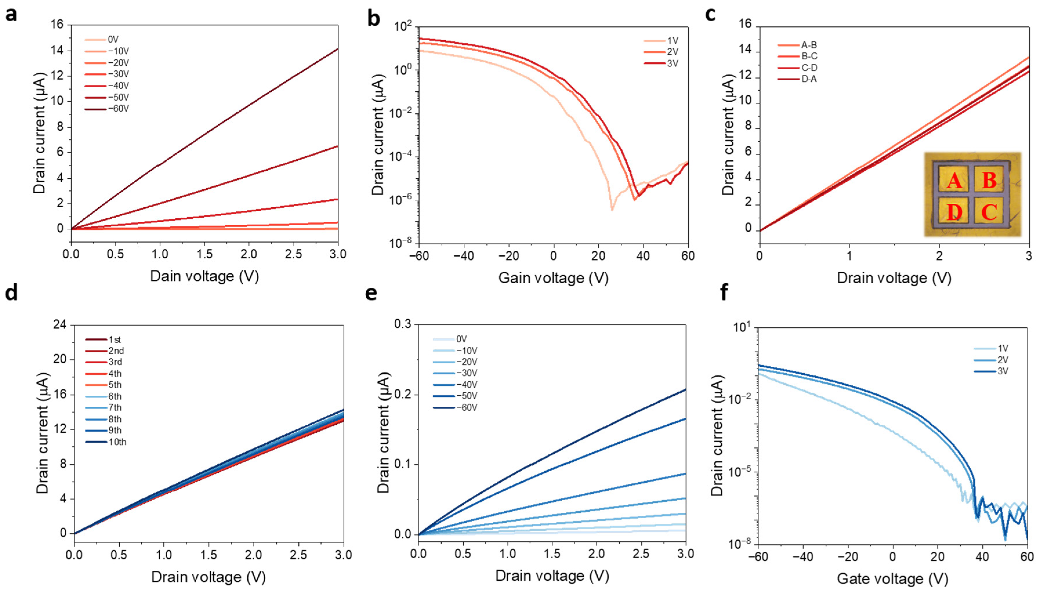
The electronic properties of the as-fabricated transfer-free WSe2 FETs are evaluated, and standard measurements are conducted under ambient conditions to obtain the device performance. Figure 3a presents the Ids-Vds output characteristic of the device at various gate voltages, with linear curves shown suggesting that ohmic-like contacts are formed between the Au electrodes and the underneath WSe2. With Vds bias, when the gate voltage is equal to zero (OFF working state), the current is limited by the barrier between the Au electrodes and monolayer WSe2. However, when a sufficient negative back-gate voltage is applied (ON working state), more holes can be transported due to the lower barrier as the Fermi level is shifted down to near the valence band of WSe2. As shown in Figure 3b, the Ids-Vg transfer characteristic is obtained at different drain biases from 1 to 3 V, with the back-gate voltage sweeping from −60 to 60 V. These transfer curves indicate typical p-type semiconductor characteristic of CVD-grown monolayer WSe2 with direct Au metal contact. In addition, when a 1 V bias is applied between drain and source, the corresponding ON/OFF ratio is about 2 × 10⁶, and on current (Ion) it is as high as 7.84 × 10⁻⁶ A. The field effect mobility can be calculated using following equation:
μ = dI ds / dV g × L / ( WC i V ds
where L is the channel length, W is the channel width, and C i   is the gate capacitance. Apart from 300 nm-thick SiO2 (1.15 × 10⁻⁸ F cm−2), 150 nm-thick PMMA is also taken into consideration [21] (thickness is shown in Figure S7). The final value of C i is calculated to be 7.35 × 10⁻⁹ F cm−2. Therefore, the mobility extracted from the transfer curve is around 62.95 cm2 V−1 s−1 when Vds = 1 V. Additionally, devices are measured between different patterned electrodes to demonstrate the film quality, and results in Figure 3c illustrate the good uniformity of as-grown monolayer WSe2 film, which is ready for potential large-scale nanofabrication processes. Moreover, it is worth noting that as-fabricated transfer-free devices can maintain their original performance after weeks as no obvious device decay can be seen in Figure 3d, further suggesting the stability of our transfer-free fabrication approaches. For comparison, another batch of WSe2 FETs is fabricated using conventional electron beam lithography followed by high vacuum thermal deposition, resulting in undesirable output and transfer characteristics, as shown in Figure 3e,f, respectively. Not surprisingly, the evaporated contact device only exhibits mobility of 0.40 cm2 V−1 s−1 when Vds = 1 V. According to a previous study, chemical interaction exists between thermally evaporated Au and WSe2 and thus hampers electrical properties, while the interlayer interaction between transferred Au electrodes and WSe2 is weak, barely impacting the intrinsic semiconducting behaviour [19]. Furthermore, the output current of monolayer WSe2 FETs with Au electrodes thermally deposited suffer significant drop after weeks (seen in Figure S8); the reason could be the poor interface contact between the Au electrodes and the channel TMD material. In our case, devices fabricated via the transfer-free method exhibit much better device performance and stability than that conducted by the conventional evaporation method due to the sharp and clean interface between electrode metal and underneath WSe2.
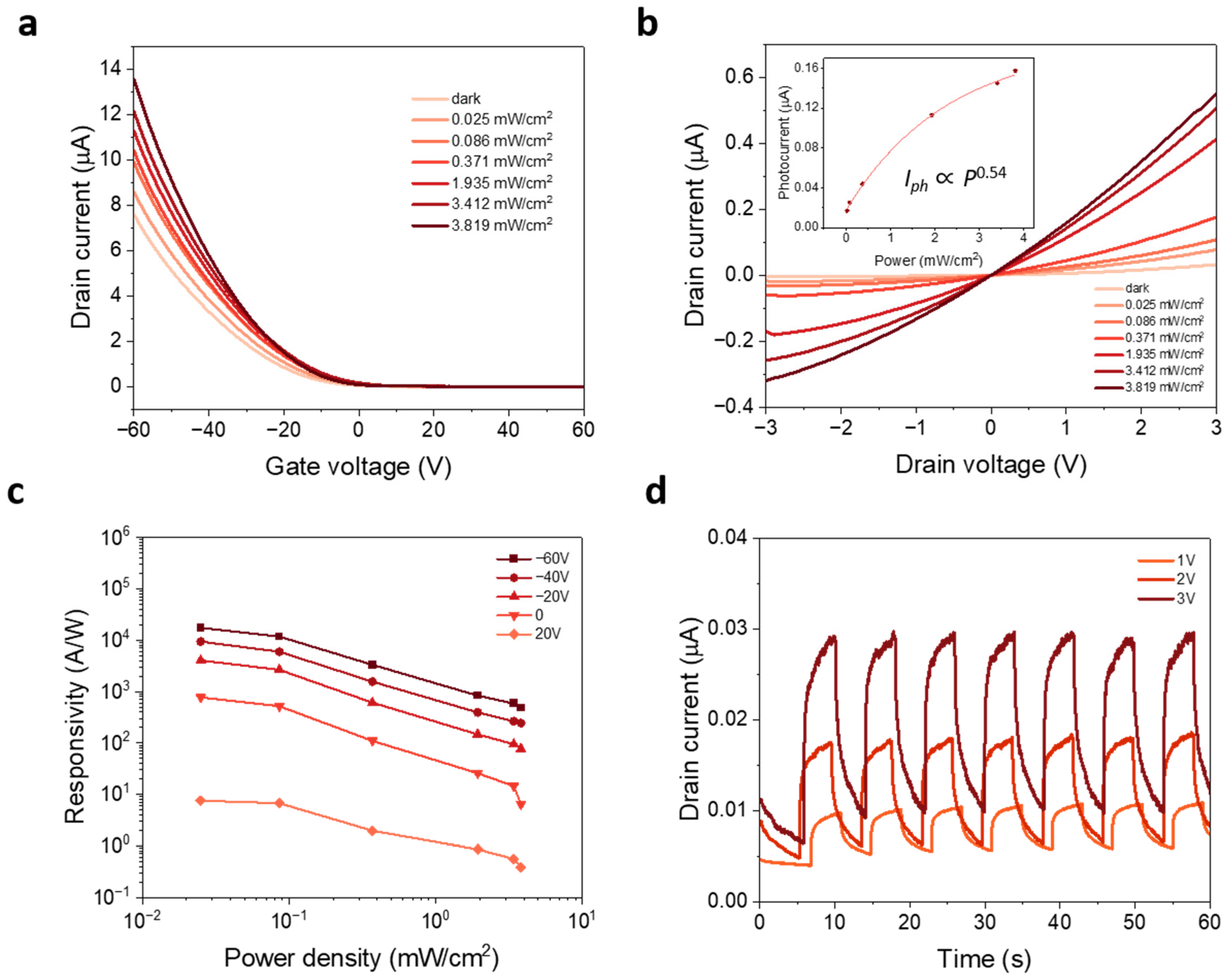
On the other hand, the photoconduction properties of WSe2-based monolayer were investigated by illuminating a 532 nm laser on the device channels, where the optical power P of the laser was varied. Figure 4a depicts the transfer curve of the transfer-free WSe2 device at Vds = 1 V with different illumination power densities. Due to the photogating effect, a higher photocurrent is generated, and Vth is shifted to a more positive gate voltage with stronger illumination power densities. It showed that in the depletion region at the metal/TMDs interface, the depletion region due to the Schottky barrier can extend to several micrometers in the channel [22]. The ohmic-like metal contact leads to narrow depletion region where voltage drop related to adsorbates, defects or charge impurities at interfaces becomes important as the photodesorption or photoexcitation through defect or charge impurity states to band edge may contribute to photocurrents in the ON state [23]. Figure 4b shows the Ids-Vds output characteristic of the device at various laser power densities. The relationship between I ph   and P follows the power law dependence,   I ph P γ , where exponential γ describes the dominant photocurrent generation mechanism. Here, γ is determined to be ~0.54 and this nonlinear relationship discards the photothermoelectric effect as the origin of the observed photoresponse. For WSe2, the nonlinear dependency has been reported to be 0.5, while for other TMDs such as MoS2, the value lies between 0.5 and 0.7 [24].
One of the critical figures of merit for photodetector performance is photoresponsivity R, which is defined as
R =   I ph /   P laser
  I ph is photocurrent, which is defined as
  I ph =   I light   I dark
while   P laser is the laser power. As shown in Figure 4c, when gate voltage shifts to more negative values, the corresponding responsivity values increase significantly, indicating working state switches from OFF to ON. Moreover, photoresponsivity enhancement can be observed with a lower power density, which is derived from the low density of occupied trap states in monolayer WSe2 or at the WSe2/Au interfaces under dim laser illumination [25]. The lower laser power density also results in lesser recombination rate of the photoexcited carrier, improving the photoresponsivity of the device [26]. As a result, a photoresponsivity of ~1.7 × 10⁴ A W−1 is achieved when the photodetector operates at Vds = 1 V and Vg = −60 V, which is comparable to previously reported values [24,27]. The high photoresponsivity indicates the photoinduced electron-hole pairs can be efficiently separated and then transported through sharp and clean WSe2/Au interface to the Au electrodes. Furthermore, to determine the ability of device to detect weak optical signals, the detectivity D * is calculated using the formula D * = RA 1 / 2 / 2 e   I dark 1 / 2 , where R is responsivity, A is the effective device area, e is the elementary charge and   I dark represents the dark current. The D * is calculated to be ~1.2 × 10¹³ Jones for   P laser   ~0.025 mW/cm2 at Vds = 1 V. Note that this detectivity value is comparable to commercial InGaAs photodetectors (1012–1013) [28]. Figure 4d shows the time-dependent photocurrent of a transfer-free monolayer WSe2 device under a power density of 3.06 mW/cm2 at different Vds. The magnitude of photocurrent increases as the drain voltage rises from 1 V to 3 V. The photocurrent reaches the peak value with 532 nm incident light illumination, as shown in Figure S9a, which is measured under a power density of 3.06 mW/cm2 at Vds = 1 V. As presented in Figure S9b, the response and recovery times are measured to be 0.7 s and 2.4 s, respectively. Generally speaking, for a photodetector, there is a trade-off between high responsivity and fast response [27]. These relatively slow responses and recovery behaviors presumably occur due to long device channel length.

4. Conclusions

In conclusion, we have demonstrated the growth of high-quality uniform monolayer WSe2 by CVD using polycrystalline Au as substrates. Spectroscopic and microscopic studies reveal the excellent crystalline quality of monolayer WSe2 within a centimeter-size scale, enabling the potential for large-scale optoelectronic applications. By applying a novel transfer-free fabrication method, the sharp and clean interface between monolayer WSe2 and Au maintains, which provides WSe2 FETs with much better electrical properties when compared to those with thermally deposited Au drains and sources. Moreover, the transfer-free WSe2-based photodetectors exhibit prominent photoresponse, with a high photoresponsivity of ~1.7 × 10⁴ A W−1 at Vds = 1 V and Vg= −60 V, and a maximum detectivity value of ~1.2 × 10¹³ Jones. These findings provide important information for the large-scale production of large-area and continuous films of high-quality monolayer WSe2 and pave the way for their applications in next-generation electronics and optoelectronics.

Supplementary Materials

The following supporting information can be downloaded at: https://www.mdpi.com/article/10.3390/nano13081368/s1. Figure S1. (a) Picture of self-designed experimental schema (after growth process). (b) Pattern designed in the laser writer software for FET electrodes and optical image of WSe2 FETs after the etching process. Figure S2. (a) Temperature program of the CVD growth process for monolayer WSe2 film. (b) Optical microscopic images of monolayer WSe2 film growth on Au substrate. (c) AFM image collected from the as-grown monolayer WSe2 film on Au foil. (d) AFM image of the edge of as-transferred WSe2 film and the corresponding height profile acquired along the yellow section dash line. Figure S3. High-magnification optical microscopic image of the as-grown monolayer WSe2 film on SiO2/Si substrate. Figure S4. Contrast analysis results of the diffraction spots using STEM. Figure S5. The top view pictures of the sandwich structure corresponding to the different stages labeled with different colored rectangle marks. Figure S6. (a) Cross-section STEM images of as-prepared WSe2/Au sample. (b) STEM image of inner Au foil. Figure S7. (a) Cross-sectional TEM image and corresponding AFM picture of PMMA layer after Au etching. (b) Height of PMMA thin film via AFM. Figure S8. Ids-Vds output characteristics of back-gate WSe2 FETs with conventional thermal deposition method measured within several weeks. Figure S9. (a) Time-dependent dynamic photoresponse under different wavelength incident light illumination with a power density of 3.06 mW/cm2 at Vds = 1 V. (b) Transient response of the transfer-free monolayer WSe2-based photodetectors at Vds = 1 V under 532 nm incident light illumination with a power intensity of 3.06 mW/cm2.

Author Contributions

Methodology, Z.W., Y.N., H.O., D.C., Y.C., J.L., D.W. and B.L.; Writing—original draft, Z.W.; Writing—review & editing, B.L.; Project administration, G.H., G.X. and W.Z.; Funding acquisition, G.X. and W.Z. All authors have read and agreed to the published version of the manuscript.

Funding

This research was funded by City University of Hong Kong (Project No. 9020002), the National Science Foundation of China (No. 62261160574), the Science, Technology, and Innovation Commission of Shenzhen Municipality (Grant No. JCYJ20200109105422876), the Educational Commission of the Guangdong Province project (Key program, Grant No. 2020ZDZX3041), and the Shenzhen Peacock Plan (Grant No. KQTD2016053112042971). the Science and Technology Development Fund, Macao SAR (File no. FDCT-0044/2020/A1, 0082/2021/A2, 0010/2022/AMJ, 006/2022/ALC, 0006/2021/AKP), UM’s research fund (File no. MYRG2020-00151-IAPME, MYRG2022-00241-IAPME, MYRG-CRG2022-00009-FHS), the research fund from Wuyi University (EF38/IAPME-XGC/2022/WYU), the Natural Science Foundation of China (61935017, 62175268) and Shenzhen-Hong Kong-Macao Science and Technology Innovation Project (Category C) (SGDX2020110309360100, SGDX20201103093600003).

Institutional Review Board Statement

Not applicable.

Informed Consent Statement

Not applicable.

Data Availability Statement

Data are contained within the article and Supplementary Materials.

Conflicts of Interest

The authors declare no conflict of interest.

References

  1. Chhowalla, M.; Jena, D.; Zhang, H. Two-dimensional semiconductors for transistors. Nat. Rev. Mater. 2016, 1, 16052. [Google Scholar] [CrossRef]
  2. Shen, P.-C.; Su, C.; Lin, Y.; Chou, A.-S.; Cheng, C.-C.; Park, J.-H.; Chiu, M.-H.; Lu, A.-Y.; Tang, H.-L.; Tavakoli, M.M.; et al. Ultralow contact resistance between semimetal and monolayer semiconductors. Nature 2021, 593, 211–217. [Google Scholar] [CrossRef] [PubMed]
  3. Mak, K.F.; Shan, J. Photonics and optoelectronics of 2D semiconductor transition metal dichalcogenides. Nat. Photonics 2016, 10, 216–226. [Google Scholar] [CrossRef]
  4. Zhou, H.; Wang, C.; Shaw, J.C.; Cheng, R.; Chen, Y.; Huang, X.; Liu, Y.; Weiss, N.O.; Lin, Z.; Huang, Y.; et al. Large Area Growth and Electrical Properties of p-Type WSe2 Atomic Layers. Nano Lett. 2015, 15, 709–713. [Google Scholar] [CrossRef] [PubMed]
  5. Nipane, A.; Choi, M.S.; Sebastian, P.J.; Yao, K.; Borah, A.; Deshmukh, P.; Jung, Y.; Kim, B.; Rajendran, A.; Kwock, K.W.C.; et al. Damage-Free Atomic Layer Etch of WSe2: A Platform for Fabricating Clean Two-Dimensional Devices. ACS Appl. Mater. Interfaces 2021, 13, 1930–1942. [Google Scholar] [CrossRef] [PubMed]
  6. Xu, X.; Zhang, Z.; Dong, J.; Yi, D.; Niu, J.; Wu, M.; Lin, L.; Yin, R.; Li, M.; Zhou, J. Ultrafast epitaxial growth of metre-sized single-crystal graphene on industrial Cu foil. Sci. Bull. 2017, 62, 1074–1080. [Google Scholar] [CrossRef] [PubMed]
  7. Wang, L.; Xu, X.; Zhang, L.; Qiao, R.; Wu, M.; Wang, Z.; Zhang, S.; Liang, J.; Zhang, Z.; Zhang, Z. Epitaxial growth of a 100-square-centimetre single-crystal hexagonal boron nitride monolayer on copper. Nature 2019, 570, 91–95. [Google Scholar] [CrossRef]
  8. Gao, Y.; Hong, Y.-L.; Yin, L.-C.; Wu, Z.; Yang, Z.; Chen, M.-L.; Liu, Z.; Ma, T.; Sun, D.-M.; Ni, Z.; et al. Ultrafast Growth of High-Quality Monolayer WSe2 on Au. Adv. Mater. 2017, 29, 1700990. [Google Scholar] [CrossRef] [PubMed]
  9. Choi, S.H.; Kim, H.J.; Song, B.; Kim, Y.I.; Han, G.; Nguyen, H.T.T.; Ko, H.; Boandoh, S.; Choi, J.H.; Oh, C.S. Epitaxial Single-Crystal Growth of Transition Metal Dichalcogenide Monolayers via the Atomic Sawtooth Au Surface. Adv. Mater. 2021, 33, 2006601. [Google Scholar] [CrossRef]
  10. Shi, J.; Zhang, X.; Ma, D.; Zhu, J.; Zhang, Y.; Guo, Z.; Yao, Y.; Ji, Q.; Song, X.; Zhang, Y. Substrate facet effect on the growth of monolayer MoS2 on Au foils. ACS Nano 2015, 9, 4017–4025. [Google Scholar] [CrossRef]
  11. Leong, W.S.; Wang, H.; Yeo, J.; Martin-Martinez, F.J.; Zubair, A.; Shen, P.-C.; Mao, Y.; Palacios, T.; Buehler, M.J.; Hong, J.-Y. Paraffin-enabled graphene transfer. Nat. Commun. 2019, 10, 867. [Google Scholar] [CrossRef] [PubMed]
  12. Zhang, Z.; Du, J.; Zhang, D.; Sun, H.; Yin, L.; Ma, L.; Chen, J.; Ma, D.; Cheng, H.-M.; Ren, W. Rosin-enabled ultraclean and damage-free transfer of graphene for large-area flexible organic light-emitting diodes. Nat. Commun. 2017, 8, 14560. [Google Scholar] [CrossRef]
  13. Lin, Y.-C.; Lu, C.-C.; Yeh, C.-H.; Jin, C.; Suenaga, K.; Chiu, P.-W. Graphene annealing: How clean can it be? Nano Lett. 2012, 12, 414–419. [Google Scholar] [CrossRef] [PubMed]
  14. Wang, Z.; Xu, W.; Li, B.; Hao, Q.; Wu, D.; Qi, D.; Gan, H.; Xie, J.; Hong, G.; Zhang, W. Selective Chemical Vapor Deposition Growth of WS2/MoS2 Vertical and Lateral Heterostructures on Gold Foils. Nanomaterials 2022, 12, 1696. [Google Scholar] [CrossRef]
  15. Wang, Q.H.; Kalantar-Zadeh, K.; Kis, A.; Coleman, J.N.; Strano, M.S. Electronics and optoelectronics of two-dimensional transition metal dichalcogenides. Nat. Nanotechnol. 2012, 7, 699–712. [Google Scholar] [CrossRef] [PubMed]
  16. Huang, J.; Yang, L.; Liu, D.; Chen, J.; Fu, Q.; Xiong, Y.; Lin, F.; Xiang, B. Large-area synthesis of monolayer WSe2 on a SiO2/Si substrate and its device applications. Nanoscale 2015, 7, 4193–4198. [Google Scholar] [CrossRef]
  17. Liu, B.; Fathi, M.; Chen, L.; Abbas, A.; Ma, Y.; Zhou, C. Chemical vapor deposition growth of monolayer WSe2 with tunable device characteristics and growth mechanism study. ACS Nano 2015, 9, 6119–6127. [Google Scholar] [CrossRef]
  18. Liang, J.; Xu, K.; Toncini, B.; Bersch, B.; Jariwala, B.; Lin, Y.C.; Robinson, J.; Fullerton-Shirey, S.K. Impact of Post-Lithography Polymer Residue on the Electrical Characteristics of MoS2 and WSe2 Field Effect Transistors. Adv. Mater. Interfaces 2019, 6, 1801321. [Google Scholar] [CrossRef]
  19. Liu, Y.; Guo, J.; Zhu, E.; Liao, L.; Lee, S.-J.; Ding, M.; Shakir, I.; Gambin, V.; Huang, Y.; Duan, X. Approaching the Schottky–Mott limit in van der Waals metal–semiconductor junctions. Nature 2018, 557, 696–700. [Google Scholar] [CrossRef]
  20. Jung, Y.; Choi, M.S.; Nipane, A.; Borah, A.; Kim, B.; Zangiabadi, A.; Taniguchi, T.; Watanabe, K.; Yoo, W.J.; Hone, J. Transferred via contacts as a platform for ideal two-dimensional transistors. Nat. Electron. 2019, 2, 187–194. [Google Scholar] [CrossRef]
  21. Yue, L.; Meng, F.; Ren, D.; Luo, S. Top-gate In–Al–Zn–O thin film transistor based on organic poly(methyl methacrylate) dielectric layer. J. Mater. Sci. Mater. Electron. 2019, 30, 11976–11983. [Google Scholar] [CrossRef]
  22. Zhang, W.; Chiu, M.-H.; Chen, C.-H.; Chen, W.; Li, L.-J.; Wee, A.T.S. Role of Metal Contacts in High-Performance Phototransistors Based on WSe2 Monolayers. ACS Nano 2014, 8, 8653–8661. [Google Scholar] [CrossRef] [PubMed]
  23. Freitag, M.; Tsang, J.C.; Bol, A.; Yuan, D.; Liu, J.; Avouris, P. Imaging of the Schottky barriers and charge depletion in carbon nanotube transistors. Nano Lett. 2007, 7, 2037–2042. [Google Scholar] [CrossRef] [PubMed]
  24. Bandyopadhyay, A.S.; Adhikari, N.; Kaul, A.B. Quantum Multibody Interactions in Halide-Assisted Vapor-Synthesized Monolayer WSe2 and Its Integration in a High Responsivity Photodetector with Low-Interface Trap Density. Chem. Mater. 2019, 31, 9861–9874. [Google Scholar] [CrossRef]
  25. Lopez-Sanchez, O.; Lembke, D.; Kayci, M.; Radenovic, A.; Kis, A. Ultrasensitive photodetectors based on monolayer MoS2. Nat. Nanotechnol. 2013, 8, 497–501. [Google Scholar] [CrossRef] [PubMed]
  26. Wang, Y.; Zhang, Y.; Lu, Y.; Xu, W.; Mu, H.; Chen, C.; Qiao, H.; Song, J.; Li, S.; Sun, B.; et al. Hybrid Graphene–Perovskite Phototransistors with Ultrahigh Responsivity and Gain. Adv. Opt. Mater. 2015, 3, 1389–1396. [Google Scholar] [CrossRef]
  27. Xie, Y.; Wu, E.; Hu, R.; Qian, S.; Feng, Z.; Chen, X.; Zhang, H.; Xu, L.; Hu, X.; Liu, J.; et al. Enhancing electronic and optoelectronic performances of tungsten diselenide by plasma treatment. Nanoscale 2018, 10, 12436–12444. [Google Scholar] [CrossRef]
  28. Gong, X.; Tong, M.; Xia, Y.; Cai, W.; Moon, J.S.; Cao, Y.; Yu, G.; Shieh, C.-L.; Nilsson, B.; Heeger, A.J. High-Detectivity Polymer Photodetectors with Spectral Response from 300 nm to 1450 nm. Science 2009, 325, 1665–1667. [Google Scholar] [CrossRef]
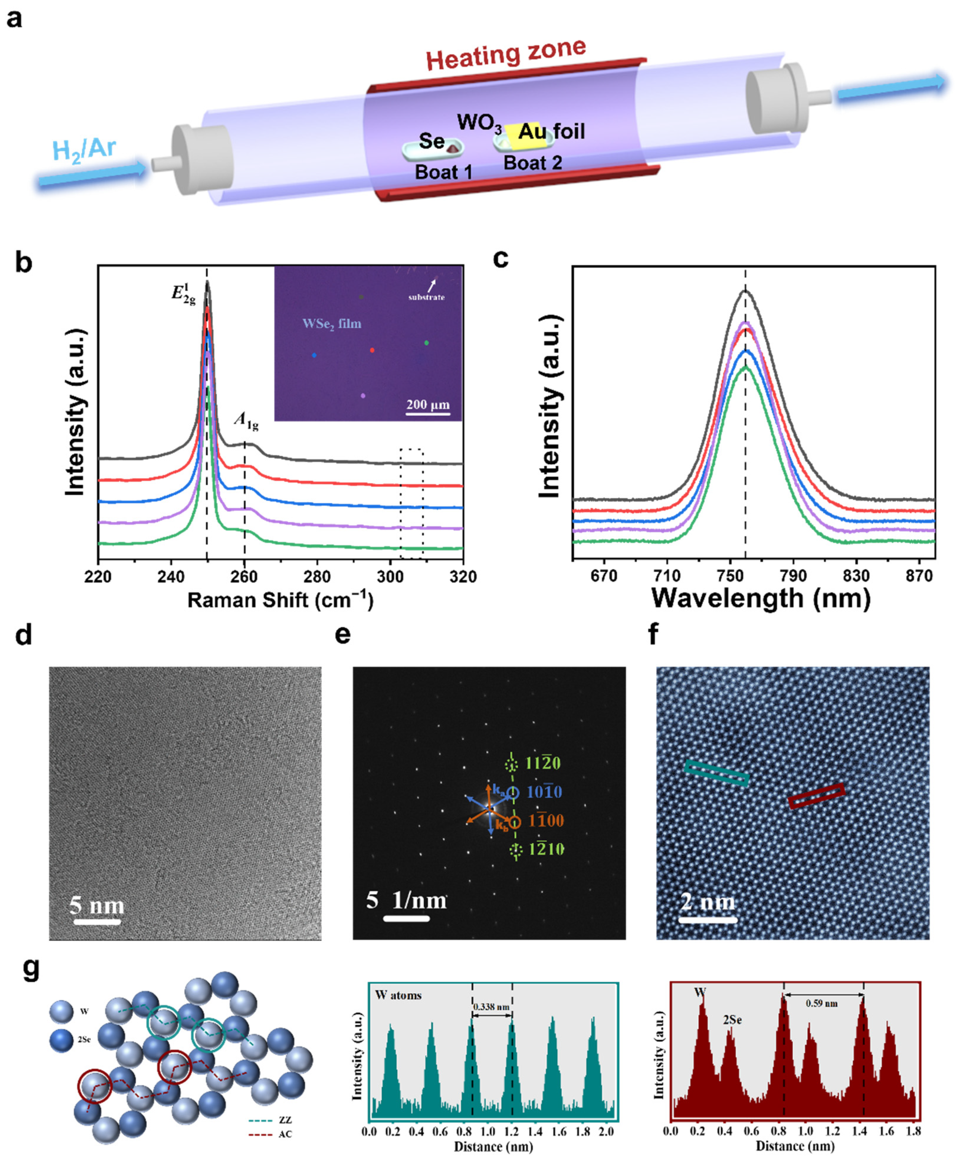
Figure 1. (a) Schematics of the CVD setup for the growth of monolayer WSe2 film on the polycrystalline Au foil. Raman spectra (b) and PL spectra (c) were collected from five random points of the WSe2 sample marked in the insert pictures. (d) Low-magnification TEM image of the WSe2 film. (e) Typical SAED pattern of the sample in (d). (f) The colored STEM image of monolayer WSe2 film. (g) Atomic structure mode of monolayer WSe2 film. Corresponding intensity profiles along the zigzag direction (green) and the armchair direction (red) are labelled in (f), respectively.
Nanomaterials 13 01368 g001
Figure 2. (a) Schematic illustration of the transfer-free fabrication process of monolayer WSe2 FETs. (b) HRTEM cross-sectional images of an as-grown WSe2 on the Au foil, with element distribution pictures. Scale bar is 10 nm.
Nanomaterials 13 01368 g002
Figure 3. Electrical characteristics of the back-gate WSe2 FETs with transfer-free method and conventional thermal deposition method. (a) Ids-Vds output curves and (b) Ids-Vgs transfer curves of monolayer WSe2 FETs using transfer-free method. (c) Ids-Vds output curves of transfer-free devices measured between adjacent Au electrodes. (d) Ids-Vds output characteristics of transfer-free devices measured within several weeks. (e) Ids-Vds output curves and (f) Ids-Vgs transfer curves of monolayer WSe2 FETs with Au electrodes thermally deposited.
Nanomaterials 13 01368 g003
Figure 4. (a) Transfer characteristics of transfer-free monolayer WSe2-based photodetectors under different 532 nm laser power densities. (b) Ids-Vds output curves under different light illuminations. (Insert shows the device photocurrent as a function of P). (c) Dependence of the responsivity on the power density with different values of back-gate voltage. (d) Time-dependent dynamic photoresponse at different bias voltage under 532 nm incident light illumination with a power intensity of 3.05 mW/cm2.
Nanomaterials 13 01368 g004
Disclaimer/Publisher’s Note: The statements, opinions and data contained in all publications are solely those of the individual author(s) and contributor(s) and not of MDPI and/or the editor(s). MDPI and/or the editor(s) disclaim responsibility for any injury to people or property resulting from any ideas, methods, instructions or products referred to in the content.