Article

High-Efficiency Chemical-Mechanical Magnetorheological Finishing for Ultra-Smooth Single-Crystal Silicon

1
Laboratory of Science and Technology on Integrated Logistics Support, National University of Defense Technology, Changsha 410073, China
2
College of Intelligence Science and Technology, National University of Defense Technology, Changsha 410073, China
3
National Innovation Institute of Defense Technology, Academy of Military Sciences, Beijing 100091, China
*
Author to whom correspondence should be addressed.
Nanomaterials 2023, 13(3), 398; https://doi.org/10.3390/nano13030398
Submission received: 11 December 2022 / Revised: 14 January 2023 / Accepted: 16 January 2023 / Published: 18 January 2023
(This article belongs to the Section Nanofabrication and Nanomanufacturing)

Abstract

:
To improve the material removal efficiency and surface quality of single-crystal silicon after magnetorheological finishing, a novel green chemical-mechanical magnetorheological finishing (CMMRF) fluid was developed. The main components of the CMMRF fluid are nano-Fe3O4, H2O2, CH3COOH, nanodiamond, carbonyl iron powder, and deionized water. The novel CMMRF fluid can simultaneously achieve Ra 0.32 nm (0.47 mm × 0.35 mm measurement area), Ra 0.22 nm (5 μm × 5 μm measurement area), and 1.91 × 10⁻² mm3/min material removal efficiency. Comprehensive studies utilizing a scanning electron microscope and a magnetic rheometer show that the CMMRF fluid has a high mechanical removal effect due to the well-dispersed nanodiamond and nano-Fe3O4 particles. The results of Fourier transform infrared spectra and Young’s modulus test reveal the mechanism of the chemical reaction and the mechanical characteristics deterioration of the modified layer. Under co-enhanced chemical and mechanical effects, an ultra-smooth and highly efficient MRF technology for single-crystal silicon is realized.

1. Introduction

An X-ray reflector is the essential part of the synchrotron radiation source [1,2,3]. Its manufacturing precision and surface quality have a decisive effect on the focusing of the X-ray beam [4,5,6]. X-ray reflectors are typically designed as complicated, curved surfaces. Due to the grazing incidence features of X-ray, the reflectors utilized in synchrotron radiation sources are often elongated, and their length in the direction of X-ray incidence can reach hundreds of millimeters, or even longer [7,8,9].
The preferred substrate material for X-ray reflectors is single-crystal silicon, which has exceptional thermal characteristics, mechanical properties, and processability.
Magnetorheological finishing (MRF) is a deterministic sub-aperture polishing technique based on a magnetically sensitive fluid that removes material via a shearing mechanism with minimal normal load [10,11]. Driven by a five-axis motion system, the MRF tool can improve surface quality [12,13], remove subsurface damage [14,15], and eliminate residual stress [16] when correcting surface form errors. Therefore, the MRF is frequently employed in the fine correction stages of the X-ray reflector manufacturing process [17,18].
X-ray reflectors require the roughness of the single-crystal silicon substrate to be Ra 0.3 nm or lower. Current MRF technology is still far from achieving this level, so an additional ultra-smooth process needs to be introduced to improve the surface quality after MRF [19]. In addition, the single-crystal silicon substrate after grinding may have form error ranging from submicron to several microns [20], making the polishing and surface correction cycle quite lengthy [21]. Improving the removal efficiency and the ability to process ultra-smooth surfaces of MRF is of significant benefit to the manufacture of X-ray reflectors, as well as large-aperture high-power laser optical components and ultra-large-aperture astronomical telescopes [22,23].
Numerous significant efforts have been devoted to enhancing the efficiency or surface quality of MRF. In terms of improving the efficiency of MRF, QED novel developments have been made with the fluid nozzle, magnetic field, and wheel geometry and wheel size to increase the removal rate. Custom nozzle shapes are used to create a very wide MRF ribbon resulting in a much wider removal function spot [24]. The polishing wheel with a 500 mm diameter has resulted in a significant increase in polishing speed and removal efficiency [25]. Ren substituted a belt for the large-diameter polishing wheel, which reduced the overall size of the device and increased the polishing contact area [26]. Jung sintered carbon nanotubes and iron powder as a new form of abrasive, which not only improved the durability of the abrasive, but also improved the material removal efficiency of MRF [27]. Jang incorporated the electrochemical corrosion effect into MRF for conducting hard materials; the formed oxide layer has 20% less hardness than the substrate, effectively enhancing the efficiency of MRF [28]. In terms of the ultra-smooth MRF process, Wang discovered that dual-rotor movement randomizes the material removal of MRF, prevents the formation of directional grooves on the surface, and considerably improves the surface roughness [29]. Zhang optimized the formulation of the MRF fluid and employed nanodiamonds as the abrasive for single-crystal silicon polishing, avoiding the comet tail phenomenon and the surface roughness of the aspheric single-crystal silicon after MRF achieved Ra 1.2 nm [30]. QED has reported a novel MRF fluid that can process an ultra-smooth surface of Ra 0.2 nm on glass-ceramics [31]. Sidpara developed a surface roughness prediction model based on the ratio of MRF fluid and process parameters, and optimized the process parameters to reduce the surface roughness of single-crystal silicon from Ra 1300 nm to Ra 8 nm [32]. Most studies do not simultaneously improve efficiency and surface quality. To address this challenge, it is preferable to modify the surface with external energy (chemical energy, light energy, or electric energy) and then remove the modified layer through mechanical action.
Chemical-mechanical polishing (CMP) is a process in which the material is removed by a chemical-mechanical synergetic mechanism, and it is regarded as the most effective method for achieving the sub-nano surface roughness [33,34]. Inspired by CMP technology, an eco-friendly chemical-mechanical magnetorheological finishing (CMMRF) fluid was developed. This fluid will be compatible with the principles of green and sustainable development and will not harm the environment or the operators.
With the advancement of the semiconductor industry, the CMP technology of single-crystal silicon has reached a highly developed state. In an alkaline environment, the nano-SiO2 abrasive can react with the surface of single-crystal silicon to generate a soft layer, which is then removed by the abrasive to reveal a smooth substrate [35]. However, compared with the wafer planarization process, the minimal normal load and the small polishing contact area of MRF cause the efficiency of MRF fluid configured with nano-SiO2 is quite low. To achieve a high-efficiency and ultra-smooth CMMRF process for single-crystal silicon, it is important to find alternative chemical additives and abrasives.
The objective of this study is to configure a novel eco-friendly CMMRF fluid to achieve efficient ultra-smooth processing of single-crystal silicon. The CMMRF fluid is composed of nanodiamond abrasives, carbonyl iron powder (CIP), nano-Fe3O4, H2O2, CH3COOH, and deionized water. The novel polishing fluid can achieve a volume removal rate of 1.91 × 10⁻² mm3/min and a surface roughness of Ra 0.22 nm (5 μm × 5 μm). The roughness is reduced by 51.2% and the efficiency has grown by 196.9% in comparison to the pure nanodiamond MRF fluid. These results demonstrate that the CMMRF fluid has an excellent performance in the high-efficiency process of ultra-smooth single-crystal silicon. In order to optimize and clarify the mechanism of the novel CMMRF fluid, a series of characterization experiments were carried out. The magnetic rheometer results demonstrate that nano-Fe3O4 increases the shear yield strength of MRF fluid, and the nanodiamond abrasives with the sharp cutting-edge lead to such a high material removal rate. A heterogeneous Fenton reagent composed of H2O2, nano-Fe3O4, and CH3COOH was characterized and optimized by spectrophotometer. The heterogeneous Fenton reagents generates a large number of hydroxyl radicals(·OH) which oxidize the surface and generate a silicon dioxide modified layer. The Young’s modulus test and Fourier transform infrared (FTIR) spectra indicate that the hydroxyl group in the solution can enhance the hydrolysis reaction of the modified layer, destroy its network structure, and degrade its mechanical properties. Compared to the mechanical MRF fluid, the novel CMMRF fluid considerably improves chemical and mechanical effects, enabling a high-efficiency ultra-smooth single-crystal silicon process.

2. Samples Preparation and Characterizations

The materials used to configure the MRF fluid in this paper include CIP with an average particle size of 2 μm, Fe3O4 with an average particle size of 20 nm, diamond polishing particles with an average particle size of 150 nm, deionized water, CH3COOH, PEG200, HCl, and NaOH. The details of different constituents used for the MRF are mentioned in Table 1.
Single-crystal silicon CZ-(111), with a diameter of 100 mm and a thickness of 10 mm, was utilized as the experiment sample for roughness and material removal efficiency. The initial surface roughness was approximately Ra 1 nm after fully pitched polishing, and the form error PV was less than 1 μm. As shown in Figure 1, the self-developed MRF machine tool (KDUPF650-7, NUDT, Changsha, China) was utilized to process the single-crystal silicon. The electromagnet was installed inside the polishing wheel, and the intensity of the magnetic field was controlled by adjusting the current of the electromagnet coil. The polishing wheel has a diameter of 200 mm and is driven by a motor. The magnetorheological fluid is stored in the storage tank, flows out from the nozzle through the centrifugal pump, and is recovered to realize the circulation. The process parameters are as follows: the magnetic field current is 8A; the polishing wheel speed is 180 rpm; the flow rate is 200 L/h; and the ribbon penetration depth is 0.3 mm. The surface roughness results are obtained by MRF uniformly polishing. The uniform polishing path is a raster path with a step of 1 mm, and the feed rate of the MRF tool is 100 mm/min. The uniform polishing runs once on each sample. The MRF tool influence function (TIF) was obtained from the fixed-point experiment, and the volume removal rate (VRR) was calculated according to the TIF.
The sample roughness results were measured by an atomic force microscope (AFM, Dimension icon, Bruker, Billerica, MA, USA) and a white light interferometer (WLI, New view 7000, Zygo, Middleboro, MA, USA). The measuring area of the AFM is 5 μm × 5 μm, and the tapping mode was used for surface microscopic topography imaging. The WLI has a magnification of 20 times, and the field of view is 0.47 mm × 0.35 mm.
The content of ·OH in CMMRF fluid determines the oxidation effect of single-crystal silicon. Spectrophotometry was used to measure the content of ·OH in the CMMRF fluid. 2,3-dihydroxybenzoic acid and 2,5-dihydroxybenzoic acid produced by the reaction of salicylic acid with ·OH will have strong absorption peaks at 510 nm. We prepared a mixed solution of salicylic acid, ethanol, and deionized water as a catcher for ·OH, in which the concentration of salicylic acid was 1.8 mol/L, and the ratio of ethanol to water was 1:3. A UV-VIS-NIR 3600(Shimadzu, Kyoto, Japan) spectrophotometer was used to measure the absorbance of mixed solutions containing different formulas of CMMRF fluid and catcher.
MRF base fluid refers to the combination of the liquid components in the MRF fluid. In the CMMRF base fluid environment, the dispersion condition of diamond abrasive and CIP with nano-Fe3O4 was photographed using a scanning electron microscope (SEM, MIRA3 AMU, TESCAN, Brno, Czech Republic). The shear yield strength of the MRF fluid was measured by Anton Paar MCR302 rheometer with an MRD180 module.
To characterize the chemical-mechanical mechanism of CMMRF fluid on single-crystal silicon, Young’s modulus and FTIR tests were conducted on single-crystal silicon CZ- (111) samples with a diameter of 10 mm and a thickness of 3 mm. After fully pitched polishing, the samples’ surface roughness was approximately Ra 1 nm. Using a plasma processing system (Ion wave 10), we conducted 1000 W power Ar gas plasma cleaning for 60 s to eliminate organic pollution from the sample surface. Then, the original oxide layer on the sample surface was removed by soaking it in buffered oxide etch (BOE) solution for 3 min. In the BOE solution, the volume ratio of HF, NH4F, and deionized water was 1:10:50. The samples were immediately cleaned in a 270 kHz ultrasonic cleaner with deionized water for 5 min after the oxide layer had been removed. Transfer samples from which the oxide layer had been removed, was added to various CMMRF solutions and soaked for 24 h at 26 °C. We then took out the samples and cleaned them for 5 min in a 270 kHz ultrasonic cleaner with deionized water. The Young’s modulus of the modified layer was measured with a Bruker Dimension Icon AFM equipped with a PeakForce QNM module, and the probe model used for the measurement was DNISP-HS. The measurement area was 5 μm × 5 μm, and the average of the three measurements was regarded as the Young’s modulus of the modified layer. FTIR (Nicolet iS20, Thermo Scientific, Waltham, MA, USA) was employed to detect the chemical composition of the modified layer.

3. Results and Discussion

The design idea of the CMMRF fluid is based on the uniform wet etching technique for single-crystal silicon. First, a powerful oxidant is chosen to uniformly oxidize the surface, followed by the removal of the oxide layer to obtain an ultra-smooth surface.
The Fenton reagent contains a large amount of ·OH, and the oxidation potential of ·OH has reached 2.80 V, which is suitable for oxidizing the single-crystal silicon. Meanwhile, the concentration of Fe3+ or Fe2+ in the homogenous Fenton reagent is too high for direct discharge without treatment.
In the heterogeneous Fenton reagent, H2O2 reacts on the surface of the solid catalyst to generate ·OH, and the chemical reaction is as follows [36]:
F e 3 + + H 2 O 2 F e 2 + + H O 2 · + H +
F e 2 + + H 2 O 2 F e 3 + + · O H + O H
where the ≡Fe2+ and ≡Fe3+ represent the iron ions on the solid catalyst surface, and Fe2+ and Fe3+ represent the iron ions in the solution. In an acidic environment, redox cycles occur on the catalyst surface and in the liquid. Ferrihydrite [37], goethite [38], and Fe3O4 [39] are frequently utilized in heterogeneous Fenton reagents. These catalysts may be separated and reused through magnetic suction or sedimentation filtering, effectively preventing environmental contamination. Nano-Fe3O4 has exceptional catalytic and magnetic properties, and is widely utilized in MRF fluid and heterogeneous Fenton reagent. In this article, nano-Fe3O4 is used to develop a novel CMMRF fluid.
There are three factors affecting the oxidation effect of heterogeneous Fenton reagent, namely, pH value, concentration of H2O2, and concentration of the catalyst [40]. The concentration of ≡Fe2+ and ≡Fe3+ on the surface of the catalyst is the primary reason why pH influences oxidation activity. As the pH increases, the metal ions will precipitate, the oxidation potential of ·OH will decrease at the same time, and H2O2 is easily degraded into oxygen and water, which influences the generation of ·OH. For the concentration of H2O2, when H2O2 is inadequate, the amount of generated ·OH will be insufficient, whereas an excess of H2O2 will lead to the annihilation of ·OH.
Within a certain concentration range, the active site increases with the concentration of the catalyst, but excessive catalyst will consume the generated ·OH. The reaction is shown in the following equation:
F e 2 + + · O H F e 3 + + O H
To optimize these three factors, the absorbance of the mixture of CMMRF fluid and ·OH catcher was measured.
As pH regulators, CH3COOH and NaOH are utilized, and the range of pH is between 2.5 and 9. As shown in the Figure 2, the reagent absorbance and the pH value have an obvious negative correlation. When the pH is greater than 6, the absorbance of the reagent is close to 0, which shows that the reagent contains almost no ·OH.
CH3COOH cannot be totally ionized since it is a monobasic weak acid. When pH = 2.5, the concentration of CH3COOH is 0.5 mol/L (1.5% vol), and when pH = 3 it is 0.05 mol/L (0.15% vol). The absorbance of the reagent is only 3.5 higher at pH = 2.5 than at pH = 3. Therefore, the pH of CMMRF fluid is set to 3, which saves CH3COOH, prevents the corrosion of processing equipment caused by high CH3COOH concentrations, and ensures the oxidation effect of CMMRF fluid.
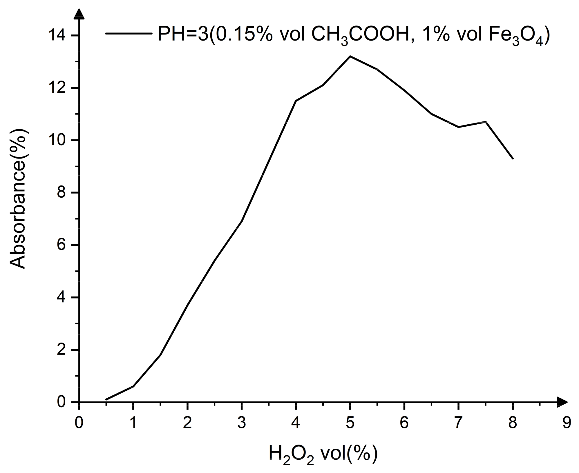
The effect of H2O2 concentration on absorbance is shown in Figure 3. As the concentration of H2O2 rises, the absorbance of the reagent progressively increases, reaching a peak value at 5% vol H2O2, and then decreases as the concentration of H2O2 continues to rise.
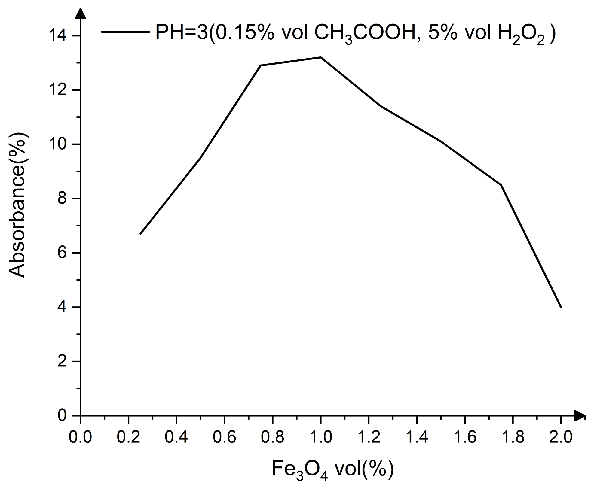
The effect of Fe3O4 on absorbance follows the same pattern as that of H2O2, with an initial increase followed by a decline. Figure 4 shows that when the volume of Fe3O4 is 1%, the reagent produces the maximum concentration of ·OH.
The optimized CMMRF fluid composition is deionized water 60% vol, H2O2 5% vol, CH3COOH 0.15% vol, CIP 25% vol, nano-Fe3O4 1% vol, nanodiamond abrasive 3% vol, and PEG200 5.85% vol. Nanodiamond abrasive consists of carbon atoms, and possesses ultra-high hardness and stable chemical characteristics at room temperature. H2O2 is frequently used for disinfection and sterilization at low concentrations. CH3COOH is an organic acid that is the primary component of vinegar. A suitable amount of CIP can be used as a dietary additive to supplement the needs of the human body. PEG200 is polyethylene glycol with an average molecular weight of 200. It is a green organic solvent that can distribute particles in CMMRF fluid and adjust its viscosity. It is evident that the components of the CMMRF fluid are harmless to the environment and operators.
As a comparison of CMMRF fluid, the MRF fluid with pure mechanical material removal is configured as follows: deionized water 65% vol, CIP25% vol, nanodiamond 3%, PEG200 7% vol, and pH adjusted to 3 with HCl, which is consistent with the CMMRF fluid. Comparing the performance of these two kinds of fluid, Figure 5 shows the results of surface roughness Ra and VRR after different MRF fluid processing. From the surface roughness results measured by WLI and AFM, it can be seen that the surface texture after CMMRF is more uniform and the surface quality after CMMRF is also significantly improved. Furthermore, the VRR of the novel CMMRF fluid is 1.91 × 10⁻² mm3/min, which increases by 196.9% compared with 0.97 × 10⁻² mm3/min obtained by the mechanical MRF fluid. The peak removal rate (PRR) of CMMRF is 1.32 μm/min, which is 186.6% greater than the PRR of the mechanical MRF fluid (0.71 μm/min). Therefore, it is demonstrated that the novel green CMMRF fluid has superior performances when polishing single-crystal silicon.
To characterize the performance of the CMMRF fluid, the nanodiamond abrasive and CIP mixed with nano-Fe3O4 were photographed by a SEM in the CMMRF base fluid environment. It can be seen in Figure 6a that the nanodiamond has a good dispersion and homogeneous particle size, which is beneficial to the processing of a high-quality surface. The shape of the nanodiamond is an irregular polygon, and each side of the polygon can be regarded as a sharp micro-cutting edge, which is helpful to improve the material removal efficiency. In Figure 6b, it can be seen that both CIP and nano-Fe3O4 are spherical, and the regular spherical shape is beneficial for preventing surface defects during processing.
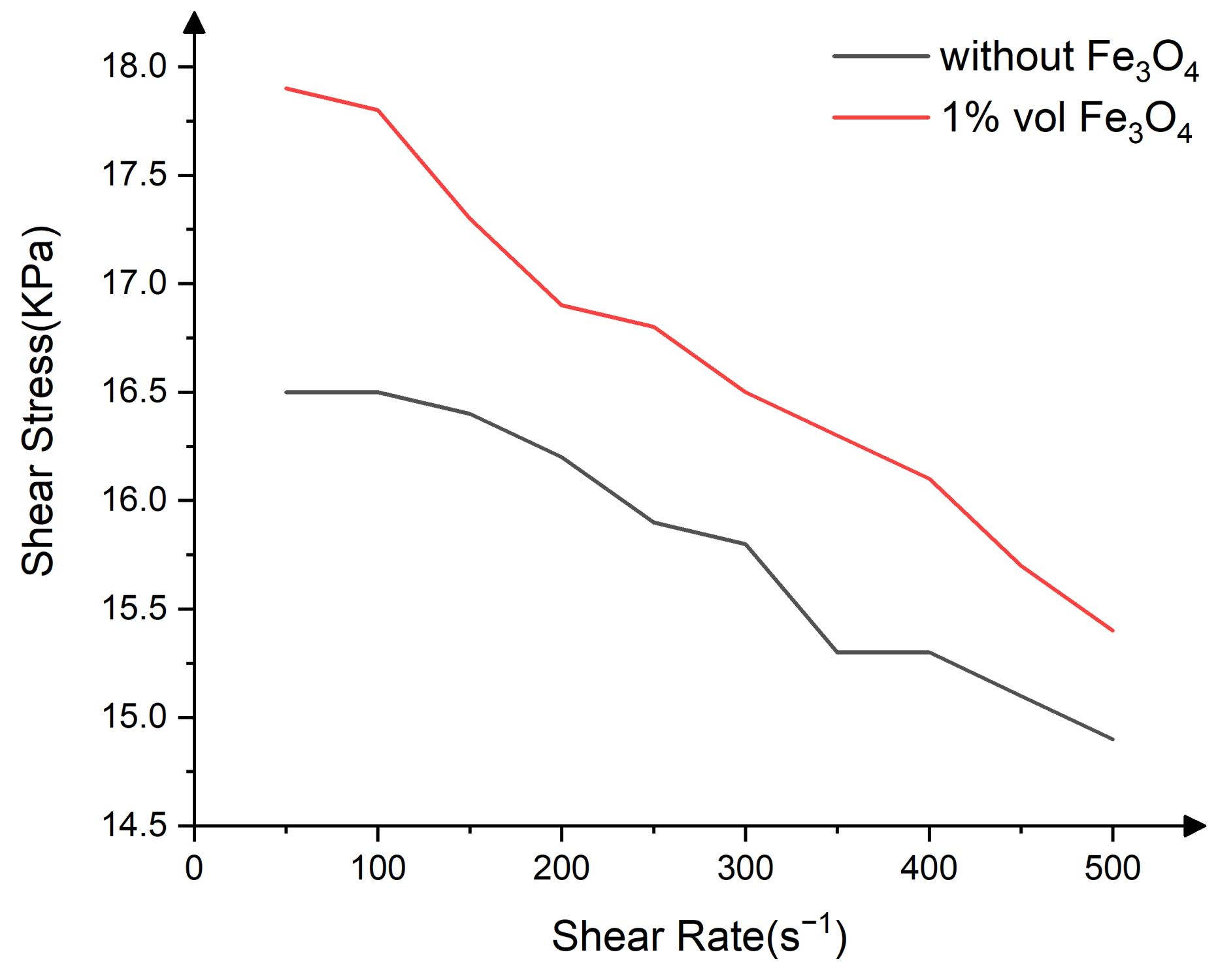
Figure 7 shows the test results of the magnetic rheometer. The shear yield strength of MRF fluid increased by 5.7% at 250 s−1 when nano-Fe3O4 was added. Under the influence of an external directional magnetic field, the CIPs are arranged in a chain structure, and nano-Fe3O4 is embedded in the gap between the CIP and enhances the magnetic dipole–dipole force, which is reflected as an increase of shear yield strength. With an increase in shear yield strength, the capacity of MRF fluid to hold nanodiamond polishing particles is enhanced, which is beneficial for improving the removal efficiency of materials.
To investigate the reaction mechanism of CMMRF on the single-crystal silicon, various chemical substances were added to configure the different MRF fluids, and three samples with its original oxide layer removed were immersed in it. As shown in Table 2, fluid No. 1 and No. 2 are adjusted to pH = 3 with HCl, while fluid No. 3 is adjusted to pH = 3 using CH3COOH.
Young’s modulus is measured at three points on each sample, with a range of 5 μm × 5 μm at each point. The average of three points is regarded as the Young’s modulus of this sample. The measurement results are shown in Figure 8. The Young’s modulus of single-crystal silicon is 113 GPa [41]. As shown in Figure 8, after 24 h of immersion in MRF fluid, the Young’s modulus of the single-crystal silicon sample decreased to 97.8 GPa, and the Young’s modulus of Sample No. 2 and Sample No. 3 decreased to 89.5 GPa and 81.6 GPa, respectively.
From Figure 9a, it can be seen that each sample has strong peaks at the position of 471 cm−1 (Si-O), 778 cm−1 (Si-O), and 1113 cm−1 (Si-O-Si) [42], which are the characteristic peaks of SiO2, and the absorption peaks of Samples No. 2 and No. 3 are significantly stronger than that of Sample No. 1. In addition, compared with Sample No. 1 and No. 2, Sample No. 3 has a strong absorption band at 973 cm−1 (Si-OH). It can be seen from Figure 9b, at the position of 3417 cm−1 (OH group), the absorption bands of Sample No. 1, Sample No. 2, and Sample No. 3 are intensified sequentially [43].
During the Young’s modulus test, the degradation of the sample mechanical properties will be aggravated by a thicker modified layer. It can be inferred that the thickness of the modified layer of Sample No. 1 is less than that of other samples, and the absorption peak intensity of Sample No. 2 and Sample No. 3 is higher than that of Sample No. 1, confirming this conclusion again. This is because the heterogeneous Fenton reagent composed of nano-Fe3O4 and H2O2 has a better oxidation performance and generates a thicker modified layer within the same treatment time.
The modified layer of Sample No. 3 is attacked by the hydroxyl group in CH3COOH, which destroys the structure of the oxidation product SiO2, resulting in a further decrease in Young’s modulus [44,45,46]. According to the research, the VRR of MRF is proportional to the Young’s modulus; hence, the soft modified layer leads to a significant increase in MRF removal efficiency.
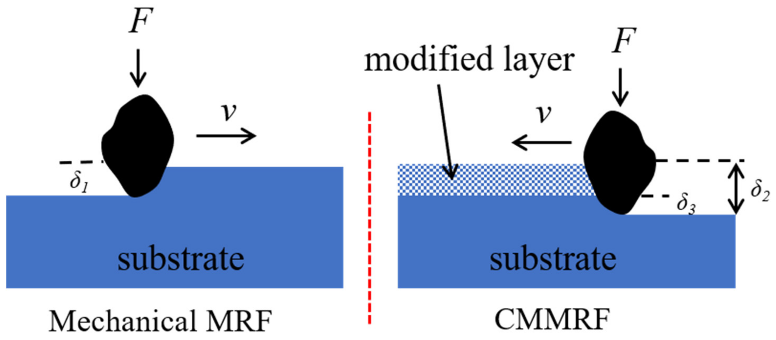
As depicted in Figure 10, the nondiamond abrasive entirely removed the modified layer in the CMMRF process. The presence of the modified layer reduces the substrate penetration depth (δ3) of abrasives, while the total penetration depth (δ2) is greater than that of mechanical MRF (δ1). The microscopic topography formed by abrasives will be more uniform when the substrate penetration depth is lower, and an increase in the total penetration depth will improve the material removal efficiency.
Furthermore, it should be noted that the chemical-mechanical balance and electrostatic force between the abrasive and modified layer also play vital roles in the high-efficiency ultra-smooth process. Further research is needed to fill the gaps in the CMMRF material removal mechanism.

4. Conclusions

In this paper, a novel CMMRF fluid is developed and realizes high-efficiency ultra-smooth processing of single-crystal silicon. The novel fluid is harmless to the environment and the operators, and the solid components in the fluid can be recycled and reused.
The polishing mechanism of CMMRF was revealed by comprehensive characterizations. The nano-Fe3O4 enhanced the shear yield strength of the fluid, and the employment of the hard nanodiamond abrasive was beneficial for improving the material removal efficiency. The heterogeneous Fenton reagent is composed of Fe3O4 and H2O2; the ·OH can rapidly oxidize single-crystal silicon. The addition of CH3COOH considerably enhanced the material removal rate by destroying the modified layer with the hydrolysis reaction. In addition, the modified layer reduces the substrate penetration depth of the abrasives, resulting in a significant improvement in surface roughness. This article could be a reference for the high-efficiency ultra-smooth processing of silicon. After the optimization of processing parameters, it can also be applied to a variety of materials as far as the modified layer can be generated on the surface.

Author Contributions

Conceptualization, Z.L., H.H. and Y.D.; methodology, Z.L.; validation, Z.L., H.H. and S.X.; formal analysis, S.X.; investigation, Y.Z.; resources, Y.Z.; data curation, S.X.; writing—original draft preparation, Z.L.; writing—review and editing, Z.L.; visualization, Z.L. and Y.Z.; supervision, H.H., S.X. and Y.D.; project administration, H.H., S.X. and Y.D.; funding acquisition, H.H., S.X. and Y.D. All authors have read and agreed to the published version of the manuscript.

Funding

The National Natural Science Foundation of China (51835013, 51991371, 52105567).

Data Availability Statement

Data are contained within the article.

Acknowledgments

This research was supported by the National Natural Science Foundation of China.

Conflicts of Interest

The authors declare no conflict of interest.

References

  1. Mimura, H.; Handa, S.; Kimura, T.; Yumoto, H.; Yamakawa, D.; Yokoyama, H.; Matsuyama, S.; Inagaki, K.; Yamamura, K.; Sano, Y. Breaking the 10 nm barrier in hard-X-ray focusing. Nat. Phys. 2010, 6, 122–125. [Google Scholar] [CrossRef] [Green Version]
  2. Fujisawa, T.; Inoue, K.; Oka, T.; Iwamoto, H.; Uruga, T.; Kumasaka, T.; Inoko, Y.; Yagi, N.; Yamamoto, M.; Ueki, T. Small-angle X-ray scattering station at the SPring-8 RIKEN beamline. J. Appl. Crystallogr. 2010, 33, 797–800. [Google Scholar] [CrossRef]
  3. Spiller, E. Soft X-ray Optics. Opt. Photonics. News. 1993, 7, 60. [Google Scholar]
  4. Siewert, F.; Buchheim, J.; Boutet, S.; Williams, G.J.; Signorato, R. Ultra-precise characterization of LCLS hard X-ray focusing mirrors by high resolution slope measuring deflectometry. Opt. Express 2012, 20, 4525–4536. [Google Scholar] [CrossRef] [PubMed] [Green Version]
  5. Pardini, T.; Cocco, D.; Hau-Riege, S.P. Effect of slope errors on the performance of mirrors for X-ray free electron laser applications. Opt. Express 2015, 23, 31889. [Google Scholar] [CrossRef]
  6. Shi, X.; Assoufid, L.; Reininger, R. How to specify super-smooth mirrors: Simulation studies on nano-focusing and wavefront preserving X-ray mirrors for next-generation light sources. In Proceedings of the 8th International Symposium on Advanced Optical Manufacturing and Testing Technology (AOMATT2016), Suzhou, China, 26–29 April 2016. [Google Scholar]
  7. Tatchyn, R.; Arthur, J.; Boyce, R.; Fasso, A.; Howells, M. X-ray optics design studies for the SLAC 1.5-15 Angstrom Linac Coherent Light Source (LCLS). Nucl. Instrum. Methods Phys. Res. 1999, 429, 397–406. [Google Scholar] [CrossRef]
  8. Guigay, J.P.; Morawe, C.; Mocella, V.; Ferrero, C. An analytical approach to estimating aberrations in curved multilayer optics for hard x-rays: 1. Derivation of caustic shapes. Opt. Express 2008, 16, 12050–12059. [Google Scholar] [CrossRef] [PubMed]
  9. Morawe, C.; Guigay, J.P.; Mocella, V.; Ferrero, C. An analytical approach to estimating aberrations in curved multilayer optics for hard X-rays: 2. Interpretation and application to focusing experiments. Opt. Express 2008, 16, 16138–16150. [Google Scholar] [CrossRef] [PubMed]
  10. Jacobs, S.; Golini, D.; Hsu, Y.; Puchebner, B.; Strafford, D.; Prokhorov, I.; Fess, E.; Pietrowski, D.; Kordonski, W. Magnetorheological finishing: A deterministic process for optics manufacturing. In Proceedings of the International Conferences on Optical Fabrication and Testing and Applications of Optical Holography, Tokyo, Japan, 2 August 1995. [Google Scholar]
  11. Kordonski, W.; Gorodkin, S. Material removal in magnetorheological finishing of optics. Appl. Opt. 2011, 50, 1984–1994. [Google Scholar] [CrossRef] [PubMed]
  12. Dumas, P.; McFee, C. Novel MRF fluid for Ultra-Low Roughness optical surfaces. In Proceedings of the 7th International Symposium on Advanced Optical Manufacturing and Testing Technologies: Advanced Optical Manufacturing Technologies (AOMATT 2014), Harbin, China, 6 August 2014. [Google Scholar]
  13. Dumas, P.; Golini, D.; Tricard, M. Improvement of figure and finish of diamond turned surfaces with magneto-rheological finishing (MRF). In Proceedings of the Window and Dome Technologies and Materials IX, Orlando, FL, USA, 18 May 2005. [Google Scholar]
  14. Catrin, R.; Neauport, J.; Taroux, D.; Cormont, P.; Maunier, C.; Lambert, S. Magnetorheological finishing for removing surface and subsurface defects of fused silica optics. Opt. Eng. 2014, 53, 7. [Google Scholar] [CrossRef]
  15. Campbell, J.H.; Hawley-Fedder, R.; Stolz, C.J.; Menapace, J.A.; Borden, M.R. NIF optical materials and fabrication technologies: An overview. In Proceedings of the Optical Engineering at the Lawrence Livermore National Laboratory II: The National Ignition Facility, San Jose, CA, USA, 28 May 2004. [Google Scholar]
  16. Ghosh, G.; Sidpara, A.; Bandyopadhyay, P.P. Experimental and theoretical investigation into surface roughness and residual stress in magnetorheological finishing of OFHC copper. J. Mater. Process. Technol. 2021, 288, 116899. [Google Scholar] [CrossRef]
  17. Thiess, H.; Lasser, H.; Siewert, F. Fabrication of X-ray mirrors for synchrotron applications. Nucl. Instrum. Methods Phys. Res. 2010, 616, 157–161. [Google Scholar] [CrossRef]
  18. Seifert, A. New Products for Synchrotron Application Based On Novel Surface Processing Developments. In Proceedings of the Synchrotron radiation instrumention: 9th International Conference on Synchrotron Radiation Instrumentation, Daegu, Republic of Korea, 28 May–2 June 2006. [Google Scholar]
  19. Liu, S.; Wang, H.; Hou, J.; Zhang, Q.; Chen, X.; Zhong, B.; Zhang, M. Combined processing strategy based on magnetorheological finishing for monocrystalline silicon x-ray mirrors. Appl. Opt. 2022, 61, 5575–5584. [Google Scholar] [CrossRef]
  20. Zhong, Y.; Dai, Y.; Xiao, H.; Shi, F. Experimental study on surface integrity and subsurface damage of fused silica in ultra-precision grinding. Int. J. Adv. Manuf. Technol. 2021, 115, 4021–4033. [Google Scholar] [CrossRef]
  21. Yin, L.; Lin, Z.; Hu, H.; Dai, Y. Rapid polishing process for the X ray reflector. Appl. Opt. 2022, 61, 7991–7998. [Google Scholar] [CrossRef] [PubMed]
  22. Burge, J.H.; Kim, D.W.; Martin, H.M. Process optimization for polishing large aspheric mirrors. In Proceedings of the Advances in Optical and Mechanical Technologies for Telescopes and Instrumentation, Montréal, QC, Canada, 28 July 2014. [Google Scholar]
  23. Menapace, J.A. Developing magnetorheological finishing (MRF) technology for the manufacture of large-aperture optics in megajoule class laser systems. In Proceedings of the Laser Damage Symposium XLII: Annual Symposium on Optical Materials for High Power Lasers, Boulder, CO, USA, 3 December 2010. [Google Scholar]
  24. Messner, W.J.; Hall, C. High removal rate MRF[TM]. In Proceedings of the Optifab, Rochester, NY, USA, 28 October 2021. [Google Scholar]
  25. Johnson, J.S.; Grobsky, K.; Bray, D.J. Rapid fabrication of lightweight silicon carbide mirrors. In Proceedings of the International Symposium on Optical Science and Technology, Seattle, WA, USA, 9 September 2002. [Google Scholar]
  26. Kai, R.; Xiao, L.; Li, G.Z.; Yang, B.; Long, X.L. Belt-MRF for large aperture mirrors. Opt. Express 2014, 22, 19262–19276. [Google Scholar]
  27. Jung, B.; Jang, K.I.; Min, B.K.; Sang, J.L.; Seok, J. Magnetorheological finishing process for hard materials using sintered iron-CNT compound abrasives. Int. J. Mach. Tools Manuf. 2009, 49, 407–418. [Google Scholar] [CrossRef]
  28. Kyung, I.; Jang, E.N.; Chan, Y.L.; Jong, W. Mechanism of synergetic material removal by electrochemomechanical magnetorheological polishing. Int. J. Mach. Tools Manuf. 2013, 70, 88–92. [Google Scholar]
  29. Wang, Y.; Zhang, Y.; Feng, Z. Analyzing and improving surface texture by dual-rotation magnetorheological finishing. Appl. Surf. Sci. 2016, 360, 224–233. [Google Scholar] [CrossRef]
  30. Zhang, Y.; Fang, F.; Fan, W.; Huang, W.; He, J. Research on magnetorheological finishing of aspheric optics for single-crystal silicon. In Proceedings of the Second Symposium on Novel Technology of X-ray Imaging, Hefei, China, 10 May 2019. [Google Scholar]
  31. Bentley, J.L.; Stoebenau, S.; Maloney, C.; Oswald, E.S.; Dumas, P. Fine figure correction and other applications using novel MRF fluid designed for ultra-low roughness. In Proceedings of the Optifab, Rochester, NY, USA, 11 October 2015. [Google Scholar]
  32. Sidpara, A.; Jain, V.K. Nano–level finishing of single crystal silicon blank using magnetorheological finishing process. Tribol. Int. 2012, 47, 159–166. [Google Scholar] [CrossRef]
  33. Estragnat, E.; Tang, G.; Liang, H.; Jahanmir, S.; Pei, P.; Martin, J.M. Experimental investigation on mechanisms of silicon chemical mechanical polishing. J. Electron. Mater. 2004, 33, 334–339. [Google Scholar] [CrossRef]
  34. Wang, Y.G.; Zhang, L.C.; Biddut, A. Chemical effect on the material removal rate in the CMP of silicon wafers. Wear 2011, 270, 312–316. [Google Scholar] [CrossRef]
  35. Su, J.X.; Guo, D.M.; Kang, R.K.; Jin, Z.J.; Li, X.J.; Tian, Y.B. Modeling and Analyzing on Nonuniformity of Material Removal in Chemical Mechanical Polishing of Silicon Wafer. Mater. Sci. Forum. 2004, 471–472, 26–31. [Google Scholar] [CrossRef]
  36. Hartmann, M.; Kullmann, S.; Keller, H. Wastewater Treatment with Heterogeneous Fenton-type Catalysts Based on Porous Materials. J. Mater. Chem. 2010, 20, 9002–9017. [Google Scholar] [CrossRef]
  37. Georges, O.N.; Guillaume, M.; Yuheng, W.; Andrea, L.; Foster, F. XANES Evidence for Rapid Arsenic(III) Oxidation at Magnetite and Ferrihydrite Surfaces by Dissolved O2 via Fe2+-Mediated Reactions. Environ. Sci. Technol. 2010, 44, 5416–5422. [Google Scholar]
  38. Chen, L.; Wang, Y.; Zhang, H.; Gao, Y. Goethite as an efficient heterogeneous Fenton catalyst for the degradation of methyl orange. Catal. Today 2015, 252, 107–112. [Google Scholar]
  39. Huang, R.; Fang, Z.; Yan, X.; Wen, C. Heterogeneous sono-Fenton catalytic degradation of bisphenol A by Fe3O4 magnetic nanoparticles under neutral condition. Chem. Eng. J. 2012, 197, 242–249. [Google Scholar] [CrossRef]
  40. Chen, C.H.; Xie, B.; Ren, Y. The mechanisms of affecting factors in treating wastewater by Fenton reagent. J. Environ. Sci. 2000, 21, 93–96. [Google Scholar]
  41. Wakaki, M.; Shibuya, T.; Kudo, K. Physical Properties and Data of Optical Materials, 1st ed.; CRC Press: Boca Raton, FL, USA, 2007; pp. 339–378. [Google Scholar]
  42. Lucovsky, G.; Mantini, M.J.; Srivastava, J.K.; Irene, E.A. Low-temperature growth of silicon dioxide films: A study of chemical bonding by ellipsometry and infrared spectroscopy. J. Vac. Sci. Technol. B 1987, 5, 530–537. [Google Scholar] [CrossRef]
  43. Kim, J.T.; Kim, M.C. Silicon wafer technique for infrared spectra of silica and solid samples (I). Korean J. Chem. Eng. 1986, 3, 45–51. [Google Scholar] [CrossRef]
  44. Cook, L.M. Chemical processes in glass polishing. J. Non. Cryst. Solids 1990, 120, 152–171. [Google Scholar] [CrossRef]
  45. MichalskeI, T.A.; Freiman, S.W. A Molecular Mechanism for Stress Corrosion in Vitreous Silica. J. Am. Ceram. Soc. 1983, 66, 284–288. [Google Scholar] [CrossRef]
  46. Zhang, S.; Liu, Y. The molecular level dissolution mechanisms of quartz under different pH conditions. Geochimica 2009, 38, 549–557. [Google Scholar]
Figure 1. The self-developed MRF machine tool.
Nanomaterials 13 00398 g001
Figure 2. Effect of pH on absorbance.
Nanomaterials 13 00398 g002
Figure 3. Effect of H2O2 concentration on absorbance.
Nanomaterials 13 00398 g003
Figure 4. Effect of Fe3O4 concentration on absorbance.
Nanomaterials 13 00398 g004
Figure 5. Polishing results of different MRF fluid:(a) Surface roughness after mechanical MRF process (measured by WLI); (b) surface roughness after CMMRF process (measured by WLI); (c) surface roughness after mechanical MRF process (measured by AFM); (d) surface roughness after CMMRF process (measured by AFM); (e) comparison of material removal rate of mechanical MRF and CMMRF.
Nanomaterials 13 00398 g005
Figure 6. (a) SEM image of nanodiamond abrasive; (b) CIP mixed with nano-Fe3O4.
Nanomaterials 13 00398 g006
Figure 7. The magnetic rheometer test results of different MRF fluid.
Nanomaterials 13 00398 g007
Figure 8. Young’s modulus test results: The Young’s modulus image of sample (a) No. 1; (b) No. 2; (c) No. 3; (d) average values of Young’s modulus of different samples.
Nanomaterials 13 00398 g008
Figure 9. FTIR spectra of different samples: (a) 400–1800 cm−1; (b) 3000–4000 cm−1.
Nanomaterials 13 00398 g009
Figure 10. Abrasive contact model of mechanical MRF and CMMRF.
Nanomaterials 13 00398 g010
Table 1. Constituents used for configuring MRF fluid.
ConstituentsPuritySupplier
CIP-BASF, Ludwigshafen, Germany
Nano-Fe3O4-Delta, Xiamen, China
Diamond abrasive-Huanghe Whirlwind, Zhengzhou, China
H2O2ARSinopharm Chemical Reagent, Shanghai, China
CH3COOHARSinopharm Chemical Reagent, Shanghai, China
PEG200AROKA, Beijing, China
HClARSinopharm Chemical Reagent, Shanghai, China
NaOHARSinopharm Chemical Reagent, Shanghai, China
Table 2. Components of different fluid.
NumberH2O2 (vol%)Fe3O4 (vol%)CH3COOH (vol%)pH
15--3
251-3
3510.153
Disclaimer/Publisher’s Note: The statements, opinions and data contained in all publications are solely those of the individual author(s) and contributor(s) and not of MDPI and/or the editor(s). MDPI and/or the editor(s) disclaim responsibility for any injury to people or property resulting from any ideas, methods, instructions or products referred to in the content.