
The Manufacturing Conditions for the Direct and Reproducible Formation of Electrospun PCL/Gelatine 3D Structures for Tissue Regeneration


Abstract
:1. Introduction
2. Materials and Methods
2.1. Materials
2.2. Method: Electrospinning Solution Preparation and Instrumentation
2.3. Method: Taguchi Design of Experiments
2.4. Method: Nanofibre and Sponge Characterisation
2.5. Method: Cytocompatibility Study
3. Experimental Results
3.1. The Manufacturing Conditions for PCL Sponge Formation

| Humidity (%) | Temperature (°C) | Run No. | Distance (cm) | Voltage (kV) | Rate (µL/h) | w/v% | Sponge Quality Score | Fibre Diameter (µm) |
|---|---|---|---|---|---|---|---|---|
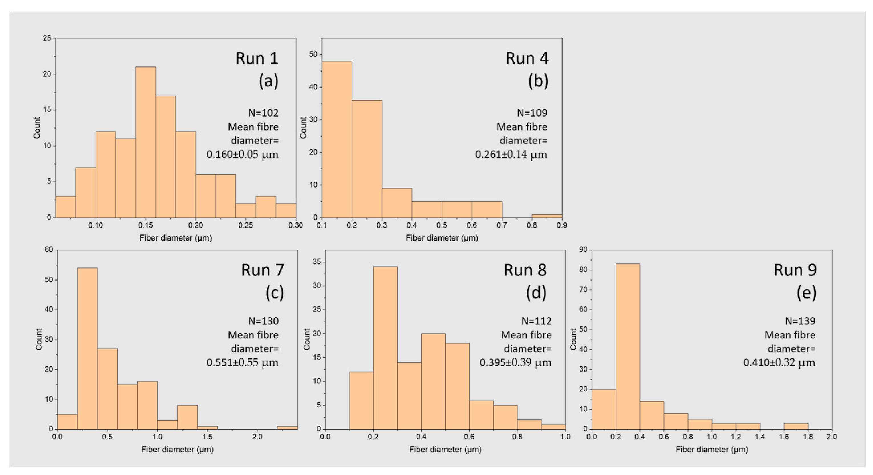
| 43 | 23 | 1 | 10 | 12 | 500 | 14 | 2 | 0.160 ± 0.005 |
| 2 | 15 | 16 | 1250 | 14 | 1 | N/A | ||
| 3 | 20 | 20 | 2000 | 14 | 1 | N/A | ||
| 36 | 24 | 4 | 15 | 20 | 500 | 18 | 4 | 0.260 ± 0.015 |
| 5 | 20 | 12 | 1250 | 18 | 1 | N/A | ||
| 6 | 10 | 16 | 2000 | 18 | 1 | N/A | ||
| 38 | 24 | 7 | 20 | 16 | 500 | 22 | 4 | 0.550 ± 0.030 |
| 8 | 10 | 20 | 1250 | 22 | 4 | 0.400 ± 0.020 | ||
| 9 | 15 | 12 | 2000 | 22 | 3 | 0.410 ± 0.030 |
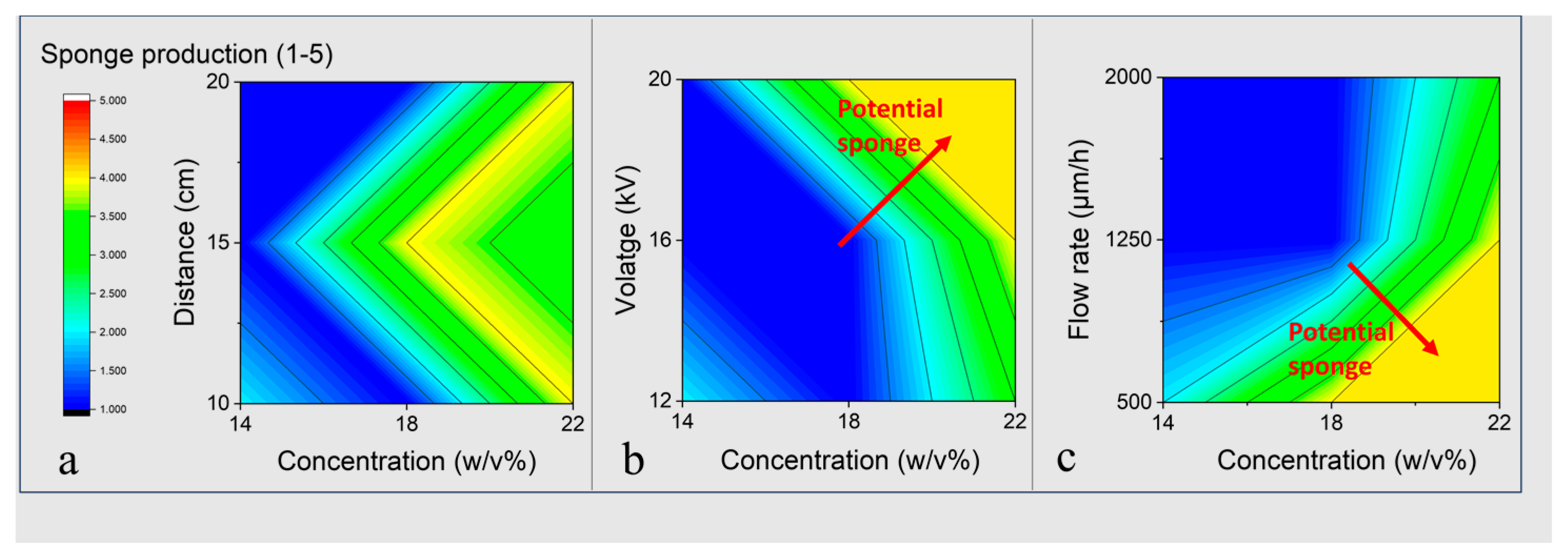
3.2. Preparation Parameters Effect on the Physical-Chemical Characteristics of PCL Sponge
3.3. The Manufacturing Conditions for PCL/Gel Sponge Formation-Increasing Conductivity
3.4. PCL/Gelatine Sponge Characterisation—Fibre Morphology
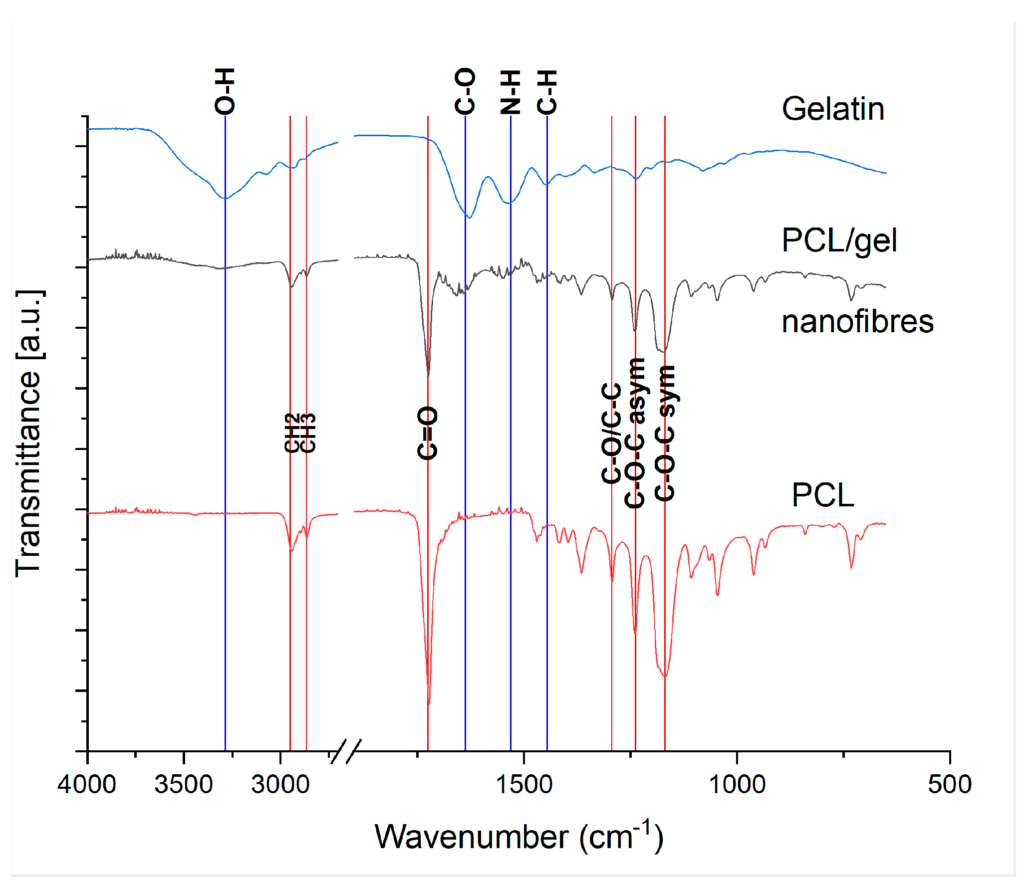
3.5. PCL/Gelatine Sponge Characterisation—Fibre Composition by FTIR
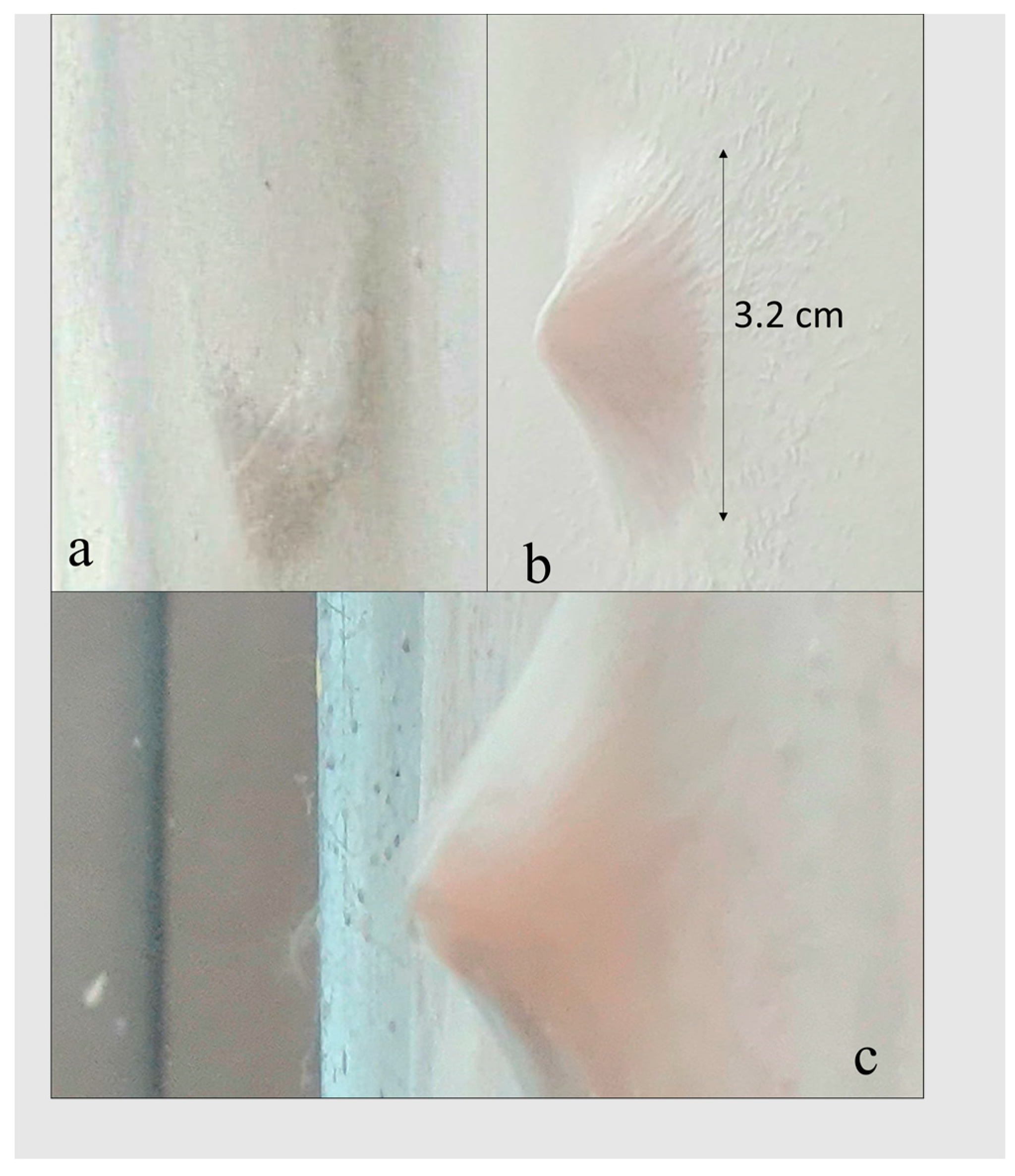
3.6. PCL/Gelatine Sponge Characterisation—Morphology and Hydrophilicity
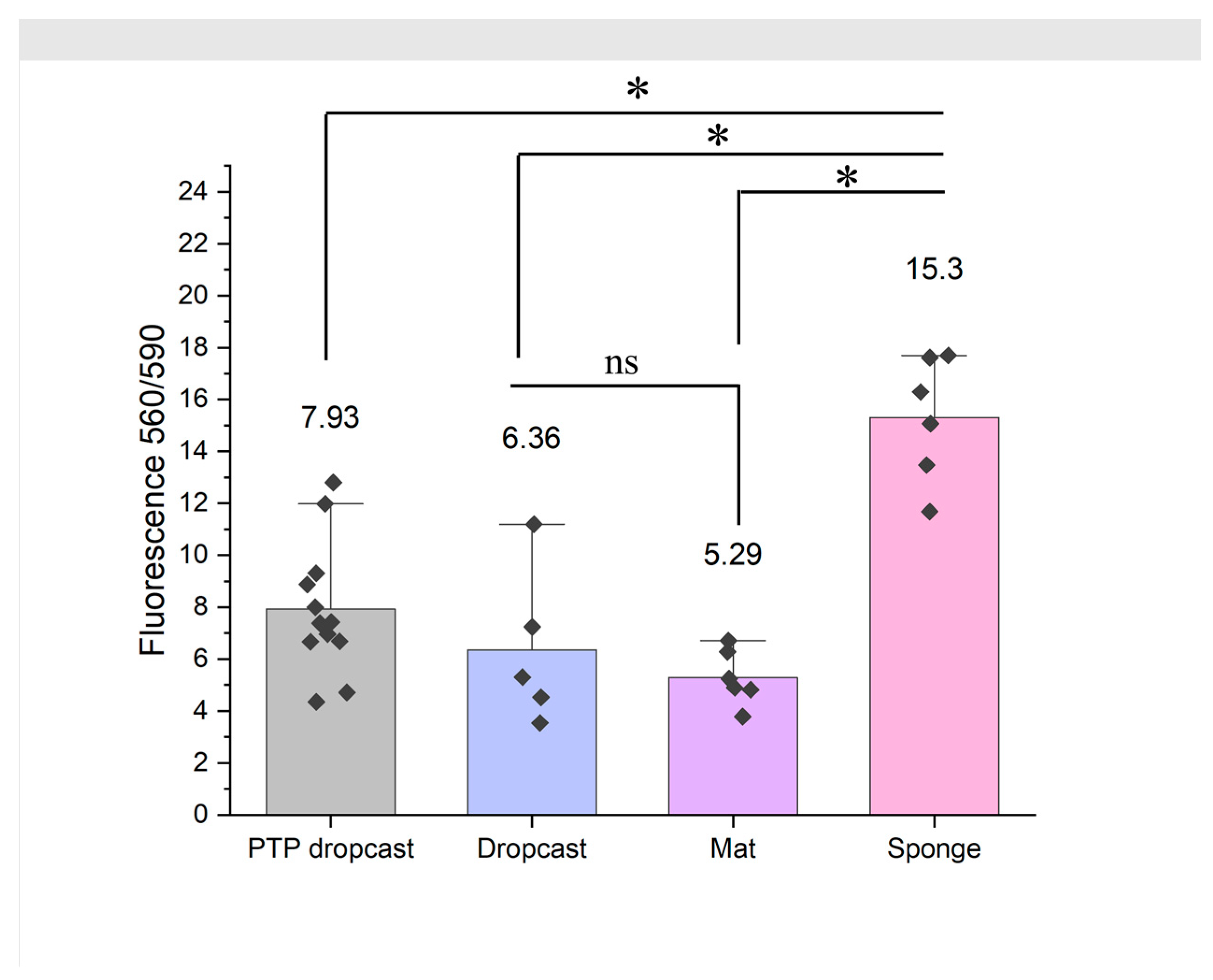
3.7. 3D PCL/Gel Sponges Support Superior Growth of Dermal Fibroblasts
4. Discussion
5. Conclusions
Author Contributions
Funding
Data Availability Statement
Acknowledgments
Conflicts of Interest
Appendix A

References
- Martins, A.; Araujo, J.V.; Reis, R.L.; Neves, N.M. Electrospun nanostructured scaffolds for tissue engineering applications. Nanomedicine 2007, 2, 929–942. [Google Scholar] [CrossRef] [PubMed]
- Tan, H.-L.; Kai, D.; Pasbakhsh, P.; Teow, S.-Y.; Lim, Y.-Y.; Pushpamalar, J. Electrospun cellulose acetate butyrate/polyethylene glycol (CAB/PEG) composite nanofibers: A potential scaffold for tissue engineering. Colloids Surf. B Biointerfaces 2020, 188, 110713. [Google Scholar] [CrossRef] [PubMed]
- Finkemeier, C.G. Bone-grafting and bone-graft substitutes. J. Bone Jt. Surg. 2002, 84, 454–464. [Google Scholar] [CrossRef] [PubMed]
- Khan, I.; Ibrar, A.; Abbas, N.; Saeed, A. Recent advances in the structural library of functionalized quinazoline and quinazolinone scaffolds: Synthetic approaches and multifarious applications. Eur. J. Med. Chem. 2014, 76, 193–244. [Google Scholar] [CrossRef] [PubMed]
- Su, Y.C.; Toftdal, M.S.; Le Friec, A.; Dong, M.; Han, X.J.; Chen, M.L. 3D Electrospun Synthetic Extracellular Matrix for Tissue Regeneration. Small Sci. 2021, 1, 2100003. [Google Scholar] [CrossRef]
- Lim, M.M.; Sultana, N. In vitro cytotoxicity and antibacterial activity of silver-coated electrospun polycaprolactone/gelatinee nanofibrous scaffolds. 3 Biotech 2016, 6, 211. [Google Scholar] [CrossRef] [PubMed]
- Nosar, M.N.; Salehi, M.; Ghorbani, S.; Beiranvand, S.P.; Goodarzi, A.; Azami, M. Characterization of wet-electrospun cellulose acetate based 3-dimensional scaffolds for skin tissue engineering applications: Influence of cellulose acetate concentration. Cellulose 2016, 23, 3239–3248. [Google Scholar] [CrossRef]
- Khorshidi, S.; Karkhaneh, A. Hydrogel/fiber conductive scaffold for bone tissue engineering. J. Biomed. Mater. Res. Part A 2018, 106, 718–724. [Google Scholar] [CrossRef]
- Al-Baadani, M.A.; Yie, K.H.R.; Al-Bishari, A.M.; Alshobi, B.A.; Zhou, Z.X.; Fang, K.; Dai, B.W.; Shen, Y.D.; Ma, J.F.; Liu, J.S.; et al. Co-electrospinning polycaprolactone/gelatine membrane as a tunable drug delivery system for bone tissue regeneration. Mater. Des. 2021, 209, 109962. [Google Scholar] [CrossRef]
- Anjum, S.; Rahman, F.; Pandey, P.; Arya, D.K.; Alam, M.; Rajinikanth, P.S.; Ao, Q. Electrospun Biomimetic Nanofibrous Scaffolds: A Promising Prospect for Bone Tissue Engineering and Regenerative Medicine. Int. J. Mol. Sci. 2022, 23, 9206. [Google Scholar] [CrossRef]
- Hutmacher, D.W. Scaffolds in tissue engineering bone and cartilage. Biomaterials 2000, 21, 2529–2543. [Google Scholar] [CrossRef] [PubMed]
- Li, W.J.; Tuli, R.; Okafor, C.; Derfoul, A.; Danielson, K.G.; Hall, D.J.; Tuan, R.S. A three-dimensional nanofibrous scaffold for cartilage tissue engineering using human mesenchymal stem cells. Biomaterials 2005, 26, 599–609. [Google Scholar] [CrossRef] [PubMed]
- Svensson, A.; Nicklasson, E.; Harrah, T.; Panilaitis, B.; Kaplan, D.L.; Brittberg, M.; Gatenholm, P. Bacterial cellulose as a potential scaffold for tissue engineering of cartilage. Biomaterials 2005, 26, 419–431. [Google Scholar] [CrossRef] [PubMed]
- Moutos, F.T.; Freed, L.E.; Guilak, F. A biomimetic three-dimensional woven composite scaffold for functional tissue engineering of cartilage. Nat. Mater. 2007, 6, 162–167. [Google Scholar] [CrossRef] [PubMed]
- Razal, J.M.; Kita, M.; Quigley, A.F.; Kennedy, E.; Moulton, S.E.; Kapsa, R.M.I.; Clark, G.M.; Wallace, G.G. Wet-Spun Biodegradable Fibers on Conducting Platforms: Novel Architectures for Muscle Regeneration. Adv. Funct. Mater. 2009, 19, 3381–3388. [Google Scholar] [CrossRef]
- Seki, K.; Shimizu, M.; Miyasaka, K.; Ogura, T.; Hosoda, K. Aligning Collagen Fibers by Cyclic Mechanical Stretch for Efficiently Muscle Cell Actuator. In Proceedings of the 2016 IEEE International Conference on Robotics and Biomimetics (Robio), Qingdao, China, 3–7 December 2016; IEEE: San Francisco, CA, USA, 2016; pp. 1197–1202. [Google Scholar]
- Aviss, K.J.; Gough, J.E.; Downes, S. Aligned Electrospun Polymer Fibres for Skeletal Muscle Regeneration. Eur. Cells Mater. 2010, 19, 193–204. [Google Scholar] [CrossRef] [PubMed]
- Zhang, L.; Wang, L.G.; Hu, P. Fabrication of tissue engineering scaffolds via multi-jet and component alternate electrospinning. Adv. Biomater. VI 2005, 288–289, 67–70. [Google Scholar] [CrossRef]
- Yousefzadeh, M.; Latifi, M.; Amani-Tehran, M.; Teo, W.E.; Ramakrishna, S. A Note on the 3D Structural Design of Electrospun Nanofibers. J. Eng. Fibers Fabr. 2012, 7, 17–23. [Google Scholar] [CrossRef]
- Duan, G.G.; Jiang, S.H.; Jerome, V.; Wendorff, J.H.; Fathi, A.; Uhm, J.; Altstadt, V.; Herling, M.; Breu, J.; Freitag, R.; et al. Ultralight, Soft Polymer Sponges by Self-Assembly of Short Electrospun Fibers in Colloidal Dispersions. Adv. Funct. Mater. 2015, 25, 2850–2856. [Google Scholar] [CrossRef]
- Gupta, P.; Perez-Mancera, P.A.; Kocher, H.; Nisbet, A.; Schettino, G.; Velliou, E.G. A Novel Scaffold-Based Hybrid Multicellular Model for Pancreatic Ductal Adenocarcinoma-Toward a Better Mimicry of the in vivo Tumor Microenvironment. Front. Bioeng. Biotechnol. 2020, 8, 290. [Google Scholar] [CrossRef]
- Teo, W.E.; Inai, R.; Ramakrishna, S. Technological advances in electrospinning of nanofibers. Sci. Technol. Adv. Mater. 2011, 12, 013002. [Google Scholar] [CrossRef] [PubMed]
- Zavan, B.; Gardin, C.; Guarino, V.; Rocca, T.; Maya, I.C.; Zanotti, F.; Ferroni, L.; Brunello, G.; Chachques, J.C.; Ambrosio, L.; et al. Electrospun PCL-Based Vascular Grafts: In Vitro Tests. Nanomaterials 2021, 11, 751. [Google Scholar] [CrossRef] [PubMed]
- Cheng, M.; Qin, Z.Y.; Hu, S.; Yu, H.Y.; Zhu, M.F. Use of electrospinning to directly fabricate three-dimensional nanofiber stacks of cellulose acetate under high relative humidity condition. Cellulose 2017, 24, 219–229. [Google Scholar] [CrossRef]
- Cai, S.B.; Xu, H.L.; Jiang, Q.R.; Yang, Y.Q. Novel 3D Electrospun Scaffolds with Fibers Oriented Randomly and Evenly in Three Dimensions to Closely Mimic the Unique Architectures of Extracellular Matrices in Soft Tissues: Fabrication and Mechanism Study. Langmuir 2013, 29, 2311–2318. [Google Scholar] [CrossRef] [PubMed]
- Sun, B.; Long, Y.Z.; Yu, F.; Li, M.M.; Zhang, H.D.; Li, W.J.; Xu, T.X. Self-assembly of a three-dimensional fibrous polymer sponge by electrospinning. Nanoscale 2012, 4, 2134–2137. [Google Scholar] [CrossRef] [PubMed]
- Sanie-Jahromi, F.; Eghtedari, M.; Mirzaei, E.; Jalalpour, M.H.; Asvar, Z.; Nejabat, M.; Javidi-Azad, F. Propagation of limbal stem cells on polycaprolactone and polycaprolactone/gelatine fibrous scaffolds and transplantation in animal model. Bioimpacts 2020, 10, 45–54. [Google Scholar] [CrossRef] [PubMed]
- Safi, I.N.; Al-Shammari, A.M.; Ul-Jabbar, M.A.; Hussein, B.M.A. Preparing polycaprolactone scaffolds using electrospinning technique for construction of artificial periodontal ligament tissue. J. Taibah Univ. Med. Sci. 2020, 15, 363–373. [Google Scholar] [CrossRef]
- Chong, L.H.; Lim, M.M.; Sultana, N. Fabrication and Evaluation of Polycaprolactone/Gelatine-Based Electrospun Nanofibers with Antibacterial Properties. J. Nanomater. 2015, 2015, 970542. [Google Scholar] [CrossRef]
- Rose, J.B.; Sidney, L.E.; Patient, J.; White, L.J.; Dua, H.S.; El Haj, A.J.; Hopkinson, A.; Rose, F. In vitro evaluation of electrospun blends of gelatine and PCL for application as a partial thickness corneal graft. J. Biomed. Mater. Res. Part A 2019, 107, 828–838. [Google Scholar] [CrossRef]
- Van der Schueren, L.; De Schoenmaker, B.; Kalaoglu, O.I.; De Clerck, K. An alternative solvent system for the steady state electrospinning of polycaprolactone. Eur. Polym. J. 2011, 47, 1256–1263. [Google Scholar] [CrossRef]
- Jabur, A.R.; Al-Hassani, E.S.; Al-Shammari, A.M.; Najim, M.A.; Hassan, A.A.; Ahmed, A.A. Evaluation of Stem Cells’ Growth on Electrospun Polycaprolactone (PCL) Scaffolds Used for Soft Tissue Applications. In Proceedings of the International Conference on Technologies and Materials for Renewable Energy, Environment and Sustainability, Tmrees17, Beirut, Lebanon, 21–24 April 2017; Volume 119, pp. 61–71. [Google Scholar] [CrossRef]
- Daelemans, L.; Steyaert, I.; Schoolaert, E.; Goudenhooft, C.; Rahier, H.; De Clerck, K. Nanostructured Hydrogels by Blend Electrospinning of Polycaprolactone/Gelatine Nanofibers. Nanomaterials 2018, 8, 551. [Google Scholar] [CrossRef] [PubMed]
- Yang, W.H.; Tarng, Y.S. Design optimization of cutting parameters for turning operations based on the Taguchi method. J. Mater. Process. Technol. 1998, 84, 122–129. [Google Scholar] [CrossRef]
- Khanlou, H.M.; Ang, B.C.; Talebian, S.; Afifi, A.M.; Andriyana, A. Electrospinning of polymethyl methacrylate nanofibers: Optimization of processing parameters using the Taguchi design of experiments. Text. Res. J. 2015, 85, 356–368. [Google Scholar] [CrossRef]
- Nezadi, M.; Keshvari, H.; Yousefzadeh, M. Using Taguchi design of experiments for the optimization of electrospun thermoplastic polyurethane scaffolds. Adv. Nano Res. 2021, 10, 59–69. [Google Scholar] [CrossRef]
- Estellés, J.M.; Vidaurre, A.; Dueñas, J.M.M.; Cortázar, I.C. Physical characterization of polycaprolactone scaffolds. J. Mater. Sci.-Mater. Med. 2008, 19, 189–195. [Google Scholar] [CrossRef]
- Wu, C.M.; Hsu, C.H.; Su, C.I.; Liu, C.L.; Lee, J.Y. Optimizing parameters for continuous electrospinning of polyacrylonitrile nanofibrous yarn using the Taguchi method. J. Ind. Text. 2018, 48, 559–579. [Google Scholar] [CrossRef]
- Leach, M.K.; Feng, Z.Q.; Tuck, S.J.; Corey, J.M. Electrospinning Fundamentals: Optimizing Solution and Apparatus Parameters. JOVE J. Vis. Exp. 2011, 47, e2494. [Google Scholar] [CrossRef]
- Dong, S.L.; Maciejewska, B.M.; Lissner, M.; Thomson, D.; Townsend, D.; Millar, R.; Petrinic, N.; Grobert, N. Unveiling the Mechanism of the in Situ Formation of 3D Fiber Macroassemblies with Controlled Properties. ACS Nano 2023, 17, 6800–6810. [Google Scholar] [CrossRef]
- Gil-Castell, O.; Badia, J.D.; Ribes-Greus, A. Tailored electrospun nanofibrous polycaprolactone/gelatine scaffolds into an acid hydrolytic solvent system. Eur. Polym. J. 2018, 101, 273–281. [Google Scholar] [CrossRef]
- Lee, B.H.; Shirahama, H.; Cho, N.J.; Tan, L.P. Efficient and controllable synthesis of highly substituted gelatine methacrylamide for mechanically stiff hydrogels. RSC Adv. 2015, 5, 106094–106097. [Google Scholar] [CrossRef]
- Nezarati, R.M.; Eifert, M.B.; Cosgriff-Hernandez, E. Effects of Humidity and Solution Viscosity on Electrospun Fiber Morphology. Tissue Eng. Part C Methods 2013, 19, 810–819. [Google Scholar] [CrossRef]
- Murphy, C.M.; Haugh, M.G.; O’Brien, F.J. The effect of mean pore size on cell attachment, proliferation and migration in collagen-glycosaminoglycan scaffolds for bone tissue engineering. Biomaterials 2010, 31, 461–466. [Google Scholar] [CrossRef] [PubMed]
- Gu, Z.H.; Fan, S.A.; Kundu, S.C.; Yao, X.; Zhang, Y.P. Fiber diameters and parallel patterns: Proliferation and osteogenesis of stem cells. Regen. Biomater. 2023, 10, rbad001. [Google Scholar] [CrossRef] [PubMed]
- Abouelela, A.R.; Al Ghatta, A.; Verdía, P.; Koo, M.S.; Lemus, J.; Hallett, J.P. Evaluating the Role of Water as a Cosolvent and an Antisolvent in HSO4-Based Protic Ionic Liquid Pretreatment. ACS Sustain. Chem. Eng. 2021, 9, 10524–10536. [Google Scholar] [CrossRef]


| Sponge Quality Score | Observation |
|---|---|
| 1 | No electrospinning or mostly dripping |
| 2 | Electrospinning with some dripping or unstable Taylor cone |
| 3 | Stable electrospinning, continuous fibre formation |
| 4 | Some fibres do not deposit flat |
| 5 | Sponge production |
| Level | Concentration SNR | Feed Rate SNR | Working Distance SNR | Voltage SNR |
|---|---|---|---|---|
| 1 | 2 | 10 | 6 | 5 |
| 2 | 4 | 4 | 7 | 4 |
| 3 | 11 | 3 | 4 | 8 |
| Delta | 9 | 7 | 3 | 4 |
| Rank | 1 | 2 | 4 | 3 |
Disclaimer/Publisher’s Note: The statements, opinions and data contained in all publications are solely those of the individual author(s) and contributor(s) and not of MDPI and/or the editor(s). MDPI and/or the editor(s) disclaim responsibility for any injury to people or property resulting from any ideas, methods, instructions or products referred to in the content. |
© 2023 by the authors. Licensee MDPI, Basel, Switzerland. This article is an open access article distributed under the terms and conditions of the Creative Commons Attribution (CC BY) license (https://creativecommons.org/licenses/by/4.0/).
Share and Cite
Howard, C.J.; Paul, A.; Duruanyanwu, J.; Sackho, K.; Campagnolo, P.; Stolojan, V. The Manufacturing Conditions for the Direct and Reproducible Formation of Electrospun PCL/Gelatine 3D Structures for Tissue Regeneration. Nanomaterials 2023, 13, 3107. https://doi.org/10.3390/nano13243107
Howard CJ, Paul A, Duruanyanwu J, Sackho K, Campagnolo P, Stolojan V. The Manufacturing Conditions for the Direct and Reproducible Formation of Electrospun PCL/Gelatine 3D Structures for Tissue Regeneration. Nanomaterials. 2023; 13(24):3107. https://doi.org/10.3390/nano13243107
Chicago/Turabian StyleHoward, Chloe Jayne, Aumrita Paul, Justin Duruanyanwu, Kenza Sackho, Paola Campagnolo, and Vlad Stolojan. 2023. "The Manufacturing Conditions for the Direct and Reproducible Formation of Electrospun PCL/Gelatine 3D Structures for Tissue Regeneration" Nanomaterials 13, no. 24: 3107. https://doi.org/10.3390/nano13243107
APA StyleHoward, C. J., Paul, A., Duruanyanwu, J., Sackho, K., Campagnolo, P., & Stolojan, V. (2023). The Manufacturing Conditions for the Direct and Reproducible Formation of Electrospun PCL/Gelatine 3D Structures for Tissue Regeneration. Nanomaterials, 13(24), 3107. https://doi.org/10.3390/nano13243107