Abstract
A supercapacitor is an energy storage device that has the advantage of rapidly storing and releasing energy compared to traditional batteries. One powerful method for creating a wide range of materials is combustion synthesis, which relies on self-sustained chemical reactions. Specifically, solution combustion synthesis involves mixing reagents at the molecular level in an aqueous solution. This method allows for the fabrication of various nanostructured materials, such as binary and complex oxides, sulfides, and carbon-based nanocomposites, which are commonly used for creating electrodes in supercapacitors. The solution combustion synthesis offers flexibility in tuning the properties of the materials by adjusting the composition of the reactive solution, the type of fuel, and the combustion conditions. The process takes advantage of high temperatures, short processing times, and significant gas release to produce well crystalline nanostructured materials with a large specific surface area. This specific surface area is essential for enhancing the performance of electrodes in supercapacitors. Our review focuses on recent publications in this field, specifically examining the relationship between the microstructure of materials and their electrochemical properties. We discuss the findings and suggest potential improvements in the properties and stability of the fabricated composites based on the results.
1. Introduction
The increasing demands for renewable energy have driven the development of novel energy sources, including wind and solar technologies. However, the economic aspects of these approaches are still under consideration partly due to cost and the inability to service during the source period. To make these technologies competitive, research into energy storage systems, such as fuel cells and supercapacitors, has intensified over the last few decades [1,2,3]. The task is to develop an energy storage system that allows cheap energy storage during lean hours and deliver it later.
The supercapacitor, also known as an ultra-capacitor, is an energy storage device that can store and release energy much faster than traditional batteries [4,5,6]. Although they are still inferior to conventional batteries in energy density, they have a higher power density and longer cycle life than conventional batteries. They are widely used in applications that require high power output, such as electric vehicles, renewable energy systems, and consumer electronics [7]. Two main mechanisms of charge accumulation realize the energy storage in supercapacitors:
- non-faradaic, in which the accumulation of charges is realized completely electrostatically via Cologne forces between the electronic charges of the electrode and the ionic charges of the electrolyte at the interface of electrode/electrolyte, thus forming an electrical double layer;
- faradaic where the accumulation of charges is exclusively non-electrostatic in nature and occurs due to the flow of electronic charges resulting from redox reactions between the ions of the electrolyte and the molecules (or atoms) of the electroactive material of the electrode.
Based on these two energy storage mechanisms, the supercapacitors are classified into three types: electric double-layer capacitors (EDLCs) (with non-faradaic or electrostatic charge storage system), pseudocapacitors (with faradaic or electrochemical charge storage system), and hybrid SCs (with the combination of faradaic and non-faradaic charge storage systems).
EDLCs capacitors involve only electrostatic energy storage mechanism (do not involve chemical reactions to store and release energy) thus providing much higher charge/discharge rate than batteries and high power density. The energy density in EDLCs is much higher than in conventional capacitors, which is conditioned with higher specific capacitance (SC) value of EDLCs. As the charge accumulation occurs at the electrode/electrolyte interface, the specific surface area (SSA) of electrode materials plays a crucial role in the SC value of supercapacitors [8].
Different types of carbon-based materials including graphene, activated carbon, mesoporous carbon, carbon aerogel, and carbon nanotubes are used in fabrication of electrodes for EDLCs, as it is well known that such materials provide high SSA and high electrical conductivity, which is another crucial parameter for obtaining high values of SC [9,10,11]. Despite the energy density in EDLCs being much higher than in conventional capacitors, it is still lower than in batteries. One way to enhance SC is to fabricate pseudocapacitors in which the pseudo capacitance arises due to faradaic redox reactions between the electrode active material and electrolyte at their contact interface and can exceed the double-layer capacitance more than 100 times [12,13,14], as electrode materials for pseudocapacitors serve transition metal oxides such as NiO, MnO2, Co3O4, and Fe3O4 etc. [15,16,17,18]. Although they provide high pseudo capacitance due to redox reactions, they suffer from bad electric conductivity, which obstructs the increase of SC. An effective way to overcome this obstacle and increase the SC is to fabricate hybrid supercapacitors in which hybrid electrodes are developed by integrating the metal oxides with the carbon-based network. In the hybrid electrodes, carbon functions as a conductive channel for charge transfer and improves the overall conductivity, while pseudo capacitance arises from the metal oxides [19,20,21,22,23]. The classification of the supercapacitors is discussed in detail in [3,6,7,19].
Several approaches have been employed to synthesize materials for supercapacitor applications, including hydrothermal/solvothermal, chemical bath deposition, sol-gel, and chemical precipitation processes [24,25,26,27,28,29,30,31,32]. Hydrothermal and solvothermal synthesis methods are similar, except for the solution being aqueous or non-aqueous with much higher temperature need for the latter one and used to synthesize a variety of transition metal oxides, including for pseudocapacitor applications [25,26]. These methods permit fabrication of well crystalline, highly monodispersed particles with controllable size and shape, while typically require high temperature and pressure. Chemical bath deposition is another approach primarily used for preparation nano films and not applicable for all oxides [27,28]. It is low-cost, low-temperature and also suitable for large-scale deposition. Significant efforts are applied to prepare better quality oxide-based nanostructures using the sol-gel process [29,30]. The method is simple, cheap, and allows products of high purity and good homogeneity. Chemical precipitation is also a simple method for large-scale synthesis of nano-size materials including transition metal oxides/hydroxides [31,32]. The challenge is to control the morphology of particles due to the fast precipitation.
Combustion synthesis (CS) is an energy-saving approach that allows easy scale-up and contentious technology for fabricating various materials [33,34,35]. The CS is based on the paradigm of self-sustained exothermic reactions, which take place without any extremal heat sources. Solution combustion synthesis (SCS) is a type of CS method when reagents are mixed on the molecular level as an aqueous solution. SCS is a highly versatile and cost-effective method for fabrication of a wide range of supercapacitor electrode materials. It allows for the synthesis of materials with tailored properties, including particle size distribution, crystallinity, surface area, and chemical composition. By adjusting the composition of the reactive solution, fuel type, and combustion regimes, researchers can fine-tune the properties of the materials produced [36,37,38]. Additionally, SCS generates significant gas release during the synthesis process, which leads to the formation of nanostructured materials with a large specific surface area. This feature enhances the overall performance of the electrode materials. Taking into account its affordability, versatility, and control over material properties, solution combustion synthesis emerges as an attractive method for preparing electrode materials for supercapacitors.
This review critically analyzes the recent publications on the SCS of materials used in construction of SC’s electrodes. We also outline challenges and suggest specific directions of research that will allow the improvement of the electrochemical characteristics of such materials. To better understand the principles of SCS, its driving parameters, and their role in synthesis process, first we will briefly summarize the fundamentals of the method.
2. Solution Combustion Synthesis: Fundamentals
The nature of the solution combustion synthesis was described elsewhere [39,40,41]. Initial precursors are solid powders of different oxidizers (typically metal nitrites) and fuels (e.g., glycine, citric acid, and urea). These powders have high solubility in solvent (e.g., water). The reactive solution is the oxidizer and fuel dissolved in a desired ratio in a solvent. The reaction in such a solution can be initiated in two different regimes. Volume combustion synthesis (VCS) implies preheating the whole solution to the self-ignition temperature (Tig). After reaching Tig, the reaction begins uniformly along the whole volume of the reactive media, resulting in the formation of the desired solid product (Figure 1).
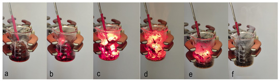
Figure 1.
Sequence of frames illustrating the volume combustion synthesis mode: (a) initial solution installed slightly above the hot plate; (b) preheating stage; (c) reaction initiation stage; (d) volume combustion synthesis stage; (e) cooling stage; (f) final product.
The self-propagating high-temperature synthesis (SHS) regime involves local preheating of the solution to initiate the reaction, followed by the combustion wave propagating along the reactive media, leading to the formation of the solid product (Figure 2). In both cases, no external heat sources are required for reaction occurrence after initiation, because a lot of energy is released due to exothermic chemical reactions.
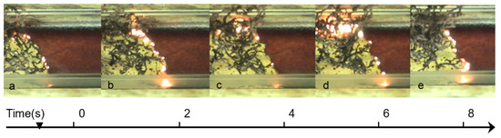
Figure 2.
Sequence of frames recorded at different time, (t, s): (a) t = 0; (b) t = 2; (c) t = 4; (d) t = 6; (e) t = 8; illustrating the self-propagating combustion synthesis mode: reaction propagates from left to right with constant velocity.
Let us demonstrate the reaction in the system that consists of the aqueous solution of metal nitrite (oxidizer) and glycine (fuel). The overall reaction can be presented in the following scheme:
where φ is a valence of the metal; m—number of molecules of tied water in nitrate; 2n—number of moles of fuel used per one mole of oxidizer.
Assigning 18n/5ν = φ, the above equation can be re-written in the following way:
It can be seen that if φ equals one, then no external (atmospheric) oxygen is required for complete oxidation of the fuel. For φ < 1 (φ > 1), the fuel-lean (rich) system is considered. For example, for nickel (II) nitrate hexahydrate (m = 6) and glycine system, which is widely discussed in this review, the overall reaction is typically presented as follows:
The amount of the released heat and thus maximum reaction temperature depends on the chemical composition of the reactive solutions, i.e., parameters φ and m in Equation (2), as well as on parameters of the surrounding atmosphere (pressure, composition: oxygen, nitrogen, air, argon).
Thermodynamic equilibrium phase composition of the combustion product and corresponding adiabatic (absence of heat losses) combustion temperature may be calculated by using different thermodynamic software packages [42], including the program THERMO, specifically designed for CS systems [43]. To make such calculations, one has to know the standard enthalpies of formation for precursors and all possible combustion products, as well as their specific heats [44].
Figure 3 illustrates the specific features of thermodynamic calculations. The φ-m parametric map shows that adiabatic combustion temperature varies between 850–2500 K as a function of the fuel-to-oxidizer ratio and amount of water. It is more important that the phase composition of the equilibrium solid products also change; complex oxide (NiFe2O4) exists when φ and m are less than one; oxides (FeO, NiO, Fe3O4) at φ and m are between 1 and 2; and metals/alloys (Ni, Fe, FeNi) are at large values of φ and m.
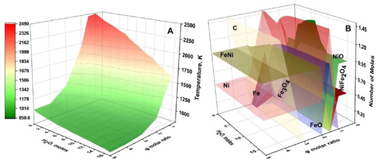
Figure 3.
Calculated adiabatic temperature (A) and distribution of equilibrium solid products (B) for Fe(NO3)3 + Ni(NO3)2 + C6H12N4 + H2O system depending on C6H12N4/(Fe(NO3)3 + Ni(NO3)2) molar ratio (φ) and amount of H2O (m). (Reprinted with permission from [45]. Copyright 2023 Springer Nature).
Volume combustion synthesis is characterized by self-ignition temperature (Tig). This temperature is defined by the rates of heat release (q+) and heat losses (q−) [46]. In the classical case, it is assumed that a homogeneously premixed reactive mixture is placed in a vessel of volume V and the area of the external surface S, that the temperature and concentration are uniform at each point of the vessel, and that heat exchange (q−) with the environment occurs according to Newton’s law [47]:
where α is the heat transfer coefficient and T0 is the temperature of the environment.
The heat that is generated (q+) throughout the volume of the reaction mixture depends on reaction kinetics, which are typically assumed to be of Arrhenius type [47]:
Q is the heat of the reaction and Ea is the activation energy.
Equations (4) and (5) describe the heat balance in the reaction vessel. It is useful to present this relationship graphically (Figure 4). Straight lines 2–6 display the heat losses to the environment with different α, in accordance with Equation (4), and curve 1 shows the rate of heat generation in accordance with Equation (5). Let us consider, for example, conditions 1 and 2, assuming that the initial reaction mixture has the ambient temperature T0. Since, at this temperature, the q+ is higher than q−, the self-preheating process starts and continues until heat balance is reached at point A1, where the rates of heat transfer and heat dissipation are equal:
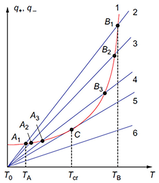
Figure 4.
Diagram of thermal explosion in a homogeneous reactive system. (Reprinted with permission from [42]. Copyright 2015 CRC Press Taylor & Francis Group).
It can be seen that the equilibrium at point A1 is stable. Indeed, in the case of overheating, the heat losses begin to prevail, returning the system to point A1. Similarly, if over-cooling takes place, the heat generation returns the system to point A1. This condition corresponds to the steady-state process in a chemical reactor.
If you reduce the heat transfer coefficient α (lines 3–5), then the point of intersection (Ai; i = 2,3) shifts to higher temperatures until the heat loss line and heat release curve are tangent at point C. With further decrease of α, the heat release rate (curve 1) is above the heat loss (e.g., line 6) at any temperature. The steady state cannot exist, and the system is self-heated with acceleration. Tangency at point C is the critical condition (Tig), which separates the steady-state “slow” reaction from the thermal explosion, i.e., VCS [42]:
Equations (6) and (7) gives equation for critical conditions [42]:
The above analysis aims to show that Tig depends on kinetics and boundary conditions. It means that the same reactive solution being under different temperatures of the heating device (e.g., furnace) will have different ignition temperatures. In addition, different reactive solutions typically have different Tig under similar heating conditions. It is also essential that after reaction initiation, the temperature rapidly increases, reaching maximum Tm = Tig + Q/cρ (c—specific heat and ρ—density of the products), which is much higher than the temperature of the heating device. The temperature–time history of the system after the reaction (cooling stage) depends on the heat loss conditions. The above conclusions are important because the microstructure and phase composition and thus properties of the synthesized solid products depend on the time–temperature history of the VCS process.
Self-propagating high-temperature (SHS) regime in the homogeneous media (reactive solution) can be described by classical combustion theory [47], which postulates that after local short-term thermal initiation of reactive matter, a combustion wave arises propagating along the media with a certain velocity u. The planar steady-state combustion wave propagation is described by using the equations of thermal conductivity and chemical kinetics [47]:
where Q, heat of reaction; and η, the degree of conversion.
A typical structure of a combustion wave is given in Figure 5. Due to the strong (exponential) dependence of combustion front velocity on temperature, the chemical transformation happens primarily within the narrow zone in the vicinity of maximal combustion temperature Tm, which for adiabatic conditions is Tm = Tad ~ T0 + Q/ρc. In the theory of frontal combustion, a key problem is finding out proper conditions for steady wave propagation at constant velocity u.
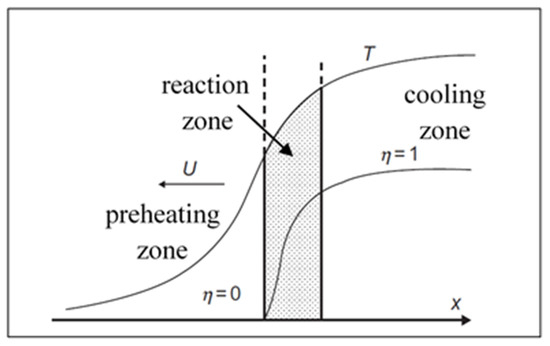
Figure 5.
Combustion wave structure: preheating zone (left), reaction zone (shadowed), and cooling zone (right). (Reprinted with permission from [42]. Copyright 2015 CRC Press Taylor & Francis Group).
Velocity u is an eigenvalue of the problem (9–10) formulated at the following boundary conditions: at X = −∞, T = T0, η = 0; X = +∞, T = Tm, η = 1. Using the relation between the temperature gradient (dT/dx) and the degree of conversion (η) within the reaction zone suggested in [48]:
where λ is thermal conductivity and ηmax is the degree of conversion at T = Tm.
Matching solutions for the three zones (Figure 5), one obtains the expression for combustion velocity [48]:
The SHS regime is much easier to control. In the steady-state planar combustion wave, the time–temperature history along the whole sample is identical, leading to the uniform microstructure and thus properties of the obtained materials. Both VCS and SHS regimes were used to synthesize a variety of materials, including oxides, nitrides, and alloys [36,49,50]. In this review, we analyze recent reports on SCS of the materials, which have potential applications in supercapacitors.
3. Combustion Synthesis of Materials for SC’s Applications
Many different materials for fabricating electrodes in supercapacitor applications were produced using self-sustained reactions in solutions. Nanostructured transition metal oxides have attracted considerable interest in electrochemistry due to their high theoretical capacity and good chemical stability [15,51,52]. The electrochemical performance of such materials is strongly dependent on their morphology and composition, which significantly influence the transport rate of electrons and structural stability of electrodes in energy conversion and storage systems [53,54,55,56,57]. Transition metal sulfides, as a new class of pseudo-capacitive materials, have also been extensively studied because of their capabilities to provide high energy density. Fabrication of transition metal oxides and sulfides by SCS allows precise control of the microstructure of the fabricated materials [58,59]. Below, we overview recent publications in the SCS field, focusing on the microstructures and electrochemical properties of the fabricated materials. Specifically, we discuss examples of nickel (Ni)- and manganese (Mn)-based compositions, which are considered to be excellent candidates for supercapacitor applications.
3.1. Nickel-Based Compositions
Among the materials studied, nickel-oxide is especially attractive because of its high theoretical capacitance, resourcefulness, facile fabrication protocols, low cost, environment friendliness, and good thermal and chemical stability. Many reports have been made on synthesizing various NiO nanostructures, including nanoflowers, nanoflakes, porous nano/microspheres, and nanofibers, prepared via multiple synthesis methods, including SCS (Table 1).

Table 1.
NiO prepared using various methods and their supercapacitor performance. (Reprinted with permission from [52]. Copyright 2016 Elsevier B.V. All rights reserved).
However, pseudo-capacitors based on such materials usually need better rate capability due to the slow faradaic reactions and low electrical conductivity. Despite significant progress in modifying pristine nickel oxide, up to now, there is a great challenge to simultaneously achieve high specific capacitance, rate capability, and cycling stability. One can improve the supercapacitance performance by controlling the material construction, forming composites, and developing new nickel-based materials. Here, we review recent works for the combustion synthesis of Ni-based composites with enhanced electrochemical characteristics.
NiO/ZnO nanocomposite was synthesized by a simple and facile gel combustion method from metal nitrides using citric acid as a fuel, followed by relatively long (3 h) calcination at 500 °C [72]. XRD analysis revealed the presence of cubic NiO and hexagonal ZnO phases, with essentially no impurities. The average crystallite size, estimated by Scherrer’s equation, was ~25 nm. SEM studies showed that the powder has a sphere-like morphology with an average particle size of ~60 nm.
Electrochemical measurements were performed in the KOH-based electrolyte by a three-electrode cell setup. Cyclic voltammetry (CV) at the scan rates between 5 mV/s and 100 mV/s displays a typical pseudo-capacitive behavior with characteristic redox peaks (Figure 6a). The calculated values for specific capacitance (SC) were 111, 124, 136, 166, 146, and 198 F g−1 for 100, 50, 25, 10, and 5 mVs−1 respectively. Figure 6b demonstrates typical Galvano-static charge-discharge (GCD) curves at current densities of 0.5–4 mA/cm2. SC values determined by the method were 450, 390, 312, 270, and 174 Fg−1 for current densities of 0.5, 1, 2, 3, and 4 mA/cm2, respectively. Figure 6c displays the cyclic stability of NiO/ZnO nanocomposites, showing SC retention (SCR) of 74.7% after 5000 cycles and a current density of 3 mA/cm2.
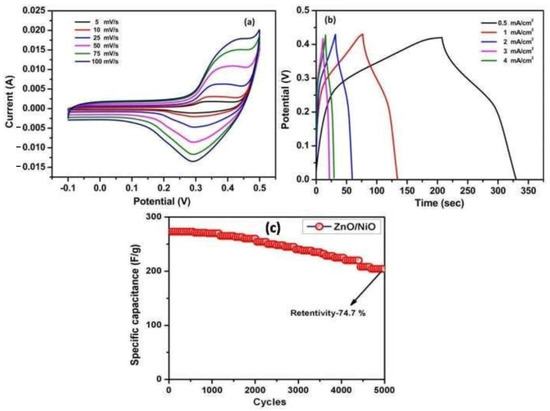
Figure 6.
(a) Cyclic voltammetry curve; (b) charge–discharge curve; (c) cyclic stability curve for NiO/ZnO nanocomposites. (Adapted with permission from ref. [72]. Copyright 2020. BEIESP).
The observed effect of an increase of specific capacitance with a decrease in current densities was explained as follows: at lower current densities, ionic charge carriers have enough time to diffuse through the electrode/electrolyte low so fast that the accumulation of ions on the working electrode surface is minimal, resulting in small SC. Thus, the authors demonstrated that a combustion-based approach could fabricate impurity-free complex NiO/ZnO nanopowder (60 nm). The obtained material possesses SC ~400 F/g at current densities 1 mA/cm2 and SCR ~75% after 5000 cycles at a current density of 3 mA/cm2.
Nickel-based hybrid metal oxides (NixMe1−xOy: Me = Co, Fe, Mn, Mo, Cu, or Cr) were produced by mixing metal nitrates precursors with glycine, followed by VCS mode and calcination at 500 °C for 6 h [73]. The SEM studies show foam-like morphology for all materials. The specific surface area (BET) of all investigated foams was found to be between 6.8 and 83.4 m2/g, with pore diameter ranging between 8.5 and 12.3 nm (see Table 2). TEM imaging of the as-prepared oxides reveals that NixCo1−xOy, NixMo1−xOy, and NixCr1−xOy foams involve spherical particles (Figure 7b,e,g, respectively) with an average particle size in the range of 26 to 29 nm. The random agglomerates in flake-like structures were obtained for other oxides (Figure 7a,c,d,f). The most important result of this study is that substituting the Ni in NiO structure with other metals (e.g., by Mo and Cr) may significantly increase the specific surface area of the powder.
Table 2.
Textural properties of NiO and the hybrid binary NixM1−xOy materials. (Reprinted with permission from [73]. Copyright 2022 The Royal Society of Chemistry).
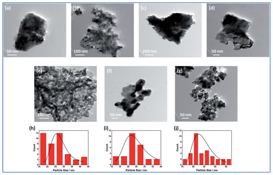
Figure 7.
Morphologies of (a) NiO; (b) NixCo1−xOy; (c) NixFe1−xOy; (d) NixMn1−xOy; (e) NixMo1−xOy; (f) NixCu1−xOy, and (g) NixCr1−xOy. Particle size distribution of (h) NixCo1−xOy; (i) NixMo1−xOy; (j) NixCr1−xOy. (Reprinted with permission from [73]. Copyright 2022 The Royal Society of Chemistry).
In addition, the electrocatalytic performance of the fabricated hybrid Ni-based materials was investigated towards oxygen evolution reaction in an alkaline medium. It was shown that while among all hybrid oxides, the higher BET ~84 m2/g was observed for NixMo1−xOy composition, the NixCr1−xOy powder with BET ~30 m2/g showed the best electrocatalytic performance, exhibiting the lowest (404 mV) overpotential at a current density of 10 mA/cm2, onset potential of ~1.6 V, and Tafel slope~53 mV/dec. It means that not only specific surface area but also the synergism between metals is an important parameter to tune up the material’s electrochemical properties.
Complex CNTs/C/NiMoO4 composites were fabricated by one-step volume solution combustion method using citric acid as a fuel and ammonium heptamolybdate (NH4)6MoO24 as molybdenum source [74]. The overall reaction was expected to proceed as follows:
To study the effect of the fuel amount on the material’s microstructure and electrochemical properties, the φ value in the reactive solution was varied: 6.5/9, 13/9, 26/9, 39/9, and 52/9. The CNTs/C/NiMoO4 composites were also obtained by adding an appreciable quantity of acid-treated CNTs (25 mg, 50 mg, and 100 mg denoted as 25-CNTs/C/NiMoO4, 50-CNTs/C/NiMoO4, and 100-CNTs/C/NiMoO4, respectively, into the optimized fuel-to-oxidant ratio 13/9). The influence of φ on the specific surface area, pore volumes, and size of the materials is shown in Table 3.
Table 3.
Microstructure parameters of the samples. (Reprinted with permission from [74]. Copyright 2018 Elsevier).
The thermodynamic calculations suggest that the adiabatic combustion temperature possesses its maximum at the stoichiometric φ value (i.e., 26/9 for the considered system) and decreases with increasing or decreasing of φ value. This effect explains observed changes in the materials’ specific surface area, pore volume, and crystallinity. Well crystalline powder with the lowest BET formed after combustion of the stoichiometric solution (Table 3). It was also shown that in crystalline samples, the observed diffraction peaks correspond to the monoclinic NiMoO4, which belongs to a space group of C2/m.
SEM analysis reveals that most samples are porous agglomerates of irregular plate- and grain-like particles. Unlike other materials, the sample obtained from the reactive solution with φ = 13/9 is composed of uniform spherical particles with a narrow size distribution of 20–30 nm. For this reason, this composition was selected to prepare the CNTs/NiMoO4 powders. Electrochemical performance of as-prepared C/NiMoO4 composites was studied using CV and GCD in a typical three-electrode system (Figure 8). Analysis of the discharged curves at current density 1 A/g allowed estimation of the specific capacitances of the materials (Table 4).
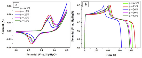
Figure 8.
The CV curves (a) of samples at scan rate of 10 mV/s and galvanostatic charge–discharge curves (b) of samples at the current density of 1 A/g. (Reprinted with permission from [74]. Copyright 2018 Elsevier).
Table 4.
Some structural and electrochemical characteristics. (Reprinted with permission from [74]. Copyright 2018 Elsevier).
It can be seen that material fabricated from the reactive solution with φ = 13/9 possesses the highest SC (859 F/g). The addition of the electroconductive CNTs allows an increase in the value up to ~1037 F/g. The asymmetric supercapacitors were fabricated based on the 50-CNTs/C/NiMoO4 composites as an anode and the AC as a cathode. The polypropylene membrane and the 2 M KOH aqueous solution were used as the separator and the electrolyte, respectively. Again, the SC was calculated by analysis of the GCD curves. In such a configuration, the CNTs/C/NiMoO4//AC exhibited a considerably high SC of ~70 F/g at the scan rate of 0.2 A/g within 0–1.5 V, and the energy density of 32.6 and 18.2 Wh/kg with the power density of 150.5 and 8509 W/kg, respectively. This asymmetric device showed a well-cycle stability, in which the capacitance retained 96.5% after 1500 cycles.
Several outcomes from this work can be outlined:
- The fuel-to-oxidizer ratio is an effective parameter to control the crystallinity and specific surface area of the synthesized materials.
- One may reach sufficient material crystallinity without long-term calcination.
- One may obtain relatively high SC at the specific surface area ~50 m2/g.
- The addition of CNTs improves the electrochemical properties.
Various Ni-based carbon-nitrogen containing composites, i.e., Ni2(CO3)(OH)2, Ni3(NO3)2(OH)4, NiC2O4, have been synthesized via a one-step salt (NaCl)-assisted solution combustion synthesis using glucose (C6H12O6) as a fuel at a temperature of 215 °C [75]. The molar ratio of ξ = NaCl: Ni(NO3)2 was adjusted to be 0, 0.5, 1.0, and 1.5. The XRD patterns of the as-synthesized samples showed that: (i) for a reactive solution with ξ = 0, the main product phase was Ni3(NO3)2(OH)4; (ii) for ξ = 0.5, a ternary composite composed of Ni3(NO3)2(OH)4, nickel oxalate hydrate NiC2O4·2H2O, and Ni2(CO3)(OH)2·H2O formed; (iii) for ξ = 1.0, the NiC2O4·2H2O and Ni2(CO3)(OH)2·H2O were the dominant products, with a high amount of the latter phase; (iv) for ξ = 1.0, only the NiO phase was detected.
SEM images for samples synthesized with various amounts of NaCl show that salt amount affects the morphology of the as-prepared products (Figure 9). Composites fabricated from a solution with ξ = 0.5 (Figure 9B) are composed of rectangular nanoparticles with a length of ~150 nm and a width of ~90 nm. Further increase of the salt concentration (ξ = 1.0; Figure 9C) results in a decrease of a number of rectangular nanoparticles. Combined with the XRD results, these rectangular nanoparticles are identified as NiC2O4·2H2O phase. It was concluded that the formation of NiC2O4·2H2O and Ni2(CO3)(OH)2 phases is related to the presence of NaCl. Thus, the main synthetic outcome of the work is that it was shown that salts (NaCl; NaF; NaBr; NaI; KCl) catalyze the formation of “unusual” Ni-based phases, such as nickel oxalate (NiC2O4·2H2O) and otwayite (Ni2(CO3)(OH)2·H2O.
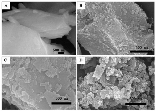
Figure 9.
SEM images of (A) ξ = 0.0; (B) ξ =0.5; (C) ξ = 1.0; and (D) ξ =1.5. (Reprinted with permission from [75]. Copyright 2018 Elsevier).
The electrochemical performance of the resulting products was characterized by a standard three-electrode configuration in a 6.0 M KOH aqueous electrolyte. Composite, obtained by salt-assisted solution combustion synthesis from solution with ξ = 1.0, exhibited the highest specific capacitance (1420 F/g at 1 A/g) and cycling performance (60.0% after 2000 cycles) among all synthesized materials (Table 5). A hybrid supercapacitor with a positive electrode made from composite fabricated by using a solution with ξ = 1.0 as a positive electrode and active carbon as a negative electrode delivers high energy density (32.5 Wh/kg at a power density of 310.2 W/kg) and good long-term cycling stability (over 62.5% at 1000 cycles).
Table 5.
Capacitive performance of different Ni-based electrode materials. (Reprinted with permission from [75]. Copyright 2018 Elsevier).
Table 5 also summarizes data on SC and CR on different Ni-based materials. It can be concluded that ternary Ni-C-O phases functionalized by high CNTs or graphene are the promising candidates for super capacitor applications.
As mentioned above, nickel sulfide-based composites are other materials to consider for the SC’s application. For example, nickel sulfide/reduced graphene oxide (NiS/RGO) powders were prepared by solution combustion method using nickel nitrate and graphene oxide as oxidants together with thioacetamide (C2H5NS), as well as glycine as the fuels [81]. It was shown that a 1:1 mole mixture of nickel nitrate and thioacetamide after synthesis resulted in the formation of 100% nickel disulfide (NiS2). Adding 2 moles of glycine to this solution led to a composite consisting of 67% nickel sulfide (NS) and 37% NiS2. Combustion of reactive nitrate–thioacetamide–glycine solution with a 1:1:3 mole ratio produced 100% of NiS. A NiS/RGO material was fabricated by adding GO to the 1:1:3 mole solution. Graphene oxide (GO) was in situ reduced during the combustion process to produce NiS/RGO nanocomposites. These results again outline the versatility of the combustion synthesis method to one-step synthesis of various composites.
SEM images of nickel disulfide powder show a porous and foamy morphology involving agglomerated spherical nanoparticles (~50 nm). The NiS and NiS/RGO materials possess bulky microstructures formed by strongly agglomerated nanoparticles. TEM images of these materials revealed that NiS nanoparticles (~50 nm) are uniformly distributed on the RGO sheets (Figure 10b).
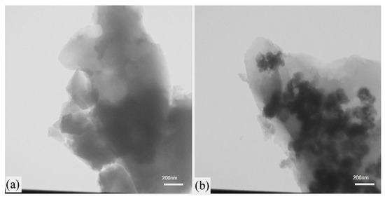
Figure 10.
TEM images of the combusted powders: (a) NiS and (b) NiS/RGO. (Reprinted with permission from [81]. Copyright 2021 Elsevier).
Figure 11 shows the CV curves of the NiS and NiS/RGO materials vs. Ag/AgCl electrode in the potential range of 0 to 0.4 V at the scanning rates of 5 to 50 mV/s. The oxidation and reduction peaks in the CV curves indicate the pseudocapacitive behavior of the samples. The NiS/RGO composite powders showed relatively high SC = 305 F/g at a current density of 1.1 A/g. The high conductivity of RGO and distribution of nickel sulfide nanoparticles on RGO sheets led to the high-capacity retention of 91% after 3000 cycles.
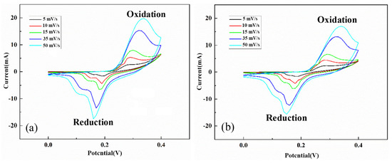
Figure 11.
The CV curves of NiS (a) and NiS/RGO (b) materials at the various scan rates. (Reprinted with permission from [81]. Copyright 2021 Elsevier).
To conclude this section, the fabrication approach based on the self-sustained reactions allows practical synthesis of essentially any Ni-based composites. It was also shown that by varying synthesis parameters, such as fuel-to-oxidizer ratio, type of fuel, and temperature–time schedule, one might control the phase composition, shape, and size of the produced particles. The most critical structural characteristics that influence the electrochemical properties are phase composite, the specific surface area of the powder, and the amount and morphology of the electroconductive part of the composite (e.g., carbon). In Ni-based systems, the SCS permits the synthesis of nanostructured composites with SSA up to 100 m2/g and essentially any desired phase composition and amounts of electroconductive phase. The reported recorded values of specific capacitance are up to ~1500 F/g at 1 A/g with capacitance retention in the range of 60–100%, which is dependent on the operational conditions.
3.1.1. Manganese Based Materials
Nanostructured manganese oxide nanoparticles were prepared via the SCS method at 250 °C and 300 °C (denoted as C250 and C300) by using a stoichiometric mixture of manganese acetate dihydrate (C6H9MnO6·2H2O) and urea (CH4N2O) [82]. The material fabricated at a lower temperature (C250) consisted of two phases, i.e., tetragonal hausmannite (Mn3O4) and magnesium monoxide (MoO). The C300 sample possessed a pure Mn3O4 structure. The average crystallite sizes for both materials were around 25 nm.
Electrochemical behavior was studied by cyclic voltammetry (CV) in 1.0 M Na2SO4 aqueous solution at room temperature in a potential window of 0 to 0.5 V (vs. Ag/AgCl) at a scan rate of 100 mV/s. It was shown that the specific capacitance was 128 F/g and 32 F/g for the C250 and C300 samples, respectively. The effect was attributed to the higher specific surface area of the material prepared at lower temperatures. The obtained specific capacitances appeared comparable with those reported for Mn3O4-based materials fabricated by other methods [83,84].
The carbon–manganese (C-Mn3O4/MnO) composites were prepared using a one-step combustion method via initiating the reactions in manganese acetate anhydrous–ethanol solution [84]. In the combustion process, manganese acetate converted into Mn3O4/MnO (MMs) phases, while the carbon formed by the incomplete combustion of carbonaceous material was embedded into MMs, creating C-Mn3O4/MnO composites (C-MMs). It was reported that the molar ratio of Mn3O4 and MnO in C-MMs was 17:3. There were no apparent carbon-related diffraction peaks in C-MMs, which was related to the poor crystallinity of carbon. For comparison, Mn3O4/MnO (MMs) material was fabricated via the calcination of C4H6MnO4·4H2O at 350 °C for 3 h in air. FESEM image shows the spherical-like morphology with an average diameter of about 43 nm for C-MMs (Figure 12a) and platelet structure with a length of around 300 nm for MMs powders (Figure 12b). The HRTEM images of C-MMs (Figure 12c,d) presents the atomic structure. The d-spacing of 0.138, 0.204, and 0.309 nm are assigned to the (402), (220), and (112) planes of Mn3O4, respectively. The d-spacing of 0.257 nm and 0.222 nm are ascribed to (111) and (200) planes of MnO, respectively.
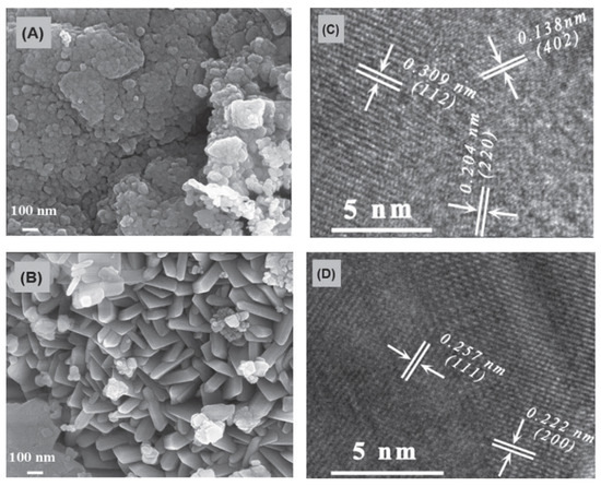
Figure 12.
FESEM images of C-Mn3O4/MnO composites (A) and Mn3O4/MnO composites (B); HRTEM images of C-Mn3O4/MnO composites (C,D). (Reprinted with permission from [85]. Copyright 2023 IOP Publishing).
The electrochemical properties of the as-prepared samples as electrode materials for supercapacitors were evaluated by cyclic voltammetry, charge–discharge, electrochemical impedance, and cycling stability. The calculated specific capacitance of C-MMs was 204 F/g at 1 A/g, which is more than two times larger than that for MMs (90 F/g at 1 A/g). Table 6 reviews the capacitance of manganese oxide-based materials. Charge transfer resistances calculated from Nyquist plots were 0.67 and 42.4 for C-MMs and MMs, which means that C-MMs possess much smaller charge transfer resistance. Charge–discharge cyclic stability for C-MMs at a current density of 1 A/g and within a potential window of −0.1~0.4 V was extremely high (188%) after 5500 cycles.
Table 6.
Comparison of properties of manganese oxide-base electrodes. (Data taken from the references cited in the last column of the table).
The influences of fuel type (glycine (G) or urea (U)), fuel to oxidizer ratio (φ), and stabilizer (KCl, KNO3) for α-MnO2 phase formation via VCS mode were investigated in [92] without any additional calcination steps. When comparing samples prepared using glycine as a fuel with different φ values (φ = 0.15, 0.25, 0.5, 1, 2), the XRD patterns showed Mn3O4 as the dominant phase for the samples G-1 and G-2 and Mn2O3 as the dominant phase for the G-0.15, G-0.25, and G-0.5 ones. This effect was attributed to the higher combustion temperature and stronger reduction conditions for a reactive solution with high φ. In the case of urea for φ = 2, the MnO was a predominate phase, while for systems within the φ range 0.8–1, the Mn2O3 phase dominated. Further decrease of φ leads to the formation of oxides with higher valances, i.e., Mn2O3 and MnO2. At φ = 0.25 and less, the final product involves two phases, i.e., β-MnO2 (ICDD 24-0735) and α-MnO2 (ICDD 44-0141) polymorphs, with a much higher amount of the former phase. The use of KNO3 and KCl stabilizers leads to an increase in the amount of α-MnO2 phase in the final product. For example, adding 2 moles of KNO3 to the initial reactants of a U-0.8 sample results in formation a single α-MnO2 phase. The stability of α-MnO2 was attributed to the presence of K+ cations.
Particle size analysis (Figure 13) shows that the powders synthesized using urea as a fuel had slightly smaller sizes than those fabricated using glycine. This effect was explained by the greater gas volume produced during the synthesis in urea-based systems. According to Figure 14 the smallest particle sizes were obtained for φ = 0.5–1 for urea and φ = 1 for glycine, which correspond to the reactive solutions with the highest synthesis temperature. High temperature led to an increased reaction rate, causing the products to form more rapidly, but also provided faster cooling rates, which may diminish the sintering and agglomeration processes.
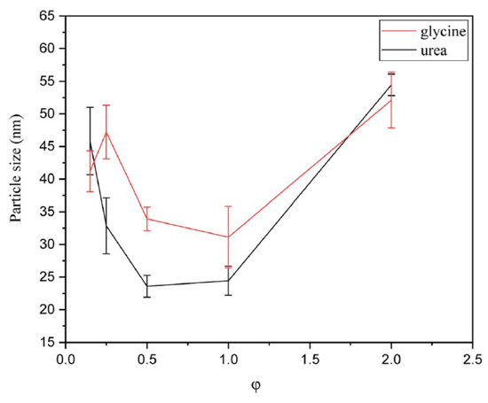
Figure 13.
Particle size of the powders synthesized by glycine and urea in various φ ratios. (Reprinted with permission from [92]. Copyright 2023 Royal Society of Chemistry).
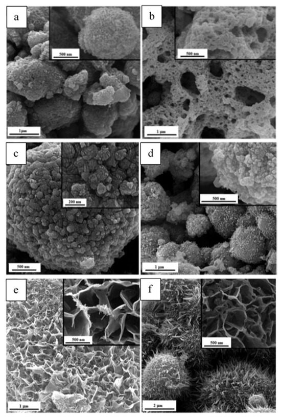
Figure 14.
FESEM micrographs of the as-synthesized samples (a) G-0.25, and (b) G-1; (c) U-0.15, (d) U-1; (e) U-K-0.8, (f) U-K-0.9. (Reprinted with permission from [92]. Copyright 2023 Royal Society of Chemistry).
Figure 14 illustrates the morphology of different powders. As shown in Figure 14a, G-0.25 powder reveals a granular morphology, indicating agglomerates of Mn2O3 nanoparticles with a ridged surface, while the G-1 one (Figure 14b) displays a lacy morphology. The amounts of released gases were higher in sample G-1, which caused greater porosity and more cavities. The FESEM image of the U-0.15 sample (Figure 14c) shows that the MnO2 nanoparticles have a cauliflower-like morphology, while U-1 powder (Figure 14d) exhibits a granular morphology. Figure 14e,f illustrates the micrographs of the samples synthesized by adding KNO3. A dandelion-like morphology with a needle/flake-like surface was revealed for the α-MnO2 nanoparticles. In addition, it was reported that increasing the amount of stabilizer led to a finer morphology of the fabricated materials.
These results demonstrate the versatility of a combustion-based method allowing fabrication of essentially all polymorphs of magnesium oxide with different morphology and particle size. Such studies are an important step to produce materials with defined structure and thus desired properties.
The carbon-coated ZnMn2O4 nanocrystallites were successfully fabricated by a VSC mode using manganese (II) nitrate tetrahydrate and zinc nitrate hexahydrate (Zn(NO3)2·6H2O) as oxidizers and urea as a fuel. In addition, polyethylene glycol (PEG) was used as a microstructure directing agent [93]. PEG with two molecular weights (200 and 6000) allowed the control of the material pore structure. It served as a precursor for forming a carbon shell on the oxide grains, inhibiting crystallite growth and enhancing the powder’s electronic conductivity. For simplicity, the samples are indexed as ZM-n-Y, where n = 2 for PEG-200 used in the synthesis and 6 for PEG-6000, and Y represents the PEG/nitrates weight ratio expressed as Y/12.8. ZM-0 represents the powder synthesized without the addition of PEG.
XRD analysis indicates that all samples exhibit a single tetragonal ZnMn2O4 phase. The specific surface area (Stotal) and crystallite size (Dc) are presented in Table 7. The ZM-0 has an average crystallite size of 32 nm, which is larger than for the powders synthesized with PEG addition. The PEG-added powders’ BET-specific surface areas were 27–47 m2/g, substantially higher than that (7.8 m2/g) of ZM-0. The data indicate that the presence of PEG during synthesis is an effective tool to control powder morphology.
Table 7.
Structural characteristics specific capacitance of C-ZnMn2O4 materials. (Reprinted with permission from [93]. Copyright 2018 Elsevier).
SEM and TEM studies reveal that the nanoparticles in all samples have an average size of 10–50 nm with nano-porous hierarchical structures. HRTEM images (Figure 15) show the existence of the carbon shell and suggest a high crystallinity of the powders despite a very short synthesis time.
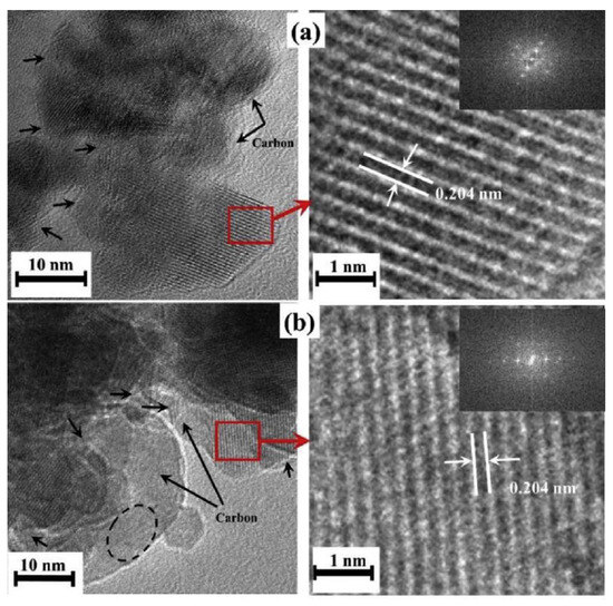
Figure 15.
HRTEM images (left side) and highly magnified selected regions (right side) of (a) ZM-6-1; (b) ZM-6-2. Inset: FFT patterns of the corresponding regions. (Reprinted with permission from [93]. Copyright 2018 Elsevier).
Electrochemical measurements showed that the PEG-added samples had specific capacitances in the 75–150 F/g range, which were substantially higher than that (38 F/g) of the ZM-0 electrode (Table 7). The specific capacitance was found to increase with increasing specific surface area as well as residue carbon content. The ZM-6-1 electrode was mainly used for further characterization. It was shown that the electrode retained a specific capacitance of 69 F/g with an efficiency of 99.4% at a high current density of 5 A/g. A cycle life test of the ZM-6-1 electrode was performed by repeating the GS charge–discharge test between 0.1 and 1.0 V at a current density of 2.5 Ag−1. A total of 100% of the capacitance after 5500 cycles was recorded. These results indicate the extremely high electrochemical stability of the Mn-based materials.
A facile large-scale SCS method using glycine as a fuel was reported to produce MnO2/MnCo2O4 composites [94]. The effects of the amount of glycine (φ = 7/9, 14/9, 28/9, 42/9: S1–S4 samples) on the fabricated materials’ phase composition, morphology, and electrochemical properties were investigated. It is reported that all fabricated samples involve fcc spinel MnCo2O4. The microstructural parameters of the fabricated materials are presented in Table 8.
Table 8.
Microstructure parameters obtained by BET analyses of the samples. (Reprinted with permission from [94]. Copyright 2016 Elsevier).
SEM studies revealed that the morphologies of all samples consist of porous agglomerates of nanoparticles with random granular shapes. The sizes of nanoparticles and agglomerates are 30–50 and 250–300 nm, respectively. All samples have a similar pore size distribution in the 2–4 nm range. The uniform distribution of mesopores should favor electrolyte penetration into the electrode and thus provide more active spots for ion diffusion during the redox reaction.
The S2 powder possessed the smallest nanoparticles (30–35) and agglomerates (200 nm) compared to other samples. This material was selected for the electrochemical characterization. The maximum specific capacitance of 458 F/g is achieved at a current density of 0.5 A/g, with a decent cycling efficiency of 65.5% after 5000 cycles.
To enhance electrochemical performance, manganese–cobalt-oxides with different molar ratios of Mn/Co were also synthesized and investigated on the base of optimum fuel/oxidizer molar ratio. It was shown that by increasing the Mn/Co ratio, the products transformed from spinel MnCo2O4 granular aggregates to a mixture of MnO2/MnCo2O4 composite. The TEM images of the powder synthesized from the reactive solution with Mn:Co:glycine molar ratio of 3:4:31.5/9 are shown in Figure 16. It was reported that the average particle size was about 28 nm. The maximum specific capacitance of 497 F/g was achieved at a current density of 0.5 A/g and a cycling efficiency of 60% after 5000 cycles. Comparison of supercapacitor performance of the MnCo2O4-based materials prepared by different methods are summarized in Table 9.
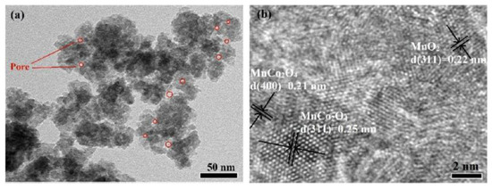
Figure 16.
Bright field (a) and high-resolution (b) TEM images of the MnO2/MnCo2O4 composite. (Reprinted with permission from [94]. Copyright 2016 Elsevier).
Table 9.
Specific capacitance of MnCo2O4-based materials prepared by different methods. (Reprinted with permission from [94]. Copyright 2016 Elsevier).
Recall that SCS allows fabrication of essentially all polymorphs of magnesium oxide with different morphology and particle size. Overall, we may conclude that in general manganese-based materials possess less specific capacitance (<1000 F/g) as compared to Ni-based ones (up to 1500 F/g), but they demonstrate excellent SC retaining properties.
3.1.2. Other Compositions
Other nanostructured materials synthesized by the SCS method and tested for electrochemical properties include iron oxide-based and cobalt oxide-based composites. A few recent results are discussed below.
The nanostructured iron oxides with controllable morphology and composition were successfully prepared via one-step VCS mode (300 °C) by tuning the fuel (glycine) to oxidizer molar ratio [106]. The TEM images of the fabricated powders are shown in Figure 17. It can be seen that powder obtained by direct decomposition of nitrite (φ = 0) has an urchin-like morphology (Figure 17a). The needle has a large aspect ratio with a diameter of ~5 nm and a length of ~200 nm. The powder produced from the reactive solutions with φ = 0.5 and 1.0 (Figure 17b,c) exhibits a porous sheet-like structure with a large quantity of single ~10 nm pores and a small amount of irregular-shaped pores with a diameter above 50 nm. When the φ value increases to 1.5 (Figure 17d), the produced material involves uniform and well-dispersed nanoparticles of nearly hexagonal geometry with an average diameter of ~50 nm. The specific surface area and pore size of the products were:
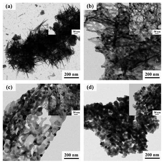
Figure 17.
TEM images of SCS products with different φ (the upper-right inset shows the corresponding high magnification image): (a) φ = 0; (b) φ = 0.5; (c) φ = 1.0; (d) φ = 1.5. (Reprinted with permission from [106]. Copyright 2018 Elsevier).
- 27 m2/g and wide pore size distribution with a maximum at 20 nm (φ = 0).
- 54 m2/g and narrow pore size distribution with peak at ~3 nm (φ = 0.5).
- 56 m2/g and pore size 2 nm (φ = 1.0)
- 18 m2/g and the main peak of pores diameter at ~5 nm (φ = 1.5).
XRD and XPS analysis reveal that the phase composition of the products changed from amorphous α-Fe2O3 for φ = 0 case to crystalline α-Fe2O3 for φ = 0.5 and α-Fe2O3/Fe3O4 composites for larger φ, with a graduate increase of the amount of Fe3O4 with a rise in the amount of fuel.
Figure 18 shows the cycling performance of different anodes at the current density of 1 A/g. As can be seen, the φ = 0.5 and 1.0 anodes exhibit a sharp decline in discharge specific capacity in the initial 50 cycles, and then the SC increases significantly to ~1200 mAh/g after 500 cycles. In contrast, for the φ = 0 and 1.5 anodes, a slight decrease in discharge capacity can be detected in the initial 50 cycles. Then, the SC stabilizes at ~400 mAh/g and ~600 mAh/g, respectively. The high SC and superior capacity recovery in φ = 0.5 and 1.0 anodes were ascribed to the porous nanosheets morphology and high specific surface area. The porous nanosheets can shorten the transport length of the Li+ band and also supply favorable accessibility for electrons. In turn, the high specific surface area can provide an appropriate electrode/electrolyte interface to facilitate fast charge transfer and minimize polarization effects. For comparison, Table 10 shows the electrochemical performance of different iron oxide anodes reported in the open literature [14,40,41,42,46,47,48].
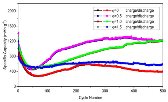
Figure 18.
Cycling performance of different φ anodes at the current density of 1 A/g. (Reprinted with permission from [106]. Copyright 2018 Elsevier).
Table 10.
The electrochemical performance of different iron oxide anodes. (Reprinted with permission from [106]. Copyright 2018 Elsevier).
Co3O4 and Co3O4/CoO nanoparticles have been synthesized by a one-step VCS mode [114]. The molar ratios of citric acid monohydrate and Co(NO3)2·6H2O were fixed to be 3.5/27, 7/27, 14/27(stoichiometry), 21/27 (samples I–IV, correspondingly). The ammonium nitrate (NH4NO3) was used as an additional oxidizer to support the combustion reaction. Some microstructural parameters of the fabricated powders are shown in Table 11. It can be seen that the maximum SSA ~21 m2/g was obtained for sample II (φ = 7/27). SEM images of as-synthesized sample II and after annealing at different temperatures (350; 450; 550 for 3 h) are shown in Figure 19.
Table 11.
The electrochemical performance of different iron oxide anodes. (Reprinted with permission from [114]. Copyright 2014 Elsevier).
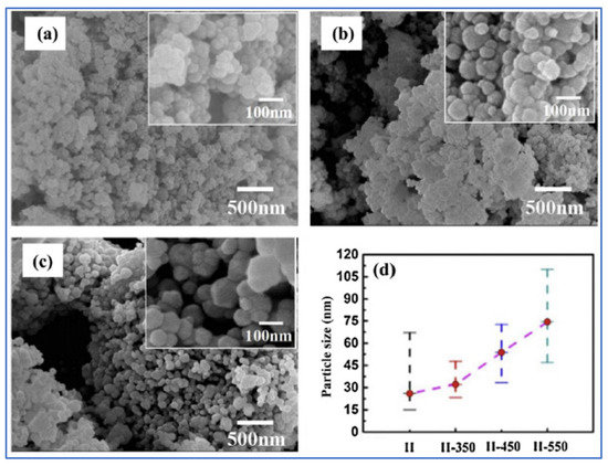
Figure 19.
SEM images of samples II-350 (a); -II-450 (b) and -II-550 (c). Part (d) shows the average particle size and particle size range. (Reprinted with permission from [114]. Copyright 2014 Elsevier).
The CV studies of sample-II before and after annealing at a scan rate of 5 mV/s revealed that all materials possess pseudo-capacitance features with distinct anodic and cathodic peaks. In addition, the sample-II-350 displays a much higher redox peak current density and larger enclosed area than the others, implying better capacitor performance. The reported SC values for sample-II, -II-350, -II-450, and -II-550 were 155, 391, 108, and 65 F/g, respectively. The analysis of the GSC curves obtained at a constant discharge current density of 0.2 A/g gave the following SC values: 180, 363, 121, and 63 F·g−1, for sample-II, -II-350, -II-450, and -II-550, respectively. Sample-350 also demonstrated decent rate performance (286 F/g at 4 A/g) and cycling stability (73.5% retention after 1000 cycles). The results suggest that the electrochemical performance of the material was significantly improved by its annealing at 350 °C for 3 h under a nitrogen atmosphere. The further increase of annealing temperatures resulted in rapid deterioration of the electrochemical performance.
The above examples demonstrate that FeO and CoO-based nanocomposites can be effectively synthesized by the SCS method. Adding ammonium nitrate is a powerful approach to control combustion, which can be used in any SCS system. Optimization of the calcination stage should also be considered, while we believe that materials with desired microstructure and properties can be produced in one SCS step without additional thermal treatment.
4. Future Prospects
The solution combustion synthesis involves multiple parameters that can be utilized to control these structural characteristics. However, researchers have only explored a few of them. For instance, all the materials discussed in the review were synthesized using the volume combustion synthesis mode. This mode involves preheating the reactive mixture to a self-ignition temperature, followed by a thermal explosion of the media. Although this mode is easy to accomplish, it is not the optimal choice for controlling the product’s microstructure. Firstly, it is impossible to uniformly preheat the entire volume, leading to non-uniform synthesis conditions. Secondly, the immediate gas release from the large volume results in an uncontrolled dispersion of the media, again resulting in non-uniform conditions.
On the other hand, the steady-state self-propagating mode (SHS) is a much more controllable approach for material synthesis. The temperature–time schedule remains constant throughout the process, as the reaction front moves progressively. The combustion theory allows for precise prediction and variation of the conditions. Therefore, the first recommendation is to utilize the SHS mode to produce desired materials.
An analysis of the existing literature suggests that the main parameter used by researchers to alter the structural characteristics of materials is the fuel-to-oxidizer ratio (φ). While this is indeed an important parameter, there are several others that can be used to control the process:
- i.
- Amount of bound water in the reactive system, which can affect the phase composition of the materials.
- ii.
- Preliminary drying of the reactive media, which may lead to the formation of specific organic complexes and allow for the fabrication of metastable phases that are challenging to produce using conventional methods.
- iii.
- Oxygen-free fuels, which enable the production of not only oxides but also other types of materials such as metals, alloys, and nitrides.
- iv.
- Gas pressure in the reactor, which can influence the kinetics of combustion reactions during SCS and affect the particle size of the resulting materials.
- v.
- Gasifying agents that can increase the specific surface area of the powder.
- vi.
- Different types of solvents that can serve as oxidizers or fuels, intensifying or inhibiting the process.
- vii.
- Impregnation of the reactive solution into high surface area conductive media (e.g., carbon), followed by SHS, resulting in the one-step formation of hybrid MeOx-C structures suitable for electrochemical applications.
- viii.
- Different types of fuels were used in SCS reactions including glycine (CH4N2O), citric Acid (C6H8O7), urea (CH4N2O), sucrose (C12H22O11), Glycose D-(+)-C6H12O6, hydrazine (H2N-NH2), carbohydrazide (CH6N4O), oxalyhydrazide (C2H6N4O2), and metal hydrazinecarboxylates hydrates (see Table 1 in [115]). The fuel influences the combustion temperature and, hence, the chemical reaction rate and the chemical environment, including the amount of released gas and oxygen concentration. Higher combustion temperatures can lead to higher crystallinity, reduced impurities, and improved structural properties of the resulting materials. However, excessively high temperatures can also lead to sintering or agglomeration of nanoparticles, which may negatively affect the specific surface area. Faster combustion rates and larger gasification typically lead to smaller particle sizes and finer pore structures, which enhance the surface area of synthesized materials, making them more suitable for supercapacitor applications. Using different fuels can optimize the synthesis process and obtain materials with the desired characteristics, such as high surface area, good electrical conductivity, and suitable electrochemical performance for supercapacitor electrodes.
Furthermore, optimizing the SCS conditions allows for the fabrication of materials with desired properties directly in the combustion wave, without the need for any post-thermal treatment. The materials produced are typically well crystalline due to the high temperature in the combustion wave. However, the duration of the high-temperature stage is short, resulting in small particle size powders. Additionally, by controlling the amount of gas phase released during combustion wave propagation, it is possible to obtain materials with high surface area.
The researchers in the field of electrochemistry should take advantage of the extensive knowledge accumulated over more than 50 years of combustion synthesis. By utilizing this knowledge, it is possible to fabricate materials with exceptionally high electrochemical properties.
5. Conclusion Remarks
The synthetic approach, which relies on self-sustained chemical reactions, is a powerful method for creating a wide range of nanostructured materials that are applicable in electrochemistry. There are several advantageous aspects to the combustion-based methods to fabricate electrodes for supercapacitors:
- Versatility: This technique allows for the synthesis of materials with any phase composition.
- Simplicity and energy savings: Complex materials can be produced in a single step with minimal external energy usage.
- Easy scaling up and continuous production: The process can be easily expanded and implemented on a larger scale.
Based on an overview of the topic, the following structural characteristics are crucial for electrochemical applications:
- Phase composition, which takes into account the synergy between different elements.
- Specific surface area.
- Particle and pore size distribution.
- Morphological interaction between oxides and electroconductive phases, such as various carbonaceous materials.
All the above parameters can be precisely controlled by using fundamental knowledge on the combustion phenomenon. Thus, this review suggests that SCS is an attractive approach towards fabrication of materials for supercapacitor applications.
Funding
This research was funded by the Higher Education and Science Committee of the Republic of Armenia (Research project no. 22rl-045). A. Manukyan acknowledges the ADVANCE Research Grants provided by the Foundation for Armenian Science and Technology for the partial financial support.
Data Availability Statement
Data are contained within the article.
Conflicts of Interest
The authors declare no conflict of interest.
References
- Huggins, R.A. Energy Storage: Fundamentals, Materials and Applications, 2nd ed.; Springer: Berlin/Heidelberg, Germany, 2015. [Google Scholar]
- Conway, B.E. Electrochemical Supercapacitors: Scientific Fundamentals and Technological Applications; Springer: Berlin/Heidelberg, Germany, 1999. [Google Scholar]
- Wang, Y.; Song, Y.; Xia, Y. Electrochemical capacitors: Mechanism, materials, systems, characterization and application. Chem. Soc. Rev. 2016, 45, 5925–5950. [Google Scholar] [CrossRef]
- Conway, B.E. Transition from “Supercapacitor” to “Battery” Behavior in Electrochemical Energy Storage. J. Electrochem. Soc. 1991, 138, 1539. [Google Scholar] [CrossRef]
- Gogotsi, Y.; Penner, R.M. Energy Storage in Nanomaterials—Capacitive, Pseudocapacitive, or Battery-like? ACS NANO 2018, 12, 2081–2083. [Google Scholar] [CrossRef]
- Yaseen, M.; Khattak, M.A.K.; Humayun, M.; Usman, M.; Shah, S.S.; Bibi, S.; Hasnain, B.S.U.; Ahmad, S.M.; Khan, A.; Shah, N.; et al. A Review of Supercapacitors: Materials Design, Modification, and Applications. Energies 2021, 14, 7779. [Google Scholar] [CrossRef]
- Şahin, M.E.; Blaabjerg, F.; Sangwongwanich, A. A Comprehensive Review on Supercapacitor Applications and Developments. Energies 2022, 15, 674. [Google Scholar] [CrossRef]
- Tang, L.; Ji, X.; Wu, P.; Luo, H.; Zhu, Y.; Deng, L.; Cheng, S.; Liu, M. Achievement of high energy carbon based supercapacitors in acid solution enabled by the balance of SSA with abundant micropores and conductivity. Electrochim. Acta 2020, 353, 136562. [Google Scholar] [CrossRef]
- Ke, Q.; Wang, J. Graphene-based materials for supercapacitor electrodes—A review. J. Materiomics. 2016, 2, 37–54. [Google Scholar] [CrossRef]
- Wang, X.; Liu, L.; Wang, X.; Bai, L.; Wu, H.; Zhang, X.; Yi, L.; Chen, Q. Preparation and performances of carbon aerogel microspheres for the application of supercapacitor. J. Solid State Electrochem. 2011, 15, 643–648. [Google Scholar] [CrossRef]
- Kaempgen, M.; Chan, C.K.; Ma, J.; Cui, Y.; Gruner, G. Printable thin film supercapacitors using single-walled carbon nanotubes. Nano Lett. 2009, 9, 1872–1876. [Google Scholar] [CrossRef] [PubMed]
- Fleischmann, S.; Mitchell, J.B.; Wang, R.; Zhan, C.; Jiang, D.E.; Presser, V.; Augustyn, V. Pseudocapacitance: From Fundamental Understanding to High Power Energy Storage Materials. Chem. Rev. 2020, 120, 6738–6782. [Google Scholar] [CrossRef] [PubMed]
- Jiang, Y.; Liu, J. Definitions of Pseudocapacitive Materials: A Brief Review. Energy Environ. Mater. 2019, 2, 30–37. [Google Scholar] [CrossRef]
- Wang, J.; Dong, S.; Ding, B.; Wang, Y.; Hao, X.; Dou, H.; Xia, Y.; Zhang, X. Pseudocapacitive materials for electrochemical capacitors: From rational synthesis to capacitance optimization. Natl. Sci. Rev. 2017, 4, 71–90. [Google Scholar] [CrossRef]
- Liang, R.; Du, Y.; Xiao, P.; Cheng, J.; Yuan, S.; Chen, Y.; Yuan, J.; Chen, J. Transition Metal Oxide Electrode Materials for Supercapacitors: A Review of Recent Developments. Nanomaterials 2021, 11, 1248. [Google Scholar] [CrossRef]
- Goel, S.; Tomar, A.K.; Singh, G.; Sharma, R.K. Highly Pseudocapacitive NiO Nanoflakes through Surfactant-Free Facile Microwave-Assisted Route. ACS Appl. Energy Mater. 2014, 1, 1540–1548. [Google Scholar] [CrossRef]
- Lu, Q.; Lattanzi, M.W.; Chen, Y.; Kou, X.; Li, W.; Fan, X.; Unruh, K.M.; Chen, J.G.; Xiao, J.Q. Supercapacitor Electrodes with High-Energy and Power Densities Prepared from Monolithic NiO/Ni Nanocomposites. Angew. Chem. 2011, 50, 6847–6850. [Google Scholar] [CrossRef]
- Toupin, M.; Brousse, T.; Belanger, D. Charge Storage Mechanism of MnO2 Electrode Used in Aqueous Electrochemical Capacitor. Chem. Mater. 2004, 16, 3184–3190. [Google Scholar] [CrossRef]
- Muzaffara, A.; Ahameda, M.B.; Deshmukha, K.; Thirumalai, J. A review on recent advances in hybrid supercapacitors: Design, fabrication and applications. Renew. Sustain. Energy Rev. 2019, 101, 123–145. [Google Scholar] [CrossRef]
- Wang, H.; Yi, H.; Chena, X.; Wang, X. Asymmetric supercapacitors based on nano-architectured nickel oxide/graphene foam and hierarchical porous nitrogen-doped carbon nanotubes with ultrahigh-rate performance. J. Mater. Chem. A 2014, 2, 3223–3230. [Google Scholar] [CrossRef]
- Shan, Y.; Gao, L. Formation and characterization of multi-walled carbon nanotubes/Co3O4 nanocomposites for supercapacitors. Mater. Chem. Phys. 2007, 103, 206–210. [Google Scholar] [CrossRef]
- Poudel, M.B.; Kim, A.R.; Ramakrishan, S.; Logeshwaran, N.; Ramasamy, S.K.; Kim, H.J.; Yoo, D.J. Integrating the essence of metal organic framework-derived ZnCoTe–N–C/MoS2 cathode and ZnCo-NPS-N-CNT as anode for high-energy density hybrid supercapacitors. Compos. Part B 2022, 247, 110339. [Google Scholar] [CrossRef]
- Poudel, M.B.; Kim, H.J. Confinement of Zn-Mg-Al-layered double hydroxide and α-Fe2O3 nanorods on hollow porous carbon nanofibers: A free-standing electrode for solid-state symmetric supercapacitors. Chem. Eng. J. 2022, 429, 132345. [Google Scholar] [CrossRef]
- Kate, R.S.; Khalate, S.A.; Deokate, R.J. Overview of nanostructured metal oxides and pure nickel oxide (NiO) electrodes for supercapacitors: A review. J. Alloys Compd. 2018, 734, 89–111. [Google Scholar] [CrossRef]
- Li, L.; Cheah, Y.; Ko, Y.; Teh, P.; Wee, G.; Wong, C.; Peng, S.; Srinivasan, M. The facile synthesis of hierarchical porous flower-like NiCo2O4 with superior lithium storage properties. J. Mater. Chem. A 2013, 1, 10935–10941. [Google Scholar] [CrossRef]
- Liu, M.; Chang, J.; Sun, J.; Gao, L. A facile preparation of NiO/Ni composites as high-performance pseudocapacitor materials. RSC Adv. 2013, 3, 8003–8008. [Google Scholar] [CrossRef]
- Nagayama, H.; Honda, H.; Kawahara, H. A New Process for Silica Coating. J. Electrochem. Soc. 1988, 135, 2013–2016. [Google Scholar] [CrossRef]
- Inamdar, A.I.; Kim, Y.; Pawar, S.M.; Kim, J.H.; Im, H.; Kim, H. Chemically grown, porous, nickel oxide thin-film for electrochemical supercapacitors. J. Power Sources 2011, 196, 2393–2397. [Google Scholar] [CrossRef]
- Kim, S.I.; Lee, J.S.; Ahn, H.J.; Song, H.K.; Jang, J.H. Facile route to an efficient NiO supercapacitor with a three-dimensional nanonetwork morphology. ACS Appl. Mater. Interfaces 2013, 5, 1596–1603. [Google Scholar] [CrossRef] [PubMed]
- Sreethawong, T.; Chavadej, S.; Ngamsinlapasathian, S.; Yoshikawa, S. A Modified sol–Gel Process-Derived Highly Nanocrystalline Mesoporous NiO With Narrow Pore Size Distribution. Colloids Surf. A Physicochem. Eng. Asp. 2007, 296, 222–229. [Google Scholar] [CrossRef]
- Liu, K.C.; Anderson, M.A. Porous Nickel Oxide/Nickel Films for Electrochemical Capacitors. J. Electrochem. Soc. 1996, 143, 124–130. [Google Scholar] [CrossRef]
- Xing, W.; Li, F.; Yan, Z.; Lu, G.Q. Synthesis and electrochemical properties of mesoporous nickel oxide. J. Power Sources 2004, 134, 324–330. [Google Scholar] [CrossRef]
- Varma, A.; Rogachev, A.S.; Mukasyan, A.S.; Hwang, S. Combustion Synthesis of Advanced Materials: Principles and Applications. Adv. Chem. Eng. 1998, 24, 74–226. [Google Scholar]
- Deshpande, K.; Mukasyan, A.; Varma, A. Direct Synthesis of Iron Oxide Nanopowders by the Combustion Approach: Reaction Mechanism and Properties. Chem. Mater. 2004, 16, 4896–4904. [Google Scholar] [CrossRef]
- Merzhanov, A.G. The Chemistry of Self-Propagating High-Temperature Synthesis. J. Mater. Chem. 2004, 14, 1779–1786. [Google Scholar] [CrossRef]
- Aruna, S.; Mukasyan, A.S. Combustion synthesis and nanomaterials. Curr. Opin. Solid State Mater. Sci. 2008, 12, 44–50. [Google Scholar] [CrossRef]
- Khort, A.; Podbolotov, K.; Serrano-García, R.; Gun’ko, Y.K. One-step solution combustion synthesis of pure Ni nanopowders with enhanced coercivity: The fuel effect. J. Solid State Chem. 2017, 253, 270–276. [Google Scholar] [CrossRef]
- Li, P.Y.; Deng, J.C.; Li, Y.; Liang, W.; Wang, K.; Kang, L.T.; Zeng, S.Z.; Yin, S.H.; Zhao, Z.G.; Liu, X.G.; et al. One-step solution combustion synthesis of Fe2O3/C nano-composites as anode materials for lithium ion batteries. J. Alloys Compd. 2014, 590, 318–323. [Google Scholar] [CrossRef]
- Varma, A.; Mukasyan, A.S.; Rogachev, A.S.; Manukyan, K.V. Solution combustion synthesis of nanoscale materials. Chem. Rev. 2016, 116, 14493–14586. [Google Scholar] [CrossRef]
- Novitskaya, E.; Kelly, J.P.; Bhaduri, S.; Graeve, O.A. A review of solution combustion synthesis: An analysis of parameters controlling powder characteristics. Int. Mater. Rev. 2021, 66, 188–214. [Google Scholar] [CrossRef]
- Siddique, F.; Gonzalez-Cortes, S.; Mirzaei, A.; Xiao, T.; Rafiqd, M.A.; Zhang, X. Solution combustion synthesis: The relevant metrics for producing advanced and nanostructured photocatalysts. Nanoscale 2022, 14, 11806–11868. [Google Scholar] [CrossRef]
- Rogachev, A.S.; Mukasyan, A.S. Combustion for the Material Synthesis; Copyright 2015 CRC Press Taylor & Francis Group: Boca Raton, FL, USA, 2014. [Google Scholar]
- Shiryaev, A.A. Distinctive Features of Thermodynamic Analysis in SHS Investigations. J. Eng. Phys. Thermophys. 1993, 65, 957–962. [Google Scholar] [CrossRef]
- Shiryaev, A.A. Thermodynamics of SHS Processes: Advanced Approach. Int. J. Self-Propagating High Temp. Synth. 1995, 4, 351–362. [Google Scholar]
- Yermekova, Z.; Roslyakov, S.I.; Kovalev, D.Y.; Danghyan, V.; Mukasyan, A.S. One-step synthesis of pure γ-FeNi alloy by reactive sol–gel combustion route: Mechanism and properties. J. Sol-Gel. Sci. Technol. 2020, 94, 310–321. [Google Scholar] [CrossRef]
- Semenov, N.N. On the Theory of Combustion Processes. Z. Phys. 1928, 48, 571–582. [Google Scholar]
- Zeldovich, Y.B.; Barenblatt, G.I.; Librovich, V.B.; Makhviladze, G.M. Mathematical Theory of Combustion and Explosions; Consultants Bureau: New York, NY, USA, 1985. [Google Scholar]
- Novozhilov, B.V. Propagation rate of the front of an exothermic reaction in condensed phase. Dokl. Akad. Nauk. SSSR 1961, 141, 151–153. [Google Scholar]
- Mukasyan, A.S.; Dinka, P. Novel method for synthesis of nano-materials: Combustion of active impregnated layers. Adv. Eng. Mater. 2007, 9, 653–657. [Google Scholar] [CrossRef]
- Liu, Y.; Qin, M.; Zhang, L.; Huang, M.; Li, S.; Jia, B.; Zhang, D.; Qu, X. Solution Combustion Synthesis of Nanocrystalline Fe-50% Ni Alloy Powder. Powder Technol. 2014, 267, 68–73. [Google Scholar] [CrossRef]
- Cui, M.; Meng, X. Overview of transition metal-based composite materials for supercapacitor electrodes. Nanoscale Adv. 2020, 2, 5516–5528. [Google Scholar] [CrossRef] [PubMed]
- Sk, M.M.; Yue, C.Y.; Ghosh, K.; Jena, R.K. Review on advances in porous nanostructured nickel oxides and their composite electrodes for high-performance supercapacitors. J. Power Sources 2016, 308, 121–140. [Google Scholar] [CrossRef]
- Liu, M.C.; Kong, L.B.; Lu, C.; Li, X.M.; Luo, Y.C.; Kang, L. A sol-gel process for fabrication of NiO/NiCo2O4/Co3O4 composite with improved electrochemical behavior for electrochemical capacitors. ACS Appl. Mater. Interfaces 2012, 4, 4631–4636. [Google Scholar] [CrossRef]
- Ning, F.Y.; Shao, M.F.; Zhang, C.L.; Xu, S.M.; Weiand, M.; Duan, X. Co3O4@layered double hydroxide core/shell hierarchical nanowire arrays for enhanced supercapacitance performance. Nano Energy 2014, 7, 134–142. [Google Scholar] [CrossRef]
- Minakshi, M.; Mitchell, D.R.G.; Jones, R.T.; Pramanik, N.C.; Jean-Fulcrand, A.; Garnweitner, G. A Hybrid Electrochemical Energy Storage Device Using Sustainable Electrode Materials. ChemistrySelect 2020, 5, 1597–1606. [Google Scholar] [CrossRef]
- Minakshi, M.; Mitchell, D.R.G.; Munnangi, A.R.; Barlow, A.J.; Fichtner, M. New insights into the electrochemistry of magnesium molybdate hierarchical architectures for high performance sodium devices. Nanoscale 2018, 10, 13277–13288. [Google Scholar] [CrossRef]
- Sharma, P.; Minakshi, M.; Whale, J.; Jean-Fulcrand, A.; Garnweitner, G. Effect of the Anionic Counterpart: Molybdate vs. Tungstate in Energy Storage for Pseudo-Capacitor Applications. Nanomaterials 2021, 11, 580. [Google Scholar] [CrossRef]
- Zhuravlev, V.D.; Bamburov, V.G.; Beketov, A.R.; Perelyaeva, L.A.; Baklanova, I.V.; Sivtsova, O.V.; Vasilev, V.G.; Vladimirova, E.V.; Shevchenko, V.G.; Grigorov, I.G. Solution combustion sunthesis of α-Al2O3 using urea. Ceram. Int. 2013, 39, 1379–1384. [Google Scholar] [CrossRef]
- Wang, Y.; Zeng, J.; Peng, Y.; Li, J.; Zhang, Y.; Li, H.; Zhao, J. Ultrafast One-Pot Air Atmospheric Solution Combustion Approach To Fabricate Mesoporous Metal Sulfide/Carbon Composites with Enhanced Lithium Storage Properties. ACS Appl. Energy Mater. 2018, 1, 6190–6197. [Google Scholar] [CrossRef]
- Cheng, G.; Yan, Y.; Chen, R. From Ni-based nanoprecursors to NiO nanostructures: Morphology-controlled synthesis and structure-dependent electrochemical behavior. New J. Chem. 2015, 39, 676–682. [Google Scholar] [CrossRef]
- Su, D.; Kim, H.S.; Kim, W.S.; Wang, G. Mesoporous nickel oxide nanowires: Hydrothermal synthesis, characterisation and applications for lithium-ion batteries and supercapacitors with superior performance. Chem. A Eur. J. 2012, 18, 8224–8229. [Google Scholar] [CrossRef] [PubMed]
- Zheng, Y.Z.; Ding, H.Y.; Zhang, M.L. Preparation and electrochemical properties of nickel oxide as a supercapacitor electrode material. Mater. Res. Bull. 2009, 44, 403–407. [Google Scholar] [CrossRef]
- Zhang, X.; Shi, W.; Zhu, J.; Zhao, W.; Ma, J.; Mhaisalkar, S.; Maria, T.; Yang, Y.; Zhang, H.; Hng, H.; et al. Synthesis of porous NiO nanocrystals with controllable surface area and their application as supercapacitor electrodes. Nano Res. 2010, 3, 643–652. [Google Scholar] [CrossRef]
- Cheng, J.; Cao, G.P.; Yang, Y.S. Characterization of sol–gel-derived NiOx xerogels as supercapacitors. J. Power Sources 2006, 159, 734–741. [Google Scholar] [CrossRef]
- Xia, X.H.; Tu, J.P.; Wang, X.L.; Gu, C.D.; Zhao, X.B. Hierarchically porous NiO film grown by chemical bath depositionvia a colloidal crystal template as an electrochemical pseudocapacitor material. J. Mater. Chem. 2011, 21, 671–679. [Google Scholar] [CrossRef]
- Ding, S.; Zhu, T.; Chen, J.S.; Wang, Z.; Yuan, C.; Lou, X.W. Controlled synthesis of hierarchical NiO nanosheet hollow spheres with enhanced supercapacitive performance. J. Mater. Chem. 2011, 21, 6602–6606. [Google Scholar] [CrossRef]
- Wu, M.S.; Huang, C.Y.; Lin, K.H. Electrophoretic deposition of nickel oxide electrode for high-rate electrochemical capacitors. J. Power Sources 2009, 186, 557–564. [Google Scholar] [CrossRef]
- Wu, M.S.; Wang, M.J.; Jow, J.J. Fabrication of porous nickel oxide film with open macropores by electrophoresis and electrodeposition for electrochemical capacitors. J. Power Sources 2010, 195, 3950–3955. [Google Scholar] [CrossRef]
- Cao, C.Y.; Guo, W.; Cui, Z.M.; Song, W.G.; Cai, W. Microwave-assisted gas/liquid interfacial synthesis of flowerlike NiO hollow nanosphere precursors and their application as supercapacitor electrodes. J. Mater. Chem. 2011, 21, 3204–3209. [Google Scholar] [CrossRef]
- Meher, S.K.; Justin, P.; Ranga Rao, G. Microwave-mediated synthesis for improved morphology and pseudocapacitance performance of nickel oxide. ACS Appl. Mater. Interfaces 2011, 3, 2063–2073. [Google Scholar] [CrossRef]
- Kesh, S.; Nesaraj, A. Synthesis and Characterization of Phase Pure NiO Nanoparticles via the Combustion Route using Different Organic Fuels for Electrochemical Capacitor Applications. J. Electrochem. Sci. Technol. 2015, 6, 16–25. [Google Scholar]
- Rajagopal, P.; Venkatesh, K.S.; Devendran, P.; Bahandur, S.A.; Nallamuth, N.A. Gel Combustion Synthesis and Characterization of ZnO/NiO Nanocomposite for Supercapacitor Application. Int. J. Innov. Technol. Explor. Eng. 2019, 9, 2278–3075. [Google Scholar]
- Abu Hatab, A.S.; Ahmad, Y.H.; Abdu l Rahman, M.B.; Al-Qaradawi, S.Y. Solution combustion synthesis of Ni-based hybrid metal oxides for oxygen evolution reaction in alkaline medium. RSC Adv. 2022, 12, 1694–1703. [Google Scholar] [CrossRef] [PubMed]
- Xuan, H.; Xu, Y.; Zhang, Y.; Li, H.; Han, P.; Du, Y. One-step combustion synthesis of porous CNTs/C/NiMoO4 composites for high-performance asymmetric supercapacitors. J. Alloys Compd. 2018, 745, 135–146. [Google Scholar] [CrossRef]
- Zhao, Y.; Jiang, N.; Zhang, X.; Guo, J.; Yang, Q.; Gao, L.; Li, Y.; Ma, T. One-step salt-assisted solution combustion synthesis of Ni-based composites for use as supercapacitor electrodes. J. Alloys Compd. 2018, 765, 396–404. [Google Scholar] [CrossRef]
- Zhu, G.X.; Xi, C.Y.; Shen, M.Q.; Bao, C.L.; Zhu, J. Nanosheet-based hierarchical Ni2(CO3)(OH)2 microspheres with weak crystallinity for high-performance supercapacitor. ACS Appl. Mater. Interfaces 2014, 6, 17208–17214. [Google Scholar] [CrossRef] [PubMed]
- Tian, H.; Wang, L.; Jiang, Y.; Zhang, L.; Li, Y.; Hou, L.; Wu, C.; Gao, F. Facile synthesis of porous Ni2CO3(OH)2/functionalized graphene composites with enhanced supercapacitive performance. J. Mater. Chem. A 2016, 4, 11430–11438. [Google Scholar] [CrossRef]
- Wen, W.; Wu, J.M. Eruption combustion synthesis of NiO/Ni nanocomposites with enhanced properties for dye-absorption and Lithium storage. ACS Appl. Mater. Interfaces 2011, 3, 4112–4119. [Google Scholar] [CrossRef]
- Liu, J.; Cheng, C.; Zhou, W.; Li, H.; Fan, H.J. Ultrathin nickel hydroxidenitrate nanoflakes branched on nanowire arrays for high-rate pseudocapacitive energy storage. Chem. Commun. 2011, 47, 3436–3438. [Google Scholar] [CrossRef] [PubMed]
- Liu, M.; Wang, X.; Zhu, D.; Li, L.; Duan, H.; Xu, Z.; Wang, Z.; Gan, L. Encapsulation of NiO nanoparticles in mesoporous carbon nanospheres for advanced energy storage. Chem. Eng. J. 2017, 308, 240–247. [Google Scholar] [CrossRef]
- Ardebilchi Marand, N.; Masoudpanah, S.M.; Alamolhoda, S.; Sh Bafghi, M. Solution combustion synthesis of nickel sulfide/reduced graphene oxide composite powders as electrode materials for high-performance supercapacitors. J. Energy Storage 2021, 39, 102637. [Google Scholar] [CrossRef]
- Rajab, W.F.; Asad, J.S.; SamyShaat, K.K.; Musleh, H.S.; Shurrab, N.K.; Issa, A.A.; AlKahlout, A.M.; Dahoudi, N.M.A. Synthesis and Characterization of Manganese oxides Nanoparticles for Supercapacitor-Based Energy-Storage Device. In Proceedings of the 2019 IEEE 7th Palestinian International Conference on Electrical and Computer Engineering (PICECE), Gaza, Palestine, 26–27 March 2019; pp. 1–6. [Google Scholar]
- Atzori, M.; Artizzu, F.; Sessini, E.; Marchiò, L.; Loche, D.; Serpe, A.; Deplano, P.; Concas, G.; Pop, F.; Avarvari, N. Halogen-bonding in a new family of tris (haloanilato) metallate (III) magnetic molecular building blocks. Dalton Trans. 2014, 43, 7006–7019. [Google Scholar] [CrossRef]
- Luo, Y.; Yang, T.; Li, Z.; Xiao, B.; Zhang, M. High performance of Mn3O4 cubes for supercapacitor applications. Mater. Lett. 2016, 178, 171–174. [Google Scholar] [CrossRef]
- Shi, J.; Sun, M.; Hu, H. One-step combustion synthesis of C-Mn3O4/MnO composites with high electrochemical performance for supercapacitor. Mater. Res. Express 2019, 6, 035511. [Google Scholar] [CrossRef]
- Li, D.; Meng, F.; Yan, X.; Yang, L.; Heng, H.; Zhu, T. One-pot hydrothermal synthesis of Mn3O4 nanorods grown on Ni foam for high performance supercapacitor applications. Nanoscale Res. Lett. 2013, 8, 535. [Google Scholar] [CrossRef] [PubMed]
- Liang, J.; Bu, L.T.; Cao, W.G.; Chen, T.; Cao, Y.C. Facile fabrication of coaxial-cable like Mn2O3 nanofiber by electrospinning: Application as electrode material for supercapacitor. J. Taiwan Inst. Chem. E 2016, 65, 584–590. [Google Scholar] [CrossRef]
- Bhagwan, J.; Sahoo, A.; Yadav, K.L.; Sharma, Y. Porous, one dimensional and high aspect ratio Mn3O4 nanofibers: Fabrication and optimization for enhanced supercapacitive properties. Electrochim. Acta. 2015, 174, 992–1001. [Google Scholar] [CrossRef]
- Chen, L.D.; Zheng, Y.Q.; Zhu, H.L. Manganese oxides derived from Mn(II)-based metal-organic framework as supercapacitor electrode materials. J. Mater. Sci. 2018, 53, 1346–1355. [Google Scholar] [CrossRef]
- Zhang, X.; Sun, X.; Chen, Y.; Zhang, D.; Ma, Y. One-step solvothermal synthesis of graphene/Mn3O4 nanocomposites and their electrochemical properties for supercapacitors. Mater. Lett. 2012, 68, 336–339. [Google Scholar] [CrossRef]
- Ko, Y.; Son, D.I. Synthesis and characterization of Mn3O4-graphene core-shell quantum dots for electrochemical pseudocapacitor applications. J. Korean Phys. Soc. 2018, 72, 1198–1202. [Google Scholar] [CrossRef]
- Moqaddam, M.M.; Mirjalili, M.; Khakia, J.V.; Beidokhtia, S.M. A new approach in the one-step synthesis of α-MnO2 via a modified solution combustion procedure. Nanoscale Adv. 2022, 4, 3909–3918. [Google Scholar] [CrossRef]
- Abdollahifar, M.; Huang, S.S.; Lin, Y.H.; Lin, Y.C.; Shih, B.Y.; Sheu, H.S.; Liao, Y.F.; Wu, N.L. High-performance carbon-coated ZnMn2O4 nanocrystallite supercapacitors with tailored microstructures enabled by a novel solution combustion method. J. Power Sources 2018, 378, 90–97. [Google Scholar] [CrossRef]
- Zhang, Y.; Xuan, H.; Xu, Y.; Guo, B.; Li, H.; Kang, L.; Han, P.; Wang, D.; Du, Y. One-step large scale combustion synthesis mesoporous MnO2/MnCo2O4 composite as electrode material for high-performance supercapacitors. Electrochim. Acta 2016, 206, 278–290. [Google Scholar] [CrossRef]
- Li, F.; Li, G.; Chen, H.; Jia, J.Q.; Dong, F.; Hu, Y.B.; Shang, Z.G.; Zhang, Y.X. Morphology and crystallinity-controlled synthesis of manganese cobalt oxide/manganese dioxides hierarchical nanostructures for high-performance supercapacitors. J. Power Sources 2015, 296, 86–91. [Google Scholar] [CrossRef]
- Yuan, Y.; Bi, H.; He, G.; Zhu, J.; Chen, H. A Facile Hydrothermal Synthesis of a MnCo2O4@Reduced Graphene Oxide Nanocomposite for Application in Supercapacitors. Chem. Lett. 2014, 43, 83–85. [Google Scholar] [CrossRef]
- Li, L.; He, F.; Gai, S.; Zhang, S.; Gao, P.; Zhang, M.; Chen, Y.; Yang, P. Hollow structured and flower-like C@MnCo2O4 composite for high electrochemical performance in a supercapacitor. CrystEngComm 2014, 16, 9873–9881. [Google Scholar] [CrossRef]
- Zheng, X.; Ye, Y.; Yang, Q.; Geng, B.; Zhang, X. Hierarchical structures composed of MnCo2O4@MnO2 core-shell nanowire arrays with enhanced supercapacitor properties. Dalton Trans. 2015, 45, 572–578. [Google Scholar] [CrossRef]
- Krishnan, S.G.; Rahim, M.H.A.; Jose, R. Synthesis and characterization of MnCo2O4 cuboidal microcrystals as a high performance psuedocapacitor electrode. J. Alloys Compd. 2016, 656, 707–713. [Google Scholar] [CrossRef]
- Tholkappiyan, R.; Naveen, A.N.; Sumithra, S.; Vishista, K. Investigation on spinel MnCo2O4 electrode material prepared via controlled and uncontrolled synthesis route for supercapacitor application. J. Mater. Sci. 2015, 50, 5833–5843. [Google Scholar] [CrossRef]
- Li, L.; Zhang, Y.Q.; Liu, X.Y.; Shi, S.J.; Zhao, X.Y.; Zhang, H.; Ge, X.; Cai, G.F.; Gu, C.D.; Wang, X.L.; et al. One-dimension MnCo2O4 nanowire arrays for electrochemical energy storage. Electrochim. Acta 2014, 116, 467–474. [Google Scholar] [CrossRef]
- Babakhani, B.; Ivey, D.G. Investigation of electrochemical behavior of Mn-Co doped oxide electrodes for electrochemical capacitors. Electrochim. Acta 2011, 56, 4753–4762. [Google Scholar] [CrossRef]
- Kong, L.; Lu, C.; Liu, M.; Luo, Y.; Kang, L.; Li, X.; Walsh, F.C. The specific capacitance of sol-gel synthesised spinel MnCo2O4 in an alkaline electrolyte. Electrochim. Acta 2014, 115, 22–27. [Google Scholar] [CrossRef]
- Padmanathan, N.; Selladurai, S. Mesoporous MnCo2O4 spinel oxide nanostructure synthesized by solvothermal technique for supercapacitor. Ionics 2013, 20, 479–487. [Google Scholar] [CrossRef]
- Sahoo, S.; Naik, K.K.; Rout, C.S. Electrodeposition of spinel MnCo2O4 nanosheets for supercapacitor Applications. Nanotechnology 2015, 26, 455401. [Google Scholar] [CrossRef]
- Wang, X.; Qin, M.; Fang, F.; Jia, B.; Wu, H.; Qu, X.; Volinsky, A.A. Solution combustion synthesis of nanostructured iron oxides with controllable morphology, composition and electrochemical performance. Ceram. Int. 2018, 44, 4237–4247. [Google Scholar] [CrossRef]
- Cao, K.; Jiao, L.; Liu, H.; Liu, Y.; Wang, Y.; Guo, Z.; Yuan, H. 3D hierarchical porous α-Fe2O3 nanosheets for high-performance lithium-ion batteries. Adv. Energy Mater. 2015, 5, 4646–4652. [Google Scholar] [CrossRef]
- Nguyen, T.A.; Kim, I.T.; Lee, S.W. Chitosan-tethered iron oxide composites as an antisintering porous structure for high-performance Li-ion battery anodes. J. Am. Ceram. Soc. 2016, 99, 2720–2728. [Google Scholar] [CrossRef]
- Cao, Z.; Wei, B. α-Fe2O3/single-walled carbon nanotube hybrid films as high-performance anodes for rechargeable lithium-ion batteries. J. Power Sources 2013, 241, 330–340. [Google Scholar] [CrossRef]
- Maiti, D.; Aravindan, V.; Madhavi, S.; Devi, P.S. Electrochemical performance of hematite nanoparticles derived from spherical maghemite and elongated goethite particles. J. Power Sources 2015, 276, 291–298. [Google Scholar] [CrossRef]
- He, J.; Zhao, S.; Lian, Y.; Zhou, M.; Wang, L.; Ding, B.; Cui, S. Graphene-doped carbon/Fe3O4 porous nanofibers with hierarchical band construction as high-performance anodes for lithium-ion batteries. Electrochim. Acta 2017, 229, 306–315. [Google Scholar] [CrossRef]
- Zhang, M.; Cao, M.; Fu, Y.; Xing, L.; Wang, Q.; Xue, X. Ultrafast/stable lithium-storage electrochemical performance of Fe/Fe3O4/carbon nanocomposites as lithium-ion battery anode. Mater. Lett. 2016, 185, 282–285. [Google Scholar] [CrossRef]
- Xin, Q.; Gai, L.; Wang, Y.; Ma, W.; Jiang, H.; Tian, Y. Hierarchically structured Fe3O4/C nanosheets for effective lithium-ion storage. J. Alloys Compd. 2017, 691, 592–599. [Google Scholar] [CrossRef]
- Deng, J.; Kang, L.; Bai, G.; Li, Y.; Li, P.; Liu, X.; Yang, Y.; Gao, F.; Liang, W. Solution combustion synthesis of cobalt oxides (Co3O4 and Co3O4/CoO) nanoparticles as supercapacitor electrode materials. Electrochim. Acta 2014, 132, 127–135. [Google Scholar] [CrossRef]
- Gyulasaryan, H.; Kuzanyan, A.; Manukyan, A.; Mukasyan, A.S. Combustion Synthesis of Magnetic Nanomaterials for Biomedical Applications. Nanomaterials 2023, 13, 1902. [Google Scholar] [CrossRef]
Disclaimer/Publisher’s Note: The statements, opinions and data contained in all publications are solely those of the individual author(s) and contributor(s) and not of MDPI and/or the editor(s). MDPI and/or the editor(s) disclaim responsibility for any injury to people or property resulting from any ideas, methods, instructions or products referred to in the content. |
© 2023 by the authors. Licensee MDPI, Basel, Switzerland. This article is an open access article distributed under the terms and conditions of the Creative Commons Attribution (CC BY) license (https://creativecommons.org/licenses/by/4.0/).