
Development of Novel Electrospun Fibers Based on Cyclic Olefin Polymer


 ,
,  ,
,
Abstract
:1. Introduction
2. Materials and Methods
2.1. Materials
2.2. Preparation of COP Fibers
2.3. Characterization
3. Results
3.1. Effect of Solvent
3.2. Effect of Electrospinning Parameter
3.3. Effect of Polymer Concentration
3.4. Effect of Post-Treatment Conditions
3.5. Effect of Non-Solvent
4. Conclusions
Author Contributions
Funding
Data Availability Statement
Acknowledgments
Conflicts of Interest
References
- Angel, N.; Li, S.; Yan, F.; Kong, L. Recent advances in electrospinning of nanofibers from bio-based carbohydrate polymers and their applications. Trends Food Sci. Technol. 2022, 120, 308–324. [Google Scholar] [CrossRef]
- Madruga, L.Y.C.; Kipper, M.J. Expanding the Repertoire of Electrospinning: New and Emerging Biopolymers, Techniques, and Applications. Adv. Healthc Mater. 2022, 11, 2101979. [Google Scholar] [CrossRef]
- Hosseini Ravandi, S.A.; Sadrjahani, M.; Valipouri, A.; Dabirian, F.; Ko, F.K. Recently developed electrospinning methods: A review. Text. Res. J. 2022, 92, 5130–5145. [Google Scholar] [CrossRef]
- Gomez-Caturla, J.; Ivorra-Martinez, J.; Lascano, D.; Balart, R.; García-García, D.; Dominici, F.; Puglia, D.; Torre, L. Development and evaluation of novel nanofibers based on mango kernel starch obtained by electrospinning. Polym. Test. 2022, 106, 107462. [Google Scholar] [CrossRef]
- Lu, P.; Ding, B. Applications of electrospun fibers. Recent Pat. Nanotechnol. 2008, 2, 169–182. [Google Scholar] [CrossRef]
- Luo, C.J.; Nangrejo, M.; Edirisinghe, M. A novel method of selecting solvents for polymer electrospinning. Polymer 2010, 51, 1654–1662. [Google Scholar] [CrossRef]
- Han, W.; Wang, L.; Li, Q.; Ma, B.; He, C.; Guo, X.; Nie, J.; Ma, G. A Review: Current Status and Emerging Developments on Natural Polymer-Based Electrospun Fibers. Macromol. Rapid Commun. 2022, 43, 2200456. [Google Scholar] [CrossRef] [PubMed]
- Wang, X.; Zhang, J.; Jiang, J.; Zheng, G.; Li, W. Preparation of bead-like PAN/ZIF-8 nanofiber membrane for methyl blue adsorption by one-step electrospinning. Mater. Lett. 2023, 338, 134057. [Google Scholar] [CrossRef]
- Khayet, M.; García-Payo, C.; Matsuura, T. Superhydrophobic nanofibers electrospun by surface segregating fluorinated amphiphilic additive for membrane distillation. J. Memb. Sci. 2019, 588, 117215. [Google Scholar] [CrossRef]
- Subash, A.; Naebe, M.; Wang, X.; Kandasubramanian, B. Fabrication of biodegradable fibrous systems employing electrospinning technology for effluent treatment. Environ. Sci. Adv. 2023, 2, 368–396. [Google Scholar] [CrossRef]
- Patel, P.R.; Gundloori, R.V.N. A review on electrospun nanofibers for multiple biomedical applications. Polym. Adv. Technol. 2023, 34, 44–63. [Google Scholar] [CrossRef]
- Maccaferri, E.; Mazzocchetti, L.; Benelli, T.; Brugo, T.M.; Zucchelli, A.; Giorgini, L. Self-Assembled NBR/Nomex Nanofibers as Lightweight Rubbery Nonwovens for Hindering Delamination in Epoxy CFRPs. Appl. Mater. Interfaces 2022, 14, 1885–1899. [Google Scholar] [CrossRef] [PubMed]
- Filippo, M.D.; Alessi, S.; Palmese, G.; Dispenza, C. Electrospun rubber/thermoplastic hybrid nanofibers for localized toughening effects in epoxy resins. J. Appl. Polym. Sci. 2020, 137, 48501. [Google Scholar] [CrossRef]
- Lago, W.S.R.; Aymes-Chodur, C.; Ahoussou, A.P.; Yagoubi, N. Physico-chemical ageing of ethylene–norbornene copolymers: A review. J. Mater. Sci. 2017, 52, 6879–6904. [Google Scholar] [CrossRef]
- Agha, A.; Waheed, W.; Alamoodi, N.; Mathew, B.; Alnaimat, F.; Abu-Nada, E.; Abderrahmane, A.; Alazzam, A. A Review of Cyclic Olefin Copolymer Applications in Microfluidics and Microdevices. Macromol. Mater. Eng. 2022, 307, 2200053. [Google Scholar] [CrossRef]
- Sabzekar, M.; Pourafshari Chenar, M.; Maghsoud, Z.; Mostaghisi, O.; García-Payo, M.C.; Khayet, M. Cyclic olefin polymer as a novel membrane material for membrane distillation applications. J. Memb. Sci. 2021, 621, 118845. [Google Scholar] [CrossRef]
- Sabzekar, M.; Pourafshari Chenar, M.; Khayet, M.; García-Payo, C.; Maghsoud, Z.; Pagliero, M. Cyclic olefin polymer membrane as an emerging material for CO2 capture in gas-liquid membrane contactor. J. Environ. Chem. Eng. 2022, 10, 107669. [Google Scholar] [CrossRef]
- Shah, V.; Desai, R.N.; Patel, P.K. Polymers in drug delivery systems. Int. J. Eng. Technol. 2012, 1, 222–228. [Google Scholar]
- Abbasi, A.; Nasef, M.M.; Takeshi, M.; Faridi-Majidi, R. Electrospinning of nylon-6,6 solutions into nanofibers: Rheology and morphology relationships. Chinese J. Polym. Sci. 2014, 32, 793–804. [Google Scholar] [CrossRef]
- Smallwood, I.M. Handbook of Organic Solvent Properties; Elsevier Ltd.: Amsterdam, The Netherlands, 1996. [Google Scholar]
- Woyessa, G.; Fasano, A.; Markos, C.; Stefani, A.; Rasmussen, H.K.; Bang, O. Zeonex microstructured polymer optical fiber: Fabrication friendly fibers for high temperature and humidity insensitive Bragg grating sensing. Opt. Mater. Express 2017, 7, 286–295. [Google Scholar] [CrossRef]
- Arribas, P.; Khayet, M.; García-Payo, M.C.; Gil, L. Self-sustained electro-spun polysulfone nano-fibrous membranes and their surface modification by interfacial polymerization for micro- and ultra-filtration. Sep. Purif. Technol. 2014, 138, 118–129. [Google Scholar] [CrossRef]
- Khayet, M.; Feng, C.Y.; Khulbe, K.C.; Matsuura, T. Preparation and characterization of polyvinylidene fluoride hollow fiber membranes for ultrafiltration. Polymer 2002, 43, 3879–3890. [Google Scholar] [CrossRef]
- Essalhi, M.; Khayet, M. Self-sustained webs of polyvinylidene fluoride electrospun nano-fibers: Effects of polymer concentration and desalination by direct contact membrane distillation. J. Memb. Sci. 2014, 454, 133–143. [Google Scholar] [CrossRef]
- Lee, H.; Nishino, M.; Sohn, D.; Lee, J.S.; Kim, I.S. Control of the morphology of cellulose acetate nanofibers via electrospinning. Cellulose 2018, 25, 2829–2837. [Google Scholar] [CrossRef]
- Shenoy, S.L.; Bates, W.D.; Frisch, H.L.; Wnek, G.E. Role of chain entanglements on fiber formation during electrospinning of polymer solutions: Good solvent, non-specific polymer–polymer interaction limit. Polymer 2005, 46, 3372–3384. [Google Scholar] [CrossRef]
- Lasprilla-Botero, J.; Álvarez-Láinez, M.; Lagaron, J.M. The influence of electrospinning parameters and solvent selection on the morphology and diameter of polyimide nanofibers. Mater. Today Commun. 2018, 14, 1–9. [Google Scholar] [CrossRef]
- Tan, S.H.; Inai, R.; Kotaki, M.; Ramakrishna, S. Systematic parameter study for ultra-fine fiber fabrication via electrospinning process. Polymer 2005, 46, 6128–6134. [Google Scholar] [CrossRef]
- Chen, Z.; Mo, X.; Qing, F. Electrospinning of collagen–chitosan complex. Mater. Lett. 2007, 61, 3490–3494. [Google Scholar] [CrossRef]
- Jarusuwannapoom, T.; Hongrojjanawiwat, W.; Jitjaicham, S.; Wannatong, L.; Nithitanakul, M.; Pattamaprom, C.; Koombhongse, P.; Rangkupan, R.; Supaphol, P. Effect of solvents on electro-spinnability of polystyrene solutions and morphological appearance of resulting electrospun polystyrene fibers. Eur. Polym. J. 2005, 41, 409–421. [Google Scholar] [CrossRef]
- Carroll, C.P.; Joo, Y.L. Discretized modeling of electrically driven viscoelastic jets in the initial stage of electrospinning. J. Appl. Phys. 2011, 109, 094315. [Google Scholar] [CrossRef]
- Luo, C.J.; Stride, E.; Edirisinghe, M. Mapping the influence of solubility and dielectric constant on electrospinning polycaprolactone solutions. Macromolecules 2012, 45, 4669–4680. [Google Scholar] [CrossRef]
- Essalhi, M.; Khayet, M.; Ismail, N.; Sundman, O.; Tavajohi, N. Improvement of nanostructured electrospun membranes for desalination by membrane distillation technology. Desalination 2021, 510, 115086. [Google Scholar] [CrossRef]
- Lusiola, T.; Ichangi, A.; Weil, D.; Sebastian, T.; Aneziris, C.; Graule, T.; Clemens, F. Electrospinning of ZrO2 fibers without sol-gel methods: Effect of inorganic Zr-source on electrospinning properties and phase composition. Open Ceram. 2023, 13, 100324. [Google Scholar] [CrossRef]
- Salimbeigi, G.; Oliveira, R.N.; McGuinness, G.B. Electrospun poly(e-caprolactone)/propolis fiber morphology: A process optimisation study. J. Appl. Polym. Sci. 2022, 139, 52131. [Google Scholar] [CrossRef]
- Chinnappan, B.A.; Krishnaswamy, M.; Xu, H.; Hoque, M.E. Electrospinning of Biomedical Nanofibers/Nanomembranes: Effects of Process Parameters. Polymers 2022, 14, 3719. [Google Scholar] [CrossRef] [PubMed]
- Huan, S.; Liu, G.; Han, G.; Cheng, W.; Fu, Z.; Wu, Q.; Wang, Q. Effect of Experimental Parameters on Morphological, Mechanical and Hydrophobic Properties of Electrospun Polystyrene Fibers. Materials 2015, 8, 2718. [Google Scholar] [CrossRef]
- Wannatong, L.; Sirivat, A.; Supaphol, P. Effects of solvents on electrospun polymeric fibers: Preliminary study on polystyrene. Polym. Int. 2004, 53, 1851–1859. [Google Scholar] [CrossRef]
- Tabe, S. A Review of Electrospun Nanofiber Membranes. J. Membr. Sci. Res. 2017, 3, 228–239. [Google Scholar]
- Bhardwaj, N.; Kundu, S.C. Electrospinning: A fascinating fiber fabrication technique. Biotechnol. Adv. 2010, 28, 325–347. [Google Scholar] [CrossRef]
- Nazemi, M.M.; Khodabandeh, A.; Hadjizadeh, A. Near-Field Electrospinning: Crucial Parameters, Challenges, and Applications. ACS Appl. Bio. Mater. 2022, 5, 394–412. [Google Scholar] [CrossRef]
- Colby, R.H.; Fetters, L.J.; Funk, W.G.; Graessley, W.W. Effects of Concentration and Thermodynamic Interaction on the Viscoelastic Properties of Polymer Solutions. Macromolecules 1991, 24, 3873–3882. [Google Scholar] [CrossRef]
- Dehghan, S.; Golbabaei, F.; Maddah, B.; Latifi, M.; Pezeshk, H.; Hasanzadeh, M.; Akbar-Khanzadeh, F. Optimization of electrospinning parameters for polyacrylonitrile-MgO nanofibers applied in air filtration. J. Air Waste Manag. Assoc. 2016, 66, 912–921. [Google Scholar] [CrossRef] [PubMed]
- Han, T.; Yarin, A.L.; Reneker, D.H. Viscoelastic electrospun jets: Initial stresses and elongational rheometry. Polymer 2008, 49, 1651–1658. [Google Scholar] [CrossRef]
- Stepanyan, R.; Subbotin, A.V.; Cuperus, L.; Boonen, P.; Dorschu, M.; Oosterlinck, F.; Bulters, M.J.H. Nanofiber diameter in electrospinning of polymer solutions: Model and experiment. Polymer 2016, 97, 428–439. [Google Scholar] [CrossRef]
- Arribas, P.; García-Payo, M.C.; Khayet, M.; Gil, L. Heat-treated optimized polysulfone electrospun nanofibrous membranes for high performance wastewater microfiltration. Sep. Purif. Technol. 2019, 226, 323–336. [Google Scholar] [CrossRef]
- Maccaferri, E.; Cocchi, D.; Mazzocchetti, L.; Benelli, T.; Brugo, T.M.; Giorgini, L.; Zucchelli, A. How Nanofibers Carry the Load: Toward a Universal and Reliable Approach for Tensile Testing of Polymeric Nanofibrous Membranes. Macromol. Mater. Eng. 2021, 306, 2100183. [Google Scholar] [CrossRef]


| Solvent | Density (g/cm3) | Viscosity at 25 °C (mPa.s) | Boiling Point (°C) | Solubility Parameter (MPa 1/2) | Dielectric Constant (-) | Dipole Moment (D) |
|---|---|---|---|---|---|---|
| COP * | 1.01 | - | - | 18.3 | 2.3 | - |
| Chloroform (CF) | 1.49 | 0.54 | 61 | 18.9 | 4.81 | 3.44 |
| Toluene (T) | 0.87 | 0.56 | 111 | 18.2 | 2.38 | 0.37 |
| 1,2,4- trichlorobenzene (TCB) | 1.46 | 1.93 | 214 | 21.3 | 2.24 | 1.26 |
| Chlorobenzene (CB) | 1.11 | 0.74 | 130 | 19.6 | 5.62 | 1.50 |
| N,N-dimethylacetamide (DMAc) | 0.94 | 0.95 | 166 | 22.8 | 37.8 | 3.72 |
| No. | Solvents and Mixtures | Concentration (wt.%) | Visual Observation |
|---|---|---|---|
| 1 | CF | 100 | Needle obstruction/non-continuous electrospinning |
| 2 | T | 100 | No fibers/droplets formed on the collector |
| 3 | CF/T | 90/10 | Needle obstruction |
| 4 | CF/T | 80/20 | Droplets formed on the collector/non-continuous electrospinning |
| 5 | TCB | 100 | No fibers/droplets formed on the collector |
| 6 | CF/TCB | 90/10 | Droplets formed on the collector/non-continuous electrospinning |
| 7 | CB | 100 | Fibers/collector wetting by CB solvent and melting of the formed fibers on the collector |
| 8 | CF/CB | 20/80 | No fibers/collector wetting by CF/CB solvents and melting of the formed fibers on the collector |
| 9 | CF/CB | 40/60 | Continuous fiber formation |
| No. | Voltage (kV) | Polymer Flow Rate (mL/h) | Needle-Collector Distance (cm) | Observation | |
|---|---|---|---|---|---|
| 1 | Tests to find the appropriate voltage | 10 | 1 | 15 | Fiber formation outside the collector |
| 2 | 12 | Continuous fiber formation on the collector | |||
| 3 | 15 | Continuous fiber formation on the collector | |||
| 4 | 17 | Multiple COP polymer jets (non-continuous electrospinning) | |||
| 5 | Tests to find the appropriate flow rate | 15 | 0.5 | 15 | Needle obstruction |
| 6 | 1 | Continuous fiber formation on the collector | |||
| 7 | 1.5 | Melting of the formed fibers on the wetted collector by the used solvent | |||
| 8 | Tests to find the appropriate needle-to-collector distance | 15 | 1 | 10 | Melting of the formed fibers on the wetted collector by the used solvent |
| 9 | 15 | Continuous fiber formation on the collector |
| Post-Treatment Technique | δ (µm) | θ (°) | Fiber Diameter (µm) | Minimum Inter-Fiber Space (µm) | Mean Inter-Fiber Space (µm) | Maximum Inter-Fiber Space (µm) |
|---|---|---|---|---|---|---|
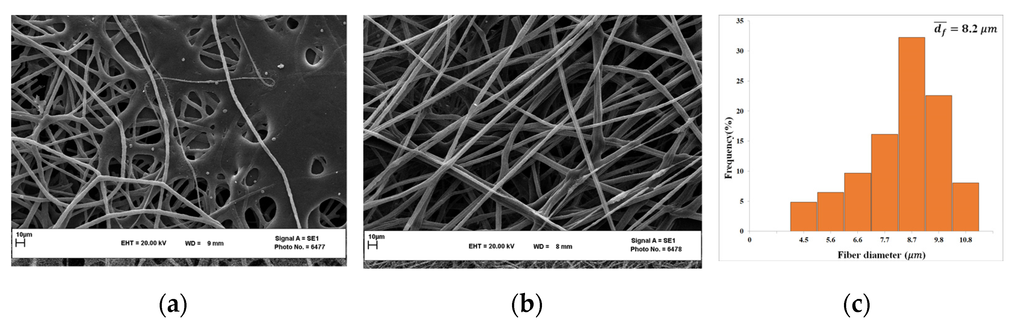
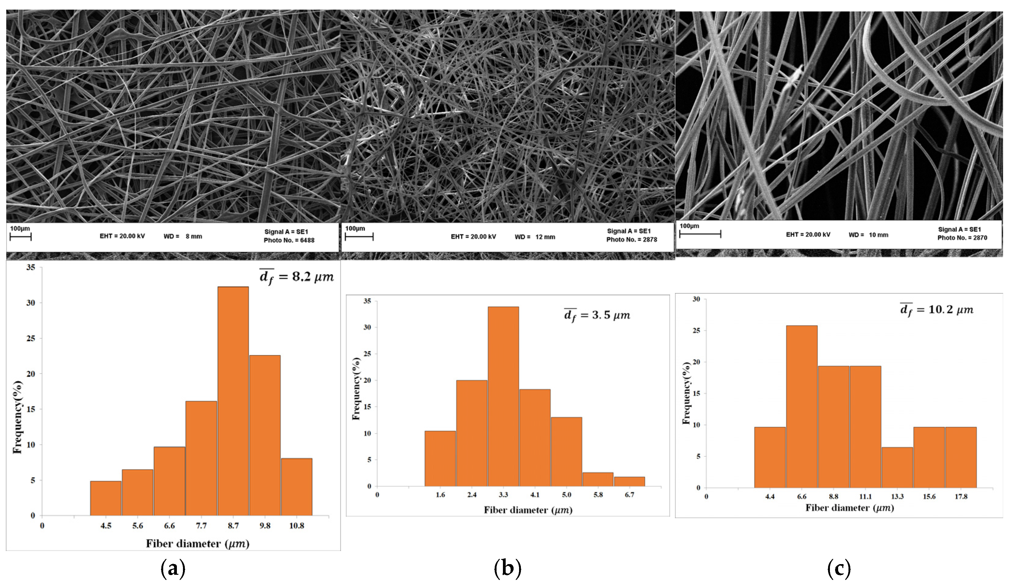
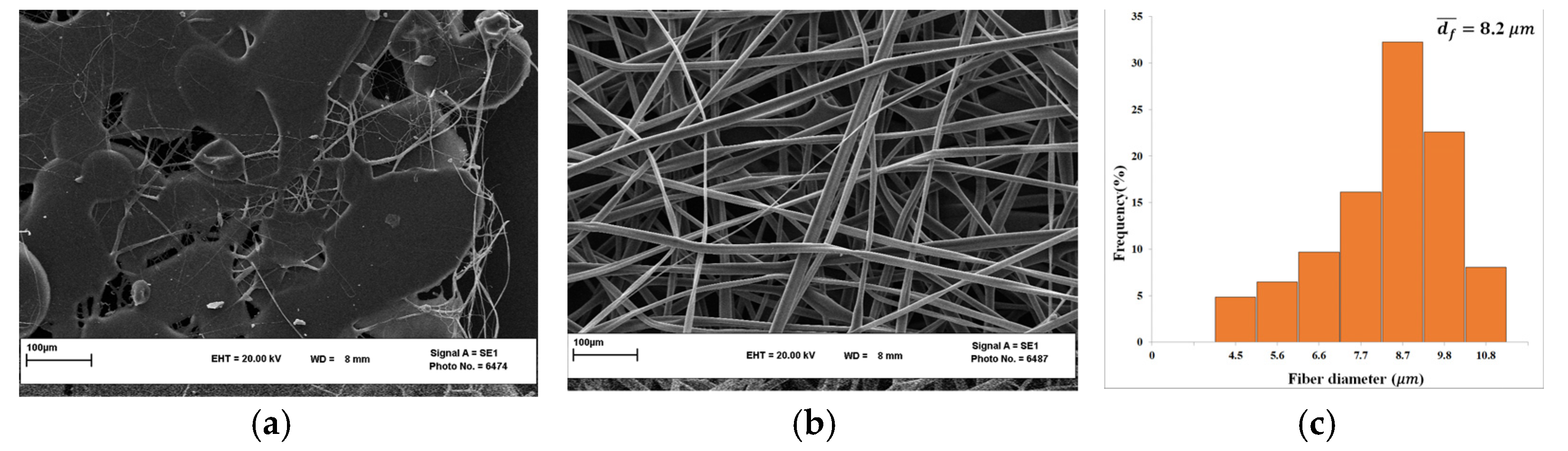
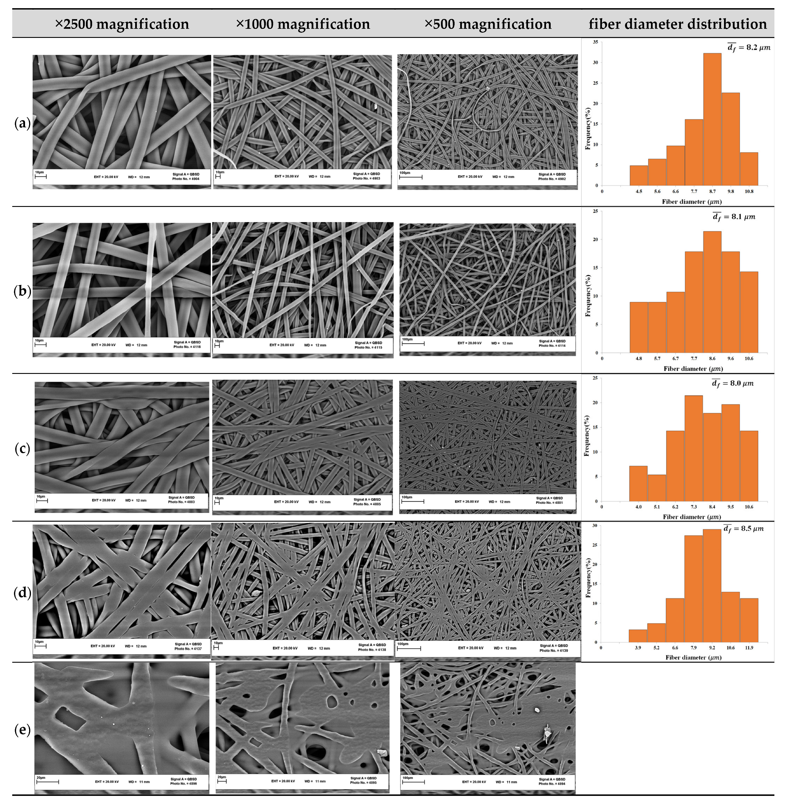
| Without post-treatment | 140 ± 20 | - | 8.2 ± 1.5 | 2.9 ± 2.3 | 10.0 ± 1.6 | 50 ± 20 |
| Cold-press | 92 ± 3 | 130.0 ± 2.3 | 8.1 ± 2.3 | 2.7 ± 1.4 | 9.1 ± 2.4 | 20 ± 4 |
| Hot-press (100 °C) | 81 ± 5 | 126.1 ± 1.5 | 8.0 ± 2.5 | 2.2 ± 0.5 | 7.1 ± 1.2 | 10 ± 2 |
| Hot-press (120 °C) | 80 ± 4 | 125.4 ± 1.7 | 8.5 ± 1.4 | 2.4 ± 0.9 | 7.3 ± 1.1 | 8.3 ± 1.4 |
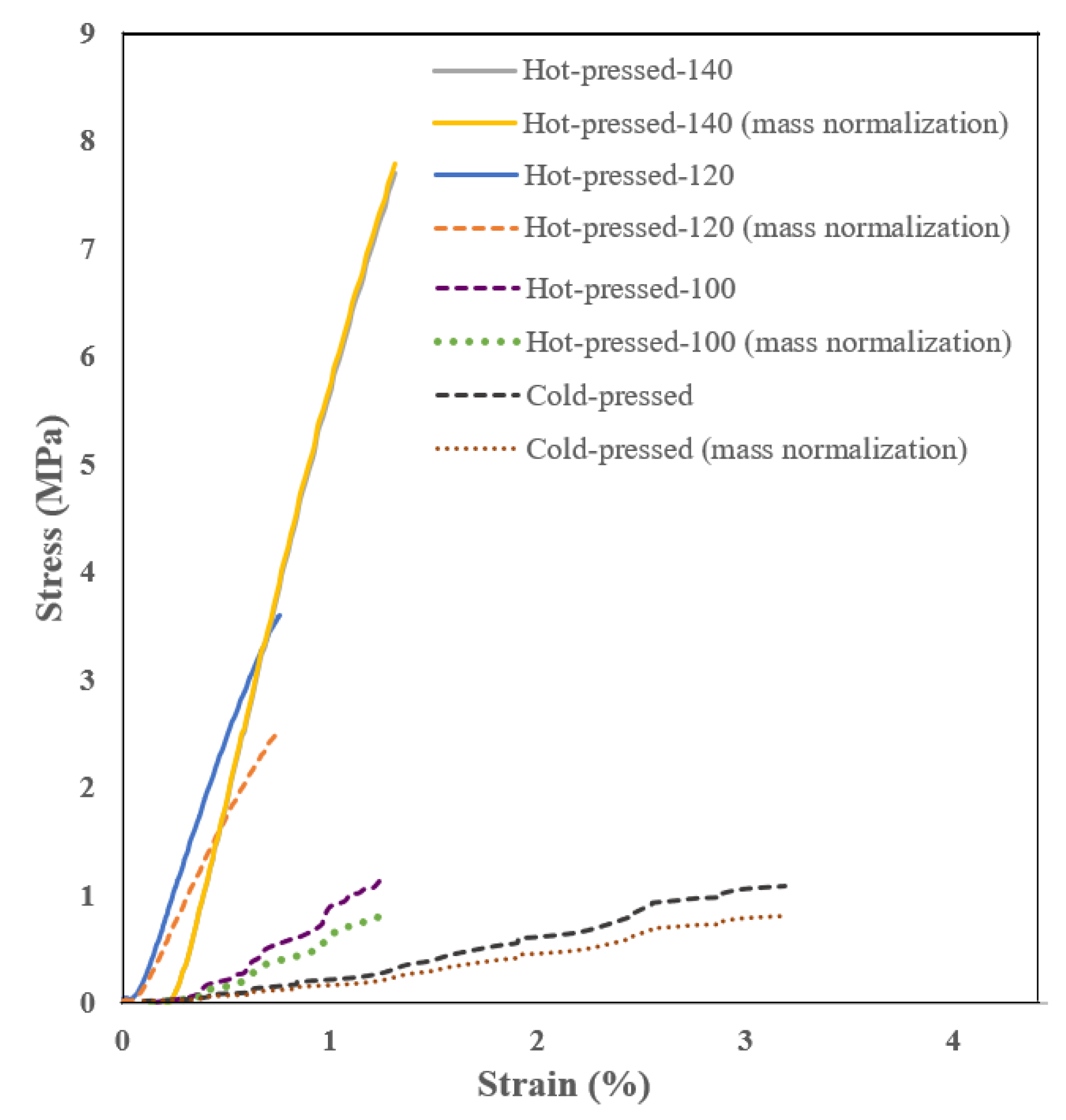
| Sample | Tensile Strength (MPa) | Elongation at Break (%) | Young’s Modulus (MPa) |
|---|---|---|---|
| Cold-press | 1.1 ± 0.6 | 70 ± 12 | 35.6 ± 4.2 |
| Hot-press (100 °C) | 1.4 ± 0.2 | 30 ± 8 | 103 ± 10 |
| Hot-press (120 °C) | 3.2 ± 0.4 | 1.5 ± 0.3 | 427 ± 14 |
| Hot-press (140 °C) | 6.8 ± 0.7 | 0.9 ± 0.5 | 575 ± 20 |
Disclaimer/Publisher’s Note: The statements, opinions and data contained in all publications are solely those of the individual author(s) and contributor(s) and not of MDPI and/or the editor(s). MDPI and/or the editor(s) disclaim responsibility for any injury to people or property resulting from any ideas, methods, instructions or products referred to in the content. |
© 2023 by the authors. Licensee MDPI, Basel, Switzerland. This article is an open access article distributed under the terms and conditions of the Creative Commons Attribution (CC BY) license (https://creativecommons.org/licenses/by/4.0/).
Share and Cite
Sabzekar, M.; Pourafshari Chenar, M.; Khayet, M.; García-Payo, C.; Mortazavi, S.M.; Golmohammadi, M. Development of Novel Electrospun Fibers Based on Cyclic Olefin Polymer. Nanomaterials 2023, 13, 2412. https://doi.org/10.3390/nano13172412
Sabzekar M, Pourafshari Chenar M, Khayet M, García-Payo C, Mortazavi SM, Golmohammadi M. Development of Novel Electrospun Fibers Based on Cyclic Olefin Polymer. Nanomaterials. 2023; 13(17):2412. https://doi.org/10.3390/nano13172412
Chicago/Turabian StyleSabzekar, Malihe, Mahdi Pourafshari Chenar, Mohamed Khayet, Carmen García-Payo, Seyed Mohammadmahdi Mortazavi, and Morteza Golmohammadi. 2023. "Development of Novel Electrospun Fibers Based on Cyclic Olefin Polymer" Nanomaterials 13, no. 17: 2412. https://doi.org/10.3390/nano13172412
APA StyleSabzekar, M., Pourafshari Chenar, M., Khayet, M., García-Payo, C., Mortazavi, S. M., & Golmohammadi, M. (2023). Development of Novel Electrospun Fibers Based on Cyclic Olefin Polymer. Nanomaterials, 13(17), 2412. https://doi.org/10.3390/nano13172412