Article

Lightweight Co3O4/CC Composites with High Microwave Absorption Performance

1
Hangzhou Dianzi University, Hangzhou 310018, China
2
Xiamen University, Xiamen 361005, China
3
National Engineering Laboratory for Textile Fiber Materials & Processing Technology, Zhejiang Sci-Tech University, Hangzhou 310018, China
*
Authors to whom correspondence should be addressed.
Nanomaterials 2023, 13(13), 1903; https://doi.org/10.3390/nano13131903
Submission received: 30 May 2023 / Revised: 15 June 2023 / Accepted: 20 June 2023 / Published: 21 June 2023

Abstract

:
With the rapid development of electronic and communication technology for military radars, the demand for microwave-absorbing materials in the low-frequency range with thin layers is growing. In this study, flexible Co3O4/CC (carbon cloth) composites derived from Co-MOFs (metal–organic frameworks) and CC are prepared using hydrothermal and thermal treatment processes. The flexible precursors of the Co-MOFs/CC samples are calcined with different calcination temperatures, for which the material structure, dielectric properties, and microwave absorption performance are changed. With the increases in calcination temperature, the minimum reflection loss of the corresponding Co3O4/CC composites gradually moves to the lower frequency with a thinner thickness. In addition, the Co3O4/CC composites with the 25 wt% filler loading ratio exhibit the minimum reflection loss (RL) of −46.59 dB at 6.24 GHz with a 4.2 mm thickness. When the thickness is 3.70 mm, the effective absorption bandwidth is 3.04 GHz from 5.84 to 8.88 GHz. This study not only proves that the Co3O4/CC composite is an outstanding microwave-absorbing material with better flexibility but also provides useful inspiration for research on wideband microwave absorption materials below 10 GHz.

1. Introduction

With the rapid development of science and technology, the influences of electromagnetic radiation on the human body and environment have attracted extensive attention. In terms of this background, the development of microwave absorption materials can help resist electromagnetic radiation and has become a research hotspot around the world [1]. An ideal microwave-absorbing material should have excellent properties such as a light weight, thin thickness, strong reflection, and broad effective absorption bandwidth [2]. In recent years, researchers have studied a variety of ideal microwave-absorbing materials including magnetic loss materials and dielectric loss materials. For instance, Wang et al. synthesized Fe3O4@SnO2/RGO ternary composites with an efficient and rapid three-step method, improving the impedance matching and obtaining excellent electromagnetic wave absorption performance [3]. Moreover, ZnO [4], Fe2O3/N-Graphene/CNTs [5], composite nonlinear feedback (CNF)/SiO2 [6], and MOF derivatives [7] have also been widely developed to improve the attenuation characteristics of electromagnetic waves. In view of the loss mechanism of electromagnetic waves, it is generally easier to achieve strong broadband microwave absorption at high frequencies. However, the absorbing materials at low frequencies are normally thick and have a narrow frequency bandwidth, making it difficult to meet the needs of practical applications. Therefore, it is essential to research lightweight, thinner layers with wide bandwidth absorbers below 10 GHz.
Among a large number of lightweight electromagnetic absorption materials, MOF derivatives have been extensively manufactured because of their variety of metals, diverse morphologies, and large surface areas [8,9,10,11]. For example, Ma et al. synthesized TiO2/C nanoporous carbon composites via the pyrolysis of MIL-125 (Ti-based MOFs), which exhibited a maximum reflection loss of −49.60 dB, with a thinner thickness of 1.6 mm and obtaining a 4.6 GHz effective absorption bandwidth [12]. In addition, Shi et al. studied the nanoporous Co3O4 nanosheets derived from Co-MOFs. When the matching thickness is 2.5 mm, the maximum reflection loss can reach −32 dB, and the effective absorption band width can reach 4.2 GHz because of its better impedance matching of the composites [13]. Additionally, Liu et al. also designed Co-MOF derivatives to improve the absorption performance at low frequencies. Better impedance matching was achieved with the Co/C composite, the minimum reflection loss value for which was about −20 dB, while the effective absorption bandwidth reached 3.84 GHz in the C-band frequency range [14]. Therefore, the MOF derivatives could obtain broadband absorption performances with thinner thicknesses at low frequencies. In addition, MOFs can be combined with other functional materials to improve the microwave absorption performance. For example, Yang et al. fabricated SiC/Ni/NiO/C by annealing SiC/Ni-MOFs nanoparticles, for which the minimal RL value reached −50.52 dB [15]. Furthermore, Fe/Fe3C/C derived from MIL-101-Fe and MIL-88-Fe was obtained by Miao et al. The minimum RL of the composites was −59.2 dB with a thickness of 4.32 mm, and the effective bandwidth reached 6.5 GHz at 2 mm [16]. Thus, the combination of MOF derivatives and another material is better for the loss of microwave absorption.
In recent decades, carbon cloth (CC) has been applied to various fields owing to its light weight, high strength, corrosion resistance, and aging resistance [17,18,19,20,21,22,23]. Luo et al. prepared NiSe2/CC as an electrode material without an adhesive, which showed good hydrogen evolution reaction performance and chemical stability in a 0.5 mol/LH2SO4 solution [24]. Zhan et al. grew porous arrays of CoP nanoparticles derived from MOFs on carbon cloth for effective alkaline hydrogen evolution [25]. Along with these studies, carbon cloth can also be used to prepare flexible microwave absorbers. Che et al. made ZnO grow on a CC flexible substrate, constructing a three-dimensional conductive network with multiple interfaces [26]. Moreover, Liu et al. grew Co-MOFs on a conductive CC and derived CC@NPC/CoS2 composites of RL reaching −59.6 dB at 2.8 mm [27]. Based on the above, the carbon cloth can be combined with metal–organic framework materials to prepare excellent electromagnetic wave absorbers with thin layers.
In this study, Co3O4/CC derived from Co-BTC-MOFs/CC (Co-MOFs/CC) was synthesized, with the results indicating that the absorbing properties of the Co3O4/CC composite can be adjusted by controlling the different calcination temperatures. When the calcination temperature was 500 °C, the Co3O4/CC composites showed an RLmin (minimum reflection loss) of −46.59 dB at 6.24 GHz, with a filler loading ratio of 25 wt%. Furthermore, the Co3O4/CC material exhibited an effective microwave absorption bandwidth of 3.04 GHz from 5.84 GHz to 8.88 GHz with a thickness of 3.70 mm. Thus, the Co3O4/CC composite derived from the metal–organic framework and CC can be seen as a promising wide-band absorbing material below 10 GHz with a thin layer.

2. Materials and Methods

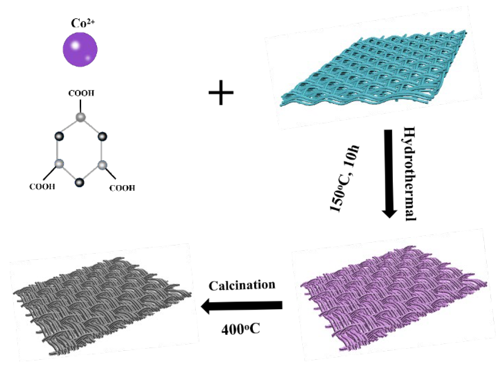
2.1. Preparation of the Co3O4/CC Precursor

A piece of 2 × 2 cm2 CC was placed in acetone for cleaning by deionized water and ethanol, which was ultrasonicated for 20 min and then dried in a vacuum oven at 60 °C for 6 h. The preparation of the Co-MOFs/CC occurred as in Figure 1, by dissolving 432 mg of cobalt nitrate hexahydrate, 300 mg of trimesic acid, and 3 g of PVP K30 (polyvinylpyrrolidone K30) in a 60 mL mixture solution (deionized water/DMF/ethanol =1:1:1 v/v/v) and stirring vigorously with a blender until completely dissolved. Then, we placed the cleaning CC into the bottom of a 100 mL Teflon autoclave and transferred the solution into it. Finally, the Teflon autoclave was heated in an oven at 150 °C for 10 h and the Co-MOFs/CC was obtained. The Co3O4/CC precursor was obtained after washing with deionized water and ethanol three times and drying in an oven at 60 °C for 12 h.

2.2. Synthesis of Co3O4/CC Composites

The Co-MOFs/CC composites were heated to 300 °C, 400 °C, and 500 °C, respectively, in a muffle furnace with a heating rate of 2 °C/min and heated for two hours to obtain multilayer Co3O4/CC composites, named as S1, S2, and S3, respectively.

2.3. Characterization and Measurement

The morphologies of the Co3O4/CC and pure CC were characterized by field emission scanning electron microscopy (FE-SEM, S-4800, Hitachi, Tokyo, Japan), and an X-ray diffractometer (XRD) was used to collect powder diffraction data in the range of 10–70 °C with Cu Kα radiation (λ = 1.5418 Å). The XPS data were obtained using a model Versa Probe (PHI 5000, Guangzhou, China). Then, the relative complex permittivity and permeability in the frequency range of 2–18 GHz were measured by the vector network analyzer (Agilent PNA N5224A, Keysight, Budd Lake, NJ, USA) with the coaxial method. The filler loading ratio of the testing ring was 25 wt%, and the inner and external diameters were 3.04 and 7.00 mm, respectively. The microwave absorption performance with reflection loss of the Co3O4/CC was calculated by the permittivity and permeability.

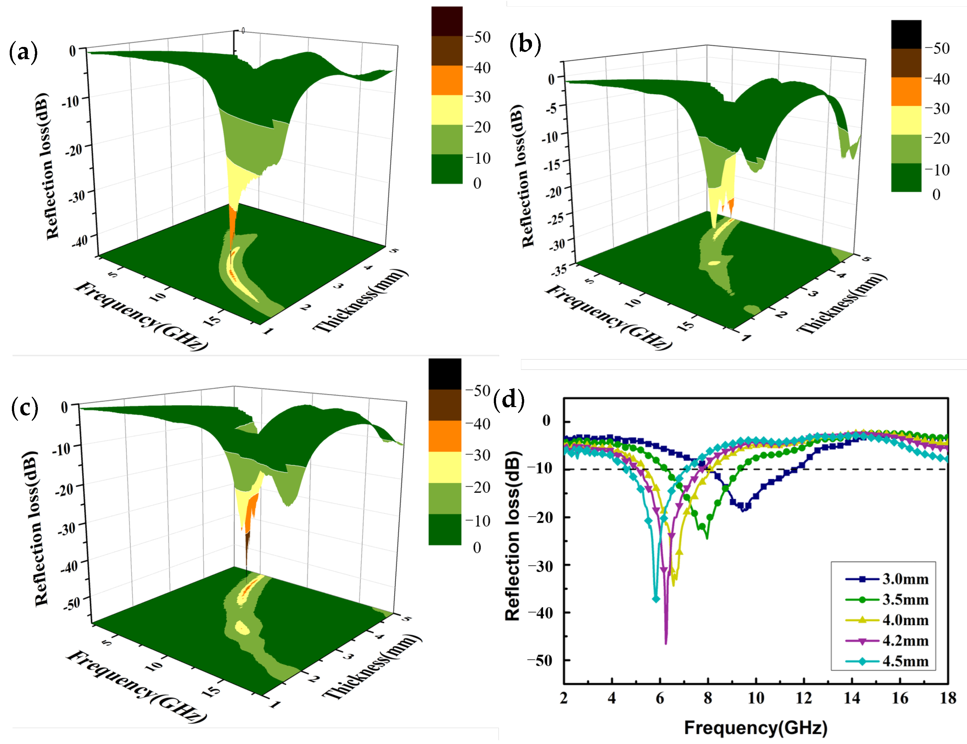
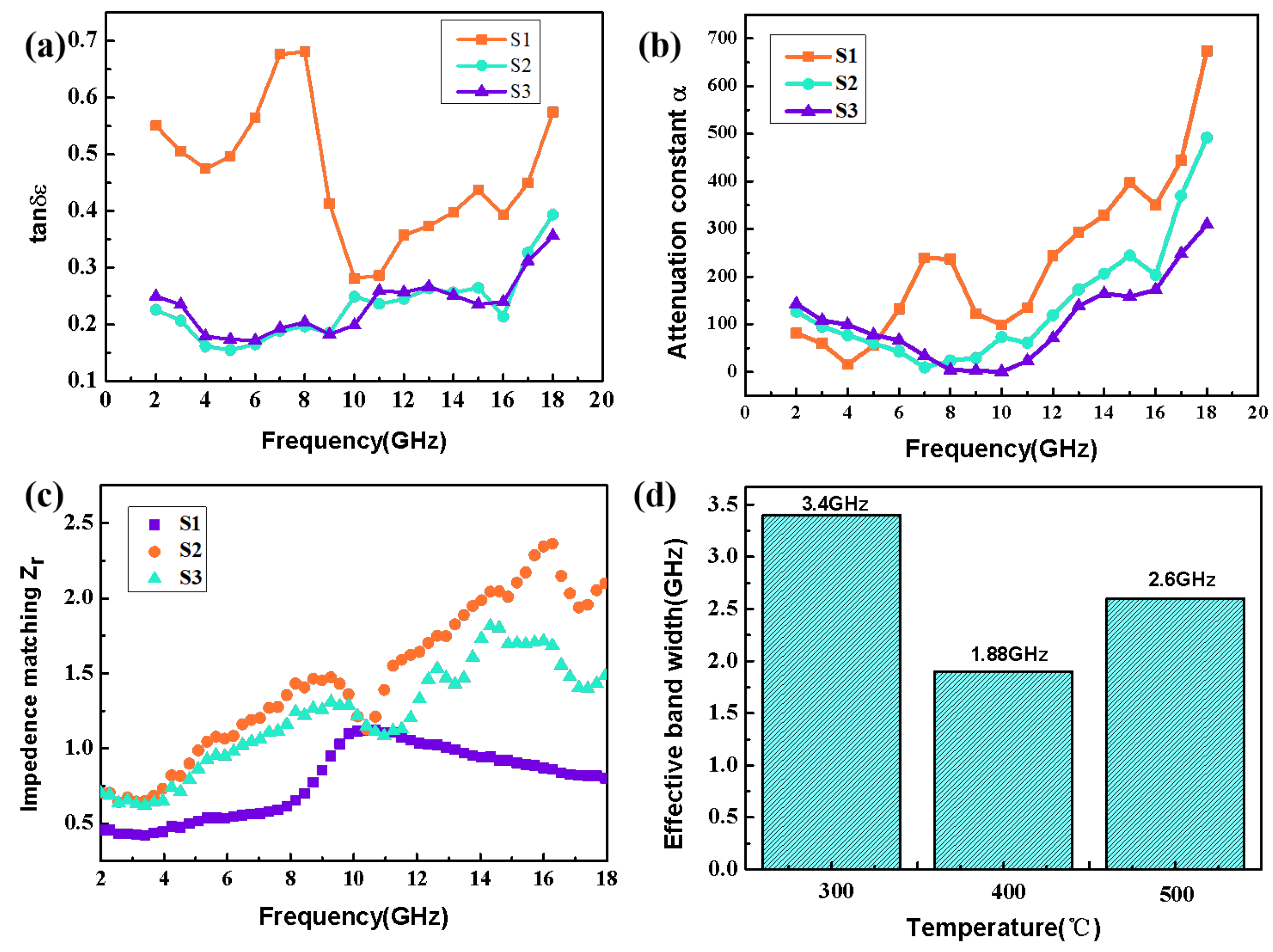
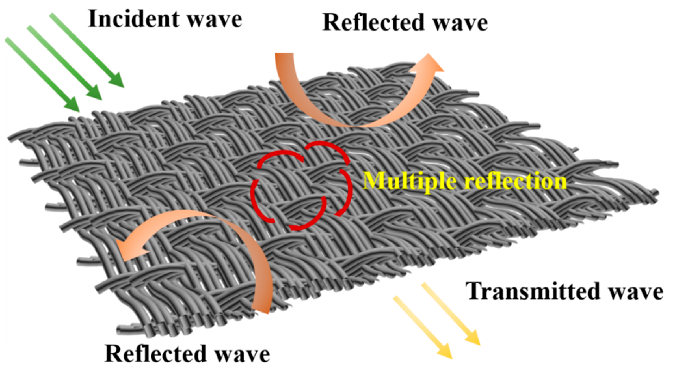
3. Results and Discussion

The sample phase composition and crystallinity of Co3O4/CC composites can be observed using an XRD diffraction analysis. In order to test the successful synthesis of the Co-MOFs and Co3O4/CC composites, we firstly studied the XRD patterns of the samples before and after calcination. Figure 2a is the XRD pattern of the Co-MOFs/CC, and obvious diffraction peaks can be observed at 12.73°, 19.21°, 28.70°, 32.32°, and 36.95°, which fully coincide with the locations of the Co-MOFs’ diffraction peaks [28,29]. This proves the successful synthesis of the precursor Co-MOFs. Figure 2b shows the XRD pattern of S1–S3 obtained from powder diffraction data processed by the X-ray diffractometer in the region of 10 °C to 70 °C. The diffraction peaks of Co3O4 can be observed at 31.27°, 36.85°, and 44.81° for S1–S3, corresponding to the (220), (311), and (400) lattice planes, respectively. In addition, obvious diffraction peaks of C can be observed at 22.76° (120), 26.57° (103), and 29.31° (113), which prove the existence of Co3O4 and carbon [30]. At the same time, no other impurity peaks can be observed, indicating that the sample has high purity and crystallinity [31]. It is obvious that Co3O4/CC was successfully synthesized.
The pictures of CC, Co-MOFs/CC, and Co3O4/CC are shown in Figure S1, showing that the Co3O4/CC kept the flexibility of the CC. The morphologies of Co3O4/CC composites with different temperatures were characterized by SEM pictures, which are shown in Figure 3. It can be seen from Figure 3 that the morphologies of the samples with the three different temperatures are very similar. The cross-arrangement of the cylindrical morphology is well maintained and the structure’s size is quite uniform, which is better for the reflection and scattering of electromagnetic waves, which could improve the microwave absorption performance. However, with increasing temperatures, the morphology of the Co3O4/CC becomes rough. In particularly, it can be seen from Figure 3f that most of the cylinder has been broken and presents a loose and porous structure, which may be caused by the collapse of the Co-MOFs. In addition, the surface of the CC is relatively smooth and a floccule appears in the broken CC, which demonstrates that the Co3O4 is grown inside of the CC. The floccule could provide a loose and porous structure, which can offer more contact sites and increase the attenuation of electromagnetic waves.
The valence states of elements in the composites can be clearly indicated by XPS [32]. The XPS results for the Co3O4/CC are shown in Figure 4. Figure 4a shows the wide spectrum of Co3O4/CC composite materials, while Figure 4b–d show the spectra of C 1s, O 1s, and Co 2p of the S3 composite, respectively. As can be seen from Figure 4b, two characteristic peaks appear in the C-1s spectrum of Co3O4/CC, which was peak-divided, with the C-C/C=C peak appearing at 284.6 eV and the C-O peak emerging at 286.7 eV. It is obvious that the C-C/C=C bond signal is the strongest, which indicates that most of the Co3O4/CC precursor has become amorphous carbon after calcination and carbonization [33]. The results of the XPS analysis in Figure 4c show that two characteristic peaks also appear in the O 1s spectrum of Co3O4/CC, in which the peaks loading at 531.6 eV and 532.5 eV are the chemisorbed oxygen and the lattice O of Co3O4. In Figure 4d, the spectral peaks of Co 2P at 781.0 eV and 797.1 eV belong to Co 2P 3/2 and Co 2P 1/2, respectively [34]. The characteristic peaks can be attributed to cobalt nitrate hexahydrate and also indicate the presence of C and O elements.
After calcination of the Co3O4/CC precursor at different temperatures, the internal structure of the Co3O4/CC composite will be changed, which will affect the dielectric constant and magnetic permeability of the composite and adjust its microwave absorption properties. In this study, we only pay attention to the dielectric characteristic analysis on account of the weak magnetism of the generated Co3O4/CC complex. The real parts (ε′) and imaginary parts (ε″) of the complex dielectric constant represent the dielectric storage and dielectric loss capacity of the material, respectively [35]. It can be revealed from Figure 5 that the ε′ of the Co3O4/CC complex generally decreases with the increase in frequency. It is worth noting that the ε′ increases several times after the high frequency part at 9 GHz, which is mainly from exchange resonance [36]. According to Debye’s theory, the real and imaginary parts of the complex dielectric constant can be expressed in the following forms [37]:
ε = ε + ( ε s ε ) / ( 1 + ω 2 τ 2 )
ε = ( ε s ε ) ω τ / ( 1 + ω 2 τ 2 ) + σ ac / ω ε 0
where εs represents the static permittivity, ε is the infinite static permittivity, ω is the angular frequency, τ is the polarization relaxation time, σac is the electrical conductivity, and ε0 represents the vacuum permittivity. According to Equation (1), the real part of the dielectric constant of the generated complex decreases due to the increase in angular frequency, which reveals the dispersion effect of the complex in favor of microwave absorption. The essence of this phenomenon is from the existence of polarization relaxation below this frequency. Moreover, the peak value of the imaginary part of the dielectric constant (ε″) belongs to the dielectric polarization peak, which is conducive to increasing the dielectric polarization loss. In fact, ε″ is an expression of the material’s electrical conductivity, based on Debye’s theory, which can be expressed by using the following formula [37]:
ε σ 2 π ε 0 f
where σ is the electrical conductivity and ε 0   is the dielectric constant in a vacuum. According to Formula (3), the decrease in conductivity leads to a lower ε″, which indicates that the complex S3 has lower electrical conductivity than S1 and S2. This is because more and more Co3O4 is generated as the temperature increases, resulting in an increase in the resistivity of the material. From Figure 5b, it can be seen that the ε″ order of the complex at the three temperatures is roughly S1 > S2 > S3, indicating that except for the polarization relaxation phenomenon, there are conductivity losses due to the migration of free carriers in the CC.
After analyzing the complex permittivity of the Co3O4/CC composite, the reflection loss of the generated composite was analyzed. Figure 6 shows a three-dimensional image of the RLs with different calcination temperatures and matching thicknesses, where one can directly observe the RL value of the Co3O4/CC composite. The calculation formulas for the RL of the electromagnetic wave are as follows:
Z i n = Z 0 ( μ r / ε r ) 1 / 2 tan   h [ j ( 2 π f d / c )   ( ε r μ r ) 1 / 2 ]
R L = 20 log ( Z i n Z 0 ) / ( Z i n + Z 0 )
where Z0 represents the impedance value of the free space. Figure 6a shows the three-dimensional (3D) RL of S1, and it can be seen that the minimum RL is −44.68 dB at 11.72 GHz with a thickness of 2.10 mm. Although the matching thickness of S1 is relatively thin, the frequency corresponding to the minimum reflection loss is still in the high-frequency range (Ku band). The minimum reflection loss of S2 in Figure 6b is −33.95 dB, and the corresponding frequency and thickness are 5.4 GHz and 4.90 mm. The RL value of S3 is shown in Figure 6c, and the minimum RL can reach −46.59 dB at 6.24 GHz with a 4.2 mm thickness. It can be concluded that the frequency of the minimum RL gradually moves to low frequencies with the increase in calcination temperature. According to Figure 6a, the RL value is less than −10 dB in the frequency range of 10.76 to 14.16 GHz for S1; thus, the effective absorption band width of S1 is 3.4 GHz. Similarly, S2 (Figure 6b) has an effective absorption band width of 1.88 GHz in the frequency range of 4.52~6.4 GHz, while S3 (Figure 6d) has an effective absorption band width of 2.6 GHz with a frequency range of 5.12~7.72 GHz. It is well known that a good electromagnetic wave absorber should have good attenuation ability, superior impedance matching performance, a minimal RL value, a wide effective absorption band width, and so on [38,39]. According to the above analysis, it is obvious that S3 shows better reflection loss and a thinner matching thickness in the frequency region of less than 6 GHz. Therefore, the manufacture of Co3O4/CC complexes at a calcination temperature of 500 °C is suitable for microwave-absorbing materials in the low-frequency range.
In order to further explore the reason why the Co3O4/CC composites have different absorbing properties with different calcination temperatures, the dielectric loss, attenuation ability for electromagnetic waves, and impedance matching of the composites were further analyzed in this study. The dielectric loss is usually presented by the loss tangent of permittivity, with a higher loss tangent indicating better dielectric loss. The loss tangent of permittivity can be expressed in the following formula [40]:
tan δ ε = ε / ε
Figure 7a presents the variations in dielectric loss of the Co3O4/CC composites with different calcination temperatures. In general, the tan δε values at three temperatures demonstrate an upward trend in terms of the increase in frequency. Additionally, a few relaxation peaks appear at low frequencies, which proves that polarization relaxation occurs in the low-frequency range, indicating better microwave absorption. Regarding samples S1–S3, the S1 composite has higher dielectric loss.
In addition to the dielectric loss, the attenuation factor α [41] and impedance matching Zr [42] also play vital roles in the electromagnetic wave absorption performance. Attenuation α refers to the amplitude or power attenuation in the electromagnetic wave transmission process, which is related to the dielectric loss. As can be seen from Figure 7b, the magnitude relationship of the attenuation ability of the three samples is αS1 > αS2 > αS3, indicating that sample S1 has better attenuation ability for electromagnetic waves. This is because with the enhanced calcination temperature, the amount of Co3O4 generated gradually increases, leading to a decrease in permittivity. This phenomenon will bring about decreased dielectric loss and attenuation loss, illustrating that the decrease in attenuation α is connected with the increase in calcination temperatures. For electromagnetic absorbents, an outstanding absorbing material should consider not only the strong electromagnetic propagation loss but also the impedance matching. The attenuation constant α and impedance matching Zr can be described in the following formulas:
α = 2 π f c ( μ ε μ ε ) + ( μ ε μ ε ) 2 + ( μ ε + μ ε ) 2
Z r = Z in / Z 0
where Zr represents the impedance matching value, Z0 is the free-space impedance value, Zin represents the incident impedance matching value, and c represents the speed of light. When Zr = 1, the electromagnetic wave can achieve zero reflection on the absorber surface; that is, the absorption effect reaches the best value and the condition of εr = μr should be satisfied. According to Figure 7c, the frequency corresponding to the minimum reflection loss of S1 is 11.72 GHz, and the corresponding impedance match at this frequency is 1.06. Similarly, the impedance values matching corresponding values of S2 and S3 are 0.53 and 1.00 with the minimum reflection loss, respectively. In addition, the impedance matching values of S3 are closer to 1 at 6–8 GHz. Therefore, this illustrates that S3 achieved almost perfect impedance matching at low frequencies. On the basis of this result, S3 shows better electromagnetic wave absorption performance and attenuation ability at low frequencies. Additionally, as shown in Figure 7d, S1 has the better effective broadband absorption bandwidth of the composites with the three different calcination temperatures.
Therefore, S3 shows excellent microwave absorption performance below 10 GHz, and the minimum reflection loss and effective band absorption width of S3 are further analyzed in this paper. Figure 8a,b show the minimum RL values of S3 with different matching thicknesses. When the thickness is 4.2 mm, the minimum reflection loss at 6.24 GHz is −46.59 dB, indicating elegant electromagnetic wave absorption characteristics. When the thickness of S3 is reduced to 3.7 mm, the maximum effective absorption bandwidth is 3.04 GHz from 5.84 GHz to 8.88 GHz, and at that moment the minimum reflection loss is −32.13 dB. Compared with the previous work that is reported in Table 1, the Co3O4/CC composites have a thinner matching thickness and stronger reflection loss below 10 GHz.
Based on the above, the Co3O4/CC composites have better microwave absorption properties with thinner thicknesses and have widely effective absorption bandwidths below 10 GHz. The possible mechanisms of the microwave absorption are as shown in Figure 9. Firstly, the carbon cloth and Co3O4 together cause losses of incident electromagnetic waves. Secondly, the carbon cloth could provide the network structure that allows more incident waves to enter into the internal section. Finally, when the incident wave passes into the network structure, the Co3O4 and CC could consume it and generate dielectric loss. Therefore, the CC and Co3O4 synergistically improve the microwave absorption.

4. Conclusions

In summary, the Co3O4/CC precursor was synthesized using the simple hydrothermal method and the Co3O4/CC derivatives were generated at different calcination temperatures. It was concluded that with the increases in calcination temperature, the electromagnetic wave absorption performance was improved gradually in the low-frequency range. When the calcination temperature was 500 °C, the minimum reflection loss RL reached −46.59 dB at 6.24 GHz with a 4.2 mm thickness. When the thickness was 3.7 mm, the effective absorption band width was 3.04 GHz in the C band and the minimum reflection loss was −32.13 dB. The synergistic effect of CC and Co3O4 resulted in better microwave absorption performance with a thinner thickness and widely effective bandwidth below 10 GHz. This provides useful inspiration for the growth of absorbing materials on carbon cloth at low frequencies, which is worthy of further investigation.

Supplementary Materials

The following supporting information can be downloaded at: https://www.mdpi.com/article/10.3390/nano13131903/s1, Figure S1: Photos of pure carbon cloth (a); photograph of dried CC covered with precursors (b); Photograph of CC covered with compound Co3O4/CC after calcination (c).

Author Contributions

Conceptualization, B.A. and X.L.; data curation, B.A.; formal analysis, B.A. and X.Y.; investigation, B.A., M.W. and X.L.; supervision, X.L. and C.F.; validation, X.L. and C.F.; visualization, B.A.; writing—original draft, B.A.; writing—review and editing, X.L., Z.M. and C.F. All authors have read and agreed to the published version of the manuscript.

Funding

This work was supported by the National Natural Science Foundation of China (Grant No. 52101218), the Zhejiang Provincial Natural Science Foundation of China (Grant No. LQ22E010004), the Fundamental Research Funds for the Provincial Universities of Zhejiang (Grant No. GK219909299001-009), the National Key R&D Program of China (Grant No. 2022YFB3504804), the National Key R&D Program of China (Grant No. 2021YFA1600203), and the Ten Thousand Talents Plan of Zhejiang Province of China (Grant No. 2019R52014).

Data Availability Statement

The data that support the findings of this study are available from the corresponding authors upon reasonable request.

Acknowledgments

Thanks to everyone who helped with this work.

Conflicts of Interest

The authors declare no conflict of interest.

References

  1. Zhang, Z.; Wang, F.; Zhang, X.; Li, W.; Guan, G. Research progress of low frequency wideband thin layer absorbing materials. J. Funct. Mater. 2019, 50, 606038–606045. [Google Scholar]
  2. Wu, F.; Xie, A.; Sun, M.; Wang, Y.; Wang, M. Reduced graphene oxide (RGO) modified spongelike polypyrrole (PPy) aerogel for excellent electromagnetic absorption. J. Mater. Chem. 2015, 3, 14358–14369. [Google Scholar] [CrossRef]
  3. Wang, Y.; Peng, Z.; Jiang, W. Controlled synthesis of Fe3O4@SnO2/RGO nanocomposite for microwave absorption enhancement. Ceram. Int. 2016, 42, 10682–10689. [Google Scholar] [CrossRef]
  4. Wang, G.; Wu, Y.; Zhang, X.; Li, Y.; Guo, L.; Cao, M. Controllable synthesis of uniform ZnO nanorods and their enhanced dielectric and absorption properties. J. Mater. Chem. 2014, A2, 8644–8651. [Google Scholar] [CrossRef]
  5. Zhou, N.; An, D.; Xiao, Z.; Zhai, S.; Shi, Z. Solvothermal synthesis of three-dimensional, Fe2O3 NPs-embedded CNT/N-doped graphene composites with excellent microwave absorption performance. RSC Adv. 2017, 7, 45156–45169. [Google Scholar] [CrossRef] [Green Version]
  6. Cao, M.; Song, W.; Hou, Z.; Wen, B.; Yuan, J. The effects of temperature and frequency on the dielectric properties, electromagnetic interference shielding and microwave-absorption of short carbon fiber/silica composites. Carbon 2010, 48, 788–796. [Google Scholar] [CrossRef]
  7. Yilmaz, G.; Yam, K.M.; Zhang, C.; Fan, H.J.; Ho, G.W. In situ transformation of MOFs into layered double hydroxide embedded metal sulfides for improved electrocatalytic and supercapacitive performance. Adv. Mater. 2017, 29, 1606814. [Google Scholar] [CrossRef] [PubMed]
  8. Qian, J.; Li, T.; Hu, Y.; Huang, S. A bimetallic carbide derived from a MOF precursor for increasing electrocatalytic oxygen evolution activity. Chem. Commun. 2017, 53, 13027–13030. [Google Scholar] [CrossRef] [PubMed]
  9. Liang, X.; Quan, B.; Sun, W.; Ji, G.; Zhang, Y.; Ma, J.; Li, D.; Zhang, B.; Du, Y. Multiple interfaces structure derived from metal–organic frameworks for excellent electromagnetic wave absorption. Part. Part. Syst. Charact. 2017, 34, 1700006. [Google Scholar] [CrossRef]
  10. Yin, Y.; Liu, X.; Wei, X.; Yu, R.; Shui, J. Porous CNTs/Co composite derived from zeolitic imidazolate framework: A lightweight, ultrathin, and highly efficient electromagnetic wave absorber. ACS Appl. Mater. Interfaces 2016, 8, 34686–34698. [Google Scholar] [CrossRef]
  11. Liu, W.; Shao, Q.; Ji, G.; Liang, X.; Cheng, Y.; Quan, B.; Du, Y. Metal–Organic frameworks derived porous carbon-wrapped Ni composites with optimized impedance matching as excellent lightweight electromagnetic wave absorber. Chem. Eng. J. 2017, 313, 734–744. [Google Scholar] [CrossRef]
  12. Ma, J.; Liu, W.; Liang, X. Nonporous TiO2/C composites synthesized from directly pyrolysis of a Ti-based MOFs MIL-125(Ti) for efficient microwave absorption. J. Alloys Compd. 2017, 728, 138–144. [Google Scholar] [CrossRef]
  13. Shi, F.; Hu, Y.; Wang, X. Decomposition of MOFs for the preparation of nano porous Co3O4 fibers and sheets with excellent microwave absorption and photocatalytic properties. Dalton Trans. 2017, 46, 1936–1942. [Google Scholar] [CrossRef]
  14. Liu, W.; Tan, S.; Yang, Z.; Ji, G. Enhanced low-grequency electromagnetic properties of MOF-derived cobalt through interface design. ACS Appl. Mater. Interfaces 2018, 37, 31610–31622. [Google Scholar] [CrossRef]
  15. Yang, R.; Yuan, J.; Yu, C.; Yan, K.; Fu, Y.; Xie, H.; Chen, J.; Chu, P.; Wu, X. Efficient electromagnetic wave absorption by SiC/Ni/NiO/C nanocomposites. J. Alloys Compd. 2020, 816, 152519. [Google Scholar] [CrossRef]
  16. Miao, P.; Zhou, R.; Chen, K.; Liang, J.; Ban, Q.; Kong, J. Tunable electromagnetic wave absorption of supramolecular isomer-derived nanocomposites with different morphology. Adv. Mater. Interfaces 2020, 7, 1901820. [Google Scholar] [CrossRef]
  17. Zhang, Q.; Song, Y.; Guo, J.; Wu, S.; Chen, N.; Fan, H.; Gao, M.; Yang, J.; Sheng, Z.; Lang, J. One-step hydrothermal synthesis of the modified carbon cloth membrane: Towards visible light driven and self-cleaning for efficient oil-water separation. Surf. Coat. Technol. 2021, 409, 126879. [Google Scholar] [CrossRef]
  18. Yang, L.; Chen, W.; Sheng, C.; Wu, H.; Mao, N.; Zhang, H. Fe/N-codoped carbocatalysts loaded on carbon cloth (CC) for activating peroxymonosulfate (PMS) to degrade methyl orange dyes. Appl. Surf. Sci. 2021, 549, 149300. [Google Scholar] [CrossRef]
  19. Sui, S.; Sha, J.; Deng, X.; Zhu, S.; Ma, L.; He, C.; Liu, E.; He, F.; Shi, C.; Zhao, N. Boosting the charge transfer efficiency of metal oxides/carbon nanotubes composites through interfaces control. J. Power Sources 2021, 489, 229501. [Google Scholar] [CrossRef]
  20. Xie, L.; Chen, S.; Hu, Y.; Lan, Y.; Li, X.; Deng, Q.; Wang, J.; Zeng, Z.; Deng, S. Construction of phosphatized cobalt nickel-LDH nanosheet arrays as binder-free electrode for high-performance battery-like supercapacitor device. J. Alloys Compd. 2021, 858, 157652. [Google Scholar] [CrossRef]
  21. Nie, Z.; Zhang, H.; Lu, Y.; Han, C.; Du, Y.; Sun, Z.; Yan, Y.; Yu, H.; Zhang, X.; Zhu, J. Manipulation of porosity and electrochemical artificial separator interphase for durable lithium-sulfur batteries. Chem. Eng. J. 2021, 409, 128137. [Google Scholar] [CrossRef]
  22. Liu, Z.; Ye, D.; Zhu, X.; Wang, S.; Chen, E.; Yang, Y.; Liao, Q. A self-pumping microfluidic fuel cell powered by formatted with Pd coated carbon cloth electrodes. J. Power Sources 2021, 490, 229553. [Google Scholar] [CrossRef]
  23. Dai, K.; Zhang, N.; Zhang, L.; Yin, L.; Zhao, Y.; Zhang, B. Self-supported Co/CoO anchored on N-doped carbon composite as bifunctional electrocatalyst for efficient overall water splitting. Chem. Eng. J. 2021, 414, 128804. [Google Scholar] [CrossRef]
  24. Luo, X.; Zhang, J.; Ci, C.; Bai, R.; Shi, D.; Xia, K.; Wu, D. Preparation of NiSe2/CC composite and its electrocatalytic performance for hydrogen evolution. Micro/Nano. Electron. Technol. 2021, 58, 207–213. [Google Scholar]
  25. Zhan, J.; Cao, X.; Zhou, J.; Xu, G.; Lei, B.; Wu, M. Porous array with CoP nanoparticle modification derived from MOF grown on carbon cloth for effective alkaline hydrogen evolution. Chem. Eng. J. 2021, 416, 128943. [Google Scholar] [CrossRef]
  26. Wang, L.; Li, X.; Li, Q.; Yu, X.; Zhao, Y.; Zhang, J.; Wang, M.; Che, R. Oriented polarization tuning broadband absorption from flexible hierarchical ZnO arrays vertically supported on carbon cloth. Small 2019, 15, 1900900. [Google Scholar] [CrossRef]
  27. Liu, P.; Zhu, C.; Gao, S.; Guan, C.; Huang, Y.; He, W. N-doped porous carbon nanoplates embedded with CoS2 vertically anchored on carbon cloths for flexible and ultrahigh microwave absorption. Carbon 2020, 163, 348–359. [Google Scholar] [CrossRef]
  28. Chen, N.; Chen, D.; Wei, F.; Zhao, S.; Luo, Y. Effect of structures on the adsorption performance of cobalt metal organic framework obtained by microwave-assisted ball milling. Chem. Phys. Lett. 2018, 705, 23–30. [Google Scholar] [CrossRef]
  29. Davydovskaya, P.; Pentyala, V.; Yurchenko, O.; Hussein, L.; Pohle, R.; Urban, G. Work function based sensing of alkanes and alcohols with benzene tricarboxylate linked metal organic frameworks. Sen. Actuat. B Chem. 2014, 193, 911–917. [Google Scholar] [CrossRef]
  30. Wan, G.; Wang, G.; Huang, X.; Zhao, H.; Li, X.; Wang, K.; Yu, L.; Peng, X.; Qin, Y. Uniform Fe3O4 coating on flower-like ZnO nanostructures by atomic layer deposition for electromagnetic wave absorption. Dalton Trans. 2015, 44, 18804–18809. [Google Scholar] [CrossRef]
  31. Wu, L.; Wang, Z.; Long, Y. Multishelled NixCo3-xO4 hollow microspheres derived from bimetal-organic frameworks as anode materials for high-performance lithium-ion batteries. Small 2017, 13, 1604270. [Google Scholar] [CrossRef] [PubMed]
  32. Zhu, Y.; Yu, T.; Sow, C.; Liu, Y.; Wee, A.; Xu, X.; Lim, C.; Thong, J. Efficient field emission from α-Fe2O3 nanoflakes on an atomic force microscope tip. Appl. Phys. Lett. 2005, 87, 023103. [Google Scholar] [CrossRef]
  33. Feng, W.; Wang, Y.; Chen, J.; Wang, L.; Guo, L.; Yang, J.; Jia, D.; Zhou, Y. Reduced graphene oxide decorated with in-situ growing ZnO nanocrystals: Facile synthesis and enhanced microwave absorption properties. Carbon 2016, 108, 52–60. [Google Scholar] [CrossRef]
  34. Yan, J.; Huang, Y.; Zhang, Z.; Liu, X. Novel 3D micro sheets contain cobalt particles and numerous interlaced carbon nanotubes for high-performance electromagnetic wave absorption. J. Alloys Compd. 2019, 785, 1206–1214. [Google Scholar] [CrossRef]
  35. Liang, X.; Zhang, X.; Liu, W.; Tang, D.; Zhang, B.; Ji, G. A simple hydrothermal process to grow MoS2 nanosheets with excellent dielectric loss and microwave absorption performance. J. Mater. Chem. C 2016, 4, 6816–6821. [Google Scholar] [CrossRef]
  36. Cui, X.; Liang, X.; Liu, W.; Gu, W.; Ji, G.; Du, Y. Stable microwave absorber derived from 1D customized heterogeneous structures of Fe3N@C. Chem. Eng. J. 2020, 381, 122589. [Google Scholar] [CrossRef]
  37. Liang, X.; Quan, B.; Ji, G.; Liu, W.; Cheng, Y.; Zhang, B.; Du, Y. Novel nanoporous carbon derived from metal-organic frameworks with tunable electromagnetic wave absorption capabilities. Inorg. Chem. Front. 2016, 3, 1516–1526. [Google Scholar] [CrossRef]
  38. Cao, M.; Qin, R.; Qiu, C.; Zhu, J. Matching design and mismatching analysis towards radar absorbing coatings based on conducting plate. Mater. Eng. 2003, 24, 391–396. [Google Scholar] [CrossRef]
  39. Song, W.; Cao, M.; Hou, Z.; Yuan, J. High-temperature microwave absorption and evolutionary behavior of multiwalled carbon nanotube nanocomposite. Scr. Mater. 2009, 61, 201–204. [Google Scholar] [CrossRef]
  40. Wang, L.; Jia, X.; Li, Y.; Yang, F.; Zhang, L.; Liu, L.; Ren, X.; Yang, H. Synthesis and microwave absorption property of flexible magnetic film based on graphene oxide/carbon nanotubes and Fe3O4 nanoparticles. J. Mater. Chem. A 2014, 2, 14940–14946. [Google Scholar] [CrossRef]
  41. Lv, H.; Ji, G.; Liang, X.; Zhang, H.; Hai, Q.; Du, Y. A novel rod-like MnO2@Fe loading on graphene giving excellent electromagnetic absorption properties. J. Mater. Chem. C 2015, 3, 5056–5064. [Google Scholar] [CrossRef]
  42. Zhang, X.; Ji, G.; Liu, W.; Quan, B.; Liang, X.; Shang, C.; Cheng, Y.; Du, Y. Thermal conversion of an Fe3O4@metal-organic framework: A new method for an efficient Fe-Co/nanoporous carbon microwave absorbing material. Nanoscale 2015, 7, 12932–12942. [Google Scholar] [CrossRef]
Figure 1. A structure diagram of the experimental process.
Nanomaterials 13 01903 g001
Figure 2. XRD pattern of Co-MOFs (a) and the XRD patterns of S1–S3 (b).
Nanomaterials 13 01903 g002
Figure 3. SEM images of (a,b) S1, (c,d) S2, and (e,f) S3.
Nanomaterials 13 01903 g003
Figure 4. (a) XPS survey spectrum of S3. (b) C 1s, (c) O 1s, and (d) Co 2p from the core-level spectrum in S3. (Different colors represent different peak positions).
Nanomaterials 13 01903 g004
Figure 5. The permittivity of the real (a) and imaginary (b) parts of the Co3O4/CC complex at three temperatures.
Nanomaterials 13 01903 g005
Figure 6. The 3D plots of RL values for Co3O4/CC samples with different calcination temperatures of (a) S1, (b) S2, and (c) S3 in the frequency range of 2–18 GHz. (d) The RL values of S3 with different thicknesses.
Nanomaterials 13 01903 g006
Figure 7. Frequency dependence rates of (a) tan δε, (b) α, and (c) Zr for S1–S3. (d) Effective absorption bandwidths with three calcination temperatures.
Nanomaterials 13 01903 g007
Figure 8. RL curves of S3 at thicknesses of (a) 4.2 mm and (b) 3.7 mm.
Nanomaterials 13 01903 g008
Figure 9. Diagram of the microwave attenuation mechanism for Co3O4/CC composites.
Nanomaterials 13 01903 g009
Table 1. Microwave absorption performances of the similar materials.
FillerRL (dB)Thickness (mm)Effective Bandwidth (GHz)Ref.
(Zn0.8Mn0.2)2Y and Co2Z department hexagonal ferrite−15>53.2[40]
NiZn Spinel type ferrite−10 120.7[41]
Magnesium doped barium ferrite−106.03[13]
Mg doped lithium zinc ferrite−395.56.5[13]
Co3O4/CC−46.594.23.04This work
Disclaimer/Publisher’s Note: The statements, opinions and data contained in all publications are solely those of the individual author(s) and contributor(s) and not of MDPI and/or the editor(s). MDPI and/or the editor(s) disclaim responsibility for any injury to people or property resulting from any ideas, methods, instructions or products referred to in the content.

