Abstract
In this paper, we present a theoretical study of electronic transport in planar Josephson Superconductor–Normal Metal–Superconductor (SN-N-NS) bridges with arbitrary transparency of the SN interfaces. We formulate and solve the two-dimensional problem of finding the spatial distribution of the supercurrent in the SN electrodes. This allows us to determine the scale of the weak coupling region in the SN-N-NS bridges, i.e., to describe this structure as a serial connection between the Josephson contact and the linear inductance of the current-carrying electrodes. We show that the presence of a two-dimensional spatial current distribution in the SN electrodes leads to a modification of the current–phase relation and the critical current magnitude of the bridges. In particular, the critical current decreases as the overlap area of the SN parts of the electrodes decreases. We show that this is accompanied by a transformation of the SN-N-NS structure from an SNS-type weak link to a double-barrier SINIS contact. In addition, we find the range of interface transparency in order to optimise device performance. The features we have discovered should have a significant impact on the operation of small-scale superconducting electronic devices, and should be taken into account in their design.
1. Introduction
Recently, there has been renewed interest in studying planar Josephson structures with strong supercurrent concentration near the weak junction. Figure 1 shows the most common configurations of such structures. These are bridges consisting of superconducting electrodes (S) either in contact with a sublayer of normal (N) metal (Figure 1a) or simply connected by a metal bridge (Figure 1b). The structures shown in Figure 1a are called SN-N-NS bridges. The structures in Figure 1b are called variable thickness bridges (VTB) or constant thickness bridges (CTB), depending on whether the thickness of the bridge film d is equal to the thickness of the S-electrodes or significantly less, respectively.
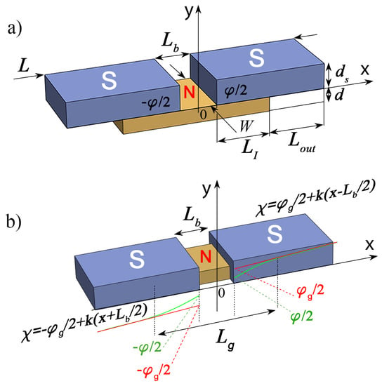
Figure 1.
(a) Sketch of Josephson SN-N-NS bridge and (b) sketch of Josephson SNS bridge. Here, is the distance between the S electrodes, W is the width of the structure, is the length of the SN interface, and d are the thickness of the S and N films, respectively, is the order parameter phase difference across the junctions, is the global phase difference across the junction, and is the asymptotic coordinate dependence of the electrode order parameter phase away from the weak link region.
These structures are now widely used in the fabrication of nano-SQUIDs [1,2,3,4,5,6,7,8,9,10,11] as well as in the design and implementation of digital circuits [12,13,14]. The ordinary metals Nb, NbN [3,4,5,12,15], TiN [8,9,9], Al [2,16,17], Pb [18], Au [19,20,21], and Cu [22] as well as two-dimensional electron gas [23,24] and topological insulators [25,26,27,28,29,30,31,32,33,34,35,36,37,38,39,40,41,42,43,44,45,46] have been used as the weak coupling material of the Josephson elements in these devices. The calculations performed in [47,48,49] indicated the prospect of using SN-N-NS bridges as basic elements of digital and analogue superconducting devices [50].
One of the most important characteristics of the bridges is the relationship between the superconducting current I flowing through them and the phase difference of the order parameters of their superconducting (S) electrodes [51,52]. The question of what the value means and how to determine it correctly depends both on the geometry of the Josephson structure and on the transport properties of its boundaries.
In this paper, we solve this question regarding SN-N-NS Josephson bridges. It is important to note that the developed approach can be applied to any structure in which there is a concentration of supercurrentin S-electrodes in the vicinity of their boundary with the weak coupling region.
2. Correct Determination of as Measured by Experiment
The problem of correctly defining has been conventionally solved in the simplest model, the so-called Rigid Boundary Conditions (RBC), to describe the properties of the S-electrodes. The RBC model has been the workhorse model most often used in the analysis of processes in Josephson junctions [53,54,55,56,57,58]. It is assumed that all nonlinear and non-equilibrium processes in Josephson structures are localized in the weak coupling region between two two superconducting (S) electrodes (see Figure 1b). Reverse effects of these processes on electrode superconductivity are considered to be negligible. The electrodes are in a stationary and equilibrium state, so that the order parameter modules and the anomalous Green functions characterizing their superconducting state are independent of the spatial coordinates and coincide with their equilibrium values calculated for a solitary superconductor. In this model, the setting of a bias current through the Josephson contact is provided by a linearly increasing with the coordinate phase of the order parameter , which experiences a jump at the geometric boundary of the weak coupling region by the value (the red line in Figure 1b). This value is often called the Josephson phase difference at contact [51].
Further research allowed us to formulate the areas of applicability of this model for the case of almost equal thickness and width of the N and S films. It has been demonstrated [59,60,61,62,63,64,65,66] that suppression of superconductivity in S electrodes due to the proximity effect and the effect of depairing of superconducting correlations by bias supercurrent leads to a mismatch between the phases of Green’s function and the order parameter at the NS boundaries, which no longer coincide with each other. For this reason, it is impossible to introduce a physically meaningful Josephson phase difference between the NS interfaces.
The suppression of superconducting correlations in the vicinity of the interfaces of S electrodes with the material of the weak coupling region actually means the spatial expansion of this region. It is no longer determined by the geometric boundaries separating the materials of the structure, so that the Josephson phase difference of the order parameters becomes not a measurable quantity and in no way characterizes the properties of the Josephson structure. The weak coupling region expands up to the values of . This length defines the positions of the regions inside the S electrodes, outside of which the modules of both and the anomalous Green’s functions reach values independent of spatial coordinates and their phases coincide with each other and increase linearly with the growth of the coordinate x along the x-axis. Extrapolation of this linear dependence to the geometric boundaries of materials determines the global Josephson phase difference . The introduction of allows us to consider the Josephson contact as a serial connection of the structure with the current–phase relation and the inductance of the S electrodes. All effects initiated by delocalization of the weak link region (the green line in Figure 1) are taken into account in the shape of the dependence. This provides a junction description convenient for designing and studying processes in devices having such delocalised Josephson contacts.
In [67], it was concluded that the desired parameters of the Josephson contact mA, mV can be achieved at nm, nm. These scales are quite comfortable for modern methods in the CMOS industry. The problem is to obtain such and with accuracy , and these lengths should be implemented with an accuracy up to 1 nm. Because implementation of this accuracy in the bridge-type planar technologies used for superconducting VLSI circuits would require very advanced CMOS nodes, the authors of [67] concluded that this type of junction can be used only in devices in which the parameter spreads are not important.
In fact, such a rigorous conclusion is rather a consequence of the specific geometry of bridge shown in Figure 1b. Recently [47], it was demonstrated that in the bridge geometry shown in Figure 1a there are no such strict restrictions on W, , and d. This is due to the delocalization of the weak region due to the finite transparency of the SN boundaries.
In the microscopic theory of superconductivity [68,69], the presence of a finite transparency of the interface between a massive superconductor and a thin non-superconducting metal is characterized by a suppression parameter . Here, R is the specific boundary resistance, is the coherence length of the S electrodes, and and are the resistivity and decay length, respectively, of the weak link material. Typical values of the suppression parameter at interfaces between Nb and a thin Al film were obtained by comparing theoretical predictions [69] with experimental results [70,71,72] obtained in NbAl-AlOx-Nb and NbAl-AlOx-AlNb tunnel structures. The existence of a finite interface transparency between two normal metals was confirmed experimentally in [73,74,75,76,77,78].
In an SN-N-NS bridge, the finite interface transparency leads to violation of the rigid boundary conditions used in the above estimates [67] and delocalization of the weak coupling region [47] (see Figure 1a). In the limit , both the critical current and the product are mainly determined in these junctions by the suppression parameter rather than by the bridge geometrical factors and W. There is no need for additional structuring of the width of the bridge film [47]. Its width may coincide with the width of the composite electrode, and may be determined by the requirements for the line width of a technological process. In MIT Lincoln Laboratory technology, the lower and upper limits on W (150 nm nm) are determined by the requirement of current carrying capacity and uniformity of the bias current distribution across the width of the electrodes, respectively [79]. There are no strict requirements for the reproducibility of the gap between the electrodes formulated in [67]. Due to the delocalization of processes in the weak link region, its effective size along the direction of the current significantly exceeds . Moreover, numerical calculations show that in SN-N-NS junctions at and , the critical current is practically independent on .
However, it should be noted that the conclusions formulated in [47] were obtained under the assumption that the phase of the electrode order parameter at the SN boundaries does not depend on the coordinate x. Obviously, this assumption is too strong. It does not take into account the heterogeneous nature of the current supply from the N-film to the S-electrode, and leads to a violation of the current conservation law () in composite SN-electrodes. Thus, even in the absence of superconductivity suppression in the S part of a composite SN electrode, should depend on x due to the mutual nature of the proximity effect and the effect of current suppression of superconductivity, and cannot be used as an argument in the current-phase relation. The solution to this problem is to formulate and solve the two-dimensional problem of finding the spatial distribution of the supercurrent in the SN electrodes, determining , and finding the relation. This is exactly the purpose of the present work.
3. Model
We consider a normal (N) metal film connecting two massive superconducting (S) electrodes of length located at a distance from the center of the film (see Figure 1a). Here, is the length of overlap between the S and N layers, while is the length of the free outer part of the S electrode. We place the origin of coordinates on the upper surface of the N film in the middle of the SN-N-NS structure and direct the x and y axes along and perpendicular to the SN interfaces, respectively. The existence of the proximity effect between the N and S materials should lead to the induction of superconducting correlations into the N metal, leading to Josephson coupling between the S banks.
We suppose that the dirty limit condition is satisfied for all the metals, the critical temperature of the weak link material is equal to zero, and its thickness d is much smaller than the decay length . Here, is the diffusion coefficient of the weak link material and is the critical temperature of the S electrode. In the normal metals commonly used in technology, such as Cu, Au, and Al, the coherence length is 50–100 nm (see [78,80] and references therein). Thus, for N layers with a thickness of d 5–10 nm, it is easy to realize a strong inequality between d and . Due to the symmetry of the problem, we may consider it for positive x only.
The conditions
permit us to neglect the suppression of superconductivity in the S film due to proximity effect and reduce the two-dimensional Usadel equations [81] in the N film to a one-dimensional problem [47,49]:
Here, and are Usadel Green’s functions, are Matsubara frequencies normalized on , the coordinate x is normalized on , the modulus of the order parameter in the S electrode is normalized on , and and are the resistivity and coherence length of the S film, respectively.
Due to (1), we assume that the suppression of superconductivity in the S electrodes is negligible and that the value of the critical junction current is significantly less than the preparation current of the S films. Under these conditions from the Usadel equation in the S electrodes, it follows that in this approximation the phases of the order parameter and anomalous Usadel Green’s functions coincide with each other, while their modules equal their equilibrium values in a superconductor at a given temperature T:
The phase obeys the Laplace equation
It is convenient to normalize the x and y coordinates in (6) as well as all of the geometrical lengths on Equations (2), (4) and (6) must be supplemented by the boundary conditions.
At , they are determined from the requirement of continuity of the functions and their first derivatives:
At ,
and at ,
where and are the real and imaginary parts of , respectively.
At , , , and , , which follow from the demand of absence of any supercurrent across the interfaces
We further assume that the characteristic size of the S electrodes significantly exceeds the characteristic lengths () at which a spatial redistribution of the supercurrent density
in the S electrodes is possible. Under this condition, at there is a uniform distribution of the superconducting current density over the thickness of the S and N films, that is, and
where I is a full supercurrent flow across the junction. Expression (12) determines the boundary condition at .
The last boundary condition at follows from the current conservation low as well. It reads that decay of supercurrent in the weak link film at a point x located under the S electrode should be equal to the density of supercurrent injected at this point into this S electrode:
where , , and W is the width of the structure.
The boundary value problem formulated above was solved by numerical methods. It is naturally divided into two interrelated tasks. The first consists of calculating the distribution of the supercurrent (15) along the normal film, that is, in solving the boundary value problem (2), (4), (7)–(10) for a given phase distribution . The second task is to use the finite element method to find the dependencies of and by solving the Laplace Equation (6) with the boundary conditions (10), (13), (14). The solution of the Laplace equation is determined up to a constant. We chose its value from the condition .
Calculation of current characteristics can be accomplished using the iterative method for a given phase . At the zeroth iteration, a calculation is made for a constant value of the superconducting phase along the S electrode. The obtained value of the total current I and the derivative of the current along the electrode are used as the boundary conditions for solving the problem for the S electrode. In the next step, we substitute the resulting distribution into the Usadel’s Equations (2) and (4). Then, the iterative cycle is repeated until the value of the critical current stops changing. With the values of the parameters under consideration, four iterative cycles are sufficient for this. Extrapolation of the linear dependence obtained in the region on the boundary of the composite SN electrode with bridge film determines , and allows us to find the desired dependence .
In the practical implementation of the calculation method described above, we limited ourselves to the following set of parameters: , , , , , , . We performed the calculation for two values: and . The calculation results are shown in Figure 2, Figure 3, Figure 4 and Figure 5.
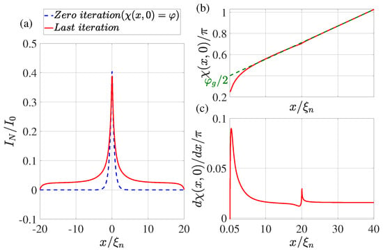
Figure 2.
(a) The coordinate dependence of the current flowing through the N film. The dotted blue line shows the result obtained at the zeroth iteration (), while the solid red line shows the dependence obtained at the last iteration. (b) Distribution of phase of the superconducting order parameter at the last iteration. The dotted green line shows the linear extrapolation of the function from the region . (c) The derivative of the phase of the order parameter as a function of coordinate x at the last iteration. Calculations have been performed for , , , , , , , , .
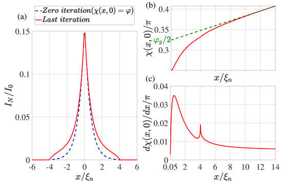
Figure 3.
(a) The coordinate dependence of the current flowing through the N film. The dotted blue line shows the result obtained at the zeroth iteration (), while the solid red line shows the dependence obtained at the last iteration. (b) Distribution of phase of the superconducting order parameter at the last iteration. The dotted green line shows the linear extrapolation of the function from the region . (c) The derivative of the phase of the order parameter as a function of coordinate x at the last iteration. Calculations have been performed for , , , , , , , , .
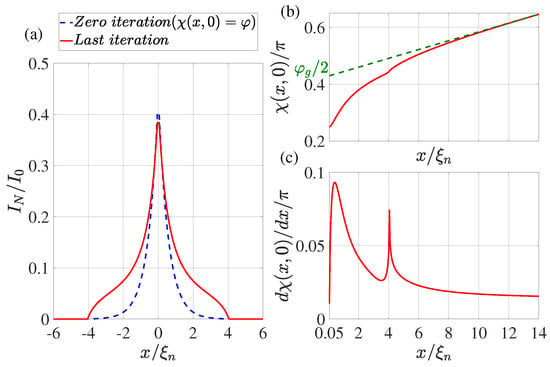
Figure 4.
(a) The coordinate dependence of the current flowing through the N film. The dotted blue line shows the result obtained at the zeroth iteration (), while the solid red line shows the dependence obtained at the last iteration. (b) Distribution of phase of the superconducting order parameter at the last iteration. The dotted green line shows the linear extrapolation of the function from the region . (c) The derivative of the phase of the order parameter as a function of coordinate x at the last iteration. Calculations have been performed for , , , , , , , , .
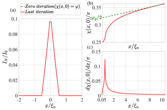
Figure 5.
(a) The coordinate dependence of the current flowing through the N film. The dotted blue line shows the result obtained at the zeroth iteration (), while the solid red line shows the dependence obtained at the last iteration. (b) Distribution of phase of the superconducting order parameter at the last iteration. The dotted green line shows the linear extrapolation of the function from the region . (c) The derivative of the phase of the order parameter as a function of coordinate x at the last iteration. Calculations have been performed for , , , , , , , , .
4. Supercurrent Distribution in the N Part of SN Electrodes
The dotted blue line in Figure 2a, Figure 3a, Figure 4a and Figure 5a shows the supercurrent distribution in the N part of SN electrodes at the initial step of iteration. It can be seen that at (see Figure 2a) in this step the current completely outflows from the N layer into the S film at a characteristic length of . Note that it is this current distribution that was used earlier in [47] when calculating the parameters of SN-N-NS bridges. The iterative solution of the problem presented in Figure 2a by the solid red line shows that the area in which the currents are redistributed between the N and S films is expanding. Moreover, part of the full current continues to flow along the N layer even away from the bridge, reaching a value that is weakly dependent on x. There is practically no leakage of current from the N to the S part of the SN electrode in this area. This component of the current finally leaves the N layer in the vicinity of The area in which weakly depends on x shrinks with decreasing . Thus, with (see Figure 3a and Figure 4a), the difference in the dependencies of at the initial (solid blue line) and final (dotted red line) iteration stages is no longer so significant. The smaller it is, the larger the parameter , that is, the larger . Finally, for , the current component turns out to be independent of x. In this case, the current is injected into the S film through a small area without changing the phase of the order parameter along the SN boundary, meaning that . This is confirmed by the numerical calculations for presented in Figure 5a.
5. Spatial Dependence of the Order Parameter Phase along the SN Interface
It is convenient to analyze the nature of current leakage from the N film into the S electrode by examining the coordinate dependencies of the phase of the superconductor order parameter along the SN boundary shown in Figure 2b,c, Figure 3b,c, Figure 4b,c and Figure 5b,c. It can be seen that regardless of the values of in the vicinity of there is a sharp increase in the derivatives to values several times larger than their values in the region of . After reaching the maximum, the derivatives decrease, experiencing a singularity at due to the final leakage of current into the S electrode.
This behavior of indicates a significant concentration of components of the current density in the vicinity of .
Figure 6 and Figure 7 show spatial distributions of and supercurrent components in the SN-N-NS bridge calculated for and . These spatial distributions clearly demonstrate that in the region with , the concentration of the current component really occurs in an area whose thickness is about 4 times less than . The characteristic scale of the injection area of the current component into the S electrode is approximately equal to . With , this is completely consistent with the theoretical estimate of the size of this region in [47].
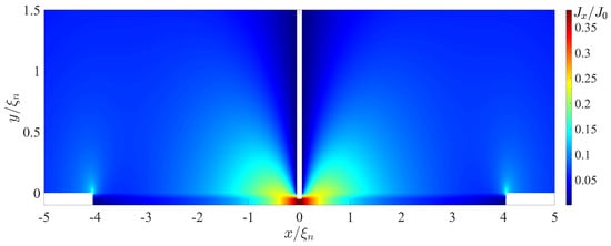
Figure 6.
Coordinate dependence of the component of the supercurrent density calculated for , , , , , , , , .
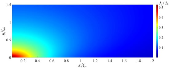
Figure 7.
Coordinate dependence of the component of the supercurrent density calculated for , , , , , , , , .
It should be noted that the difference between and is due to the fact that is determined by the value at , while plays the role of the Josephson penetration depth and is inversely proportional to the square root of the local value of critical current density of the SN interface.
The concentration of the current component leads to an increase in the local inductance value per unit length of this region, which is inversely proportional to the characteristic scale of the current concentration region. This scale turns out to be significantly less than . To extract the additional contribution in from the magnitude of the linear inductance of the S-electrode , we must determine the magnitude of :
as shown in Figure 2b, Figure 3b, Figure 4b and Figure 5b. The dotted line in Figure 2b, Figure 3b, Figure 4b and Figure 5b shows the asymptotic dependence of for large values of x, which determines the value of for . This definition of opens up the possibility of representing the SN-N-NS structure in the form of two bundled elements connected in series, namely, the Josephson junction with CPR and the linear inductance of the S film.
Such an equivalent scheme of Josephson contact actually implies taking into account part of the inductance of the S electrodes in the form of changing the shape of contact current–phase relation. With this description, the part of the S electrodes () in which there is a noticeable deviation of the dependence of from the linear one formally turns out to belong to the weak coupling region. The calculation results presented in Figure 2b, Figure 3b, Figure 4b and Figure 5b allow us to conclude that and weakly depend on and .
It is interesting to note that a completely opposite procedure was proposed earlier in the RBC model [82]. In [82], the authors suggested describing a Josephson contact with non-sinusoidal dependence as a series connection of inductance and contact with a sinusoidal of the relation.
6. Current–Phase Relation
Our numerical calculations show that the shape of the current–phase relation for and (see Figure 8) differs slightly from the one calculated earlier in [47]. It is close to a sinusoidal shape; however, unlike the results obtained in [47], the maximum in is slightly shifted not to the area of but towards . Such deformation is typical for Josephson structures, as the superconductivity of their electrodes is suppressed by the current flowing through them [59,61,63]. This indicates that in SN-N-NS bridges in the region there is a slight suppression of the superconductivity induced into the N film by the current injected into it.
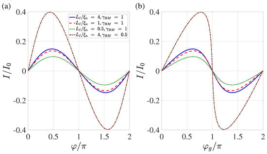
Figure 8.
Current–phase relation (a) and dependence of current on the global phase (b) calculated for four combinations of and . These combinations are (), (), (), and (). Other parameters are , , , , , .
In contrast, the deviation of from the sinusoidal shape turns out to be significant (see Figure 8a). It can be seen that the critical current achieved at , and that the parameters and are both dependent on and .
Figure 9 shows the dependence of the critical current and the global critical phase on the overlap length calculated for different values of the suppression parameters . The points on the curves in Figure 9b indicate positions in the N film that are spaced from by the characteristic length (3) calculated for .
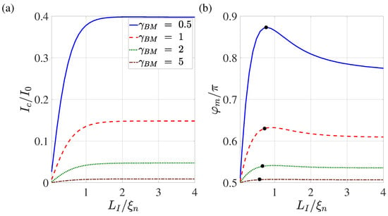
Figure 9.
Dependence of the critical current (a) and the corresponding global phase (b) on the overlap length calculated for . Other parameters: , , , , , . The black dots on the curves indicate the values of functions obtained at a distance removed from by an amount equal to the effective coherence length at .
It can be seen that with both of these parameters are weakly dependent on . With such a noticeable overlap of the S and N films, part of the current has the ability to flow through the N film for a sufficiently long distance before leaking into the S electrode in a vicinity of . This decreases the current concentration in the S film in the vicinity of . At 2, these two areas of current leakage overlap. With a further decrease in , the current concentration region in the S-electrode is compressed and the additional contribution to linear inductance increases. This leads to an increase in . At , the mechanisms of suppression of superconductivity by current injected into the N region are most pronounced. This is accompanied by a decrease in the critical current; consequently, .
Figure 10 shows the dependencies of the critical current and on the suppression parameter for various overlap lengths . In full accordance with the results presented in Figure 9, it can be seen that with the growth of the dependencies of and appear out on the universal curves, demonstrating the independence of these parameters from .
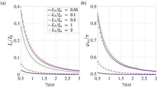
Figure 10.
Dependence of the critical current (a) and the corresponding global phase (b) on the suppression parameter calculated for . Other parameters: , , , , , .
7. Discusion
The performed study of electronic transport in planar Josephson SN-N-NS devices clearly demonstrates that the spatial redistribution of the supercurrent in the electrodes results in delocalization of their weak link region and a significant change in the shape of current–phase relation in these structures.
Our predictions can be verified experimentally by direct measurements of the current–phase relationship of these structures as well as by experimental study of the predicted dependence shown in Figure 9.
We have shown that as the length of the of the SN interface decreases, the weakest place in the weak link region moves from the N metal to the SN boundaries. In fact, as shown in Figure 9, for values of greater than , the critical current of the structure does not depend on . As decreases, the current density injected into the S electrode not only increases, it becomes more spatially homogeneous, meaning that becomes directly proportional to . It is important to note that the degree of symmetry of such a double-barrier structure is determined by the difference in the length of the SN boundaries, and not by the difference in their transparency coefficients.
In the experimental study of structures in which a topological insulator plays the role of a normal metal, this remark is particularly important. The decay length in ballistic channels carrying superconducting current in topological materials can significantly exceed the of dirty films of normal metals. Because of this, the ratio can be easily realised in a real experimental situation ( nm). In this case, the subject of experimental research is not the transport properties of a topological insulator; rather, it is the properties of its least-extended boundary with a superconducting electrode. As the transparency of the SN boundary is not much different from unity, the temperature dependence of the critical current of such a structure does not differ markedly from that predicted for pure ballistic contacts. Therefore, the fact that the experimental dependence coincides with the theoretical dependence for purely ballistic contacts does not provide a clear indication as to which of the structures (SNS or SINIS) was actually studied. Thus, in [45], the presence of two critical currents was detected in the structures obtained by sputtering of Nb on top of Fe-doped BiSbTe2Se flake. According to the authors, the existence of the second critical current results from the intrinsic superconductivity of the Nb–Fe-doped BiSbTe2Se interface. On the basis of the conclusions obtained from this work, the fact of the existence of two critical currents can be interpreted in a different way. If the Nb–Fe-doped BiSbTe2Se–Nb contact is not an SNS but an asymmetric SINIS structure, then its critical current is determined by the least extended SN boundary, and the second critical current (a voltage jump on the I-V curve at a finite value of a bias current) occurs as a result of the transition to the normal state of the second-most extended SN interface. From our point of view, the experimental determination of the dependence should be an important first step in the study of the parameters of SN-N-NS structures, as it permits experimental evaluation of such important parameters as as well as understanding the type of Josephson contact (SNS or SINIS) realized by the geometry of the SN-N-NS contact selected for subsequent experimental studies.
It should be noted that the predicted deformation of the shape of current–phase relationship should be present in the SN-N-NS contacts studied here as well as in any Josephson structure where there is a concentration or other redistribution of the superconducting current in the regions of the S electrodes bordering the weak coupling region, for example, in Dayem and variable thickness bridges.
In Dayem bridges, the effective cross-section of the area where the current is concentrated in the S electrodes decreases due to the narrowing of the width of this area [83]. In variable thickness bridges, the current is concentrated in both the thickness and width of the S electrodes. As in the case of SN-N-NS bridges, the current concentration in DB and BVT structures should be accompanied by an increase in the local values of the inductance of the electrodes per unit of their length, i.e., their significant deviation from the linear inductance of S films away from the constriction. As a consequence, this should lead to the experimental shape of the current phase relation of SN-N-NS, BVT, and DB structures determined using both rf and dc SQUIDs providing and not . The fact that the CPR experimentally obtained in Dayem bridges [15,23,24,27,29,35,84,85] has a shape that coincides with that shown in Figure 8 indirectly confirms the correctness of our results. We emphasise again that in addition to containing information about the contacts themselves, the current phase dependencies obtained experimentally in these works depend on the structure of the current redistribution in their electrodes.
8. Conclusions
The approach we have demonstrated in this paper allows calculation of the parameters of the equivalent scheme of SN-N-NS, BVT, and DB structures. Their representation in the form of a serial connection of the Josephson contact having and the linear inductance of conductive electrodes is useful for the interpretation of experimental data in bridges [13,86], analysis of processes in nano-SQUIDs [1,2,3,4,5,6,7,8,9,10,11], experimental determination of inductance in various low-current superconducting devices [3,9], and in the design of digital circuits [12,13,14].
The data presented in Figure 8, Figure 9 and Figure 10 allow us to conclude that the conclusions formulated in [47] about the prospects of using SN-N-NS contacts as control elements of superconducting digital devices are correct if the following conditions are met: the overlapping area of S and N films should exceed ; and the suppression parameter should be of the order of one. In this case, the characteristic size of the contact is approximately equal to , and the shape of the dependence does not differ much from the sinusoidal one. It is important to note that the numerical results presented in this paper should only be considered as orders of magnitude estimates. Exact values can be obtained by generalising the model to a 3D case, which will be the subject of future work.
Our calculations focused on structures with electrodes made of conventional superconducting materials, where the dirty limit conditions are usually met and the isotropic potential of superconducting electron pairing occurs. In contrast, high-temperature superconducting materials are pure metals; their pairing potential is anisotropic, and has a d-wave or p-wave type symmetry.
This difference is significantly manifested at the boundaries of materials with weak coupling regions, leading to the possible generation of subdominant order parameters and spontaneous currents [87,88,89,90,91,92]. However, these effects should mainly affect the magnitude of the critical current of the structures. The concentration of the current in the electrode region bordering on the concentrating current weak link occurs independently of the differences formulated above. This means that delocalisation of the weak coupling region and the associated changes in the shape of the current–phase relationship are universal phenomena which should take place regardless of whether conventional or high-temperature superconductors are used as electrodes. Finally, it is important to note that there are geometries that result in current being concentrated in the electrodes at boundary surfaces with weak coupling.
Author Contributions
Formulation of the model, S.B. and M.K.; calculations, V.R. and S.B.; Data curation, N.K. and I.S.; Formal analysis, I.S. and A.G.; Funding acquisition, M.K. and V.S.; writing—original draft preparation, V.R., S.B. and M.K.; writing—review and editing, I.S., V.S. and A.G. All authors have read and agreed to the published version of the manuscript.
Funding
The investigation of the spatial distribution of the order parameter and current–phase dependence was carried out with the financial support of the Strategic Academic Leadership Programme “Priority-2030” (NUST MISIS Grant No. K2-2022-029). The development of the concept of a nanoscale Josephson contact based on a variable thickness bridge (Section 2, Section 3 and Section 4) was supported by the Russian Science Foundation, Grant No. 20-12-00130 https://rscf.ru/project/20-12-00130/ (accessed on 15 May 2023). The analysis of the electrode influence on the features of current transport was carried out with the help of the Russian Science Foundation, Grant No. 23-72-30004 https://rscf.ru/project/23-72-30004/ (accessed on 15 April 2023). The work of VSS was supported by the Ministry of Science and Higher Education of the Russian Federation (No. FSMG-2023-0014).
Data Availability Statement
The data presented in this study are available on request from the corresponding author.
Acknowledgments
The authors are grateful to V. Boosboom and O.V. Skryabina for useful discussions of the obtained results.
Conflicts of Interest
The authors declare no conflict of interest.
References
- Hao, L.; Macfarlane, J.C.; Gallop, J.C.; Romans, E.; Cox, D.; Hutson, D.; Chen, J. Spatial Resolution Assessment of Nano-SQUIDs Made by Focused Ion Beam. IEEE Trans. Appl. Supercond. 2007, 17, 742–745. [Google Scholar] [CrossRef]
- Vijay, R.; Levenson-Falk, E.M.; Slichter, D.H.; Siddiqi, I. Approaching ideal weak link behavior with three dimensional aluminum nanobridges. Appl. Phys. Lett. 2010, 96, 223112. [Google Scholar] [CrossRef]
- Wang, H.; Yang, R.; Li, G.; Wu, L.; Liu, X.; Chen, L.; Ren, J.; Wang, Z. Inductance analysis of superconducting quantum interference devices with 3D nano-bridge junctions. Supercond. Sci. Technol. 2018, 31, 055015. [Google Scholar] [CrossRef]
- Russo, R.; Esposito, E.; Crescitelli, A.; Gennaro, E.D.; Granata, C.; Vettoliere, A.; Cristiano, R.; Lisitskiy, M. NanoSQUIDs based on niobium nitride films. Supercond. Sci. Technol. 2016, 30, 024009. [Google Scholar] [CrossRef]
- Holzman, I.; Ivry, Y. On-chip integrable planar NbN nanoSQUID with broad temperature and magnetic-field operation range. AIP Adv. 2019, 9, 105028. [Google Scholar] [CrossRef]
- Shishkin, A.G.; Skryabina, O.V.; Gurtovoi, V.L.; Dizhur, S.E.; Faley, M.I.; Golubov, A.A.; Stolyarov, V.S. Planar MoRe-based direct current nanoSQUID. Supercond. Sci. Technol. 2020, 33, 065005. [Google Scholar] [CrossRef]
- Polychroniou, E.; Gallop, J.; Godfrey, T.; Cox, D.; Long, G.; Chen, J.; Romans, E.; Hao, L. Investigation of NanoSQUIDs Fabricated with a Range of Focused Ion Beam Sources. In Proceedings of the Journal of Physics: Conference Series; IOP Publishing: Bristol, UK, 2020; Volume 1559, p. 012015. [Google Scholar]
- Faley, M.I.; Liu, Y.; Dunin-Borkowski, R.E. Titanium nitride as a new prospective material for NanoSQUIDs and superconducting nanobridge electronics. Nanomaterials 2021, 11, 466. [Google Scholar] [CrossRef] [PubMed]
- Faley, M.; Fiadziushkin, H.; Frohn, B.; Schüffelgen, P.; Dunin-Borkowski, R. TiN nanobridge Josephson junctions and nanoSQUIDs on SiN-buffered Si. Supercond. Sci. Technol. 2022, 35, 065001. [Google Scholar] [CrossRef]
- Faley, M.I.; Dunin-Borkowski, R.E. A Self-Flux-Biased NanoSQUID with Four NbN-TiN-NbN Nanobridge Josephson Junctions. Electronics 2022, 11, 1704. [Google Scholar] [CrossRef]
- Meti, L.; Long, G.; Godfrey, T.; Potter, J.; Cox, D.; Chapman, G.; Gallop, J.; Romans, E.; Hao, L. Development of flux-tuneable inductive nanobridge SQUIDs for quantum technology applications. IEEE Trans. Appl. Supercond. 2023, 33, 1–5. [Google Scholar] [CrossRef]
- Shelly, C.D.; See, P.; Ireland, J.; Romans, E.J.; Williams, J.M. Weak link nanobridges as single flux quantum elements. Supercond. Sci. Technol. 2017, 30, 095013. [Google Scholar] [CrossRef]
- Collins, J.A.; Rose, C.S.; Casaburi, A. Superconducting Nb Nanobridges for Reduced Footprint and Efficient Next-Generation Electronics. IEEE Trans. Appl. Supercond. 2022, 33, 1–8. [Google Scholar] [CrossRef]
- Thompson, M.L.; Castellanos-Beltran, M.; Hopkins, P.F.; Dresselhaus, P.D.; Benz, S.P. Effects of Nonsinusoidal Current Phase Relationships on Single Flux Quantum Circuits. IEEE Trans. Appl. Supercond. 2023, 33, 1–5. [Google Scholar] [CrossRef]
- Troeman, A.; Van Der Ploeg, S.; Il’Ichev, E.; Meyer, H.G.; Golubov, A.A.; Kupriyanov, M.Y.; Hilgenkamp, H. Temperature dependence measurements of the supercurrent-phase relationship in niobium nanobridges. Phys. Rev. B 2008, 77, 024509. [Google Scholar] [CrossRef]
- Keijers, W.; Baumans, X.D.; Panghotra, R.; Lombardo, J.; Zharinov, V.S.; Kramer, R.B.; Silhanek, A.V.; Van de Vondel, J. Nano-SQUIDs with controllable weak links created via current-induced atom migration. Nanoscale 2018, 10, 21475–21482. [Google Scholar] [CrossRef] [PubMed]
- Montemurro, D.; Golubev, D.S.; Kubatkin, S.; Tafuri, F.; Bauch, T.; Lombardi, F. Enhanced Josephson coupling in hybrid nanojunctions. Phys. Rev. B 2023, 107, 094517. [Google Scholar] [CrossRef]
- Roditchev, D.; Brun, C.; Serrier-Garcia, L.; Cuevas, J.C.; Bessa, V.H.L.; Milošević, M.V.; Debontridder, F.; Stolyarov, V.; Cren, T. Direct observation of Josephson vortex cores. Nat. Phys. 2015, 11, 332–337. [Google Scholar] [CrossRef]
- Jung, M.; Noh, H.; Doh, Y.J.; Song, W.; Chong, Y.; Choi, M.S.; Yoo, Y.; Seo, K.; Kim, N.; Woo, B.C.; et al. Superconducting junction of a single-crystalline Au nanowire for an ideal Josephson device. ACS Nano 2011, 5, 2271–2276. [Google Scholar] [CrossRef]
- Skryabina, O.; Bakurskiy, S.; Shishkin, A.; Klimenko, A.; Napolskii, K.; Klenov, N.; Soloviev, I.; Ryazanov, V.; Golubov, A.; Roditchev, D.; et al. Environment-induced overheating phenomena in Au-nanowire based Josephson junctions. Sci. Rep. 2021, 11, 15274. [Google Scholar] [CrossRef]
- Sotnichuk, S.V.; Skryabina, O.V.; Shishkin, A.G.; Bakurskiy, S.V.; Kupriyanov, M.Y.; Stolyarov, V.S.; Napolskii, K.S. Long Single Au Nanowires in Nb/Au/Nb Josephson Junctions: Implications for Superconducting Microelectronics. ACS Appl. Nano Mater. 2022, 5, 17059–17066. [Google Scholar] [CrossRef]
- Skryabina, O.; Egorov, S.; Goncharova, A.; Klimenko, A.; Kozlov, S.; Ryazanov, V.; Bakurskiy, S.; Kupriyanov, M.Y.; Golubov, A.; Napolskii, K.; et al. Josephson coupling across a long single-crystalline Cu nanowire. Appl. Phys. Lett. 2017, 110, 222605. [Google Scholar] [CrossRef]
- Spanton, E.M.; Deng, M.; Vaitiekėnas, S.; Krogstrup, P.; Nygård, J.; Marcus, C.M.; Moler, K.A. Current–phase relations of few-mode InAs nanowire Josephson junctions. Nat. Phys. 2017, 13, 1177–1181. [Google Scholar] [CrossRef]
- Hart, S.; Cui, Z.; Ménard, G.; Deng, M.; Antipov, A.E.; Lutchyn, R.M.; Krogstrup, P.; Marcus, C.M.; Moler, K.A. Current-phase relations of InAs nanowire Josephson junctions: From interacting to multimode regimes. Phys. Rev. B 2019, 100, 064523. [Google Scholar] [CrossRef]
- Williams, J.; Bestwick, A.; Gallagher, P.; Hong, S.S.; Cui, Y.; Bleich, A.S.; Analytis, J.; Fisher, I.; Goldhaber-Gordon, D. Unconventional Josephson effect in hybrid superconductor-topological insulator devices. Phys. Rev. Lett. 2012, 109, 056803. [Google Scholar] [CrossRef]
- Cho, S.; Dellabetta, B.; Yang, A.; Schneeloch, J.; Xu, Z.; Valla, T.; Gu, G.; Gilbert, M.J.; Mason, N. Symmetry protected Josephson supercurrents in three-dimensional topological insulators. Nat. Commun. 2013, 4, 1689. [Google Scholar] [CrossRef] [PubMed]
- Sochnikov, I.; Bestwick, A.J.; Williams, J.R.; Lippman, T.M.; Fisher, I.R.; Goldhaber-Gordon, D.; Kirtley, J.R.; Moler, K.A. Direct measurement of current-phase relations in superconductor/topological insulator/superconductor junctions. Nano Lett. 2013, 13, 3086–3092. [Google Scholar] [CrossRef] [PubMed]
- Galletti, L.; Charpentier, S.; Iavarone, M.; Lucignano, P.; Massarotti, D.; Arpaia, R.; Suzuki, Y.; Kadowaki, K.; Bauch, T.; Tagliacozzo, A.; et al. Influence of topological edge states on the properties of Al/Bi 2 Se 3/Al hybrid Josephson devices. Phys. Rev. B 2014, 89, 134512. [Google Scholar] [CrossRef]
- Sochnikov, I.; Maier, L.; Watson, C.A.; Kirtley, J.R.; Gould, C.; Tkachov, G.; Hankiewicz, E.M.; Brüne, C.; Buhmann, H.; Molenkamp, L.W.; et al. Nonsinusoidal current-phase relationship in Josephson junctions from the 3D topological insulator HgTe. Phys. Rev. Lett. 2015, 114, 066801. [Google Scholar] [CrossRef]
- Kurter, C.; Finck, A.D.; Hor, Y.S.; Van Harlingen, D.J. Evidence for an anomalous current–phase relation in topological insulator Josephson junctions. Nat. Commun. 2015, 6, 7130. [Google Scholar] [CrossRef]
- Wiedenmann, J.; Bocquillon, E.; Deacon, R.S.; Hartinger, S.; Herrmann, O.; Klapwijk, T.M.; Maier, L.; Ames, C.; Brüne, C.; Gould, C.; et al. 4 π-periodic Josephson supercurrent in HgTe-based topological Josephson junctions. Nat. Commun. 2016, 7, 10303. [Google Scholar] [CrossRef]
- Bocquillon, E.; Deacon, R.S.; Wiedenmann, J.; Leubner, P.; Klapwijk, T.M.; Brüne, C.; Ishibashi, K.; Buhmann, H.; Molenkamp, L.W. Gapless Andreev bound states in the quantum spin Hall insulator HgTe. Nat. Nanotechnol. 2017, 12, 137–143. [Google Scholar] [CrossRef] [PubMed]
- Dufouleur, J.; Veyrat, L.; Dassonneville, B.; Xypakis, E.; Bardarson, J.H.; Nowka, C.; Hampel, S.; Schumann, J.; Eichler, B.; Schmidt, O.; et al. Weakly-coupled quasi-1D helical modes in disordered 3D topological insulator quantum wires. Sci. Rep. 2017, 7, 45276. [Google Scholar] [CrossRef]
- Li, C.; De Ronde, B.; De Boer, J.; Ridderbos, J.; Zwanenburg, F.; Huang, Y.; Golubov, A.; Brinkman, A. Zeeman-effect-induced 0- π transitions in ballistic Dirac semimetal Josephson junctions. Phys. Rev. Lett. 2019, 123, 026802. [Google Scholar] [CrossRef] [PubMed]
- Kayyalha, M.; Kargarian, M.; Kazakov, A.; Miotkowski, I.; Galitski, V.M.; Yakovenko, V.M.; Rokhinson, L.P.; Chen, Y.P. Anomalous low-temperature enhancement of supercurrent in topological-insulator nanoribbon Josephson junctions: Evidence for low-energy Andreev bound states. Phys. Rev. Lett. 2019, 122, 047003. [Google Scholar] [CrossRef] [PubMed]
- Kunakova, G.; Bauch, T.; Trabaldo, E.; Andzane, J.; Erts, D.; Lombardi, F. High transparency Bi2Se3 topological insulator nanoribbon Josephson junctions with low resistive noise properties. Appl. Phys. Lett. 2019, 115, 172601. [Google Scholar] [CrossRef]
- Kunakova, G.; Surendran, A.P.; Montemurro, D.; Salvato, M.; Golubev, D.; Andzane, J.; Erts, D.; Bauch, T.; Lombardi, F. Topological insulator nanoribbon Josephson junctions: Evidence for size effects in transport properties. J. Appl. Phys. 2020, 128, 194304. [Google Scholar] [CrossRef]
- Stolyarov, V.S.; Yakovlev, D.S.; Kozlov, S.N.; Skryabina, O.V.; Lvov, D.S.; Gumarov, A.I.; Emelyanova, O.V.; Dzhumaev, P.S.; Shchetinin, I.V.; Hovhannisyan, R.A.; et al. Josephson current mediated by ballistic topological states in Bi2Te2. 3Se0.7 single nanocrystals. Commun. Mater. 2020, 1, 38. [Google Scholar] [CrossRef]
- Kim, N.H.; Kim, H.S.; Hou, Y.; Yu, D.; Doh, Y.J. Superconducting quantum interference devices made of Sb-doped Bi2Se3 topological insulator nanoribbons. Curr. Appl. Phys. 2020, 20, 680–685. [Google Scholar] [CrossRef]
- Kayyalha, M.; Kazakov, A.; Miotkowski, I.; Khlebnikov, S.; Rokhinson, L.P.; Chen, Y.P. Highly skewed current–phase relation in superconductor–topological insulator–superconductor Josephson junctions. NPJ Quantum Mater. 2020, 5, 7. [Google Scholar] [CrossRef]
- Zhang, J.; Jalil, A.R.; Tse, P.L.; Kölzer, J.; Rosenbach, D.; Valencia, H.; Luysberg, M.; Mikulics, M.; Panaitov, G.; Grützmacher, D.; et al. Proximity-Effect-Induced Superconductivity in Nb/Sb2Te3-Nanoribbon/Nb Junctions. Ann. Der Phys. 2020, 532, 2000273. [Google Scholar] [CrossRef]
- Tse, P.L.; Tian, F.; Mugica-Sanchez, L.; Ruger, O.; Undisz, A.; Möthrath, G.; Ronning, C.; Takahashi, S.; Lu, J.G. Microwave AC Resonance Induced Phase Change in Sb2Te3 Nanowires. Nano Lett. 2020, 20, 8668–8674. [Google Scholar] [CrossRef] [PubMed]
- Stolyarov, V.S.; Pons, S.; Vlaic, S.; Remizov, S.V.; Shapiro, D.S.; Brun, C.; Bozhko, S.I.; Cren, T.; Menshchikova, T.V.; Chulkov, E.V.; et al. Superconducting long-range proximity effect through the atomically flat interface of a Bi2Te3 topological insulator. J. Phys. Chem. Lett. 2021, 12, 9068–9075. [Google Scholar] [CrossRef] [PubMed]
- Stolyarov, V.S.; Roditchev, D.; Gurtovoi, V.L.; Kozlov, S.N.; Yakovlev, D.S.; Skryabina, O.V.; Vinokur, V.M.; Golubov, A.A. Resonant Oscillations of Josephson Current in Nb-Bi2Te2.3Se0.7-Nb Junctions. Adv. Quantum Technol. 2022, 5, 2100124. [Google Scholar] [CrossRef]
- Kudriashov, A.; Babich, I.; Hovhannisyan, R.A.; Shishkin, A.G.; Kozlov, S.N.; Fedorov, A.; Vyalikh, D.V.; Khestanova, E.; Kupriyanov, M.Y.; Stolyarov, V.S. Revealing Intrinsic Superconductivity of the Nb/BiSbTe2Se Interface. Adv. Funct. Mater. 2022, 32, 2209853. [Google Scholar] [CrossRef]
- Surendran, P.A.; Montemurro, D.; Kunakova, G.; Palermo, X.; Niherysh, K.; Trabaldo, E.; Golubev, D.; Andzane, J.; Erts, D.; Lombardi, F.; et al. Current-phase relation of a short multi-mode Bi2Se3 topological insulator nanoribbon Josephson junction with ballistic transport modes. Supercond. Sci. Technol. 2023, 36, 064003. [Google Scholar] [CrossRef]
- Soloviev, I.; Bakurskiy, S.; Ruzhickiy, V.; Klenov, N.; Kupriyanov, M.; Golubov, A.; Skryabina, O.; Stolyarov, V. Miniaturization of Josephson Junctions for Digital Superconducting Circuits. Phys. Rev. Appl. 2021, 16, 044060. [Google Scholar] [CrossRef]
- Marychev, P.M.; Vodolazov, D.Y. A Josephson junction based on a highly disordered superconductor/low-resistivity normal metal bilayer. Beilstein J. Nanotechnol. 2020, 11, 858–865. [Google Scholar] [CrossRef]
- Bosboom, V.; der Vegt, J.J.W.V.; Kupriyanov, M.Y.; Golubov, A.A. Selfconsistent 3D model of SN-N-NS Josephson junctions. Supercond. Sci. Technol. 2021, 34, 115022. [Google Scholar] [CrossRef]
- Cuthbert, M.; DeBenedictis, E.; Fagaly, R.L.; Fagas, G.; Febvre, P.; Fourie, C.; Frank, M.; Gupta, D.; Herr, A.; Holmes, D.S.; et al. International roadmap for devices and systems. In Cryogenic Electronics and Quantum Information Processing; IEEE: Piscataway, NJ, USA, 2022. [Google Scholar]
- Likharev, K.K. Superconducting weak links. Rev. Mod. Phys. 1979, 51, 101–159. [Google Scholar] [CrossRef]
- Golubov, A.A.; Kupriyanov, M.Y.; Il’ichev, E. The current-phase relation in Josephson junctions. Rev. Mod. Phys. 2004, 76, 411–469. [Google Scholar] [CrossRef]
- Likharev, K.K. Vortex motion and the Josephson effect in superconducting thin bridges. Zh. Eksp. Teor. Fiz. 1971, 61, 1700–1711. [Google Scholar]
- Kulik, I.O.; Omel’yanchuk, A.N. Contribution to the microscopic theory of the Josephson effect in superconducting bridges. Pis’ma Zh. Eksp. Teor. Fiz. 1975, 21, 216–219. [Google Scholar]
- Likharev, K.K.; Yakobson, L.A. Dynamical properties of superconducting filaments of finite length. Zh. Eksp. Teor. Fiz. 1975, 68, 1150–1160. [Google Scholar]
- Likharev, K.K. The relation Js(φ) for SNS bridges of variable thickness. Pis’ma Zh. Tekh. Fiz. 1976, 2, 29. [Google Scholar]
- Kupriyanov, M.Y.; Likharev, K.K.; Lukichev, V.F. Influence of effective electron interaction on the critical current of Josephson weak links. Zh. Eksp. Teor. Fiz. 1982, 83, 431–441. [Google Scholar] [CrossRef]
- Dubos, P.; Courtois, H.; Pannetier, B.; Wilhelm, F.K.; Zaikin, A.D.; Schön, G. Josephson critical current in a long mesoscopic S-N-S junction. Phys. Rev. B 2001, 63, 064502. [Google Scholar] [CrossRef]
- Ivanov, Z.G.; Kupriyanov, M.Y.; Likharev, K.K.; Meriakri, S.V.; Snigirev, O.V. Boundary-conditions for the Usadel and Eilenberger equations, and properties of dirty SNS sandwich-type junctions. Sov. J. Low. Temp. Phys. 1981, 7, 274–281. [Google Scholar]
- Kupriyanov, M.Y.; Lukichev, V.F. The influence of proximity effect in electrodes on the stationary properties of S-N-S Josephson structures. Sov. J. Low. Temp. Phys. 1982, 8, 526–529. [Google Scholar]
- Zubkov, A.; Kupriyanov, M. Effect of depairing in electrodes on the stationary properties of weak links. Sov. J. Low Temp. Phys. 1983, 5, 279–281. [Google Scholar]
- Barash, Y.S. Anharmonic Josephson current in junctions with an interface pair breaking. Phys. Rev. B 2012, 85, 100503. [Google Scholar] [CrossRef]
- Kupriyanov, M. Effect of a finite transmission of the insulating layer on the properties of SIS tunnel-junctions. JETP Lett. 1992, 56, 399–405. [Google Scholar]
- Golubov, A.; Kupriyanov, M. The current phase relation in Josephson tunnel junctions. JETP Lett. 2015, 81, 335–341. [Google Scholar] [CrossRef]
- Osin, A.S.; Fominov, Y.V. Superconducting phases and the second Josephson harmonic in tunnel junctions between diffusive superconductors. Phys. Rev. B 2021, 104, 064514. [Google Scholar] [CrossRef]
- Osin, A.S.; Fominov, Y.V. Comment on “Josephson Current as a Boundary Condition for Gor’kov Equations. J. Supercond. Nov. Magn. 2022, 36, 55–58. [Google Scholar] [CrossRef]
- Semenov, V.K.; Polyakov, Y.A.; Tolpygo, S.K. Very Large Scale Integration of Josephson-Junction-Based Superconductor Random Access Memories. IEEE Trans. Appl. Supercond. 2019, 29, 1302809. [Google Scholar] [CrossRef]
- Kuprianov, M.Y.; Lukichev, V.F. Effect of boundary transparency on critical current in dirty SS’S structures. Zh. Eksp. Teor. Fiz. 1988, 94, 139–149. [Google Scholar]
- Golubov, A.A.; Kuprianov, M.Y. Josephson effect in SNlNS and SNIS tunnel structures with finite transparency of the SN boundaries. Zh. Eksp. Teor. Fiz. 1989, 96, 1420–1433. [Google Scholar]
- Golubov, A.A.; Houwman, E.P.; Gijsbertsen, J.G.; Krasnov, V.M.; Flokstra, J.; Rogalla, H.; Kupriyanov, M.Y. Proximity effect in superconductor-insulator-superconductor Josephson tunnel junctions: Theory and experiment. Phys. Rev. B 1995, 51, 1073–1089. [Google Scholar] [CrossRef] [PubMed]
- Zehnder, A.; Lerch, P.; Zhao, S.P.; Nussbaumer, T.; Kirk, E.C.; Ott, H.R. Proximity effects in Nb/Al-AlOx-Al/Nb superconducting tunneling junctions. Phys. Rev. B 1999, 59, 8875. [Google Scholar] [CrossRef]
- Brammertz, G.; Poelaert, A.; Golubov, A.A.; Verhoeve, P.; Peacock, A.; Rogalla, H. Generalized proximity effect model in superconducting bi- and trilayer films. J. Appl. Phys. 2001, 90, 355–364. [Google Scholar] [CrossRef]
- Baxter, D.V.; Steenwyk, S.D.; Bass, J.; Pratt, W.P. Resistance and spin-direction memory loss at Nb/Cu interfaces. J. Appl. Phys. 1999, 85, 4545. [Google Scholar] [CrossRef]
- Park, W.; Baxter, D.V.; Steenwyk, S.; Moraru, I.; Pratt, W.P.; Bass, J. Measurement of resistance and spin-memory loss (spin relaxation) at interfaces using sputtered current perpendicular-to-plane exchange-biased spin valves. Phys. Rev. B 2000, 62, 1178. [Google Scholar] [CrossRef]
- Sharma, A.; Romero, J.A.; Theodoropoulou, N.; Loloee, R.; Pratt, J.W.P.; Bass, J. Specific resistance and scattering asymmetry of Py/Pd, Fe/V, Fe/Nb, and Co/Pt interfaces. J. Appl. Phys. 2007, 102, 113916. [Google Scholar] [CrossRef]
- Tuuli, E.; Gloos, K. Normal reflection at superconductor - normal metal interfaces due to Fermi surface mismatch. J. Phys. Conf. Ser. 2012, 400, 042066. [Google Scholar] [CrossRef]
- Bass, J. CPP magnetoresistance of magnetic multilayers: A critical review. J. Magn. Magn. Mater. 2016, 408, 244–320. [Google Scholar] [CrossRef]
- Stolyarov, V.S.; Tristan, C.; Christophe, B.; Golovchanskiy, I.A.; Skryabina, O.V.; Kasatonov, D.I.; Khapaev, M.M.; Kupriyanov, M.Y.; Golubov, A.A.; Dimitri, R. Expansion of a superconducting vortex core into a diffusive metal. Nat. Commun. 2018, 2, 2277. [Google Scholar] [CrossRef]
- Tolpygo, S.K.; Bolkhovsky, V.; Rastogi, R.; Zarr, S.; Golden, E.; Weir, T.J.; Johnson, L.M.; Semenov, V.K.; Gouker, M.A. A 150-nm process node of an eight-Nb-layer fully planarized process for superconductor electronics. In Proceedings of the Applied Superconductivity Conference, ASC 2020 Virtual Conference. Superconductivity News Forum (SNF), Virtual, 24 October–7 November 2020; Volume 14, p. STP669 Wk1EOr3B-01. Available online: https://snf.ieeecsc.org/issues/snfissue-no-49-march-2021 (accessed on 15 May 2023).
- Golikova, T.E.; Hubler, F.; Beckmann, D.; Klenov, N.V.; Bakurskiy, S.V.; Kupriyanov, M.Y.; Batov, I.E.; Ryazanov, V.V. Critical current in planar SNS Josephson junctions. JETP Lett. 2012, 96, 668–673. [Google Scholar] [CrossRef]
- Usadel, K.D. Generalized diffusion equation for superconducting alloys. Phys. Rev. Lett. 1970, 25, 507–509. [Google Scholar] [CrossRef]
- Zubkov, A.A.; Kupriyanov, M.Y.; Semyonov, V.K. Steady-state Properties of the Josephson Junction with Direct Conduction. Fiz. Nizk. Temp. 1981, 7, 1365–1371. [Google Scholar]
- Vijay, R.; Sau, J.; Cohen, M.L.; Siddiqi, I. Optimizing anharmonicity in nanoscale weak link Josephson junction oscillators. Phys. Rev. Lett. 2009, 103, 087003. [Google Scholar] [CrossRef]
- Assouline, A.; Feuillet-Palma, C.; Bergeal, N.; Zhang, T.; Mottaghizadeh, A.; Zimmers, A.; Lhuillier, E.; Eddrie, M.; Atkinson, P.; Aprili, M.; et al. Spin-Orbit induced phase-shift in Bi2Se3 Josephson junctions. Nat. Commun. 2019, 10, 126. [Google Scholar] [CrossRef] [PubMed]
- Chen, L.; Wu, L.; Wang, Y.; Pan, Y.; Zhang, D.; Zeng, J.; Liu, X.; Ma, L.; Peng, W.; Wang, Y.; et al. Miniaturization of the Superconducting Memory Cell via a Three-Dimensional Nb Nano-superconducting Quantum Interference Device. ACS Nano 2020, 14, 11002–11008. [Google Scholar] [CrossRef] [PubMed]
- Ruhtinas, A.; Maasilta, I.J. Highly tunable NbTiN Josephson junctions fabricated with focused helium ion beam. arXiv 2023, arXiv:2303.17348. [Google Scholar]
- Golubov, A.A.; Kupriyanov, M.Y. Anomalous proximity effect in d-wave superconductors. JETP Lett. 1998, 67, 501–507. [Google Scholar] [CrossRef]
- Golubov, A.A.; Kupriyanov, M.Y. Surface electron scattering in d-wave superconductors. JETP Lett. 1999, 69, 262–267. [Google Scholar] [CrossRef]
- Bakurskiy, S.V.; Golubov, A.A.; Kupriyanov, M.Y.; Yada, K.; Tanaka, Y. Anomalous surface states at interfaces in p -wave superconductors. Phys. Rev. B 2014, 90, 064513-1–064513-10. [Google Scholar] [CrossRef]
- Bakurskiy, S.; Klenov, N.; Soloviev, I.; Kupriyanov, M.Y.; Golubov, A. Observability of surface currents in p-wave superconductors. Supercond. Sci. Technol. 2017, 30, 044005. [Google Scholar] [CrossRef]
- Bakurskiy, S.; Fominov, Y.V.; Shevchun, A.; Asano, Y.; Tanaka, Y.; Kupriyanov, M.Y.; Golubov, A.; Trunin, M.; Kashiwaya, H.; Kashiwaya, S.; et al. Local impedance on a rough surface of a chiral p-wave superconductor. Phys. Rev. B 2018, 98, 134508. [Google Scholar] [CrossRef]
- Suzuki, S.I.; Golubov, A.A. Robustness of chiral surface current and subdominant s-wave Cooper pairs. arXiv 2023, arXiv:2305.18018. [Google Scholar]
Disclaimer/Publisher’s Note: The statements, opinions and data contained in all publications are solely those of the individual author(s) and contributor(s) and not of MDPI and/or the editor(s). MDPI and/or the editor(s) disclaim responsibility for any injury to people or property resulting from any ideas, methods, instructions or products referred to in the content. |
© 2023 by the authors. Licensee MDPI, Basel, Switzerland. This article is an open access article distributed under the terms and conditions of the Creative Commons Attribution (CC BY) license (https://creativecommons.org/licenses/by/4.0/).