
Zinc-Ion Storage Mechanism of Polyaniline for Rechargeable Aqueous Zinc-Ion Batteries


 ,
, 
Abstract
:1. Introduction
2. Materials and Methods
2.1. Chemical Reagents
2.2. Materials Preparation
2.3. Physicochemical Characterizations
2.4. Electrochemical Measurements
3. Results
4. Conclusions
Supplementary Materials
Author Contributions
Funding
Institutional Review Board Statement
Informed Consent Statement
Data Availability Statement
Acknowledgments
Conflicts of Interest
References
- Ming, J.; Guo, J.; Xia, C.; Wang, W.; Alshareef, H.N. Zinc-Ion Batteries: Materials, Mechanisms, and Applications. Mater. Sci. Eng. R. Rep. 2019, 135, 58–84. [Google Scholar] [CrossRef]
- Jia, X.; Liu, C.; Neale, Z.G.; Yang, J.; Cao, G. Active Materials for Aqueous Zinc Ion Batteries: Synthesis, Crystal Structure, Morphology, and Electrochemistry. Chem. Rev. 2020, 120, 7795–7866. [Google Scholar] [CrossRef] [PubMed]
- Wang, F.; Fan, X.; Gao, T.; Sun, W.; Ma, Z.; Yang, C.; Han, F.; Xu, K.; Wang, C. High-Voltage Aqueous Magnesium Ion Batteries. ACS Central Sci. 2017, 3, 1121–1128. [Google Scholar] [CrossRef] [Green Version]
- Arroyo-de Dompablo, M.E.; Ponrouch, A.; Johansson, P.; Palacín, M.R. Achievements, Challenges, and Prospects of Calcium Batteries. Chem. Rev. 2020, 120, 6331–6357. [Google Scholar] [CrossRef] [PubMed]
- Chen, H.; Xu, H.; Wang, S.; Huang, T.; Xi, J.; Cai, S.; Guo, F.; Xu, Z.; Gao, W.; Gao, C. Ultrafast All-Climate Aluminum-Graphene Battery with Quarter-Million Cycle Life. Sci. Adv. 2017, 3, eaao7233. [Google Scholar] [CrossRef] [PubMed] [Green Version]
- Li, J.-C.; Gong, J.; Zhang, X.; Lu, L.; Liu, F.; Dai, Z.; Wang, Q.; Hong, X.; Pang, H.; Han, M. Alternate Integration of Vertically Oriented CuSe@FeOOH and CuSe@MnOOH Hybrid Nanosheets Frameworks for Flexible In-Plane Asymmetric Micro-supercapacitors. ACS Appl. Energy Mater. 2020, 3, 3692–3703. [Google Scholar] [CrossRef]
- Liu, Y.; Wu, X. Review of Vanadium-Based Electrode Materials for Rechargeable Aqueous Zinc Ion Batteries. J. Energy Chem. 2021, 56, 223–237. [Google Scholar] [CrossRef]
- Sun, W.; Xiao, L.; Wu, X. Facile Synthesis of NiO Nanocubes for Photocatalysts and Supercapacitor Electrodes. J. Alloy. Compd. 2019, 772, 465–471. [Google Scholar] [CrossRef]
- Chen, H.; Qin, H.; Chen, L.; Wu, J.; Yang, Z. V2O5@CNTs as Cathode of Aqueous Zinc Ion Battery with High Rate and High Stability. J. Alloy. Compd. 2020, 842, 155912. [Google Scholar] [CrossRef]
- Wang, J.; Fan, F.; Liu, Y.; Jungjohann, K.L.; Lee, S.W.; Mao, S.X.; Liu, X.; Zhu, T. Structural Evolution and Pulverization of Tin Nanoparticles during Lithiation-Delithiation Cycling. J. Electrochem. Soc. 2014, 161, F3019–F3024. [Google Scholar] [CrossRef] [Green Version]
- Li, Y.; Huang, Z.; Kalambate, P.K.; Zhong, Y.; Huang, Z.; Xie, M.; Shen, Y.; Huang, Y. V2O5 Nanopaper as a Cathode Material with High Capacity and Long Cycle Life for Rechargeable Aqueous Zinc-Ion Battery. Nano Energy 2019, 60, 752–759. [Google Scholar] [CrossRef]
- Huang, J.; Wang, Z.; Hou, M.; Dong, X.; Liu, Y.; Wang, Y.; Xia, Y. Polyaniline-Intercalated Manganese Dioxide Nanolayers as a High-Performance Cathode Material for an Aqueous Zinc-Ion Battery. Nat. Commun. 2018, 9, 2906. [Google Scholar] [CrossRef] [PubMed]
- Li, W.; Han, C.; Gu, Q.; Chou, S.; Wang, J.; Liu, H.; Dou, S. Electron Delocalization and Dissolution-Restraint in Vanadium Oxide Superlattices to Boost Electrochemical Performance of Aqueous Zinc-Ion Batteries. Adv. Energy Mater. 2020, 10, 2001852. [Google Scholar] [CrossRef]
- Du, W.; Xiao, J.; Geng, H.; Yang, Y.; Zhang, Y.; Ang, E.H.; Ye, M.; Li, C.C. Rational-Design of Polyaniline Cathode Using Proton Doping Strategy by Graphene Oxide for Enhanced Aqueous Zinc-Ion Batteries. J. Power Sources 2020, 450, 227716. [Google Scholar] [CrossRef]
- Wang, M.; Zhang, J.; Zhang, L.; Li, J.; Wang, W.; Yang, Z.; Zhang, L.; Wang, Y.; Chen, J.; Huang, Y.; et al. Graphene-like Vanadium Oxygen Hydrate (VOH) Nanosheets Intercalated and Exfoliated by Polyaniline (PANI) for Aqueous Zinc-Ion Batteries (ZIBs). ACS Appl. Mater. Interfaces 2020, 12, 31564–31574. [Google Scholar] [CrossRef]
- Kataoka, F.; Ishida, T.; Nagita, K.; Kumbhar, V.S.; Yamabuki, K.; Nakayama, M. Cobalt-Doped Layered MnO2 Thin Film Electrochemically Grown on Nitrogen-Doped Carbon Cloth for Aqueous Zinc-Ion Batteries. ACS Appl. Energy Mater. 2020, 3, 4720–4726. [Google Scholar] [CrossRef]
- Qin, H.; Chen, L.; Wang, L.; Chen, X.; Yang, Z. V2O5 Hollow Spheres as High Rate and Long Life Cathode for Aqueous Rechargeable Zinc Ion Batteries. Electrochim. Acta 2019, 306, 307–316. [Google Scholar] [CrossRef]
- Alfaruqi, M.H.; Mathew, V.; Gim, J.; Kim, S.; Song, J.; Baboo, J.P.; Choi, S.H.; Kim, J. Electrochemically Induced Structural Transformation in a γ-MnO2 Cathode of a High Capacity Zinc-Ion Battery System. Chem. Mater. 2015, 27, 3609–3620. [Google Scholar] [CrossRef]
- Pan, L.; Pu, L.; Shi, Y.; Sun, T.; Zhang, R.; Zheng, Y.O. Hydrothermal Synthesis of Polyaniline Mesostructures. Adv. Funct. Mater. 2006, 16, 1279–1288. [Google Scholar] [CrossRef]
- Yang, Y.; Wan, M. Chiral Nanotubes of Polyaniline Synthesized by a Template-Free Method. J. Mater. Chem. 2002, 12, 897–901. [Google Scholar] [CrossRef]
- Liu, Y.; Xie, L.; Zhang, W.; Dai, Z.; Wei, W.; Luo, S.; Chen, X.; Chen, W.; Rao, F.; Wang, L.; et al. Conjugated System of PEDOT:PSS-Induced Self-Doped PANI for Flexible Zinc-Ion Batteries with Enhanced Capacity and Cyclability. ACS Appl. Mater. Interfaces 2019, 11, 30943–30952. [Google Scholar] [CrossRef] [PubMed]
- Shi, H.-Y.; Ye, Y.-J.; Liu, K.; Song, Y.; Sun, X. A Long-Cycle-Life Self-Doped Polyaniline Cathode for Rechargeable Aqueous Zinc Batteries. Angew. Chem. Int. Ed. 2018, 57, 16359–16363. [Google Scholar] [CrossRef] [PubMed]
- Alruwashid, F.S.; Dar, M.A.; Alharthi, N.H.; Abdo, H.S. Effect of Graphene Concentration on the Electrochemical Properties of Cobalt Ferrite Nanocomposite Materials. Nanomaterials 2021, 11, 2523. [Google Scholar] [CrossRef] [PubMed]
- Li, J.-C.; Gong, J.; Yang, Z.; Tian, Y.; Zhang, X.; Wang, Q.; Hong, X. Design of 2D Self-Supported Hybrid CuSe@PANI Core/Shell Nanosheet Arrays for High-Performance Flexible Microsupercapacitors. J. Phys. Chem. C 2019, 123, 29133–29143. [Google Scholar] [CrossRef]
- Liu, C.; Neale, Z.; Zheng, J.; Jia, X.; Huang, J.; Yan, M.; Tian, M.; Wang, M.; Yang, J.; Cao, G. Expanded Hydrated Vanadate for High-Performance Aqueous Zinc-Ion Batteries. Energy Environ. Sci. 2019, 12, 2273–2285. [Google Scholar] [CrossRef]
- Geng, H.; Cheng, M.; Wang, B.; Yang, Y.; Zhang, Y.; Li, C.C. Electronic Structure Regulation of Layered Vanadium Oxide via Interlayer Doping Strategy toward Superior High-Rate and Low-Temperature Zinc-Ion Batteries. Adv. Funct. Mater. 2020, 30, 1907684. [Google Scholar] [CrossRef]
- Wu, B.; Zhang, G.; Yan, M.; Xiong, T.; He, P.; He, L.; Xu, X.; Mai, L. Graphene Scroll-Coated α-MnO2 Nanowires as High-Performance Cathode Materials for Aqueous Zn-Ion Battery. Small 2018, 14, 1703850. [Google Scholar] [CrossRef]
- Wang, J.; Wang, J.-G.; Liu, H.; Wei, C.; Kang, F. Zinc Ion Stabilized MnO2 Nanospheres for High Capacity and Long Lifespan Aqueous Zinc-Ion Batteries. J. Mater. Chem. A 2019, 7, 13727–13735. [Google Scholar] [CrossRef]
- Chen, L.; Yang, Z.; Cui, F.; Meng, J.; Jiang, Y.; Long, J.; Zeng, X. Ultrathin MnO2 Nanoflakes Grown on N-Doped Hollow Carbon Spheres for High-Performance Aqueous Zinc Ion Batteries. Mater. Chem. Front. 2020, 4, 213–221. [Google Scholar] [CrossRef]
- Wei, T.; Li, Q.; Yang, G.; Wang, C. Highly Reversible and Long-Life Cycling Aqueous Zinc-Ion Battery Based on Ultrathin (NH4)2V10O25·8H2O Nanobelts. J. Mater. Chem. A 2018, 6, 20402–20410. [Google Scholar] [CrossRef]
- Zhang, N.; Jia, M.; Dong, Y.; Wang, Y.; Xu, J.; Liu, Y.; Jiao, L.; Cheng, F. Hydrated Layered Vanadium Oxide as a Highly Reversible Cathode for Rechargeable Aqueous Zinc Batteries. Adv. Funct. Mater. 2019, 29, 1807331. [Google Scholar] [CrossRef]
- Tang, B.; Fang, G.; Zhou, J.; Wang, L.; Lei, Y.; Wang, C.; Lin, T.; Tang, Y.; Liang, S. Potassium Vanadates with Stable Structure and Fast Ion Diffusion Channel as Cathode for Rechargeable Aqueous Zinc-Ion Batteries. Nano Energy 2018, 51, 579–587. [Google Scholar] [CrossRef]


| Active Materials | Electrolyte | Diffusion Coefficient (cm−2 s−1) | Reference |
|---|---|---|---|
| V2O5@CNTs | 1 M ZnSO4 | 10−10~10−8 (Discharging) 10−12~10−8 (Charging) | [9] |
| V2O5 | 2 M ZnSO4 | 1.32 × 10⁻¹² (Discharging) 3.82 × 10⁻¹¹ (Charging) | [11] |
| V2O5·nH2O | 2 M ZnSO4 | 2.4 × 10⁻⁹ (Discharging) | [13] |
| PANI−VOH | 3 M Zn(CF3SO3)2 | 10−16~10−13 (Discharging) 10−14~10−13 (Charging) | [15] |
| V2O5 | ZnSO4 | 10−11~10−9 (Discharging) | [17] |
| MnVO/VOH | 3 M Zn(CF3SO3)2 | 3.22 × 10⁻¹²~(Discharging) 1.46 × 10⁻¹²~(Charging) | [25] |
| Mn0.15V2O5·nH2O | 1 M Zn(ClO4)2 | 10−12~10−10 (Discharging) | [26] |
| Graphene Scroll Coated α-MnO2 | 2 M ZnSO4 0.2 M MnSO4 | 10−17~10−12 (Discharging) | [27] |
| MnO2 nanospheres | 2 M ZnSO4 0.2 M MnSO4 | 10−15~10−12 (Discharging) | [28] |
| δ-MnO2 | 3 M ZnSO4 0.15 M MnSO4 | 10−13~10−9 (Discharging) 10−11~10−9 (Charging) | [29] |
| (NH4)2V10O25·8H2O | 3 M Zn(CF3SO3)2 | 10−10~10−9 (Discharging) | [30] |
| V5O12·6H2O (VOH) | 3 M Zn(CF3SO3)2 | 10−11~10−10 (Discharging) | [31] |
| K2V8O21 | 2 M ZnSO4 | 1.99 × 10⁻¹¹~2.23 × 10⁻¹⁰ (Discharging) | [32] |
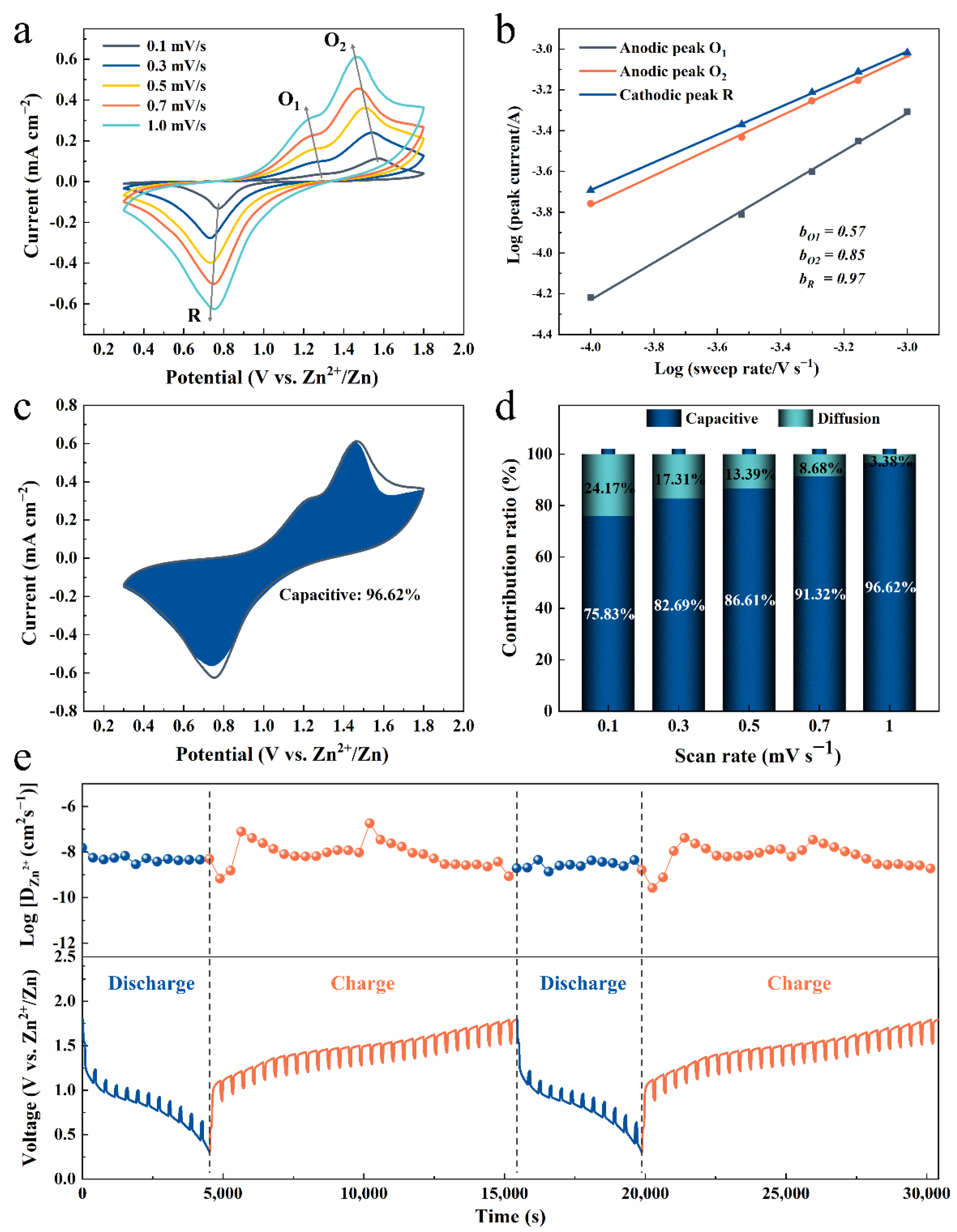
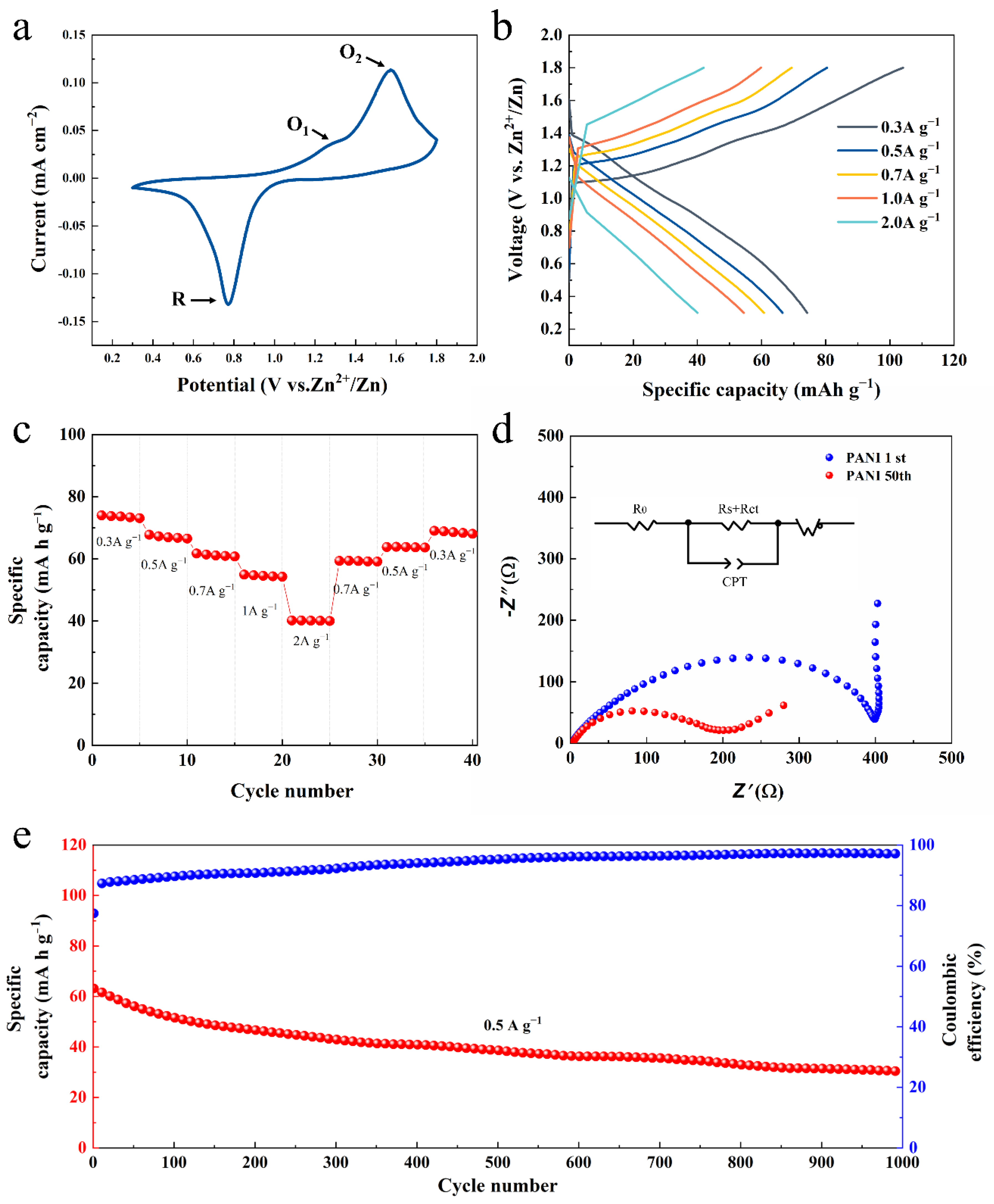
| PANI | 2 M Zn(CF3SO3)2 | 6.25×10⁻⁹~7.82 × 10⁻⁸ (Discharging) 7.69×10⁻¹⁰~1.81 × 10⁻⁷ (Charging) | This work |
Publisher’s Note: MDPI stays neutral with regard to jurisdictional claims in published maps and institutional affiliations. |
© 2022 by the authors. Licensee MDPI, Basel, Switzerland. This article is an open access article distributed under the terms and conditions of the Creative Commons Attribution (CC BY) license (https://creativecommons.org/licenses/by/4.0/).
Share and Cite
Gong, J.; Li, H.; Zhang, K.; Zhang, Z.; Cao, J.; Shao, Z.; Tang, C.; Fu, S.; Wang, Q.; Wu, X. Zinc-Ion Storage Mechanism of Polyaniline for Rechargeable Aqueous Zinc-Ion Batteries. Nanomaterials 2022, 12, 1438. https://doi.org/10.3390/nano12091438
Gong J, Li H, Zhang K, Zhang Z, Cao J, Shao Z, Tang C, Fu S, Wang Q, Wu X. Zinc-Ion Storage Mechanism of Polyaniline for Rechargeable Aqueous Zinc-Ion Batteries. Nanomaterials. 2022; 12(9):1438. https://doi.org/10.3390/nano12091438
Chicago/Turabian StyleGong, Jiangfeng, Hao Li, Kaixiao Zhang, Zhupeng Zhang, Jie Cao, Zhibin Shao, Chunmei Tang, Shaojie Fu, Qianjin Wang, and Xiang Wu. 2022. "Zinc-Ion Storage Mechanism of Polyaniline for Rechargeable Aqueous Zinc-Ion Batteries" Nanomaterials 12, no. 9: 1438. https://doi.org/10.3390/nano12091438
APA StyleGong, J., Li, H., Zhang, K., Zhang, Z., Cao, J., Shao, Z., Tang, C., Fu, S., Wang, Q., & Wu, X. (2022). Zinc-Ion Storage Mechanism of Polyaniline for Rechargeable Aqueous Zinc-Ion Batteries. Nanomaterials, 12(9), 1438. https://doi.org/10.3390/nano12091438