Article

A Study of Ta2O5 Nanopillars with Ni Tips Prepared by Porous Anodic Alumina Through-Mask Anodization

by
Alla I. Vorobjova
1,
Daria I. Tishkevich
2,3,*,
Elena A. Outkina
1,
Dmitry L. Shimanovich
1,
Ihar U. Razanau
2,
Tatiana I. Zubar
2,3,
Anastasia A. Bondaruk
2,
Ekaterina K. Zheleznova
1,2,
Mengge Dong
4,
Dalal A. Aloraini
5,
M. I. Sayyed
6,7,
Aljawhara H. Almuqrin
5,
Maxim V. Silibin
8,
Sergey V. Trukhanov
2 and
Alex V. Trukhanov
2,3
1
Micro- and Nanoelectronics Department, Belarusian State University of Informatics and Radioelectronics, 220013 Minsk, Belarus
2
Scientific-Practical Materials Research Centre of NAS of Belarus, 220072 Minsk, Belarus
3
Laboratory of Single Crystal Growth, South Ural State University, 454080 Chelyabinsk, Russia
4
Department of Resource and Environment, Northeastern University, Shenyang 110819, China
5
Department of Physics, College of Science, Princess Nourah Bint Abdulrahman University, P.O. Box 84428, Riyadh 11671, Saudi Arabia
6
Department of Physics, Faculty of Science, Isra University, Amman 1162, Jordan
7
Department of Nuclear Medicine Research, Institute for Research and Medical Consultations (IRMC), Imam Abdurrahman bin Faisal University (IAU), Dammam 31441, Saudi Arabia
8
Scientific and Technological Park of Biomedecine, I.M. Sechenov First Moscow State Medical University, 119991 Moscow, Russia
*
Author to whom correspondence should be addressed.
Nanomaterials 2022, 12(8), 1344; https://doi.org/10.3390/nano12081344
Submission received: 9 March 2022 / Revised: 1 April 2022 / Accepted: 10 April 2022 / Published: 14 April 2022

Abstract

:
The paper discusses the formation of Ta2O5 pillars with Ni tips during thin porous anodic alumina through-mask anodization on Si/SiO2 substrates. The tantalum nanopillars were formed through porous masks in electrolytes of phosphoric and oxalic acid. The Ni tips on the Ta2O5 pillars were formed via vacuum evaporation through the porous mask. The morphology, structure, and magnetic properties at 4.2 and 300 K of the Ta2O5 nanopillars with Ni tips have been studied using scanning electron microscopy, X-ray diffraction, and vibrating sample magnetometry. The main mechanism of the formation of the Ta2O5 pillars during through-mask anodization was revealed. The superparamagnetic behavior of the magnetic hysteresis loop of the Ta2O5 nanopillars with Ni tips was observed. Such nanostructures can be used to develop novel functional nanomaterials for magnetic, electronic, biomedical, and optical nano-scale devices.

1. Introduction

Magnetic nanoparticles (MNPs) of Fe, Ni, and Co, as well as their chemical compounds have the potential to create high-density magnetic memory, single-electron devices, biosensors, nanoelectrodes, and other devices [1,2,3,4]. Many research groups are actively developing magnetic nanocomposites on the basis of nickel, cobalt, iron, iron oxide, and ferrite nanoparticles for biomedical applications [5,6,7]. The MNPs can be controlled inside an organism by using external magnetic field strength gradients. The possibility of such control makes it possible to use them for various clinical tasks, including magnetic resonance imaging (MRI), targeted drug delivery, and magnetic thermotherapy [8,9].
Our analysis has shown that most research works discuss “free” nanoparticles in the form of powders, suspensions, and aerosols. However, the MNPs usually constitute a part of a film (2D systems) or bulk material (3D systems) in real applications. Simple compaction of the MNPs often leads to a loss or a substantial change in their unique physical characteristics and functional features, even when the particles have a protective coating. Therefore, the optimal structure of an MNPs-containing material can be thought of as single-domain MNPs of a narrow size distribution, which were homogeneously dispersed in a nonmagnetic dielectric matrix. For example, in work [10], maghemite nanoparticles-decorated anodic alumina nanotubes were used for the fluorescent detection of cathepsin B. The diameter of the nanotubes was about 80 nm, the length was about 1 μm, and the diameter of the magnetic nanoparticles was 10 nm. This is a nanocomposite made of 2D/3D material as well.
The chemical and physical properties of the MNPs strongly depend on the synthesis approaches and chemical structures. The formation of nanostructure arrays of various shapes on the base of the MNPs is a promising novel approach of the problem for other applications, such as temperature sensors, thermal energy storage devices, and energy harvesters.
Research in the field of nanostructure array formation is mostly concentrated on carbon nanotubes (CNT) [11,12] and magnetic or semiconducting nanowires or nanodots [13,14,15]. However, the physical vapor deposition (PVD) [11] and chemical vapor deposition (CVD) [16] methods of their synthesis require high temperatures. In other methods, high-temperature annealing is used [17].
As a result, low-temperature synthesis methods are constantly attracting researchers’ attention. The chemical methods for the synthesis of the MPNs from metal-containing compounds (MCC) are the most widely used ones [10,18,19]. Ultrasonic MCCs decomposition, MCCs reduction by various reducing agents, radiation–chemical metal ion reduction, sol–gel technique, MNPs synthesis on a water–air phase interface (Langmuir–Blodgett technology) [20,21], and some other less well-known and investigated methods [22] are included.
One of the popular modern approaches is based on the use of a porous template [23,24,25]. Such templates are completely or partially removed after the nanostructure synthesis. Polycarbonate or thin, porous anodic alumina (TPAA) membranes are usually used for this purpose [26,27,28]. TPAA is almost an ideal template because of its unique structure: it is an ordered matrix of cylindrical pores perpendicular to the surface. The possibility of controlling the structure characteristics by regulating the anodizing parameters such as voltage and duration as well as the electrolyte type and composition [29,30,31] is another advantage of such templates. Applying porous alumina as a template allows forming arrays of vertically ordered NPs with uniform geometrical parameters (diameter, length, and density), which can be readily controlled in a wide range of sizes [32,33]. Additionally, porous alumina is the heat-resistant material that allows carrying out various experiments at high temperatures [34,35]. Furthermore, the TPAA synthesis is simple and inexpensive. It enables the use of a variety of functional substrates, including silicon, sitall, glass, or bulk aluminum [36,37].
MNPs can be synthesized using microelectronics methods on the surface of nanopillars and on the surface or inside of nanotubes. As a result of the interactions in heterogeneous solid-state composites, new properties and possibilities can arise in such systems. For example, the authors of [38,39] reported that tantalum oxide nanopillars systematically self-organized in alumina pores can be formed under certain conditions during TPAA formation in two-layer systems consisting of a relatively thin film of tantalum and a relatively thick film of aluminum.
Within certain limits, the magnetic properties of materials on the base of MNPs can be controlled by changing their size, shape, composition, and structure. However, it is often not feasible to control these parameters during the synthesis of nanoparticles of similar size and chemical composition. As a result, the properties of the same type of nanomaterial can differ significantly. Hence, only complex studies of both the formation peculiarities (mechanisms) and morphological, structural, electronic, and magnetic properties of MNPs with a narrow size distribution allow for formulating necessary synthesis recommendations and finding new promising application directions for the nanomaterials.
For biomedical applications, composite magnetic structures on the basis of MNPs should have three important properties: (1) they should be small (from units to several tens of nm) with a narrow dispersion of topological parameters; (2) they should not assemble into bundles or clusters because magnetic particle agglomeration is undesirable in biomedicine; and (3) they should be controllable by a magnetic field during medical treatment or diagnostics, as for example, during magnetic resonance therapy [11]. After that, the MNPs should be passive as the time of their removal from the human organism can be up to several days. In such cases, superparamagnetic particles of iron oxide coated with gold or platinum are usually used [40]. There are various methods of such superparamagnetic particle synthesis [41], mostly chemical ones. Core–shell particle materials and their synthesis are costly and laborious.
Structured media of this type were traditionally formed using such nano-scale processes as magnetic material etching through a mask, explosive lithography, and vacuum deposition of a magnetic material through a shadow mask [42]. In the work [43] are proposed two sequences for the formation of a metal/porous alumina composite obtained via vacuum deposition. The first sequence is a continuous metal deposition process, and the second is an interrupted deposition scheme, which consists of metal deposition and the mechanical removal of metal from the surface using adhesive tape. In [44], structures of two types were obtained: Ni nanohoneycomb chain structures and Ni nanostructures in the form of double rings. The structures were formed via metal sputtering onto the surface of TPAA substrates. A deposition method with a change in the angle of inclination was used for accurate deposition of a nanothin Ni layer (no more than 10 nm) on a porous alumina. The deposition method using an unusual shadow mask made from porous alumina for the magnetic matrices fabrication with magnetic inclusions of about 60 nm on an area of 1 cm2 is proposed in [45]. In this study, a 300 nm thick alumina membrane with a pore diameter of 60 nm and a pore density of 1010 cm2 was used. Using this method, a Fe layer of 15 nm thick was deposited on a MgO substrate by electron beam evaporation through pores. Then, the membrane was removed in a 10% NaOH solution. In the alumina mask, the pores had a fairly uniform size, with an average diameter of 61 ± 6 nm. The size of Fe nanodots, along with a narrow distribution range, was 58 ± 8 nm. Thus, the combination of a thin mask and directional flow minimizes the shadowing effect and can provide structural uniformity. The authors believe that such methods of physical deposition, despite the complexity of controlling the deposition process, are quite simple to form homogeneous nanostructures. However, there is one significant problem, such as the complex fabrication and difficult work (manipulation) with a thin mask (300 nm) of alumina with through pores.
The advantages of the presented methods are that it is possible to use industrial semiconductor production equipment, which allows the processing of various materials on standard substrates with high reproducibility. The disadvantages are the use of expensive processes for creating high-precision masks for metal deposition. In addition, with a decrease in the size of the elements, the uniformity of deposition over the area of the substrate deteriorates, and to fill nanosized pores, it is necessary to refine the processes of metal-inclined deposition, which complicates the control of deposition processes.
Developing the TPAA pore-filling method, we propose a different anodic dielectric as the filling material: tantalum oxide with further deposition of magnetic nickel on it. In such a case, the initial structure is a two-layer composition including Al as the top layer and Ta as the bottom layer. The method proposed allows the obtaining of ordered pillar “oxide-magnetic” structures that have been actively studied recently because of a wide range of possible applications in nanoelectronics and biomedicine [46,47,48,49]. We propose a method that is closer to industrial production conditions and compatible with silicon micro- and nanoelectronic device production technology.

2. Experimental

The experimental samples were prepared in five stages, as described below. The experimental samples were double-layer thin-film structures of aluminum and tantalum deposited on standard silicon (Si/SiO2) substrates. 76 mm in diameter.
In the first step, polycrystalline films of Al and Ta with the grains close in size to their thickness were deposited by electron-beam evaporation separately or in a single vacuum cycle using a 01NE-7-004 setup “Oratorio-9” (Kaliningrad machine-building factory, Kaliningrad, Russia). The Al layer served as a porous aluminum oxide (Al2O3) formation. The Ta layer was used for tantalum oxide (Ta2O5) pillar formation. It also served as an adhesion sublayer and the bottom electrode. The thickness of the Ta film was controlled by a witness. The thickness of the Al layer was controlled using a quartz microbalance sensor. The parameters of the vacuum deposition of the Al and Ta thin films are listed in Table 1.
In the second step, thin films of porous anodic alumina Al2O3 (TPAA) with an ordered structure were prepared by a two-step anodization method in a combined regime. First, a potential sweep at a constant rate up to a set value was used. Then, the potential was kept constant. The samples of type I were prepared using a 4% aqueous solution of oxalic acid (C2H2O4) under a stationary oxide formation voltage of 40 V and an electrolyte temperature of 14 °C. The samples of type II were prepared using a 4% aqueous solution of phosphoric acid (H3PO4) under a stationary oxide formation voltage of 80 V and an electrolyte temperature of 14 °C. The anodization was carried out in a thermostatic two-electrode cell with magnetic stirring using a graphite cathode.
In the third step, after the through anodization of the Al film and reaching the Ta film, anodic oxidation was continued in the same electrolyte under the voltage sweep conditions with a rate of 0.1 V/s up to 70 V for the oxalic electrolyte and 90 V for the phosphoric electrolyte.
We used a P-5827 potentiostat–galvanostat (Measuring Instruments Factory, Gomel, Belarus) to control the parameters of the anodization processes. A specially developed setup was used to synchronously record the time kinetics of the main anodizing parameters, including current and voltage, and the chronovoltamperometric (CVA) diagrams during the anodization.
Table 2 describes the parameters of the samples obtained after the third stage and the procedures of their preparation (initial matrices—TPAA).
In the fourth stage, a nickel film with a thickness of 90 ± 10 nm was deposited on the surface of the samples. The thickness was determined based on the previous experimental data and theoretical recommendations provided in [50] (Figure 1). The thickness of the coating is chosen based on the TPAA parameters, namely, pore diameter and oxide thickness. When the ratio of the pore diameter to the oxide thickness is ≤1:8, the thickness of the metal deposited should be less than 2d, where d is the Al2O3 pore diameter.
Nickel films were deposited in a magnetron deposition system on the base of a modernized vacuum setup, “Oratorio-5” (Kaliningrad machine-building factory, Kaliningrad, Russia). A target made of Ni with a purity of 99.95% was used for the deposition. The deposition regime was experimentally adjusted to obtain a low controllable deposition rate. The target voltage was 400 V. The temperature of substrate varied between 280 and 300 °C. The residual gas pressure in the chamber was 13.3 Pa. The deposition rate was about 30 nm∙min−1 under such conditions.
In the fifth stage, alumina selective chemical etching was carried out in the electrolyte containing H3PO4 (6 mass%) and CrO3 (1.8 mass%) at a temperature of 85 °C for 3 min. As a result, nickel remained only on top of the Ta2O5 pillars in the form of small tips.
The morphology of the Ta2O5 pillars with Ni tips was studied by scanning electron microscopy (Philips XL 30 S FEG–Ku Leuven, Leuven, Belgium) at a 20 kV accelerating voltage in the SE regime. A statistical analysis of the Ta2O5 pillars was performed using a simple method described in detail in [51]. Smart SEM software was applied to at least three SEM images to calculate the size distribution. X-ray diffraction (XRD) investigation of the prepared samples was carried out using a diffractometer (DRON-3M–NPO Burevestnik, St. Petersburg, Russia) with Cu-Kα radiation at 300 K temperature (λ = 1.542 Å).
The magnetic parameters were measured in the temperature range of 4.2–300 K by a Liquid Helium Free High Field Measurement System (VSM–Cryogenic Limited, London, UK) [52]. The applied magnetic field was ±2 T; the specific magnetization measurement precision σ was ±0.01 A·m2·kg−1.

3. Results and Discussion

3.1. Mechanism of the Ta2O5 Pillar Growth

The scheme in Figure 2 explains the stages of nanopillar formation during the anodization of a two-layer thin-film Al-Ta composition in a combined regime. First, the anodization is carried out under a potential sweep at a constant rate. After reaching the potential value set, the anodization is continued under potentiostatic conditions. During stage A, the aluminum film is porously anodized to a certain depth. In stage B, the porous anodization of aluminum reaches the Ta film. Stage C is the Ta film anodization under the voltage of aluminum oxide formation (UAl). In stage D, Ta2O5 pillars are formed under the voltage of Ta anodization (UTa); reanodization takes place.
The size of the Al2O3 cells and, hence, the distance between the pillars are proportional to the aluminum formation (anodization) voltage. Amorphous Ta oxide fills the central part of the cells with porous Al2O3 during the reanodization (stages C and D). Matrix pore walls consist of amorphous alumina. The depth of the pore filling with Ta2O5 is proportional to the formation voltage during the porous anodization of the aluminum layer (stage C). It also depends on the final stage of the aluminum through anodization. The Ta2O5 pillars formed in stage D repeat the shape of the natural Al2O3 porous mask (TPAA). The height of the pillars is proportional to the tantalum reanodization voltage (stage D).
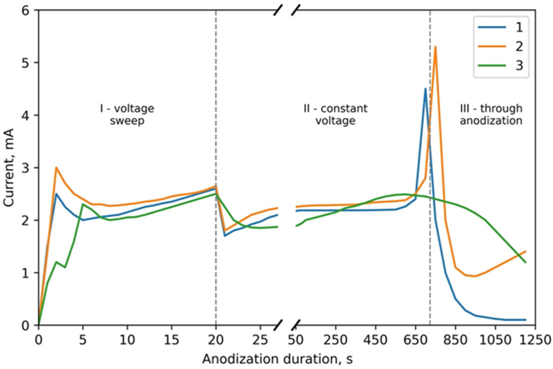
Figure 3 depicts the CVA curves of the simultaneous anodic treatment of the two-layer thin-film composition of Al (1000 nm) on Ta (400 nm) in the 4% aqueous oxalic acid solution. Curve 1 corresponds to sample 1 of type I. Curve 2 shows the anodization of sample 2 of type I. Curve 3 is a comparison curve depicting the usual porous anodization of Al of the same thickness under the same conditions. Anodization was performed in a combined regime. Curves 1 and 3 correspond to the anodization under a voltage sweep from 0 to 40 V at a rate of 2 V·s−1 and then under a constant voltage of 40 V. Curve 2 was obtained under the conditions of the potential sweep from 0 to 40 V at a rate of 2 V·s−1 and then up to 70 V at a 0.1 V·s−1 rate.
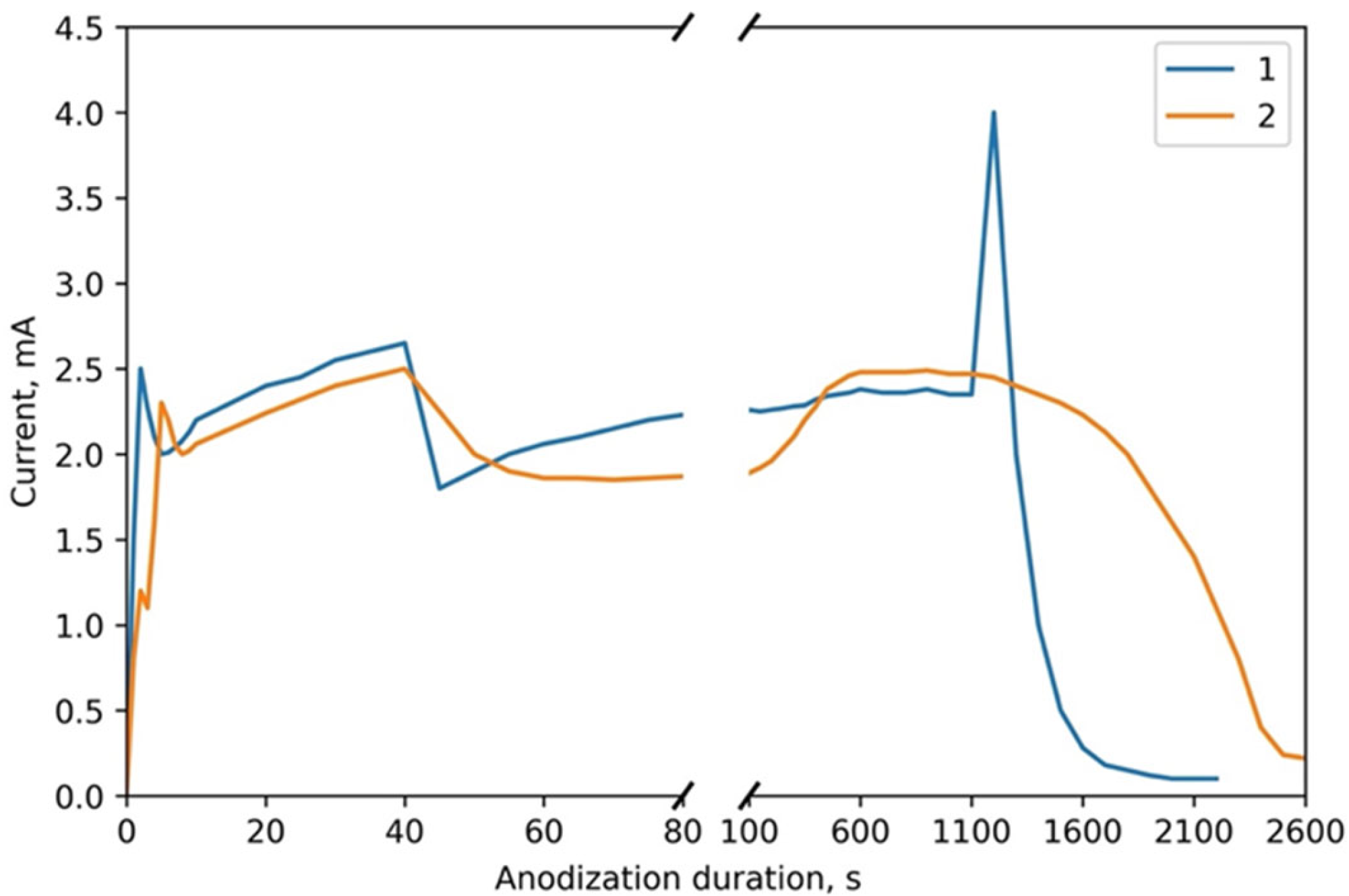
Figure 4 depicts the CVA curves of the simultaneous anodic treatment of the two-layer thin-film composition of Al (1000 nm) on Ta (400 nm) in the 4% phosphoric acid solution. Curve 1 corresponds to sample 3 of type II. Curve 2 is a comparison curve of the usual porous anodization of Al of the same thickness of 1000 nm under the same conditions. Anodization was performed in a combined regime. Curves 1 and 2 represent anodization under a voltage sweep from 0 to 80 V at a 2 V·s−1 rate and then under a constant voltage of 80 V.
Analysis of the CVA curves shows that the process consists of three characteristic stages: voltage sweep in stage I, through porous anodization of aluminum film in stage II under constant voltage, and tantalum anodization through pores in the TPAA in stage III. The transition from one layer to another can be easily seen in the CVA curves with an abrupt surge in current. In the region of the voltage sweep (stage I), the curves almost do not differ, as they correspond to the process of reaching a steady-state regime of usual porous aluminum anodization. In the region of constant voltage (stage II), the Ta sublayer assists in a more homogeneous current distribution in the sample. Only in the region of through anodization of aluminum (stage III), an abrupt current surge is observed in curves 1 and 2 of Figure 3 upon the anodization front reaching the Ta film. For the usual porous anodization of aluminum, this stage is characterized by a smooth current decrease to the value of residual current in the porous aluminum oxide formed.
The current increase upon the transition to the Ta layer may relate to the change in the thickness, morphology, and composition of the combined anodic oxide film (AOF) consisting of aluminum oxide and tantalum dioxide. The activated ion concentration increases because of the decrease in the activation energy with the transition of Ta ions into the barrier Al2O3 layer. After the transition to the Ta layer, it promotes the ion concentration increase on the metal–TPAA boundary. As a result, the ion current density through this surface increases. The Ta ion activation energy decrease upon the transition into the barrier Al2O3 layer is caused by the synthesis regime: the aluminum AOF was formed under an electric field strength higher than the value necessary for the formation of Ta2O5. Thus, the AOF resistivity decreases with the transition to Ta.
It is known that [53,54] the cation order changes if the AOF sublayer resistivity is lower than that of the upper metal AOF. It corresponds to the sublayer appearance of metal oxide on the AOF–electrolyte boundary. In our case, the upper metal AOF is a porous 800 nm-thick Al2O3 oxide. Hence, the sublayer of metal AOF is formed partially below the Al2O3 and partially inside the Al2O3 pores above the cell barrier layer as described in the model in Figure 2. The amount of Ta cations becomes higher than that of Al cations, and the oxide color changes. The light gray, transparent anodic aluminum oxide film recolors from blue to violet in the corresponding Ta oxide tone.
The formation of a dense Ta2O5 oxide layer during the next stage leads to the AOF resistance increasing and the current decreasing to its minimal value. Tantalum starts anodizing when the oxide pore bottom reaches the Al/Ta boundary. The height of the pillar structures can be increased by rising the potential applied after the TPAA formation. Such a method was used to synthesize various nanostructures on various substrates, including thin films of Ta [55], Nb [56], Ti [57,58], and TiN [59].

3.2. Morphological and Microstructural Characterization

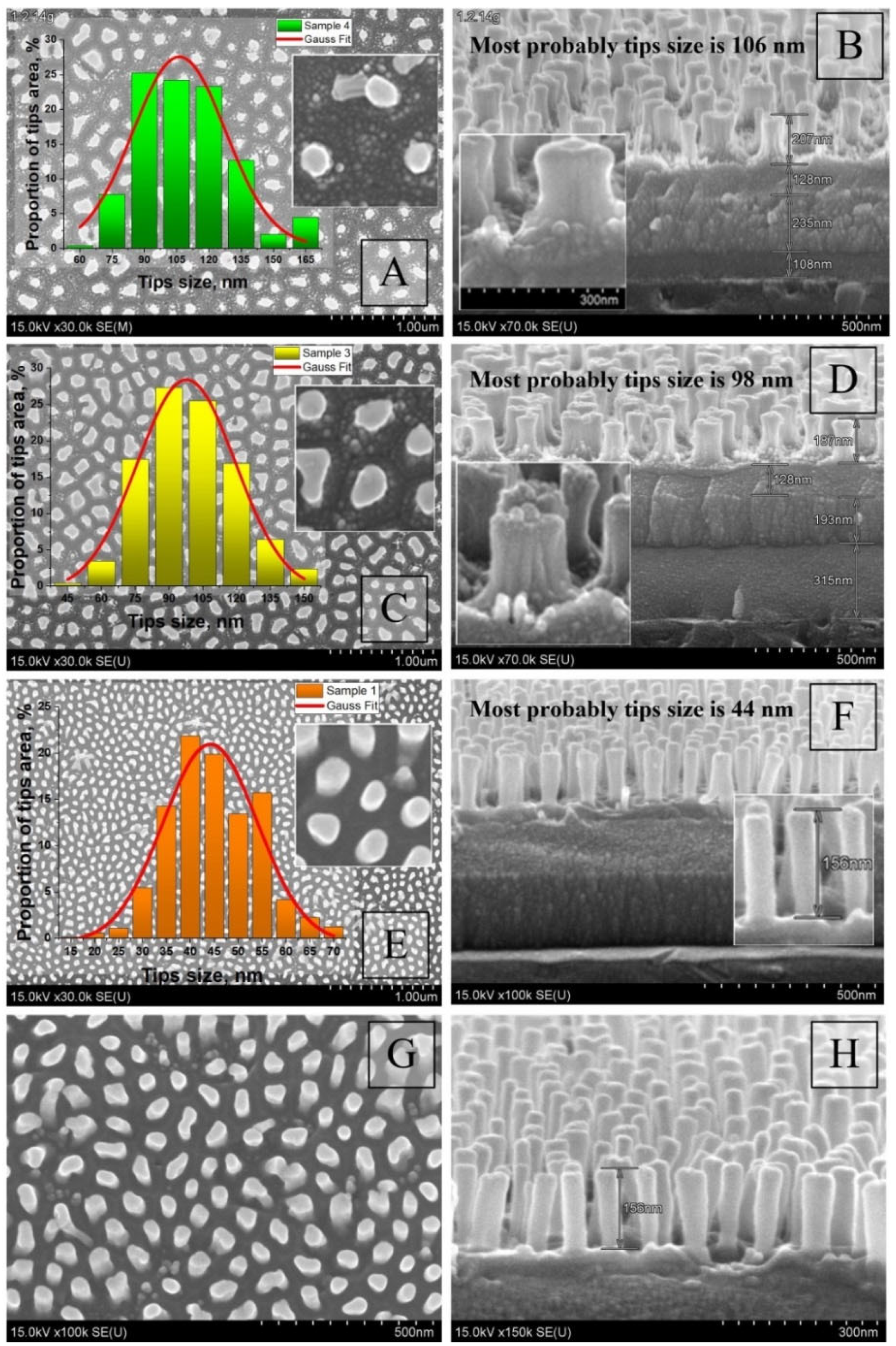
Next, we will present the results of the morphology study for various sample spots obtained at different stages of their synthesis. Figure 5 depicts the surface and cross-section SEM images and size histograms for the Ta2O5 pillars synthesized under different conditions after the Al2O3 selective etching.
The pillars have a rather homogeneous shape, with a slight widening both at the bottom and the top parts. The pillars formed under a higher UAl have a larger height and a more developed, loose basis. The images A–D for the type II samples in Figure 5 show that the pillar bottoms were growing through a range of narrow channels in the aluminum oxide pore bottoms, whereas the type I samples shown in images E–H are characterized by nearly ideal cylindrical pillar shapes with smooth sides. Hence, the result primarily depends on the electrolyte type.
Figure 6 shows the SEM images of the samples after the 90 ± 5 nm-thick nickel deposition in the synthesis fourth stage.
Figure 6 depicts the sample cross-section during the initial stage of the Ta2O5 pillar formation process. Images A and B depict a 30° chip of the sample whose formation was interrupted before the anodization reached the Al/Ta boundary. The images show the cross-section of the Al2O3 pores with Ta2O5 pillars growing through the Al2O3 barrier layer. Images C and D depict a 90° chip of the same sample. The pores have the size typical for Al anodization [60]. The insert in Figure 6B shows an enlarged image of a fragment (white circle) of the cross-section of sample 3 after reaching the Al/Ta interface and Ta2O5 pillars growing through the Al2O3 barrier layer (the cross-section was made at an angle of 30°). Inserts in Figure 6C are enlarged images of a fragment of the cross-section of the sample before and after chemical etching of the Al2O3 barrier layer (cross-section at an angle of 90°). The insert in Figure 6D represents an enlarged image of a fragment (white circle) of the cross-section of the sample after reaching the Al/Ta interface and Ta2O5 pillars growing through the Al2O3 barrier layer (cross-section at an angle of 90°).
Figure 6 also shows that Al had been completely anodized, including the residues between the oxide cells. Ta had been anodized to the depth corresponding to the anodization voltage (UAl/UTa = 80/80 V, sample 3, type II). The spherical base of the Al oxide pore cannot be seen anymore. Their bottoms had become flat. The lighter areas below the pores, highlighted by the circles in images B and C in Figure 6, correspond to anodic tantalum oxide that had grown through the aluminum oxide pore bottoms. The size of this area (the height of the Ta pillars hp) is 159 ± 5 nm. It is significantly higher than the thickness (hb) of the barrier layer for the Al oxide pore bottoms that can be calculated considering the voltage/thickness ratio for the TPAA formation in the aqueous oxalic acid electrolyte as hb = UAl × kAl = 80 V × 1.0 nm/V = 80 nm [61]. We can obtain the Ta anodization constant if we use this ratio for tantalum: kTa = hp/UTa = 159 nm/80 V ≈ 2.0 nm/V. The value is close to the value obtained in [62]. Thin light areas of Ni can be seen above the anodic tantalum oxide. It is nickel that has penetrated the pores before their shadowing, as shown in Figure 1.

3.3. Crystal Structure Analysis

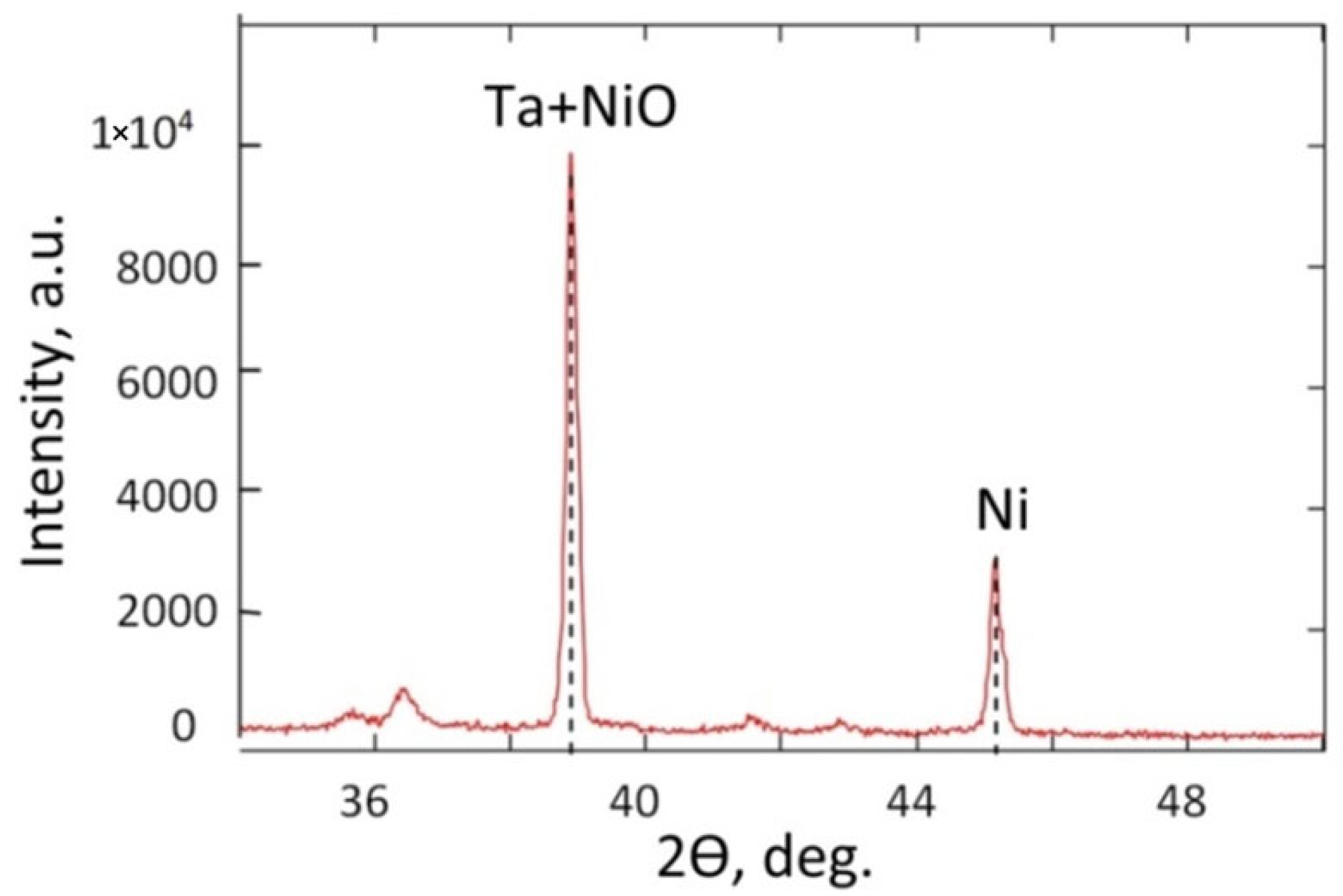
The results of the X-ray structural analysis are provided in Figure 7 and Table 3. According to the JCPDS database (Joint Committee Powder Diffraction Standards, Power Diffraction file, International Centre for Diffraction Data, Pennsylvania, PA, USA, 2001), the main Ta (2θ = 38.37°, PDF-card 25-1280) and Ni (2θ = 44.51°, PDF-card 270-989) peaks were used in the analysis. As the amorphous Ta2O5 phase, including anodic oxide, transforms into a crystalline form only after annealing at a temperature higher than 800 °C [63,64], it was not detected.
The main Ni peak at 44.51° in the XRD spectra proves the presence of metallic Ni nanoparticles. This diffraction peak corresponds to the (111) Miller index of Ni (cubic structure, space group–Fm3m–PDF-2 card 270-989) according to the JCPDS. Furthermore, the diffraction of the (111) crystal orientation of the NiO phase (PDF-2 card 47-1049) can also contribute to this peak. Nickel oxide can appear because of Ni nanoparticle thermal oxidation during the deposition and vacuum chamber cooling.

3.4. Magnetic Properties Study

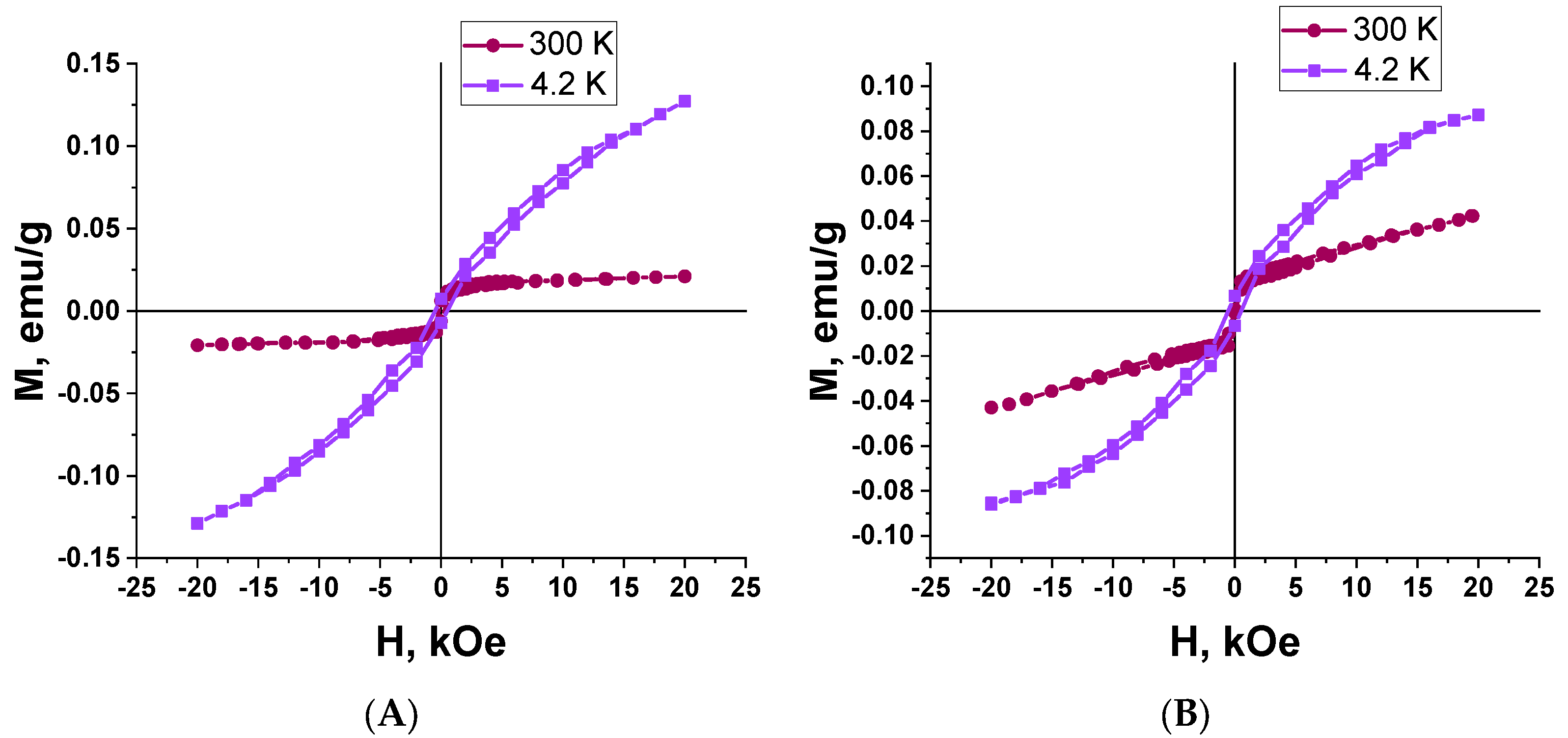
The results of the magnetic study for two types of the Ta2O5 pillars with Ni tips are shown in Figure 8 and Figure 9. The samples differ in the diameter and density of the Ta2O5 pillars. The following samples were investigated: sample 2 with an area of 2.0 × 5.0 = 10 mm2, the mass of 0.0181 g, the surface density of 0.181 mg/mm2, and the pillar diameter of (40 ± 5) nm; sample 3 with an area of 2.5 × 5.0 = 12.5 mm2, the mass of 0.0252 g, the surface density of 0.202 mg/mm2, and the pillar diameter of (100 ± 5) nm.
The perpendicular to the surface direction of the magnetic field application (out-of-plane geometry) is parallel to the direction of the Ta2O5 pillars. As the pillars are diamagnetic and nickel is situated only at their top ends, the field direction is not important, and we chose the parallel field direction.
The dependence of the magnetization on the strength of the magnetic field applied in the sample plane (the in-plane geometry, the parallel to the sample surface direction of the magnetic field application corresponds to the perpendicular to the Ta2O5 pillar axis direction) was recorded at room temperature (300 K) and 4.2 K with a magnetic field strength sweep up to 20 kOe.
Table 4 includes the calculated main magnetic parameters from the remagnetization curves.
It is important to note that the values of the saturation magnetization Ms and the remanent magnetization Mr are calculated not per mass of Ni but per the whole mass of the Ta/Ta2O5/Ni samples, including the mass of the remaining Ta and the mass of the substrate (Si/SiO2), as it is difficult to determine the mass and the volume of the metal (Ni) deposited into the TPAA pores. We assume that such a calculation of the specific magnetic properties is a valid approach because all the TPAA substrates prepared for further filling with the pillars were synthesized in the same technological cycle on identical substrates with the same thickness of the Al and Ta layers. The samples studied were taken from the same substrate. Moreover, the signal of a separately measured Si/SiO2 substrate was subtracted from the remagnetization curves to consider its contribution.
The absence of magnetic hysteresis (zero coercivity) at room temperature is characteristic for both samples. The absence of hysteresis means that upon switching off the external magnetic field, the particle magnetic moments begin oscillating freely because of thermal fluctuations. It leads to fast nanoparticle demagnetization [65]. It means that the movement of such nanoparticles can be instantaneously controlled with an external magnetic field.
The presented results show that the samples of Ta2O5 pillars with Ni tips exhibit a weak magnetic response and superparamagnetic properties at room temperature. Superparamagnetism can be seen by the magnetization curve reaching saturation at a comparatively low value of the magnetic field strength (about 1 kOe).
Hence, we can suppose that the magnetic Ni nanoparticles have a super small geometric size of about a few nanometers. In such a case, superparamagnetic properties can be expected for this composite material, as in granulated films [66].
Nickel is a ferromagnetic material. However, the hysteresis loops (Figure 8 and Figure 9) correspond to a superparamagnetic type of magnetism in the samples only. We should note that nickel prepared by different methods, including magnetron deposition, can possess superparamagnetic properties in nanosized dimensions [67]. Small 1 to 10 nm ferro- or ferrimagnetic nanoparticles become single-domain below Curie temperature. In such a state, they behave as permanent magnets, with the magnetization vectors of all their atoms directed equally [68].
We could not determine the thickness of the nickel layer on top of the Ta2O5 pillars (linear size of the nickel nanoparticles). However, results of the magnetic study suggest that they could have the size at which Ni MNPs exhibit superparamagnetic properties. The effect of ferromagnetism suppression of the nickel MNP can also be related to their oxidation, either during their magnetron deposition onto the substrates at 300 °C or during their investigation at room temperature, as the layer thickness is very low. Hence, we can also suppose that the superparamagnetism is caused by the partial oxidation of nickel crystallites during the deposition or during various room temperature complex studies (that is less probable) because of the oxygen adsorption. Molecular oxygen adsorbed at nickel crystallite boundaries can be the most probable agent leading to the appearance of superparamagnetism in partially oxidized nickel NPs and the composite as a whole, whereas the nanocrystalline nickel itself exhibits ferromagnetism. The size of the nickel nanoparticles is about 15 nm (Table 3). The size of the non-oxidized Ni NPs core can be smaller.
On the one hand, oxidation weakens the ferromagnetic properties of the Ni MNP. On the other hand, it can improve the magnetic order stabilization against thermal fluctuations in comparison with analogous systems of equiaxed magnetic nanoparticles.
The study [11] suggests using magnetic metallic nanoparticles (in particular, iron, cobalt, and nickel) as an alternative to superparamagnetic iron oxide particles in biomedicine. The authors note that besides the materials of MNPs, the most important parameter is the average particle size in combination with their narrow size distribution. To achieve the reproducibility of the properties, the synthesis should be organized so that the formation of single-domain particles with a narrow size distribution is guaranteed. Another important factor is the agglomeration of the particles that should be reduced.
Unlike the long nanowires of pure nickel and cobalt of the same diameter [69,70], the nanopillars from our samples did not group into bundles after submersion in the 4% aqueous H3PO4 solution (Figure 10). Some pillars had detached from the growth points (Al2O3 pore bottoms), but all of them had remained on the substrate.

4. Conclusions

We have shown that TPAA templates allow the preparation of aligned nanopillars. By changing the anodizing conditions of the TPAA synthesis, it is possible to change the morphology of the template and, as a result, control the morphology of the nanopillars. We proposed a model of the nanopillar film growth based on field-assisted ionic transport and confirmed it with the experimental data.
The crystal structure analysis showed that the nanopillars mainly consist of amorphous Ta2O5. The XRD spectra show the presence of metallic nickel nanoparticles (2θ = 44.51). This peak can also include a contribution from the NiO phase with a (111) crystal orientation.
The hysteresis loops of the Ta2O5 nanopillars with Ni tips are characterized by the absence of magnetic hysteresis at room temperature (zero coercivity). Thus, we can suppose that the nickel nanoparticles have a super small size, 10 nm by order of magnitude. The effect of the ferromagnetism suppression can also be related to oxidation of the nickel nanoparticles either during the magnetron deposition onto the substrates at 300 °C or during the room-temperature investigation, as the layer thickness is very low.
The Ta2O5 nanopillars with Ni tips separated from the substrate can be easily dispersed in water or ethylene glycol and used in biomedicine. We suggest using the nanostructures prepared in the next-generation nanodevices as energy storage systems [71], chemical and biochemical sensors [72], nanoelectrodes for electrochemical studies in nanosized dimensions [73], etc. Ta2O5 is biologically inert. Therefore, the Ta2O5 pillars can be used for medical diagnostics and treatment using short-range quasistationary electric fields, stimulating positive biological properties [74].
Next, we plan to investigate the possibilities of using of fabricated samples for specific applications, for example, in targeted drug delivery systems and in sensor devices (nanodiagnostics, sensitive elements of electrochemical nanosensors). In addition, 2D/3D shapes arrays of nanopillars (nanowires) have wide application possibilities. The combination of this unique structure (the 2D/3D array shapes) with uncommon magnetic, optical and transport properties can be used to develop novel functional nanomaterials for magnetic, electronic, biomedical, and optical nano-scale devices [27,55,75,76,77,78].

Author Contributions

Conceptualization, A.I.V., E.A.O. and D.I.T.; methodology, A.I.V.; software, E.K.Z. and A.A.B.; validation, I.U.R. and D.L.S.; formal analysis, S.V.T., M.V.S.; investigation, A.I.V.; E.A.O., D.I.T., T.I.Z.; resources, M.D. and M.I.S.; data curation, D.A.A.; writing—original draft preparation, A.I.V., D.I.T. and A.H.A.; writing—review and editing, A.I.V., D.I.T., A.V.T. and S.V.T.; visualization, A.I.V., D.I.T. and A.A.B.; supervision, A.I.V., D.I.T. and A.V.T.; project administration, A.I.V., M.V.S.; funding acquisition, A.I.V. All authors have read and agreed to the published version of the manuscript.

Funding

M.V.S. acknowledges financial support from the Ministry of Science and Higher Education of the Russian Federation within the framework of state support for the creation and development of World-Class Research Centers “Digital biodesign and personalized healthcare” No. 075-15-2020-926.

Data Availability Statement

The data presented in this study are available on request from thecorresponding authors.

Acknowledgments

The authors express their gratitude to Princess Nourah bint Abdulrahman University Researchers Supporting Project number (PNURSP2022R57), Princess Nourah bint Abdulrahman University, Riyadh, Saudi Arabia.

Conflicts of Interest

The authors declare that they have no known competing financial interests or personal relationships that could have appeared to influence the work reported in this paper.

References

  1. Xu, C.; Akakuru, O.U.; Zheng, J.; Wu, A. Applications of Iron Oxide-Based Magnetic Nanoparticles in the Diagnosis and Treatment of Bacterial Infections. Front. Bioeng. Biotechnol. 2019, 7, 141. [Google Scholar] [CrossRef] [PubMed]
  2. Darton, N.J.; Ionescu, A.; Llandro, J. (Eds.) Magnetic Nanoparticles in Biosensing and Medicine; Cambridge University Press: Cambridge, UK, 2019. [Google Scholar] [CrossRef]
  3. Shen, W.-Z.; Cetinel, S.; Montemagno, C. Application of biomolecular recognition via magnetic nanoparticle in nanobiotechnology. J. Nanopart. Res. 2018, 20, 130. [Google Scholar] [CrossRef]
  4. Kozlovskiy, A.L.; Kenzhina, I.E.; Zdorovets, M.V.; Saiymova, M.; Tishkevich, D.I.; Trukhanov, S.V.; Trukhanov, A.V. Synthesis, phase composition and structural and conductive properties of ferroelectric microparticles based on ATiOx (A = Ba, Ca, Sr). Ceram. Int. 2019, 45, 17236–17242. [Google Scholar] [CrossRef]
  5. Wu, K.; Su, D.; Liu, J.; Saha, R.; Wang, J.-P. Magnetic nanoparticles in nanomedicine: A review of recent advances. Nanotechnology 2019, 30, 502003. [Google Scholar] [CrossRef] [PubMed] [Green Version]
  6. Abd Elrahman, A.A.; Mansour, F.R. Targeted magnetic iron oxide nanoparticles: Preparation, functionalization and biomedical application. J. Drug Deliv. Sci. Technol. 2019, 52, 702–712. [Google Scholar] [CrossRef]
  7. Vorobjova, A.; Tishkevich, D.; Shimanovich, D.; Zdorovets, M.; Kozlovskiy, A.; Zubar, T.; Vinnik, D.; Dong, M.; Trukhanov, S.; Trukhanov, A.; et al. Electrochemical Behaviour of Ti/Al2O3/Ni Nanocomposite Material in Artificial Physiological Solution: Prospects for Biomedical Application. Nanomaterials 2020, 10, 173. [Google Scholar] [CrossRef] [Green Version]
  8. Mohammadi Ziarani, G.; Malmir, M.; Lashgari, N.; Badiei, A. The role of hollow magnetic nanoparticles in drug delivery. RSC Adv. 2019, 9, 25094–25106. [Google Scholar] [CrossRef] [Green Version]
  9. Vangijzegem, T.; Stanicki, D.; Laurent, S. Magnetic iron oxide nanoparticles for drug delivery: Applications and characteristics. Expert Opin. Drug Deliv. 2019, 16, 69–78. [Google Scholar] [CrossRef]
  10. Domagalski, J.T.; Xifre-Perez, E.; Tabrizi, M.A.; Ferre-Borrull, J.; Marsal, L.F. Magnetic nanoparticle decorated anodic alumina nanotubes for fluorescent detection of cathepsin B. J. Colloid Interface Sci. 2021, 584, 236–245. [Google Scholar] [CrossRef]
  11. Lee, J.S.; Gu, G.H.; Kim, H.; Jeong, K.S.; Bae, J.; Suh, J.S. Growth of Carbon Nanotubes on Anodic Aluminum Oxide Templates: Fabrication of a Tube-in-Tube and Linearly Joined Tube. Chem. Mater. 2001, 13, 2387–2391. [Google Scholar] [CrossRef]
  12. Vorobjova, A.; Prudnikava, A.; Shaman, Y.; Shulitski, B.; Labunov, V.; Gavrilo, S.; Belov, A.; Basaev, A. Specific Features of the Carbon Nanotubes Nucleation and Growth in the Porous Alumina Membrane. Adv. Mater. Sci. Appl. 2014, 3, 46–52. [Google Scholar] [CrossRef]
  13. Choi, J.; Sauer, G.; Nielsch, K.; Wehrspohn, R.B.; Gösele, U. Hexagonally Arranged Monodisperse Silver Nanowires with Adjustable Diameter and High Aspect Ratio. Chem. Mater. 2003, 15, 776–779. [Google Scholar] [CrossRef]
  14. Sander, M.S.; Tan, L.-S. Nanoparticle Arrays on Surfaces Fabricated Using Anodic Alumina Films as Templates. Adv. Funct. Mater. 2003, 13, 393–397. [Google Scholar] [CrossRef]
  15. Yin, A.J.; Li, J.; Jian, W.; Bennett, A.J.; Xu, J.M. Fabrication of highly ordered metallic nanowire arrays by electrodeposition. Appl. Phys. Lett. 2001, 79, 1039–1041. [Google Scholar] [CrossRef] [Green Version]
  16. Selvakumar, N.; Barshilia, H.C. Review of physical vapor deposited (PVD) spectrally selective coatings for mid- and high-temperature solar thermal applications. Sol. Energy Mater. Sol. Cells 2012, 98, 1–23. [Google Scholar] [CrossRef]
  17. Ahmadzadeh, M.; Almasi-Kashi, M. Investigations of Magnetic Properties Through Electrodeposition Current and Controlled Cu Content in Pulse Electrodeposited CoFeCu Nanowires. J. Nanostruct. 2015, 5, 257–261. [Google Scholar]
  18. Pathak, S.; Verma, R.; Kumar, P.; Singh, A.; Singhal, S.; Sharma, P.; Jain, K.; Pant, R.P.; Wang, X. Facile Synthesis, Static, and Dynamic Magnetic Characteristics of Varying Size Double-Surfactant-Coated Mesoscopic Magnetic Nanoparticles Dispersed Stable Aqueous Magnetic Fluids. Nanomaterials 2021, 11, 3009. [Google Scholar] [CrossRef]
  19. Kumar, P.; Pathak, S.; Singh, A.; Khanduri, H.; Kuldeep; Jain, K.; Tawale, J.; Wang, L.; Basheed, G.A.; Pant, R.P. Enhanced static and dynamic magnetic properties of PEG-400 coated CoFe2−xErxO4 (0.7 × 0) nanoferrites. J. Alloys Compd. 2021, 887, 161418. [Google Scholar] [CrossRef]
  20. Acharya, S.; Hill, J.P.; Ariga, K. Soft Langmuir-Blodgett Technique for Hard Nanomaterials. Adv. Mater. 2009, 21, 2959–2981. [Google Scholar] [CrossRef]
  21. Moehwald, H.; Brezesinski, G. From Langmuir Monolayers to Multilayer Films. Langmuir 2016, 32, 10445–10458. [Google Scholar] [CrossRef]
  22. Akbarzadeh, A.; Samiei, M.; Davaran, S. Magnetic nanoparticles: Preparation, physical properties, and applications in biomedicine. Nanoscale Res. Lett. 2012, 7, 144. [Google Scholar] [CrossRef] [PubMed] [Green Version]
  23. Lee, W.; Park, S.-J. Porous Anodic Aluminum Oxide: Anodization and Templated Synthesis of Functional Nanostructures. Chem. Rev. 2014, 114, 7487–7556. [Google Scholar] [CrossRef] [PubMed]
  24. Tishkevich, D.I.; Vorobjova, A.I.; Vinnik, D.A. Template Assisted Ni Nanowires Fabrication. Mater. Sci. Forum 2019, 946, 235–241. [Google Scholar] [CrossRef]
  25. Vorobjova, A.I.; Shimanovich, D.L.; Sycheva, O.A.; Ezovitova, T.I.; Tishkevich, D.I.; Trykhanov, A.V. Studying the Thermodynamic Properties of Composite Magnetic Material Based on Anodic Alumina. Russ. Microelectron. 2019, 48, 107–118. [Google Scholar] [CrossRef]
  26. Tishkevich, D.I.; Grabchikov, S.S.; Grabchikova, E.A.; Vasin, D.S.; Lastovskiy, S.B.; Yakushevich, A.S.; Vinnik, D.A.; Zubar, T.I.; Kalagin, I.V.; Mitrofanov, S.V.; et al. Modeling of paths and energy losses of high-energy ions in single-layered and multilayered materials. IOP Conf. Ser. Mater. Sci. Eng. 2020, 848, 012089. [Google Scholar] [CrossRef]
  27. Sousa, C.T.; Leitao, D.C.; Proenca, M.P.; Ventura, J.; Pereira, A.M.; Araujo, J.P. Nanoporous alumina as templates for multifunctional applications. Appl. Phys. Rev. 2014, 1, 031102. [Google Scholar] [CrossRef]
  28. Vorobjova, A.I.; Shimanovich, D.L.; Yanushkevich, K.I.; Prischepa, S.L.; Outkina, E.A. Properties of Ni and Ni–Fe nanowires electrochemically deposited into a porous alumina template. Beilstein J. Nanotechnol. 2016, 7, 1709–1717. [Google Scholar] [CrossRef] [Green Version]
  29. Zhou, Z.; Nonnenmann, S.S. Progress in Nanoporous Templates: Beyond Anodic Aluminum Oxide and Towards Functional Complex Materials. Materials 2019, 12, 2535. [Google Scholar] [CrossRef] [Green Version]
  30. Vorobjova, A.I.; Shimanovich, D.L.; Outkina, E.A.; Khodin, A.A. Highly ordered porous alumina membranes for Ni–Fe nanowires fabrication. Appl. Phys. A 2018, 124, 23. [Google Scholar] [CrossRef]
  31. Vorobjova, A.; Tishkevich, D.; Shimanovich, D.; Zubar, T.; Astapovich, K.; Kozlovskiy, A.; Zdorovets, M.; Zhaludkevich, A.; Lyakhov, D.; Michels, D.; et al. The influence of the synthesis conditions on the magnetic behaviour of the densely packed arrays of Ni nanowires in porous anodic alumina membranes. RSC Adv. 2021, 11, 3952. [Google Scholar] [CrossRef]
  32. Tishkevich, D.I.; Vorobjova, A.I.; Shimanovich, D.L.; Vinnik, D.A.; Zubar, T.I.; Kozlovskiy, A.L.; Zdorovets, M.V.; Yakimchuk, D.V.; Trukhanov, S.V.; Trukhanov, A.V. Formation and corrosion properties of Ni-based composite material in the anodic alumina porous matrix. J. Alloys Compd. 2019, 804, 139–146. [Google Scholar] [CrossRef]
  33. Tishkevich, D.I.; Vorobjova, A.I.; Vinnik, D.A. Formation and corrosion behavior of Nickel/Alumina nanocomposites. Solid State Phenom. 2020, 299, 100–106. [Google Scholar] [CrossRef]
  34. Roslyakov, I.V.; Napolskii, K.S.; Evdokimov, P.V.; Napolskiy, F.S.; Dunaev, A.V.; Eliseev, A.A.; Lukashin, A.V.; Tretyakov, Y.D. Thermal properties of anodic alumina membranes. Nanosyst. Phys. Chem. Math. 2013, 4, 120–129. [Google Scholar]
  35. Vorobjova, A.; Prudnikava, A.; Shaman, Y.; Shulitski, B.; Labunov, V.; Gavrilov, S. Carbon Nanotube-Based Composites Synthesized Using Porous Aluminum Oxide. Adv. Mater. Sci. Appl. 2014, 3, 46–52. [Google Scholar]
  36. Trukhanov, A.V.; Kozlovskiy, A.L.; Ryskulov, A.E.; Uglov, V.V.; Kislitsin, S.B.; Zdorovets, M.V.; Trukhanov, S.V.; Zubar, T.I.; Astapovich, K.A.; Tishkevich, D.I. Control of structural parameters and thermal conductivity of BeO ceramics using heavy ion irradiation and post-radiation annealing. Ceram. Int. 2019, 45, 15412–15416. [Google Scholar] [CrossRef]
  37. Poinern, G.E.J.; Le, X.T.; Hager, M.; Becker, T.; Fawcett, D. Electrochemical Synthesis, Characterisation, and Preliminary Biological Evaluation of an Anodic Aluminium Oxide Membrane with a pore size of 100 nanometres for a Potential Cell Culture Substrate. Am. J. Biomed. Eng. 2013, 3, 119–131. [Google Scholar]
  38. Vorobyova, A.I.; Sokol, V.A.; Outkina, E.A. SEM investigation of pillared microstructures formed by electrochemical anodization. Appl. Phys. A Mater. Sci. Process. 1998, 67, 487–492. [Google Scholar] [CrossRef]
  39. Vorobyova, A.I.; Outkina, E.A.; Komar, O.M. Study of metal pillar nanostructure formation with thin porous alumina template. Thin Solid Films 2013, 548, 109–117. [Google Scholar] [CrossRef]
  40. Alborzi, Z.; Hassanzadeh, A.; Golzan, M.M. Superparamagnetic Behavior of the Magnetic Hysteresis Loop in the Fe2O3@Pt Core-Shell Nanoparticles. Int. J. Nanosci. Nanotechnol. 2012, 8, 93–98. [Google Scholar]
  41. Liu, H.; Wu, J.; Min, J.H.; Hou, P.; Song, A.-Y.; Kim, Y.K. Non-aqueous synthesis of water-dispersible Fe3O4–Ca3(PO4)2 core–shell nanoparticles. Nanotechnology 2011, 22, 055701. [Google Scholar] [CrossRef]
  42. Hirotaka, S.; Takayuki, H. Fabrication of Magnetic Nanodot Arrays for Patterned Magnetic Recording Media. J. Nanosci. Nanotechnol. 2007, 7, 225–231. [Google Scholar]
  43. Yasui, K.; Nishio, K.; Masuda, H. Fabrication of Nanocomposites by Filling Nanoholes in Highly Ordered Anodic Porous Alumina by Vacuum Deposition of Metal. Jpn. J. Appl. Phys. 2005, 44, L1181–L1183. [Google Scholar] [CrossRef]
  44. Kim, M.J.; Kim, Y.W.; Lee, J.S.; Yoo, J.-B.; Park, C.Y. Magnetic Properties of Ni Nanostructures Fabricated Using Anodic Aluminum Oxide Templates. J. Korean Phys. Soc. 2005, 47, 313–317. [Google Scholar]
  45. Liu, K.; Nogue, J.; Leighton, C.; Masuda, H.; Nishio, K.; Roshchin, I.V.; Schuller, I.K. Fabrication and thermal stability of arrays of Fe nanodots. Appl. Phys. Lett. 2002, 81, 4434–4436. [Google Scholar] [CrossRef] [Green Version]
  46. Xu, Q.; Meng, G.; Han, F. Porous AAO template-assisted rational synthesis of large-scale 1D hybrid and hierarchically branched nanoarchitectures. Prog. Mater. Sci. 2018, 95, 243–285. [Google Scholar] [CrossRef]
  47. Ivanov, Y.P.; Alfadhel, A.; Alnassar, M.; Perez, J.E.; Vazquez, M.; Chuvilin, A.; Kosel, J. Tunable magnetic nanowires for biomedical and harsh environment applications. Sci. Rep. 2016, 6, 24189. [Google Scholar] [CrossRef] [Green Version]
  48. Moreno, J.A.; Bran, C.; Vazquez, M.; Kosel, J. Cylindrical Magnetic Nanowires Applications. IEEE Trans. Magn. 2021, 57, 1–17. [Google Scholar] [CrossRef]
  49. Tishkevich, D.I.; Vorobjova, A.I.; Trukhanov, A.V. Thermal stability of nano-crystalline nickel electrodeposited into porous alumina. Solid State Phenom. 2020, 299, 281–286. [Google Scholar] [CrossRef]
  50. Lei, Y.; Cai, W.; Wilde, G. Highly ordered nanostructures with tunable size, shape and properties: A new way to surface nano-patterning using ultra-thin alumina masks. Prog. Mater. Sci. 2007, 52, 465–539. [Google Scholar] [CrossRef]
  51. Tishkevich, D.; Grabchikov, S.; Zubar, T.; Vasin, D.; Trukhanov, S.; Vorobjova, A.; Yakimchuk, D.; Kozlovskiy, A.; Zdorovets, M.; Giniyatova, S.; et al. Early-Stage Growth Mechanism and Synthesis Conditions-Dependent Morphology of Nanocrystalline Bi Films Electrodeposited from Perchlorate Electrolyte. Nanomaterials 2020, 10, 1245. [Google Scholar] [CrossRef]
  52. Slimani, Y.; Algarou, N.A.; Almessiere, M.A.; Sadaqat, A.; Vakhitov, M.G.; Klygach, D.S.; Tishkevich, D.I.; Trukhanov, A.V.; Guner, S.; Hakeem, A.S.; et al. Fabrication of exchange coupled hard/soft magnetic nanocomposites: Correlation between composition, magnetic, optical and microwave properties. Arab. J. Chem. 2021, 14, 102992. [Google Scholar] [CrossRef]
  53. Pringle, J.P.S. The anodic oxidation of superimposed metallic layers: Theory. Electrochim. Acta 1980, 25, 1423–1437. [Google Scholar] [CrossRef]
  54. Pringle, J.P.S. Transport Numbers of Metal and Oxygen during the Anodic Oxidation of Tantalum. J. Electrochem. Soc. 1973, 120, 398. [Google Scholar] [CrossRef]
  55. Vorobyova, A.I.; Outkina, E.A. Study of pillar microstructure formation with anodic oxides. Thin Solid Films 1998, 324, 1–10. [Google Scholar] [CrossRef]
  56. Mozalev, A.; Sakairi, M.; Saeki, I.; Takahashi, H. Nucleation and growth of the nanostructured anodic oxides on tantalum and niobium under the porous alumina film. Electrochim. Acta 2003, 48, 3155–3170. [Google Scholar] [CrossRef]
  57. Sjöström, T.; Fox, N.; Su, B. A study on the formation of titania nanopillars during porous anodic alumina through-mask anodization of Ti substrates. Electrochim. Acta 2010, 56, 203–210. [Google Scholar] [CrossRef]
  58. Chu, S.-Z.; Inoue, S.; Wada, K.; Hishita, S.; Kurashima, K. Self-Organized Nanoporous Anodic Titania Films and Ordered Titania Nanodots/Nanorods on Glass. Adv. Func. Mater. 2005, 15, 1343–1349. [Google Scholar] [CrossRef]
  59. Chen, P.-L.; Kuo, C.-T.; Tsai, T.-G.; Wu, B.-W.; Hsu, C.-C.; Pan, F.-M. Self-organized titanium oxide nanodot arrays by electrochemical anodization. Appl. Phys. Lett. 2003, 82, 2796–2798. [Google Scholar] [CrossRef] [Green Version]
  60. Li, A.P.; Müller, F.; Birner, A.; Nielsch, K.; Gösele, U. Hexagonal pore arrays with a 50–420 nm interpore distance formed by self-organization in anodic alumina. J. Appl. Phys. 1998, 84, 6023–6026. [Google Scholar] [CrossRef] [Green Version]
  61. Nielsch, K.; Choi, J.; Schwirn, K.; Wehrspohn, R.B.; Gösele, U. Self-ordering Regimes of Porous Alumina: The 10 Porosity Rule. Nano Lett. 2002, 2, 677–680. [Google Scholar] [CrossRef]
  62. Lu, Q.; Mato, S.; Skeldon, P.; Thompson, G.E.; Masheder, D.; Habazaki, H.; Shimizu, K. Anodic film growth on tantalum in dilute phosphoric acid solution at 20 and 85 °C. Electrochim. Acta 2002, 47, 2761–2767. [Google Scholar] [CrossRef]
  63. Ren, W.; Yang, G.-D.; Feng, A.-L.; Miao, R.-X.; Xia, J.-B.; Wang, Y.-G. Annealing effects on the optical and electrochemical properties of tantalum pentoxide films. J. Adv. Ceram. 2021, 10, 704–713. [Google Scholar] [CrossRef]
  64. Bright, T.J.; Watjen, J.I.; Zhang, Z.M.; Muratore, C.; Voevodin, A.A.; Koukis, D.I.; Tanner, D.B.; Arenas, D.J. Infrared optical properties of amorphous and nanocrystalline Ta2O5 thin films. J. Appl. Phys. 2013, 114, 083515. [Google Scholar] [CrossRef]
  65. Zubar, T.I.; Panina, L.V.; Kovaleva, N.N.; Sharko, S.A.; Tishkevich, D.I.; Vinnik, D.A.; Gudkova, S.A.; Trukhanova, E.L.; Trofimov, E.A.; Chizhik, S.A.; et al. Anomalies in growth of electrodeposited Ni-Fe nanogranular films. CrystEngComm 2019, 21, 2464. [Google Scholar] [CrossRef] [Green Version]
  66. Tochitskii, T.A.; Jones, G.A.; Blythe, H.J.; Fedosyuk, V.M.; Castro, J. Fine structure and possible growth mechanisms of some electrodeposited CuCo granular films. J. Magn. Magn. Mater. 2001, 224, 221–232. [Google Scholar] [CrossRef]
  67. Sorensen, C.M. Magnetism. In Nanoscale Materials in Chemistry; Klabunde, K.J., Ed.; John Wiley & Sons, Inc.: New York, NY, USA, 2001; pp. 169–221. [Google Scholar] [CrossRef]
  68. Fedosyuk, V.M. Nanogranular electrodeposited magnetic cobalt alloys. In Encyclopedia of Nanoscience and Nanotechnology; Nalwa, H.S., Ed.; American Scientific Publishers: Valencia, CA, USA, 2003; pp. 1–24. [Google Scholar]
  69. Prida, V.M.; Pirota, K.R.; Navas, D.; Asenjo, A.; Hernández-Vélez, M.; Vázquez, M. Self-Organized Magnetic Nanowire Arrays Based on Alumina and Titania Templates. J. Nanosci. Nanotechnol. 2007, 7, 272–285. [Google Scholar] [CrossRef]
  70. Tishkevich, D.; Vorobjova, A.; Shimanovich, D.; Kaniukov, E.; Kozlovskiy, A.; Zdorovets, M.; Vinnik, D.; Turutin, A.; Kubasov, I.; Kislyuk, A.; et al. Magnetic Properties of the Densely Packed Ultra-Long Ni Nanowires Encapsulated in Alumina Membrane. Nanomaterials 2021, 11, 1775. [Google Scholar] [CrossRef]
  71. Banerjee, P.; Perez, I.; Henn-Lecordier, L.; Lee, S.B.; Rubloff, G.W. Nanotubular metal–insulator–metal capacitor arrays for energy storage. Nat. Nanotechnol. 2009, 4, 292–296. [Google Scholar] [CrossRef]
  72. Yogeswaran, U.; Chen, S.-M. A Review on the Electrochemical Sensors and Biosensors Composed of Nanowires as Sensing Material. Sensors 2008, 8, 290–313. [Google Scholar] [CrossRef] [Green Version]
  73. Santos, A.; Vojkuvka, L.; Pallarés, J.; Ferré-Borrull, J.; Marsal, L. Cobalt and Nickel Nanopillars on Aluminium Substrates by Direct Current Electrodeposition Process. Nanoscale Res. Lett. 2009, 4, 1021. [Google Scholar] [CrossRef] [Green Version]
  74. Donkov, N.; Zykova, A.; Safonov, V.; Matveev, E. Modern Methods of Ta2O5 coatings deposition for biomedical applications. Probl. At. Sci. Technol. 2009, 1, 153–155. [Google Scholar]
  75. Um, J.; Park, J.J.; Flatau, A.; Zhou, W.; Zhang, Y.; Franklin, R.; Reddy, K.S.M.; Tan, L.; Sharma, A.; Sung, S.-Y.; et al. Template-assisted electrodeposited magnetic nanowires and their properties for applications. In Magnetic Nano-Microwires, 2nd ed.; Elsevier: Amsterdam, The Netherlands, 2020; pp. 675–695. [Google Scholar] [CrossRef]
  76. Shoso, S.; Takafumi, Y.; Hironori, M.; Seiji, A.; Yasuhiko, A.; Sumio, N.; Sumio, N.; Tomomi, Y.; Kennichi, S. Fabrication of ultra high density magnetic recording media using self-organized porous alumina nanohole array. Sci. Technol. Rep. Kansai Univ. 2009, 51, 1–7. [Google Scholar]
  77. Kazarkin, B.A.; Stsiapanau, A.A.; Belyaev, V.V.; Chausov, D.N. New applications of nanostructured materials in the prospect electronic devices. Int. Sci. J. Ind. 4.0 2017, 2, 272–274. [Google Scholar]
  78. Wang, S.K.; Chen, M.; Wang, H.; Li, G.; Chen, J.; Liu, L.; Xu, Y.; Jian, C.; Meng, X.; Zheng, S.; et al. Controllable synthesis of nickel nanowires and its application in high sensitivity, stretchable strain sensor for body motion sensing. J. Mater. Chem. C. 2018, 6, 4737–4745. [Google Scholar] [CrossRef]
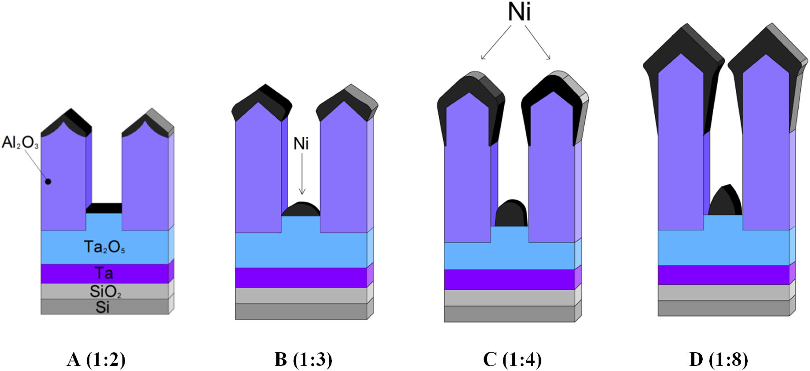
Figure 1. Schematic representation of possible shadowing effects of the Ni coating deposited onto a thin porous anodic film. The thickness of the Ni coating increases and the ratio of the pore diameter to the oxide thickness decreases from (AD) [50].
Nanomaterials 12 01344 g001
Figure 2. Schematic diagram of the main steps for nanopillars forming from Al/Ta metal sputter-deposited layers on a Si substrate: (A) porous anodizing of the Al film to a certain depth; (B) porous anodization of the Al film to Ta film; (C) anodization of a Ta layer at the Al anodizing voltage (UAl); (D) formation of Ta2O5 pillars at Ta anodizing voltage (UTa).
Nanomaterials 12 01344 g002
Figure 3. CVA curves of the simultaneous anodic treatment of the two-layer thin-film composition of Al (1000 nm) on Ta (400 nm) for type I samples: 1—sample No. 1; 2—sample No. 2; 3—Al only (1000 nm).
Nanomaterials 12 01344 g003
Figure 4. CVA curves of the simultaneous anodic treatment of the two-layer thin-film composition of Al (100 nm) on Ta (400 nm) for type II samples: 1—sample No. 3; 2—Al only (1000 nm).
Nanomaterials 12 01344 g004
Figure 5. Surface and cross-section SEM images and size histograms for the Ta2O5 pillars after the Al2O3 selective etching: (A,B)—sample 4 of type II; (C,D)—sample 3 of type II; (EH)—sample 1 of type I.
Nanomaterials 12 01344 g005
Figure 6. Cross-section SEM images of sample 3 (Si/SiO2/Ta/Ta2O5/TPAA/Ni) after the first stage of double-layer Al/Ta composition anodization and Ni deposition.
Nanomaterials 12 01344 g006
Figure 7. XRD spectrum of the experimental sample of the Ta/Ta2O5 pillars with Ni tips.
Nanomaterials 12 01344 g007
Figure 8. Comparison of the hysteresis loops for two samples of Ta2O5 pillars with Ni tips at different temperatures: (A)—sample 2 (type I), (B)—sample 3 (type II).
Nanomaterials 12 01344 g008
Figure 9. Comparison of the hysteresis loops for two samples of the Ta2O5 pillars with Ni tips at 300 K.
Nanomaterials 12 01344 g009
Figure 10. SEM image of the test sample with Ta2O5/Ni pillars after submersion in a diluted aqueous solution of phosphoric acid (sample 2, type I).
Nanomaterials 12 01344 g010
Table 1. The deposition parameters for the tantalum and aluminum thin films.
Deposition Process ParametersTantalumAluminum
Residual gas pressure, Pa1.3 × 10−31.4 × 10⁻⁴
Substrate temperature, K523423
Accelerating voltage, kV88
Beam current, A0.41.2
Deposition rate, nm·s−11.0 ± 0.25.0 ± 0.5
Thickness, nm450 ± 50(1000–2000) ± 50
Table 2. Parameters of the TPAA samples and their preparation procedures.
Sample TypeSample No.ElectrolyteVoltage,
UAl, V
Voltage, UTa, VPillar (Pore) Diameter,
nm
Interpore
Distance,
nm
Pillar Height,
nm
Pillar Density,
per cm2
type I1C2H2O4404040 ± 5100 ± 5150 ± 1010 × 109
27040 ± 5100 ± 5160 ± 1010 × 109
type II3H3PO48080100 ± 5200 ± 5180 ± 103 × 109
4 90100 ± 5210 ± 5220 ± 102 × 109
Table 3. Results of the X-ray structural analysis of the Ta/Ta2O5/Ni experimental samples. The values in parentheses in the 2θ column are the corresponding angles from the JCPDS database.
MaterialCrystallographic Direction2θ, deg.I, %Coherence Region Size L, nm
β-Ta(002)36.4 (35.61)
JCPDS (25-1280)
α-Ta(110)38.37 (38.4)
JCPDS (25-1280)
100-
Ni(111) face-centered cubic (fcc) structure44.15 (44.51)
JCPDS PDF-card (270-989)
3213
NiO(111)37.8 (38.33)
JCPDS (47-1049)
--
Table 4. The results of the magnetic measurements for the samples of the Ta2O5 pillars with Ni tips.
TypeSampleTemperature, KHc, kOeMr, emu/gMs, emu/gMr/Ms
I24.25110.0070.1270.06
300----
II34.25250.0070.0870.08
300----
Publisher’s Note: MDPI stays neutral with regard to jurisdictional claims in published maps and institutional affiliations.