Article

Colloidal Processing of Mn3O4-Carbon Nanotube Nanocomposite Electrodes for Supercapacitors

Department of Materials Science and Engineering, McMaster University, Hamilton, ON L8S 4L7, Canada
*
Author to whom correspondence should be addressed.
Nanomaterials 2022, 12(5), 803; https://doi.org/10.3390/nano12050803
Submission received: 8 February 2022 / Revised: 22 February 2022 / Accepted: 24 February 2022 / Published: 26 February 2022
(This article belongs to the Section Nanocomposite Materials)

Abstract

:
This investigation addresses the challenges in the development of efficient nanostructured Mn3O4 cathodes for supercapacitors. A high areal capacitance and the ability to avoid a time-consuming activation procedure for electrodes with high active mass loading of 40 mg cm−2 are reported. This facilitates practical applications of Mn3O4 based electrodes. The highest capacitance of 6.11 F cm−2 (153 F g−1) is obtained from cyclic voltammetry at a scan rate of 2 mV s−1 and 6.07 F cm−2 (151.9 F g−1) from the chronopotentiometry at a current density of 3 mA cm−2 in a potential window of 0.9 V in a neutral Na2SO4 electrolyte. The new approach is based on the application of rhamnolipids (RL) as a capping agent for the synthesis of Mn3O4 particles and a co-dispersant for Mn3O4 and carbon nanotubes, which are used as conductive additives. The size and shape of the Mn3O4 particles are influenced by RL. The enhanced performance of the electrodes is linked to the chemical structure and properties of RL molecules, which exert influence on Mn3O4 particle size and shape during synthesis, reduce agglomeration, facilitate RL adsorption on Mn3O4 and carbon nanotubes, and influence their co-dispersion and mixing at the nanometric scale.

1. Introduction

Colloidal methods are widely used for the fabrication of advanced nanomaterials and nanocomposites [1,2,3]. The use of surfactants for colloidal nanofabrication allows efficient control of particle size and prevention of their agglomeration [4,5,6,7]. Of particular interest is the use of surfactants for the fabrication of nanocomposite electrodes for energy storage in supercapacitors. It was found that surfactants facilitate the fabrication of nanoparticles of inorganic charge storage materials with small particle size and prevent their agglomeration [8]. Significant interest has been generated in co-dispersants for efficient mixing of the charge storage materials with conductive additives [8]. The use of such co-dispersants for colloidal fabrication allowed for significant improvement of electrochemical performance of supercapacitors and batteries for practical applications [8,9]. Electrode porosity is an important factor controlling electrochemical performance [10,11,12]. High porosity facilitates good electrolyte access to the active material. Significant attention focused on the development of electrodes with hierarchical porosity [13,14], which allows for superior electrode performance. Advanced techniques were developed for the fabrication of activated carbon, graphene, carbon fiber, MXene, metal oxide and hydroxide electrodes with high porosity [15,16,17,18,19].
This research was motivated by the need in efficient capping agents and dispersants for the fabrication of advanced electrodes for supercapacitors. It has previously been shown that nanocomposites, based on Mn3O4 are promising materials for cathodes of asymmetric supercapacitors [8]. However, challenges in Mn3O4 applications are related to the development of efficient electrodes with commercially important high active mass [8]. The specific capacitance decreased with increasing of the active mass [8]. Moreover, the application of Mn3O4 electrodes with high active mass requires time-consuming activation procedures [20,21,22], which must be avoided for practical applications. It was found that first charge-discharge cycles of Mn3O4 electrodes showed low capacitance and activation cycling procedure was necessary in order to activate material and achieve high capacitance. Such activation procedures resulted in significant capacitance increase [20,22,23,24]. Several XPS studies revealed oxidation of Mn2+ and Mn3+ ions on the Mn3O4 particle surface during cycling and linked this process to the increasing capacitance [20,21,22,25]. The challenges related to Mn3O4 applications can be addressed using advanced capping agents for the Mn3O4 synthesis and co-dispersants for Mn3O4 and conductive additives.
The search for advanced dispersants for colloidal nanotechnology of energy storage materials has generated our interest in rhamnolipids (RL). RL are natural biosurfactants, which offer many benefits since their critical micelle concentration is 10–100 times lower than that of traditional chemical surfactants [26]. RL can solubilize highly hydrophobic organic molecules in aqueous solutions [27]. RL are biocompatible, chemically stable and low cost biosurfactants [26], which have many applications in environmental field, food industry, and biotechnology [28,29,30]. RL are used for prevention of marine oil pollution, removing oil from sand [31] and various applications in agriculture [32,33], laundry products and medicine [26]. RL exhibit valuable antimicrobial and anticancer properties [33,34]. Significant interest has been generated in applications of RL as dispersants for BaTiO3 [35], alumina [36,37], zirconia [38], and hematite [39] particles in aqueous suspensions. RL were used as capping agents for synthesis of ZnS [40], NiO [41], and Ag [42] nanoparticles.
The goal of this investigation was the fabrication of Mn3O4-carbon nanotube composites for cathodes of asymmetric supercapacitors. The use of carbon nanotubes as conductive additives was critically important due to the low electronic conductivity of Mn3O4 [8,43]. For the first time we report the application of RL as a capping agent for the synthesis of Mn3O4 nanoparticles. The results presented below indicated that the shape and size of the synthesized Mn3O4 particles is influenced by RL. Moreover, RL prevent agglomeration of Mn3O4 particles during synthesis. Another important finding was good co-dispersion of Mn3O4 and carbon nanotubes by RL, which adsorbed on both materials and facilitated their electrostatic dispersion. It is in this regard that various commercial surfactants are efficient in dispersion of only one type of material, such as inorganic particles or carbon materials [44,45]. The ability of efficient co-dispersion of Mn3O4 and carbon nanotubes by RL allowed for their efficient mixing and facilitated the fabrication of nanocomposite electrodes with high capacitance. Moreover, the time-consuming activation procedure for the fabrication of Mn3O4 electrodes can be avoided. The results of this investigation indicated that Mn3O4-carbon nanotube composites are promising for practical applications for energy storage in cathodes of asymmetric supercapacitors.

2. Materials and Methods

RL, ethanol, Mn(NO3)2·4H2O, NaOH, Na2SO4, poly(vinyl butyral-co-vinyl alcohol-co-vinyl acetate) (PVB, MilliporeSigma, Oakville, ON, Canada), and multiwalled carbon nanotubes (MWCNT, ID 4 nm, OD 13 nm, length 1–2 μm, Bayer, Leverkusen, Germany) were used as starting materials. The as-received MWCNT formed large agglomerates with a typical diameter of 0.5 mm. PVB is advanced co-polymer binder [46,47] designed for colloidal processing of inorganic particles. Polyvinyl alcohol functional groups facilitate PVB adsorption on inorganic particles by formation of hydrogen bonds with hydroxyl groups on the particle surface [46,47]. Butyral segments are directed toward the organic solvent, providing steric stabilization [46,47].
Mn3O4 nanoparticles were prepared by a modified chemical precipitation method [23] and mixed with MWCNT. In method 1, a solution of 330 mg of Mn(NO3)2·4H2O in 20 mL of DI water was prepared and then the pH of the solution was increased to pH = 10 with aqueous NaOH for the Mn3O4 synthesis. The synthesis was performed without the use of RL. In this method, RL were used as co-dispersants for Mn3O4 and MWCNT. As-prepared Mn3O4 was mixed in the aqueous phase with MWCNT and then RL were added. The mass ratio of Mn3O4:CNT:RL was 4:1:1.
In method 2, RL were used as a capping agent for Mn3O4 synthesis and a co-dispersant for Mn3O4 and MWCNT. A solution of 330 mg of Mn(NO3)2·4H2O in DI water was prepared and RL were added as a capping agent for the synthesis of Mn3O4 nanoparticles to achieve Mn3O4:RL ratio of 4:2. The pH of the solution was increased to pH = 10 with aqueous NaOH for the Mn3O4 synthesis and then MWCNT were added to Mn3O4 in the aqueous phase. The mass ratio of Mn3O4:CNT:RL was 4:1:2. Additional experiments were performed for mass ratio of Mn3O4:CNT:RL = 4:1:1 (Figures S1–S4). The mixtures of Mn3O4 with MWCNT, containing RL and prepared by both methods were ultrasonicated for achieving improved dispersion and mixing, and then washed and dried. In both methods the Mn(NO3)2 solutions were stirred for 30 min before adding NaOH. The amount of added NaOH was the same in both methods. Obtained powders were used for the fabrication of electrodes using slurries of Mn3O4 and MWCNT in ethanol, containing PVB as a binder. The PVB binder content was 3% of the total mass of Mn3O4 and MWCNT. The slurries were used for impregnation of commercial Ni foam (Vale, Toronto, ON, Canada) current collectors. The total mass of impregnated material after drying was 40 mg cm−2.
Microstructure investigations were performed using transmission electron microscopy (TEM, Talos 200X microscope, Thermo Scientific, Waltham, MA, USA) and scanning electron microscopy (SEM, JEOL, JSM-7000F microscope, Tokyo, Japan) methods. X-ray diffraction (XRD) analysis (diffractometer Bruker D8, Coventry, UK) was performed using Cu-Kα radiation at the rate of 0.01 degrees per second. Fourier Transform Infrared Spectroscopy (FTIR) studies were performed using a Bruker Vertex 70 spectrometer (Billerica, MA, USA). XPS analysis was performed using Quantera II Scanning XPS instrument (PHI, Chanhassen, MN, USA). Electrochemical studies were performed in aqueous 0.5 M Na2SO4 electrolyte using PARSTAT 2273 potentiostat (AMETEK, Berwyn, PA, USA) for cyclic voltammetry (CV) and electrochemical impedance spectroscopy (EIS). A BioLogic VMP 300 potentiostat was used for galvanostatic charge-discharge (GCD) investigations (BioLogic, Claix, France). Testing was performed using a 3-electrode electrochemical cell containing a working electrode (impregnated Ni foam), counter-electrode (Pt mesh), and a reference electrode (SCE, saturated calomel electrode). The capacitive properties of electrode material were presented in gravimetric (Cm, F g−1) and areal (CS, F cm−2) capacitance forms. Capacitances Cm and CS were calculated from the CV, EIS and GCD data as it was described in reference [8]. The capacitances calculated from the CV and GCD data represented integral capacitances measured in a potential window of 0–0.9 V versus SCE. The capacitances calculated from the EIS data represented differential capacitances measured at an open circuit potential at voltage amplitude of 5 mV. CV testing procedures (TP) involved obtaining CV at scan rates of 2, 5, 10, 20, 50 and 100 mV s−1. EIS measurements were performed after each TP. GCD measurements were performed after the last TP.

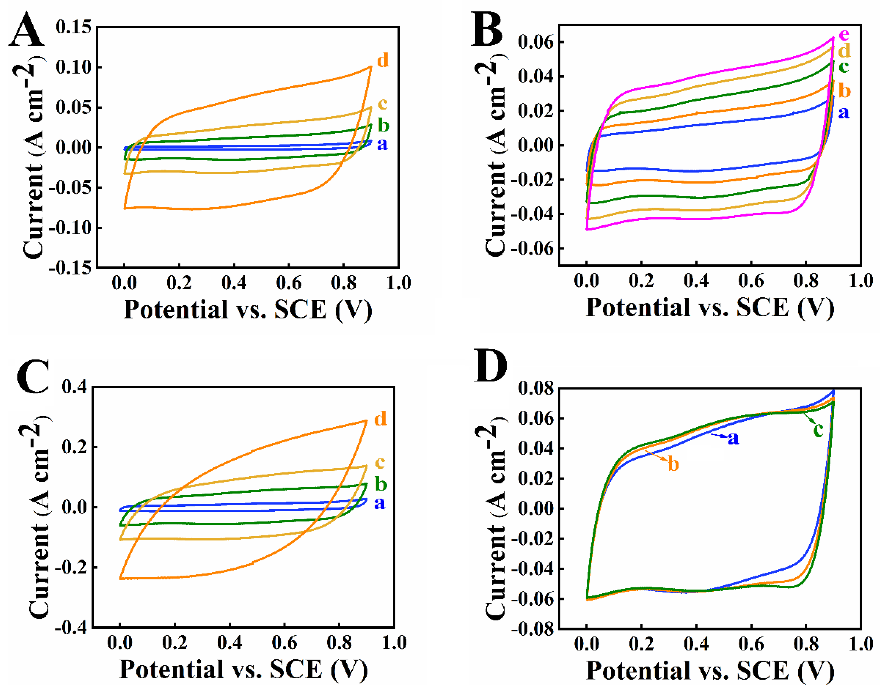
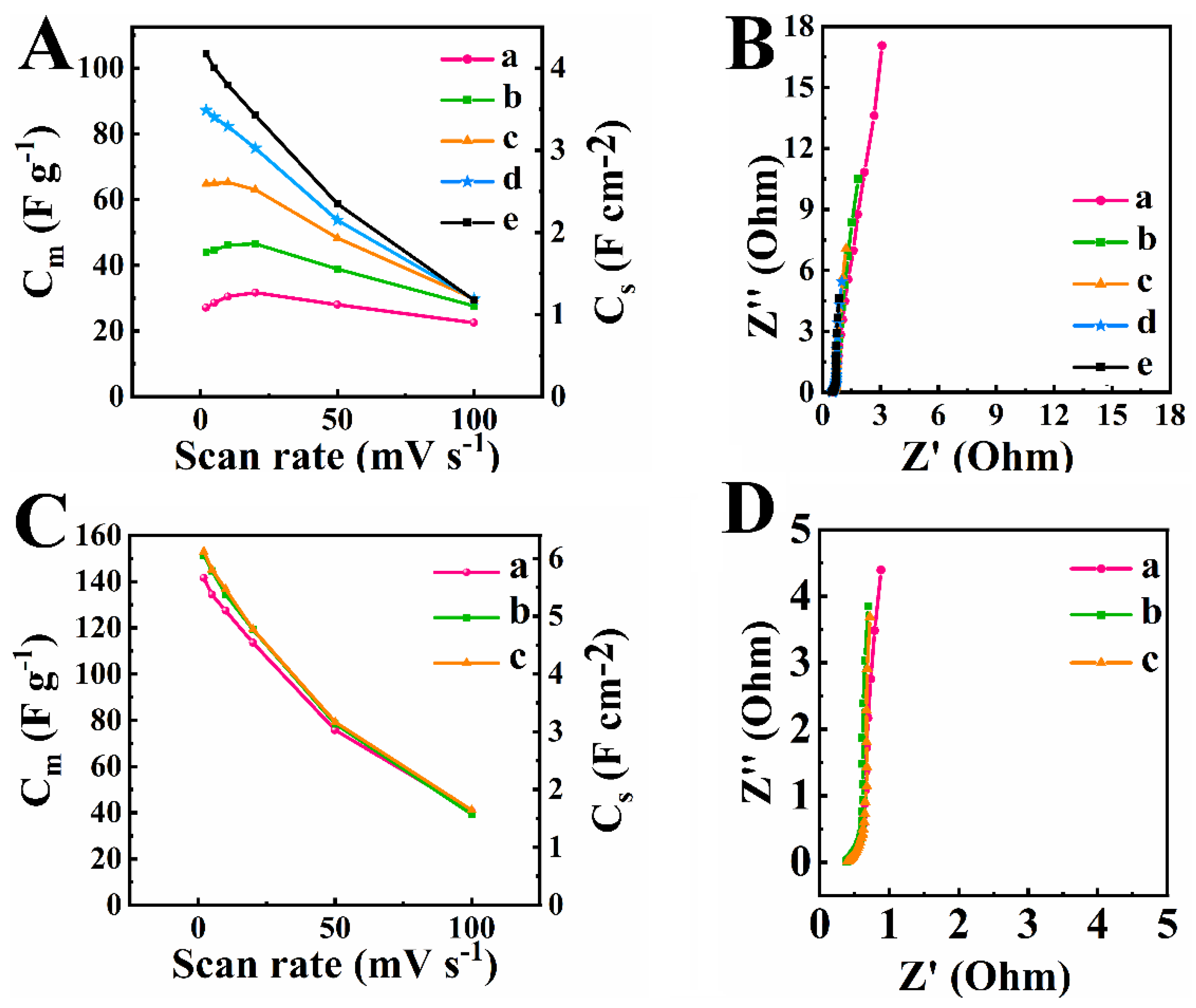
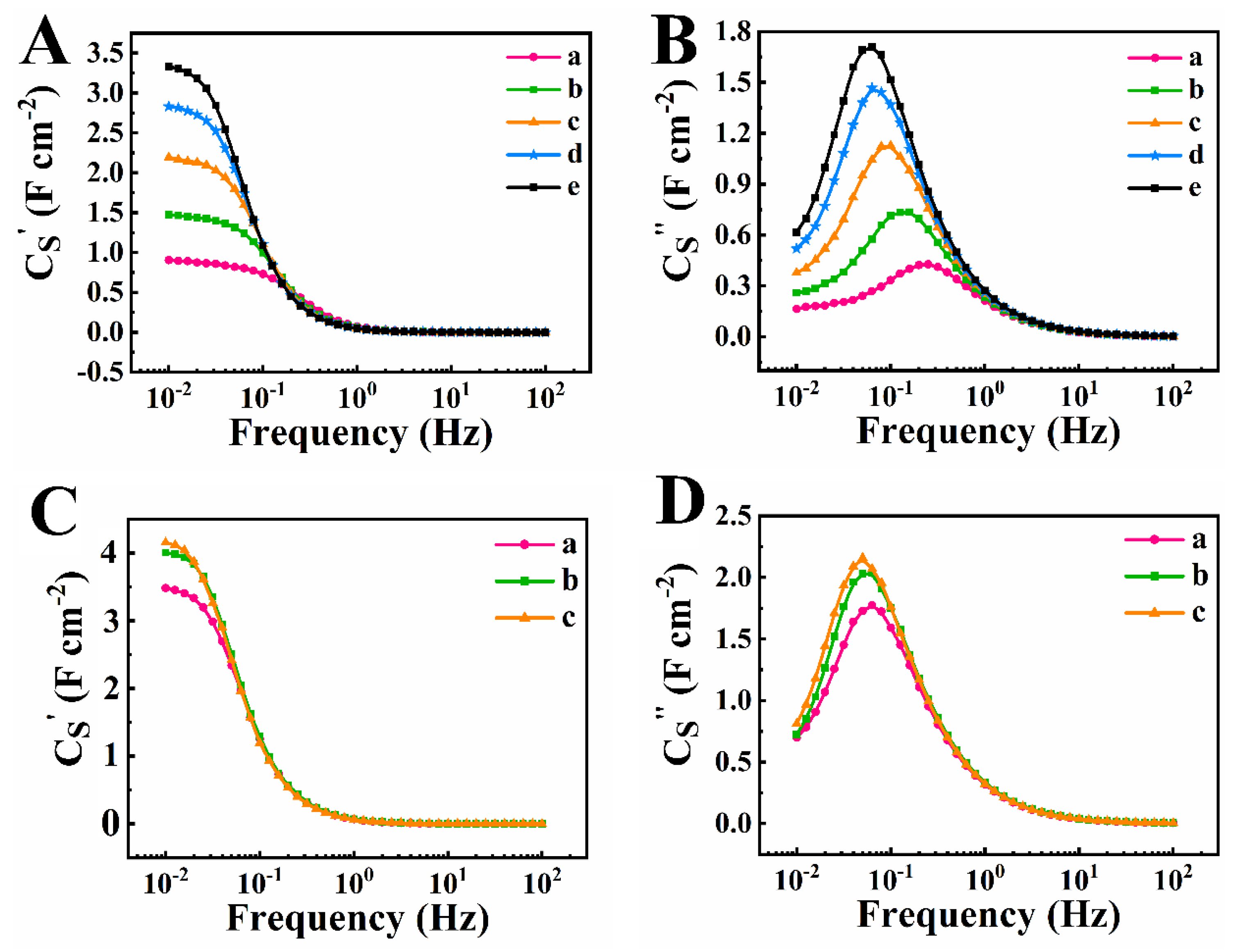
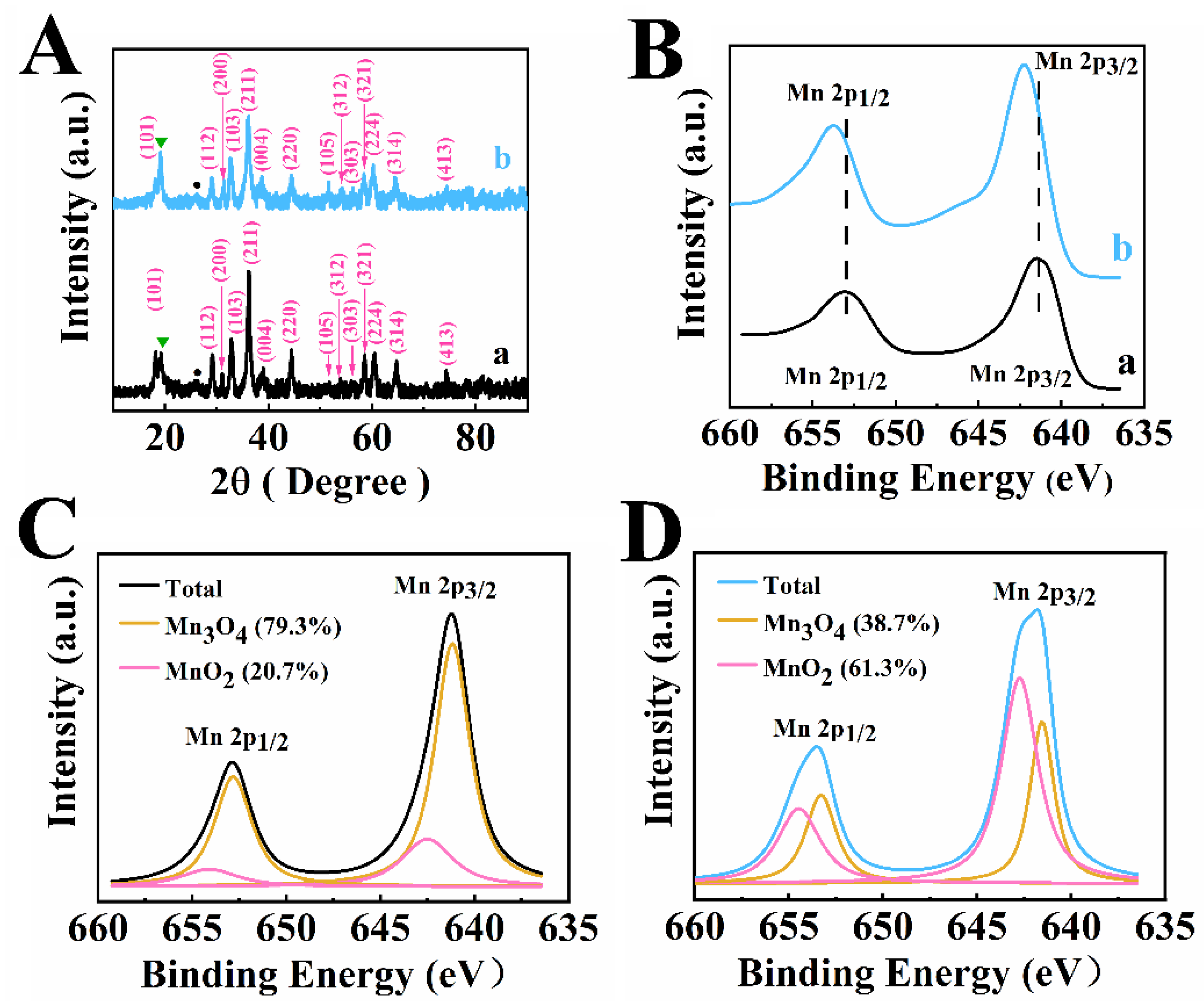
3. Results and Discussion

Figure 1A shows X-ray diffraction patterns of Mn3O4-MWCNT composites prepared by methods 1 and 2. The diffraction patterns show major peaks of Mn3O4, corresponding to the JCPDS file 001-1127 and peaks of MWCNT, corresponding to the JCPDS file 058-1638. The X-ray diffraction pattern of the material prepared by method 1 showed a very small peak of MnO2, corresponding to the JCPDS file 083-6090. The relative intensity of this peak was higher for the material prepared by method 2. In this investigation, Mn2+ salt was used for the synthesis of manganese oxide. However, Mn2+O and Mn2+(OH)2 are unstable and converted to oxides with higher oxidation state in air [20,21,22,48].
The XPS data for the materials prepared by methods 1 and 2 is presented in Figure 1C,D. It should be noted that literature XPS data [49,50,51] for Mn3O4 showed co-existence of Mn2+, Mn3+, and Mn4+. The peaks corresponding to the 2p3/2–2p1/2 doublet shifted to higher energies for electrodes, prepared by method 2, compared to the electrodes, prepared by method 1 (Figure 1B). Such shift indicated larger Mn4+ content [51,52] in the samples prepared by method 2. A similar shift was observed in Mn3O4-MnO2 hetero-nanorods [52]. Deconvoluted XPS spectra confirmed enlarged MnO2 surface content in the samples, prepared by method 2 (Figure 1C,D).
In this investigation RL were used as a capping agent for the synthesis of Mn3O4 in method 2 and a co-dispersing agent for Mn3O4 and MWCNT in methods 1 and 2. RL biosurfactants are amphiphilic glycolipids, produced by Pseudomonas aeruginosa [26]. As received RL was a mixture of mono-RL and di-RL. Figure 2 shows chemical structures of RL. The structures contain rhamnose and fatty acid moieties [26]. The amphiphilic structure of RL and electric charge of their carboxylic groups in solutions are important factors, which make RL promising dispersants for electrostatic dispersion of materials. For the investigation of dispersion properties of RL, Mn3O4 particles were prepared by method 1 without MWCNT, washed, dried, and redispersed in water in the presence of RL with Mn3O4:RL mass ratio 4:1. MWCNT were dispersed in water in the presence of RL with MWCNT:RL mass ratio of 1:1. Sedimentation tests showed colloidal stability of the obtained suspensions for more than one week. It should be noted that metal oxide nanoparticles often form agglomerates due to their high surface energy. The condensation of surface OH groups also promotes agglomeration. The as-received MWCNT used in this investigation consisted of large agglomerates with a typical size of 0.5 mm [53]. The ability to co-disperse Mn3O4 and MWCNT using a RL as a co-dispersant is important for their efficient mixing. It is suggested that RL adsorbed on Mn3O4 and MWCNT and allowed for their electrostatic dispersion. The adsorption of RL on MWCNT resulted from hydrophobic interactions of fatty acid moieties of RL with carbon nanotubes [54]. It is known that RL forms complexes with Mn [55,56]. Therefore, the complexation Mn atoms on the Mn3O4 particle surface with RL can explain the RL adsorption on Mn3O4.
Figure 3 shows TEM images of Mn3O4 prepared by methods 1 and 2 without MWCNT.
The TEM images of Mn3O4 prepared by method 1 without a capping agent contained large agglomerates of particles of irregular shape (Figure 3A,B). The morphology of Mn3O4 particles prepared using RL as a capping agent in method 2 was different (Figure 3C,D). The primary particles were larger and showed crystalline faces. The typical size of the particles was about 50 nm. The particles prepared in the presence of RL as a capping agent showed reduced agglomeration (Figure 3C,D). Therefore, the results of TEM studies showed that the morphology of the synthesized Mn3O4 was influenced by RL.
FTIR studies were performed to analyze the RL adsorption. The FTIR spectrum of as-received RL (Figure 4a) showed absorptions at 2853, 2923 and 2958 cm−1, which can be attributed to the asymmetric and symmetric stretching vibrations of the CH2 and CH3 groups [57] of RL. Such absorptions were not observed in the spectrum of Mn3O4 prepared by method 1 without RL (Figure 4b).
For comparison, the Mn3O4 particles prepared by method 1 were dispersed in the presence of RL. The obtained suspensions were filtered, washed and dried. The FTIR spectrum of obtained powders (Figure 4c) showed absorption peaks, similar to those observed in the spectrum of RL (Figure 4a). Similar absorptions were observed in the spectrum of Mn3O4 prepared by method 2 (Figure 4d). Therefore, the results of FTIR studies showed that RL absorbed on the Mn3O4 particles during or after synthesis.
Figure 5 shows SEM images of composite electrodes, which were fabricated using Mn3O4-MWCNT composites, prepared by methods 1 and 2. The SEM image of electrodes prepared by method 1 showed that the size of primary Mn3O4 particles was below 100 nm. However, the Mn3O4 particles formed agglomerates. This resulted in the areas with larger contents of Mn3O4 or MWCNT and indicated poor mixing of the components. In contrast, such areas were not observed in the SEM images of the electrodes prepared by method 2, which facilitated improved mixing of Mn3O4 or MWCNT. CV studies of the electrodes prepared by method 1 showed nearly rectangular CVs for TP 1 (Figure 6A). However, CV areas increased during cycling. Figure 6B presents CVs for TPs 1–5 at a scan rate of 10 mV s−1. Significant increase in CV areas indicates increase in capacitance during cycling. This agrees with previous investigations [20,21,22], which showed that time consuming activation is required for Mn3O4 electrodes with high active mass. Such a time-consuming activation procedure must be avoided for practical applications. Activation of the electrodes prepared by method 1 required 5 TPs and each TP involved testing a scan rates of 2, 5, 10, 20, 50 and 100 mV s−1. The electrodes prepared by method 2 showed significantly higher currents for TP 1 (Figure 6C), compared to electrodes prepared by method 1 (Figure 6A). The higher currents indicated higher capacitance. The electrodes prepared by method 2 showed reduced variations in CV areas during cycling. Figure 6D presents CVs at a scan rate of 10 mV s−1. Very small variations in CV were observed for TPs 1–3. The CV obtained at TP 3 showed slightly improved rectangular shape, compared to the CV for TP 1.
The areas of CV remained practically without change for TP 4 and TP 5 for electrodes prepared by method 2. CV area for TP 1 for electrode prepared by method 2 (Figure 6(Da)) was larger than the area of CV for TP 5 for the electrode prepared by method 1 (Figure 6(Be)). This indicates higher capacitance of the electrodes prepared by method 2, compared to method 1. Moreover, the need in time consuming activation process can be avoided for electrodes prepared by method 2.
Figure 7A shows capacitances calculated from the CV data for electrodes prepared by method 1 for TPs 1–5. The capacitance of supercapacitor electrodes usually decreases with increasing scan rate [58] due to the diffusion limitations in pores. However, capacitances for TP 1 and TP 2 showed maxima at a scan rate of 20 mV s−1. This can be attributed to electrode activation during initial cycling at low scan rates. Numerous XPS studies showed that the activation process results in oxidation of Mn2+ and Mn3+ ions on the Mn3O4 particle surface during cycling in the positive potential range and linked this process to the capacitance increase [20,21,22,25]. The oxidation process was influenced by the duration of the application of a positive potential. Therefore, it is not surprising that the activation process was enhanced at low scan rates.
Capacitance increased and impedance decreased with increasing number of TP (Figure 7A,B). The highest capacitance at a scan rate of 2 mV s−1 was found to be 4.14 F cm−2 (104.4 F g−1) for TP 5 in the method 1. Testing results indicated that activation process is necessary for achieving high capacitance and reducing impedance of electrodes prepared by method 1. As pointed out above, such time-consuming activation process must be avoided for practical applications.
Electrodes, prepared by method 2, did not show significant variations of capacitance and impedance during cycling. The capacitance obtained for the first cycle of TP 1 at a scan rate of 2 mV s−1 was 5.67 F cm−2 (141.6 F g−1) for electrodes prepared by method 2. It is higher than the capacitance obtained at the same scan rate for TP5 for electrodes prepared by method 1. A capacitance of 6.11 F cm−2 (153 F g−1) was obtained at a scan rate of 2 mV s−1 for TP 3. The real and imaginary parts of impedance for electrode, prepared by method 2 for TP 1 were lower than the corresponding values for TP 5 for electrode, prepared by method 1. This indicated lower resistance and higher capacitance of the electrodes prepared by method 2. The electrodes, prepared by method 2 showed very small variations in capacitance and impedance for TP 4 and TP 5, compared to TP 3.
CV data indicated that significantly higher capacitance was achieved by method 2 and in this method the time-consuming activation procedure can be avoided. This opens an avenue for practical applications of Mn3O4 based electrodes with high active mass loading. It should be noted that small variations in capacitance were observed in method 2. However, variations in capacitance were also observed for other electrodes, such as MnO2 electrodes during initial cycling [59]. Such capacitance increase of the MnO2 electrodes was attributed to other factors, such as microstructure changes during initial cycling [59].
Figure 8 shows frequency dependences of real (CS′) and imaginary (CS″) components of AC capacitance, derived from the impedance data. In contrast to integral capacitance measured by CV method in a potential window of 0.9 V, the components of the differential AC capacitance were measured at voltage amplitude of 5 mV at an open circuit potential.
Figure 8A shows significant increase of low frequency capacitance CS′ with increasing TP number for electrodes prepared by method 1. The highest CS′ of 3.33 F cm−2 was obtained at a frequency of 10 mHz for TP 5. The analysis of frequency dependences of CS″ showed significant reduction of the relaxation frequency, corresponding to the CS″ maximum with increasing TP number (Figure 8B). The electrode prepared by method 2 showed CS′ of 3.48 F cm−2 at a frequency of 10 mHz (Figure 8C) for TP 1, which is higher than CS′ for electrode prepared by method 1 for TP 5. The CS′ increased for TP 2 and showed very small variation for TPs 3–5. The relaxation frequency of the electrodes prepared by method 2 showed very small changes (Figure 8D), especially after TP 2. Therefore, the behavior of the differential capacitance during TPs 1–5 correlated with behavior of the integral capacitance, derived from the CV data.
The results of the GCD testing of electrodes, prepared by methods 1 and 2, after TP 5 are presented in Figure 9. The GCD curves at different currents showed nearly ideal linear dependences (Figure 9A,C). The electrodes prepared by method 1 and method 2 showed capacitances of 5.83 F cm−2 (145.8 F g−1) and 6.07 F cm−2 (151.9 F g−1), respectively, at a current density of 3 mA cm−2 (Figure 9B,D). The capacitances showed slight decrease with increasing current density in the range of 3–10 mA cm−2.
The influence of cycling on capacitive properties of electrodes prepared by methods 1 and 2 was also studied by analyzing CVs at a scan rate of 50 mV s−1. The capacitances for different cycles were normalized by the capacitance obtained at 2000th cycle and presented in Figure 10. The normalized capacitance (CN) for electrodes prepared by method 1 was only 8.3% for the cycle 1.
The electrodes prepared by method 1 showed significant increase of CN during first 500 cycles and further continuous capacitance increase at a reduced rate. The electrodes, prepared by method 2 showed CN of 71% for the cycle 1 and CN of 99% for the cycle 7. The CN showed a maximum of 128% for cycle 151 and then decreased. The rate of the CN decrease reduced after 1000 cycles. The CV data provided additional evidence of significantly faster electrode activation in method 2. However, as pointed out above the activation process is also influenced by the scan rate.
Recent comprehensive review [8] of supercapacitor electrodes with high active mass loadings provided a summary of capacitances for Mn3O4 and MnO2 based electrodes. Table 1 shows capacitances of Mn3O4 electrodes with high active mass loading reported in literature.
It is seen that the areal capacitance achieved in this investigation by method 2 is higher, than that reported in the literature for Mn3O4 based electrodes of high mass. The method used in this investigation is simple and it is based on the use of a natural co-dispersant. Moreover, the capacitance of Mn3O4 based electrodes, prepared by method 2 is comparable with capacitance of advanced MnO2 based electrodes [8]. The time-consuming activation procedure, which limits the applications of Mn3O4 based electrodes, can be practically eliminated in method 2. Therefore, Mn3O4 electrodes represent a promising alternative to the MnO2 based electrodes for the development of asymmetric devices for operation in enlarged voltage window in a neutral electrolyte. It should be noted that the application of capping agents, such as RL for the MnO2 synthesis presents difficulties due to the use of permanganate precursors, which react with organic additives. It can be expected that Mn3O4 electrodes with advanced particle morphologies, prepared using capping agents, can outperform MnO2 electrodes. Moreover, in contrast to MnO2, the spinel type Mn3O4 forms a large variety of spinel solid solutions. Such solutions can enhance capacitance, reduce resistance, and impart other functional properties, such as ferrimagnetic, catalytic and other properties to the Mn3O4 based electrodes.

4. Conclusions

For the first time RL were used as a capping agent for the synthesis of Mn3O4 nanoparticles and as a dispersant for Mn3O4 and MWCNT. The morphology of the synthesized Mn3O4 particles and their dispersion were influenced by RL. The chemical structure of RL facilitated their adsorption on materials of different types, such as Mn3O4 and MWCNT and allowed for their electrostatic dispersion. The ability to co-disperse Mn3O4 and MWCNT facilitated their efficient mixing at the nanometric scale and allowed for the fabrication of advanced cathode materials for asymmetric supercapacitors. The use of RL as a capping agent resulted in higher capacitance of electrodes prepared by method 2, compared to method 1. The highest capacitance of 6.11 F cm−2 (153 F g−1) was obtained from CV data at a scan rate of 2 mV s−1 and 6.07 F cm−2 (151.9 F g−1) at a GCD current density of 3 mA cm−2 in a potential window of 0.9 V in a neutral Na2SO4 electrolyte. The problem of time-consuming activation of Mn3O4 based electrodes can be avoided in the method 2. This makes Mn3O4 a promising material for practical applications in supercapacitors. Of particular importance for future research is the ability to form spinel solid solutions, based on Mn3O4. The development of such solid solutions can result in the development of materials with higher capacitance, reduced resistance and multifunctional materials, combining capacitive, ferrimagnetic, catalytic, and other functional properties.

Supplementary Materials

The following is available online at https://www.mdpi.com/article/10.3390/nano12050803/s1. Figure S1: (A) CVs at scan rates of (a) 2, (b) 10, (c) 20, and (d) 50 mV s−1 for TP 1 and (B) CVs at a scan rate of 10 mV s−1 for (a) TP 1, (b) TP 2, and (c) TP 3 for electrode prepared by method 2; Figure S2: (A) capacitance versus scan rate and (B) impedance data presented in a Nyquist plot for (a) TP 1, (b) TP 2, and (c) TP 3 for electrode prepared by method 2; Figure S3: (A) real and (B) imaginary components of complex capacitance for (a) TP 1, (b) TP 2, (c) TP 3 for electrode prepared by method 2; Figure S4: GCD data for electrodes prepared by method 2, (A) charge-discharge at current densities of (a) 3, (b) 5, (c) 7 and (d) 10 mA cm−2, (B) capacitance versus current density dependence.

Author Contributions

Conceptualization, W.Y. and I.Z.; methodology, W.Y. and I.Z.; software, W.Y.; validation, W.Y. and I.Z.; formal analysis, W.Y. and I.Z.; investigation, W.Y.; resources, I.Z.; data curation, W.Y. and I.Z.; writing—original draft preparation, W.Y. and I.Z.; writing—review and editing, W.Y. and I.Z.; visualization, W.Y.; supervision, I.Z.; project administration, I.Z.; funding acquisition, I.Z. All authors have read and agreed to the published version of the manuscript.

Funding

This research was funded by the Natural Sciences and Engineering Research Council of Canada, grant number RGPIN-2018-04014 and CRC program. Wenjuan Yang received a scholarship from the China Scholarship Council.

Data Availability Statement

The data presented in this study are available in: “Colloidal Processing of Mn3O4-Carbon Nanotube Nanocomposite Electrodes for Supercapacitors” and it’s Supplementary information.

Acknowledgments

SEM investigations were performed at the Canadian Centre for Electron Microscopy.

Conflicts of Interest

The authors declare no conflict of interest.

References

  1. Jansen, F.; Hoffmann, A.; Henkel, J.; Rahimi, K.; Caumanns, T.; Kuehne, A.J.C. Low-Temperature Synthesis of Titanium Oxynitride Nanoparticles. Nanomaterials 2021, 11, 847. [Google Scholar] [CrossRef] [PubMed]
  2. Mourdikoudis, S.; Antonaropoulos, G.; Antonatos, N.; Rosado, M.; Storozhuk, L.; Takahashi, M.; Maenosono, S.; Luxa, J.; Sofer, Z.; Ballesteros, B.; et al. Heat-Up Colloidal Synthesis of Shape-Controlled Cu-Se-S Nanostructures—Role of Precursor and Surfactant Reactivity and Performance in N2 Electroreduction. Nanomaterials 2021, 11, 3369. [Google Scholar] [CrossRef] [PubMed]
  3. Zhitomirsky, I.; Gal-Or, L. Formation of hollow fibers by electrophoretic deposition. Mater. Lett. 1999, 38, 10–17. [Google Scholar] [CrossRef]
  4. Pranyoto, N.; Dewi Susanti, Y.; Joseph Ondang, I.; Angkawijaya, A.E.; Edi Soetaredjo, F.; Santoso, S.P.; Yuliana, M.; Ismadji, S.; Budi Hartono, S. Facile Synthesis of Silane-Modified Mixed Metal Oxide as Catalyst in Transesterification Processes. Nanomaterials 2022, 12, 245. [Google Scholar] [CrossRef] [PubMed]
  5. Wang, Q.; Yan, Q.; Zhao, Y.; Ren, J.; Ai, N. Preparation of Amine-Modified Cu-Mg-Al LDH Composite Photocatalyst. Nanomaterials 2022, 12, 127. [Google Scholar] [CrossRef]
  6. Parveen, S.; Vilela, B.; Lagido, O.; Rana, S.; Fangueiro, R. Development of Multi-Scale Carbon Nanofiber and Nanotube-Based Cementitious Composites for Reliable Sensing of Tensile Stresses. Nanomaterials 2022, 12, 74. [Google Scholar] [CrossRef]
  7. Wu, K.; Wang, Y.; Zhitomirsky, I. Electrophoretic deposition of TiO2 and composite TiO2–MnO2 films using benzoic acid and phenolic molecules as charging additives. J. Colloid Interface Sci. 2010, 352, 371–378. [Google Scholar] [CrossRef] [PubMed]
  8. Chen, R.; Yu, M.; Sahu, R.P.; Puri, I.K.; Zhitomirsky, I. The Development of Pseudocapacitor Electrodes and Devices with High Active Mass Loading. Adv. Energy Mater. 2020, 10, 1903848. [Google Scholar] [CrossRef]
  9. Hussain, S.; Yang, X.; Aslam, M.K.; Shaheen, A.; Javed, M.S.; Aslam, N.; Aslam, B.; Liu, G.; Qiao, G. Robust TiN nanoparticles polysulfide anchor for Li–S storage and diffusion pathways using first principle calculations. Chem. Eng. J. 2020, 391, 123595. [Google Scholar] [CrossRef]
  10. Salunkhe, R.R.; Kaneti, Y.V.; Yamauchi, Y. Metal–organic framework-derived nanoporous metal oxides toward supercapacitor applications: Progress and prospects. ACS Nano 2017, 11, 5293–5308. [Google Scholar] [CrossRef]
  11. He, T.; Fu, Y.; Meng, X.; Yu, X.; Wang, X. A novel strategy for the high performance supercapacitor based on polyacrylonitrile-derived porous nanofibers as electrode and separator in ionic liquid electrolyte. Electrochim. Acta 2018, 282, 97–104. [Google Scholar] [CrossRef]
  12. Wang, J.; Huang, Y.; Han, X.; Li, Z.; Zhang, S.; Zong, M. A flexible Zinc-ion hybrid supercapacitor constructed by porous carbon with controllable structure. Appl. Surf. Sci. 2022, 579, 152247. [Google Scholar] [CrossRef]
  13. Wang, D.-W.; Li, F.; Cheng, H.-M. Hierarchical porous nickel oxide and carbon as electrode materials for asymmetric supercapacitor. J. Power Sources 2008, 185, 1563–1568. [Google Scholar] [CrossRef]
  14. You, B.; Jiang, J.; Fan, S. Three-dimensional hierarchically porous all-carbon foams for supercapacitor. ACS Appl. Mater. Interfaces 2014, 6, 15302–15308. [Google Scholar] [CrossRef]
  15. Xiong, C.; Li, B.; Lin, X.; Liu, H.; Xu, Y.; Mao, J.; Duan, C.; Li, T.; Ni, Y. The recent progress on three-dimensional porous graphene-based hybrid structure for supercapacitor. Compos. Part B Eng. 2019, 165, 10–46. [Google Scholar] [CrossRef]
  16. Liu, C.; Hou, Y.; Li, Y.; Xiao, H. Heteroatom-doped porous carbon microspheres derived from ionic liquid-lignin solution for high performance Supercapacitors. J. Colloid Interface Sci. 2022, 614, 566–573. [Google Scholar] [CrossRef]
  17. Zhang, H.; Bai, Y.; Chen, H.; Wu, J.; Li, C.M.; Su, X.; Zhang, L. Oxygen-defect-rich 3D porous cobalt-gallium layered double hydroxide for high-performance supercapacitor application. J. Colloid Interface Sci. 2022, 608, 1837–1845. [Google Scholar] [CrossRef] [PubMed]
  18. Yan, Q.; Cheng, Y.; Wang, R.; Sun, J. Recent advances in 3D porous MXenes: Structures, properties and applications. J. Phys. D Appl. Phys. 2021, 55, 093001. [Google Scholar] [CrossRef]
  19. Wang, T.; He, X.; Gong, W.; Kou, Z.; Yao, Y.; Fulbright, S.; Reardon, K.F.; Fan, M. Three-dimensional, heteroatom-enriched, porous carbon nanofiber flexible paper for free-standing supercapacitor electrode materials derived from microalgae oil. Fuel Process. Technol. 2022, 225, 107055. [Google Scholar] [CrossRef]
  20. Poon, R.; Zhitomirsky, I. High areal capacitance of Mn3O4-carbon nanotube electrodes. Mater. Lett. 2018, 215, 4–7. [Google Scholar] [CrossRef]
  21. Ata, M.S.; Milne, J.; Zhitomirsky, I. Fabrication of Mn3O4–carbon nanotube composites with high areal capacitance using cationic and anionic dispersants. J. Colloid Interface Sci. 2018, 512, 758–766. [Google Scholar] [CrossRef] [PubMed]
  22. Milne, J.; Zhitomirsky, I. Application of octanohydroxamic acid for liquid-liquid extraction of manganese oxides and fabrication of supercapacitor electrodes. J. Colloid Interface Sci. 2018, 515, 50–57. [Google Scholar] [CrossRef] [PubMed]
  23. Rorabeck, K.; Zhitomirsky, I. Salting-out aided dispersive extraction of Mn3O4 nanoparticles and carbon nanotubes for application in supercapacitors. Colloids Surf. A Physicochem. Eng. Asp. 2021, 618, 126451. [Google Scholar] [CrossRef]
  24. Nagarajan, N.; Cheong, M.; Zhitomirsky, I. Electrochemical capacitance of MnOx films. Mater. Chem. Phys. 2007, 103, 47–53. [Google Scholar] [CrossRef]
  25. Poon, R.; Liang, W.; Zhitomirsky, I. Mn3O4 and (ZnFe) OOH Composites for Supercapacitors with High Active Mass. Metall. Mater. Trans. A 2020, 51, 855–862. [Google Scholar] [CrossRef]
  26. Marchant, R.; Banat, I.M. Microbial biosurfactants: Challenges and opportunities for future exploitation. Trends Biotechnol. 2012, 30, 558–565. [Google Scholar] [CrossRef] [PubMed]
  27. Guo, Y.-P.; Hu, Y.-Y. Solubilization of moderately hydrophobic 17α-ethinylestradiol by mono-and di-rhamnolipid solutions. Colloids Surf. A Physicochem. Eng. Asp. 2014, 445, 12–20. [Google Scholar] [CrossRef]
  28. Costa, S.G.; Nitschke, M.; Lépine, F.; Déziel, E.; Contiero, J. Structure, properties and applications of rhamnolipids produced by Pseudomonas aeruginosa L2-1 from cassava wastewater. Process Biochem. 2010, 45, 1511–1516. [Google Scholar] [CrossRef]
  29. Nitschke, M.; Costa, S.G.; Contiero, J. Structure and applications of a rhamnolipid surfactant produced in soybean oil waste. Appl. Biochem. Biotechnol. 2010, 160, 2066–2074. [Google Scholar] [CrossRef] [PubMed]
  30. Perfumo, A.; Rudden, M.; Smyth, T.J.; Marchant, R.; Stevenson, P.S.; Parry, N.J.; Banat, I.M. Rhamnolipids are conserved biosurfactants molecules: Implications for their biotechnological potential. Appl. Microbiol. Biotechnol. 2013, 97, 7297–7306. [Google Scholar] [CrossRef] [PubMed]
  31. Lang, S.; Wullbrandt, D. Rhamnose lipids–biosynthesis, microbial production and application potential. Appl. Microbiol. Biotechnol. 1999, 51, 22–32. [Google Scholar] [CrossRef] [PubMed]
  32. Liu, H.; Shao, B.; Long, X.; Yao, Y.; Meng, Q. Foliar penetration enhanced by biosurfactant rhamnolipid. Colloids Surf. B. 2016, 145, 548–554. [Google Scholar] [CrossRef]
  33. Chen, J.; Wu, Q.; Hua, Y.; Chen, J.; Zhang, H.; Wang, H. Potential applications of biosurfactant rhamnolipids in agriculture and biomedicine. Appl. Microbiol. Biotechnol. 2017, 101, 8309–8319. [Google Scholar] [CrossRef]
  34. Vatsa, P.; Sanchez, L.; Clement, C.; Baillieul, F.; Dorey, S. Rhamnolipid biosurfactants as new players in animal and plant defense against microbes. Int. J. Mol. Sci. 2010, 11, 5095–5108. [Google Scholar] [CrossRef] [Green Version]
  35. Tripathy, S.S.; Raichur, A.M. Dispersibility of barium titanate suspension in the presence of polyelectrolytes: A review. J. Dispers. Sci. Technol. 2008, 29, 230–239. [Google Scholar] [CrossRef]
  36. Raichur, A.M. Dispersion of colloidal alumina using a rhamnolipid biosurfactant. J. Dispers. Sci. Technol. 2007, 28, 1272–1277. [Google Scholar] [CrossRef]
  37. Quevedo, I.R.; Olsson, A.L.; Tufenkji, N. Deposition kinetics of quantum dots and polystyrene latex nanoparticles onto alumina: Role of water chemistry and particle coating. Environ. Sci. Technol. 2013, 47, 2212–2220. [Google Scholar] [CrossRef] [PubMed]
  38. Biswas, M.; Raichur, A.M. Electrokinetic and rheological properties of nano zirconia in the presence of rhamnolipid biosurfactant. J. Am. Ceram. Soc. 2008, 91, 3197–3201. [Google Scholar] [CrossRef]
  39. Szymanska, A.; Sadowski, Z. Effects of biosurfactants on surface properties of hematite. Adsorption 2010, 16, 233–239. [Google Scholar] [CrossRef] [Green Version]
  40. Narayanan, J.; Ramji, R.; Sahu, H.; Gautam, P. Synthesis, stabilisation and characterisation of rhamnolipid-capped ZnS nanoparticles in aqueous medium. IET Nanobiotechnol. 2010, 4, 29–34. [Google Scholar] [CrossRef] [PubMed]
  41. Palanisamy, P.; Raichur, A.M. Synthesis of spherical NiO nanoparticles through a novel biosurfactant mediated emulsion technique. Mater. Sci. Eng. C 2009, 29, 199–204. [Google Scholar] [CrossRef]
  42. Salazar-Bryam, A.M.; Yoshimura, I.; Santos, L.P.; Moura, C.C.; Santos, C.C.; Silva, V.L.; Lovaglio, R.B.; Marques, R.F.C.; Junior, M.J.; Contiero, J. Silver nanoparticles stabilized by ramnolipids: Effect of pH. Colloids Surf. B. 2021, 205, 111883. [Google Scholar] [CrossRef] [PubMed]
  43. Zhu, J.; Wu, Q.; Li, J. Review And Prospect of Mn3O4-Based Composite Materials For Supercapacitor Electrodes. ChemistrySelect 2020, 5, 10407–10423. [Google Scholar] [CrossRef]
  44. Van der Biest, O.O.; Vandeperre, L.J. Electrophoretic deposition of materials. Annu. Rev. Mater. Sci. 1999, 29, 327–352. [Google Scholar] [CrossRef]
  45. Su, Y.; Zhitomirsky, I. Electrophoretic deposition of graphene, carbon nanotubes and composite films using methyl violet dye as a dispersing agent. Colloids Surf. A Physicochem. Eng. Asp. 2013, 436, 97–103. [Google Scholar] [CrossRef]
  46. Zhitomirsky, I.; Petric, A. Electrophoretic deposition of electrolyte materials for solid oxide fuel cells. J. Mater. Sci. 2004, 39, 825–831. [Google Scholar] [CrossRef]
  47. Zhitomirsky, I.; Petric, A. Electrophoretic deposition of ceramic materials for fuel cell applications. J. Eur. Ceram. Soc. 2000, 20, 2055–2061. [Google Scholar] [CrossRef]
  48. Moon, J.; Awano, M.; Takagi, H.; Fujishiro, Y. Synthesis of nanocrystalline manganese oxide powders: Influence of hydrogen peroxide on particle characteristics. J. Mater. Res. 1999, 14, 4594–4601. [Google Scholar] [CrossRef]
  49. Sambandam, B.; Soundharrajan, V.; Song, J.; Kim, S.; Jo, J.; Tung, D.P.; Kim, S.; Mathew, V.; Kim, J. A sponge network-shaped Mn3O4/C anode derived from a simple, one-pot metal organic framework-combustion technique for improved lithium ion storage. Inorg. Chem. Front. 2016, 3, 1609–1615. [Google Scholar] [CrossRef]
  50. Raj, A.M.E.; Victoria, S.G.; Jothy, V.B.; Ravidhas, C.; Wollschläger, J.; Suendorf, M.; Neumann, M.; Jayachandran, M.; Sanjeeviraja, C. XRD and XPS characterization of mixed valence Mn3O4 hausmannite thin films prepared by chemical spray pyrolysis technique. Appl. Surf. Sci. 2010, 256, 2920–2926. [Google Scholar]
  51. Tholkappiyan, R.; Naveen, A.N.; Vishista, K.; Hamed, F. Investigation on the electrochemical performance of hausmannite Mn3O4 nanoparticles by ultrasonic irradiation assisted co-precipitation method for supercapacitor electrodes. J. Taibah Univ. Sci. 2018, 12, 669–677. [Google Scholar] [CrossRef] [Green Version]
  52. Zeng, F.; Pan, Y.; Yang, Y.; Li, Q.; Li, G.; Hou, Z.; Gu, G. Facile construction of Mn3O4-MnO2 hetero-nanorods/graphene nanocomposite for highly sensitive electrochemical detection of hydrogen peroxide. Electrochim. Acta 2016, 196, 587–596. [Google Scholar] [CrossRef]
  53. Wallar, C.; Poon, R.; Zhitomirsky, I. High Areal Capacitance of V2O3–Carbon Nanotube Electrodes. J. Electrochem. Soc. 2017, 164, A3620–A3627. [Google Scholar] [CrossRef]
  54. Vadi, M.; Ghaseminejhad, E. Comparative study of isotherms adsorption of Oleic acid by activated carbon and multi-wall carbon nanotube. Orient. J. Chem. 2011, 27, 973. [Google Scholar]
  55. Stacey, S.P.; McLaughlin, M.J.; Çakmak, I.; Hettiarachchi, G.M.; Scheckel, K.G.; Karkkainen, M. Root uptake of lipophilic zinc rhamnolipid complexes. J. Agric. Food Chem. 2008, 56, 2112–2117. [Google Scholar] [CrossRef]
  56. Hogan, D.E.; Curry, J.E.; Pemberton, J.E.; Maier, R.M. Rhamnolipid biosurfactant complexation of rare earth elements. J. Hazard. Mater. 2017, 340, 171–178. [Google Scholar] [CrossRef] [Green Version]
  57. Milne, J.; Silva, R.M.; Zhitomirsky, I. Surface modification and dispersion of ceramic particles using liquid-liquid extraction method for application in supercapacitor electrodes. J. Eur. Ceram. Soc. 2019, 39, 3450–3455. [Google Scholar] [CrossRef]
  58. Shi, K.; Zhitomirsky, I. Fabrication of Polypyrrole-Coated Carbon Nanotubes Using Oxidant–Surfactant Nanocrystals for Supercapacitor Electrodes with High Mass Loading and Enhanced Performance. ACS Appl. Mater. Interfaces 2013, 5, 13161–13170. [Google Scholar] [CrossRef]
  59. Rorabeck, K.; Zhitomirsky, I. Dispersant Molecules with Functional Catechol Groups for Supercapacitor Fabrication. Molecules 2021, 26, 1709. [Google Scholar] [CrossRef]
  60. Poon, R.; Zhao, X.; Ata, M.S.; Clifford, A.; Zhitomirsky, I. Phase transfer of oxide particles for application in thin films and supercapacitors. Ceram. Int. 2017, 43, 8314–8320. [Google Scholar] [CrossRef]
  61. Poon, R.; Zhitomirsky, I. Application of Cyrene as a solvent and dispersing agent for fabrication of Mn3O4-carbon nanotube supercapacitor electrodes. Colloid Interface Sci. Commun. 2020, 34, 100226. [Google Scholar] [CrossRef]
  62. Rorabeck, K.; Zhitomirsky, I. Application of Octanohydroxamic Acid for Salting out Liquid–Liquid Extraction of Materials for Energy Storage in Supercapacitors. Molecules 2021, 26, 296. [Google Scholar] [CrossRef] [PubMed]
Figure 1. (A) X-ray diffraction patterns for Mn3O4-MWCNT materials prepared by (a) method 1 and (b) method 2, Miller indexes are presented for Mn3O4 phase, JCPDS file 001-1127, ●—(002) peak of MWCNT, JCPDS file 058-1638,▼—(111) peak of MnO2, JCPDS file 083-6090, (BD) XPS data for Mn3O4-MWCNT materials prepared by (B(a) and C) method 1 and (B(b) and D) method 2.
Nanomaterials 12 00803 g001
Figure 2. Chemical structure of RL. Dashed line shows rhamnose moieties.
Nanomaterials 12 00803 g002
Figure 3. TEM images at different magnifications of Mn3O4 prepared by method 1 (A,B) and method 2 (C,D).
Nanomaterials 12 00803 g003
Figure 4. FTIR spectra of (a) as received RL, (b) Mn3O4 prepared without RL by method 1, (c) Mn3O4 prepared without RL by method 1 and dispersed using RL, (d) Mn3O4 prepared using RL as a capping agent by method 2.
Nanomaterials 12 00803 g004
Figure 5. SEM images of electrodes prepared using Mn3O4-MWCNT composites prepared by (A) method 1 and (B) method 2. Arrows show areas with enlarged MWCNT content.
Nanomaterials 12 00803 g005
Figure 6. (A) CVs at scan rates of (a) 2, (b) 10, (c) 20 and (d) 50 mV s−1 for TP1 and (B) CVs at a scan rate of 10 mV s−1 for (a) TP1, (b) TP2, (c) TP3, (d) TP4 and (e) TP5 for electrode prepared by method 1; (C) CVs at scan rates of (a) 2, (b) 10, (c) 20 and (d) 50 mV s−1 for TP1 and (D) CVs at a scan rate of 10 mV s−1 for (a) TP1, (b) TP2, and (c) TP3 for electrode prepared by method 2. Each TP involved testing at scan rates of 2, 5, 10, 20, 50, and 100 mV s−1. The CVs for scan rate of 10 mV s−1 for each TP were selected and presented in (B,D).
Nanomaterials 12 00803 g006
Figure 7. (A) Capacitance versus scan rate and (B) impedance data presented in a Nyquist plot for (a) TP 1, (b) TP 2, (c) TP 3, (d) TP 4 and (e) TP 5 for electrode prepared by method 1, (C) capacitance versus scan rate and (D) impedance data presented in a Nyquist plot for (a) TP 1, (b) TP 2, and (c) TP 3 for electrode prepared by method 2.
Nanomaterials 12 00803 g007
Figure 8. (A) real and (B) imaginary components of complex capacitance for (a) TP 1, (b) TP 2, (c) TP 3, (d) TP 4 and (e) TP 5 for electrode prepared by method 1, (C) real and (D) imaginary components of complex capacitance for (a) TP 1, (b) TP 2, (c) TP 3 for electrode prepared by method 2.
Nanomaterials 12 00803 g008
Figure 9. GCD data for electrodes prepared by (A,B) method 1 and (C,D) method 2, (A,C) charge-discharge at current densities of (a) 3, (b) 5, (c) 7, and (d) 10 mA cm−2, (B,D) capacitance versus current density dependences.
Nanomaterials 12 00803 g009
Figure 10. Capacitance (CN) normalized by capacitance value for 2000th cycle for electrodes prepared by (A) method 1 and (B) method 2, obtained from CV data at a scan rate of 50 mV s−1.
Nanomaterials 12 00803 g010
Table 1. Literature data on capacitances of Mn3O4 based electrodes, containing conductive additives, and tested in Na2SO4 electrolyte.
Active Mass (mg cm−2)Areal Capacitance (F cm−2)Reference
28.42.8[21]
30.42.63[60]
33.04.2[22]
35.03.5[20]
36.03.1[57]
36.03.79[61]
40.14.3[62]
40.06.11this work
Publisher’s Note: MDPI stays neutral with regard to jurisdictional claims in published maps and institutional affiliations.

