
Enhancement of Bacterial Anti-Adhesion Properties on Robust PDMS Micro-Structure Using a Simple Flame Treatment Method

 , and
, and 
Abstract
1. Introduction
2. Materials and Methods
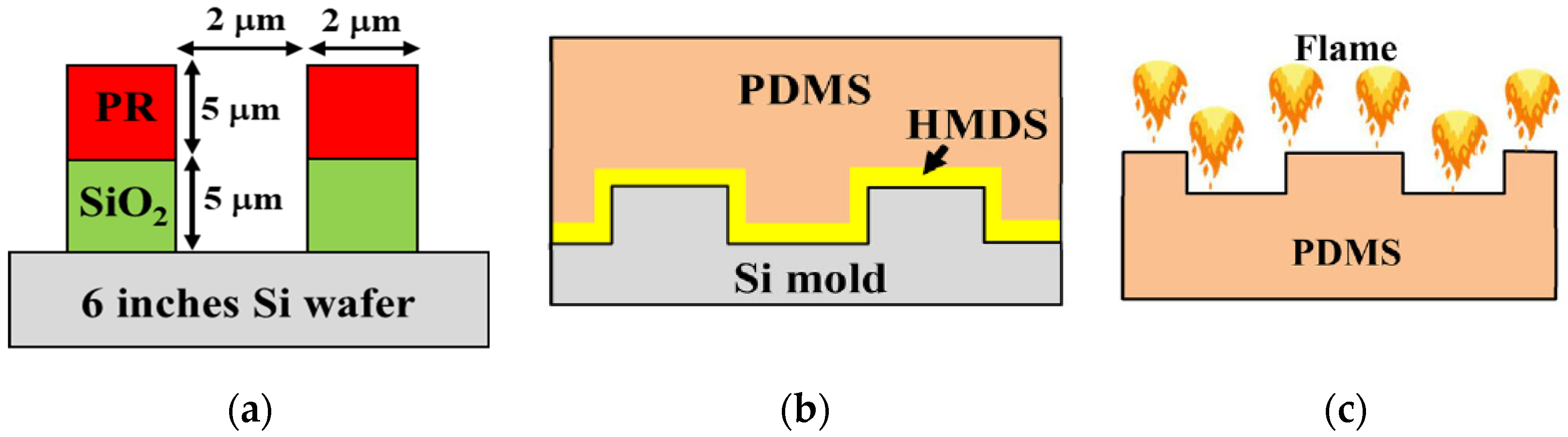
2.1. Silicon Master Mold Fabrication
2.2. Soft Lithography Process for PDMS Replication
2.3. Modification of PDMS Surface by the Flame Treatment Process
2.4. Surface Characterizations
2.5. Bacterial Anti-Adhesion Testing
2.5.1. Bacterial Culture
2.5.2. Crystal Violet Stain
3. Results
3.1. Surface Morphology and Surface Roughness
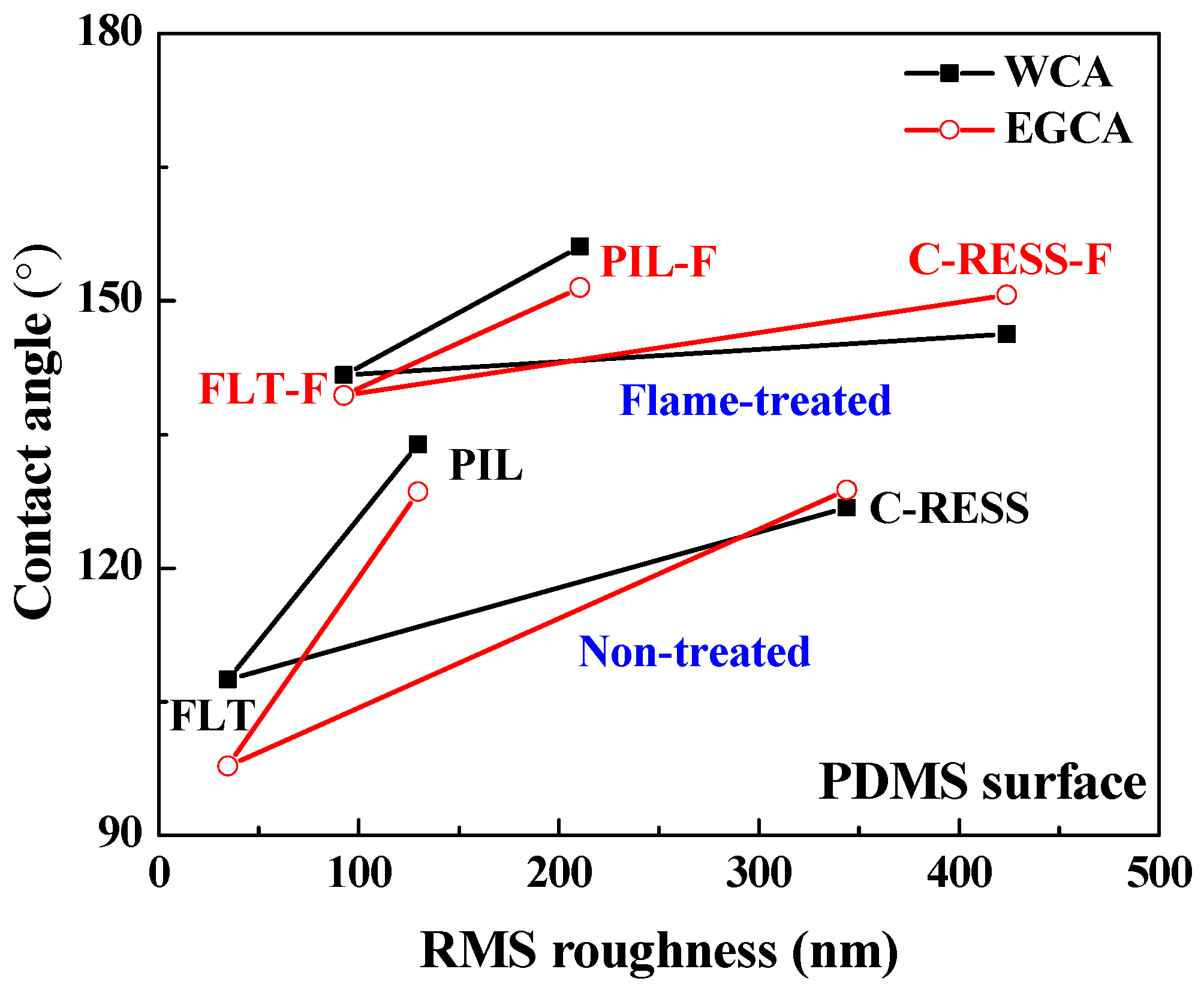
3.2. Water and Ethylene Glycol Contact Angles
3.3. Static Biofilm Formation (Crystal Violet Stain) and Bacterial Anti-Adhesion
4. Discussion
5. Conclusions
Author Contributions
Funding
Data Availability Statement
Acknowledgments
Conflicts of Interest
References
- Bixler, G.D.; Bhushan, B. Biofouling: Lessons from nature. Philos. Trans. R. Soc. London. Ser. A Math. Phys. Eng. Sci. 2012, 370, 2381–2417. [Google Scholar] [CrossRef] [PubMed]
- Lu, N.; Zhang, W.; Weng, Y.; Chen, X.; Cheng, Y.; Zhou, P. Fabrication of PDMS surfaces with micro patterns and the effect of pattern sizes on bacteria adhesion. Food Control 2016, 68, 344–351. [Google Scholar] [CrossRef]
- WHO. Coronavirus Disease 2019 (COVID-19) Situation Report. Available online: https://covid19.who.int/ (accessed on 8 June 2021).
- Callow, J.A.; Callow, M.E. Trends in the development of environmentally friendly fouling-resistant marine coatings. Nat. Commun. 2011, 2, 244. [Google Scholar] [CrossRef] [PubMed]
- Saber, A.T.; Mortensen, A.; Szarek, J.; Jacobsen, N.R.; Levin, M.; Koponen, I.K.; A Jensen, K.; Vogel, U.; Wallin, H. Toxicity of pristine and paint-embedded TiO2 nanomaterials. Hum. Exp. Toxicol. 2018, 38, 11–24. [Google Scholar] [CrossRef]
- Kim, I.-S.; Baek, M.; Choi, S.-J. Comparative cytotoxicity of Al2O3, CeO2, TiO2 and ZnO nanoparticles to human lung cells. J. Nanosci. Nanotechnol. 2010, 10, 3453–3458. [Google Scholar] [CrossRef]
- Zhang, X.; Wang, L.; Levänen, E. Superhydrophobic surfaces for the reduction of bacterial adhesion. RSC Adv. 2013, 3, 12003–12020. [Google Scholar] [CrossRef]
- Jalil, S.A.; Akram, M.; Bhat, J.A.; Hayes, J.J.; Singh, S.; ElKabbash, M.; Guo, C. Creating superhydrophobic and antibacterial surfaces on gold by femtosecond laser pulses. Appl. Surf. Sci. 2019, 506, 144952. [Google Scholar] [CrossRef]
- Berendjchi, A.; Khajavi, R.; Yazdanshenas, M.E. Fabrication of superhydrophobic and antibacterial surface on cotton fabric by doped silica- based sols with nanoparticles of copper. Nanoscale Res. Lett. 2011, 6, 594. [Google Scholar] [CrossRef]
- Wu, X.; Yang, F.; Gan, J.; Kong, Z.; Wu, Y. A Superhydrophobic, antibacterial, and durable surface of Poplar wood. Nanomaterials 2021, 11, 1885. [Google Scholar] [CrossRef]
- Zhan, Y.; Yu, S.; Amirfazli, A.; Siddiqui, A.R.; Li, W. Recent advances in antibacterial superhydrophobic coatings. Adv. Eng. Mater. 2021, 2101053. [Google Scholar] [CrossRef]
- Sahin, F.; Celik, N.; Ceylan, A.; Pekdemir, S.; Ruzi, M.; Serdar Onses, M. Antifouling superhydrophobic surfaces with bactericidal and SERS activity. Chem. Eng. J. 2022, 431 Pt 4, 133445. [Google Scholar] [CrossRef]
- Latthe, S.S.; Gurav, A.B.; Maruti, C.S.; Vhatkar, R.S. Recent progress in preparation of superhydrophobic surfaces: A Review. J. Surf. Eng. Mater. Adv. Technol. 2012, 02, 76–94. [Google Scholar] [CrossRef]
- Gao, N.; Yan, Y. Modeling superhydrophobic contact angles and wetting transition. J. Bionic Eng. 2009, 6, 335–340. [Google Scholar] [CrossRef]
- Gogolides, E.; Ellinas, K.; Tserepi, A. Hierarchical micro and nano structured, hydrophilic, superhydrophobic and superoleo-phobic surfaces incorporated in microfluidics, microarrays and lab on chip microsystems. Microelectron. Eng. 2015, 132, 135–155. [Google Scholar] [CrossRef]
- Avrămescu, R.-E.; Ghica, M.V.; Dinu-Pirvu, C.; Prisada, R.; Popa, L. Superhydrophobic natural and artificial surfaces—A structural approach. Materials 2018, 11, 866. [Google Scholar] [CrossRef] [PubMed]
- Barthlott, W.; Mail, M.; Bhushan, B.; Koch, K. Plant surfaces: Structures and functions for biomimetic innovations. Nano-Micro Lett. 2017, 9, 23. [Google Scholar] [CrossRef]
- Bhushan, B.; Jung, Y.C. Wetting study of patterned surfaces for superhydrophobicity. Ultramicroscopy 2007, 107, 1033–1041. [Google Scholar] [CrossRef]
- Ma, S.; Ye, Q.; Pei, X.; Wang, D.; Zhou, F. Antifouling on gecko’s feet inspired fibrillar surfaces: Evolving from land to marine and from liquid repellency to algae resistance. Adv. Mater. Interfaces 2015, 2, 1500257. [Google Scholar] [CrossRef]
- Lin, X.; Hong, J. Recent advances in robust superwettable membranes for oil–water separation. Adv. Mater. Interfaces 2019, 6, 1900126. [Google Scholar] [CrossRef]
- Teisala, H.; Tuominen, M.; Kuusipalo, J. Adhesion mechanism of water droplets on hierarchically rough superhydrophobic rose petal surface. J. Nanomater. 2011, 2011, 1–6. [Google Scholar] [CrossRef]
- Bayer, I.S. Superhydrophobic coatings from ecofriendly materials and processes: A Review. Adv. Mater. Interfaces 2020, 7, 2000095. [Google Scholar] [CrossRef]
- Wenzel, R.N. Resistance of solid surfaces to wetting by water. Ind. Eng. Chem. 1936, 28, 988–994. [Google Scholar] [CrossRef]
- E, J.; Jin, Y.; Deng, Y.; Zuo, W.; Zhao, X.; Han, D.; Peng, Q.; Zhang, Z. Wetting models and working mechanisms of typical surfaces existing in nature and their application on superhydrophobic surfaces: A Review. Adv. Mater. Interfaces 2017, 5, 1701052–1701091. [Google Scholar] [CrossRef]
- Chen, F.; Song, J.; Lu, Y.; Huang, S.; Liu, X.; Sun, J.; Carmalt, C.J.; Parkin, I.P.; Xu, W. Creating robust superamphiphobic coatings for both hard and soft materials. J. Mater. Chem. A 2015, 3, 20999–21008. [Google Scholar] [CrossRef]
- Sabbah, A.; Youssef, A.; Damman, P. Superhydrophobic surfaces created by elastic instability of PDMS. Appl. Sci. 2016, 6, 152. [Google Scholar] [CrossRef]
- Zhang, H.; Lamb, R.; Lewis, J. Engineering nanoscale roughness on hydrophobic surface—preliminary assessment of fouling behavior. Sci. Technol. Adv. Mater. 2005, 6, 236–239. [Google Scholar] [CrossRef]
- Kim, J.U.; Lee, S. Recent advances in unconventional lithography for challenging 3D hierarchical structures and their applications. J. Nanomater. 2016, 2016, 1–17. [Google Scholar] [CrossRef]
- Bae, W.-G.; Kwak, M.K.; Jeong, H.E.; Pang, C.; Jeong, H.; Suh, K.-Y. Fabrication and analysis of enforced dry adhesives with core–shell micropillars. Soft Matter 2012, 9, 1422–1427. [Google Scholar] [CrossRef]
- Atthi, N.; Sripumkhai, W.; Pattamang, P.; Thongsook, O.; Srihapat, A.; Meananeatra, R.; Supadech, J.; Klunngien, N.; Jeamsaksiri, W. Fabrication of robust PDMS micro-structure with hydrophobic and antifouling properties. Microelectron. Eng. 2020, 224, 111255. [Google Scholar] [CrossRef]
- Tuteja, A.; Choi, W.; McKinley, G.H.; Cohen, R.E.; Rubner, M.F. Design parameters for superhydrophobicity and superoleo-phobicity. MRS Bull. 2008, 33, 752–758. [Google Scholar] [CrossRef]
- Yamaguchi, M. Microfabrication of re-entrant surface with hydrophobicity/oleophobicity for liquid foods. Sci. Rep. 2020, 10, 2250–2257. [Google Scholar] [CrossRef] [PubMed]
- Nosonovsky, M.; Bhushan, B. Why re-entrant surface topography is needed for robust oleophobicity. Phil. Trans. R.Soc. A 2016, 374, 20160185. [Google Scholar] [CrossRef] [PubMed]
- Kwon, B.; Kim, J.H. Importance of molds for nanoimprint lithography: Hard, soft, and hybrid molds. J. Nanosci. 2016, 2016, 1–12. [Google Scholar] [CrossRef]
- Li, G.; He, D.; Lin, Y.; Chen, Z.; Liu, Y.; Peng, X. Fabrication of biomimetic superhydrophobic surfaces by a simple flame treatment method. Polym. Adv. Technol. 2016, 27, 1438–1445. [Google Scholar] [CrossRef]
- Farris, S.; Pozzoli, S.; Biagioni, P.; Duó, L.; Mancinelli, S.; Piergiovanni, L. The fundamentals of flame treatment for the surface activation of polyolefin polymers—A review. Polymer 2010, 51, 3591–3605. [Google Scholar] [CrossRef]
- Farris, S.; Pozzoli, S.; La Vecchia, S.; Biagioni, P.; Bianchi, C.L.; Piergiovanni, L. Mapping physicochemical surface modifications of flame-treated polypropylene. Express Polym. Lett. 2014, 8, 256–266. [Google Scholar] [CrossRef]
- Atthi, N.; Sripumkhai, W.; Pattamang, P.; Thongsook, O.; Meananeatra, R.; Saengdee, P.; Srihapat, A.; Supadech, J.; Janseng, T.; Maneesong, A.; et al. Superhydrophobic and superoleophobic properties enhancement on PDMS micro-structure using simple flame treatment method. Microelectron. Eng. 2020, 230, 111362. [Google Scholar] [CrossRef]
- Schift, H.; Saxer, S.; Park, S.; Padeste, C.; Pieles, U.; Gobrecht, J. Controlled co-evaporation of silanes for nanoimprint stamps. Nanotechnology 2005, 16, S171–S175. [Google Scholar] [CrossRef]
- Lee, J.; Sperandio, V.; Frantz, D.E.; Longgood, J.; Camilli, A.; Phillips, M.A.; Michael, A.J. An alternative polyamine biosynthetic pathway is widespread in bacteria and essential for biofilm formation in Vibrio cholerae. J. Biol. Chem. 2009, 284, 9899–9907. [Google Scholar] [CrossRef]
- Sakamoto, A.; Terui, Y.; Horie, C.; Fukui, T.; Masuzawa, T.; Sugawara, S.; Shigeta, K.; Shigeta, T.; Igarashi, K.; Kashiwagi, K. Antibacterial effects of protruding and recessed shark skin micropatterned surfaces of polyacrylate plate with a shallow groove. FEMS Microbiol. Lett. 2014, 361, 10–16. [Google Scholar] [CrossRef]
- Oleksy-Wawrzyniak, M.; Junka, A.; Brożyna, M.; Paweł, M.; Kwiek, B.; Nowak, M.; Mączyńska, B.; Bartoszewicz, M. The in vitro ability of Klebsiella pneumoniae to form biofilm and the potential of various compounds to eradicate it from urinary catheters. Pathogens 2021, 11, 42. [Google Scholar] [CrossRef] [PubMed]
- Xu, T.; Tao, Z.; Li, H.; Tan, X.; Li, H. Effects of deep reactive ion etching parameters on etching rate and surface morphology in extremely deep silicon etch process with high aspect ratio. Adv. Mech. Eng. 2017, 9. [Google Scholar] [CrossRef]
- Karttunen, J.; Kiihamaki, J.; Franssila, S. Loading effects in deep silicon etching. In Micromachining and Microfabrication Process Technology VI; SPIE: Bellingham, WA, USA, 2000; Volume 4174, pp. 90–98. [Google Scholar] [CrossRef]
- Atthi, N.; Na Ubol, P.; Sripumkhai, W.; Pattamang, P.; Meananeatra, R.; Supadech, J.; Jeamsaksiri, W.; Hruanun, C. Fabrication of PDMS with 3D microstructure for antibacterial antifouling applications. In Proceedings of the 65th JSAP Spring Meeting, Tokyo, Japan, 17–20 March 2018; pp. 6–57. [Google Scholar]
- Magin, C.M.; Cooper, S.P.; Brennan, A.B. Non-toxic antifouling strategies. Mater. Today 2010, 13, 36–44. [Google Scholar] [CrossRef]
- Liu, M.; Wang, S.; Jiang, L. Nature-inspired superwettability systems. Nat. Rev. Mater. 2017, 2, 17036. [Google Scholar] [CrossRef]
- Hwang, G.B.; Page, K.; Patir, A.; Nair, S.P.; Allan, E.; Parkin, I.P. The Anti-biofouling properties of superhydrophobic surfaces are short-lived. ACS Nano 2018, 12, 6050–6058. [Google Scholar] [CrossRef] [PubMed]
- Lee, S.W.; Phillips, K.S.; Gu, H.; Kazemzadeh-Narbat, M.; Ren, D. How microbes read the map: Effects of implant topography on bacterial adhesion and biofilm formation. Biomaterials 2021, 268, 120595. [Google Scholar] [CrossRef]
- Schumacher, J.F.; Carman, M.L.; Estes, T.G.; Feinberg, A.W.; Wilson, L.H.; Callow, M.E.; Callow, J.A.; Finlay, J.A.; Brennan, A.B. Engineered antifouling microtopographies—effect of feature size, geometry, and roughness on settlement of zoospores of the green alga Ulva. Biofouling 2007, 23, 55–62. [Google Scholar] [CrossRef]
- Choi, W.; Lee, C.; Yoo, C.H.; Shin, M.G.; Lee, G.W.; Kim, T.-S.; Jung, H.W.; Lee, J.S.; Lee, J.-H. Structural tailoring of shark-skin-mimetic patterned reverse osmosis membranes for optimizing biofouling resistance. J. Membr. Sci. 2020, 595, 117602. [Google Scholar] [CrossRef]
- Dowling, D.; Miller, I.; Ardhaoui, M.; Gallagher, W. Effect of surface wettability and topography on the adhesion of Osteosarcoma cells on plasma-modified polystyrene. J. Biomater. Appl. 2010, 26, 327–347. [Google Scholar] [CrossRef]
- Wu, S.; Zhang, B.; Liu, Y.; Suo, X.; Li, H. Influence of surface topography on bacterial adhesion: A review (Review). Biointerphases 2018, 13, 060801. [Google Scholar] [CrossRef]
- Zheng, S.; Bawazir, M.; Dhall, A.; Kim, H.-E.; He, L.; Heo, J.; Hwang, G. Implication of surface properties, bacterial mobility, and hydrodynamic conditions on bacterial surface sensing and their initial adhesion. Front. Bioeng. Biotechnol. 2021, 9, 82. [Google Scholar] [CrossRef] [PubMed]
- Riedewald, F. Bacterial adhesion to surfaces: The influence of surface roughness. PDA J. Pharm. Sci. Technol. 2006, 60, 164–171. [Google Scholar]
- Takai, M.; Shirai, T.; Ishihara, K. Surface Functionarization of polydimethylsiloxane by photo-induced polymerization of 2-Methacryloyloxyethyl phosphorylcholine for biodevices. J. Photopolym. Sci. Technol. 2011, 24, 597–602. [Google Scholar] [CrossRef][Green Version]
- Preočanin, T.; Selmani, A.; Lindqvist-Reis, P.; Heberling, F.; Kallay, N.; Lützenkirchen, J. Surface charge at Teflon/aqueous solution of potassium chloride interfaces. Colloids Surf. A: Physicochem. Eng. Asp. 2012, 412, 120–128. [Google Scholar] [CrossRef]
- Gottenbos, B.; Grijpma, D.W.; Van Der Mei, H.C.; Feijen, J.; Busscher, H.J. Antimicrobial effects of positively charged surfaces on adhering Gram-positive and Gram-negative bacteria. J. Antimicrob. Chemother. 2001, 48, 7–13. [Google Scholar] [CrossRef] [PubMed]
- Harris, L.G.; Meredith, D.O.; Eschbach, L.; Richards, R.G. Staphylococcus aureus adhesion to standard micro-rough and electropolished implant materials. J. Mater. Sci. Mater. Med. 2007, 18, 1151–1156. [Google Scholar] [CrossRef]


| Sample Type | Pattern Size and Surface Roughness | Surface Wettability | ||||
|---|---|---|---|---|---|---|
| Pattern Width (µm) | Pattern Height (µm) | A.R. | RMS Roughness (nm) | WCA (°) | EGCA (°) | |
| FLT | NA | NA | NA | 34.6 | 107.5 ± 8.1 | 97.8 ± 7.3 |
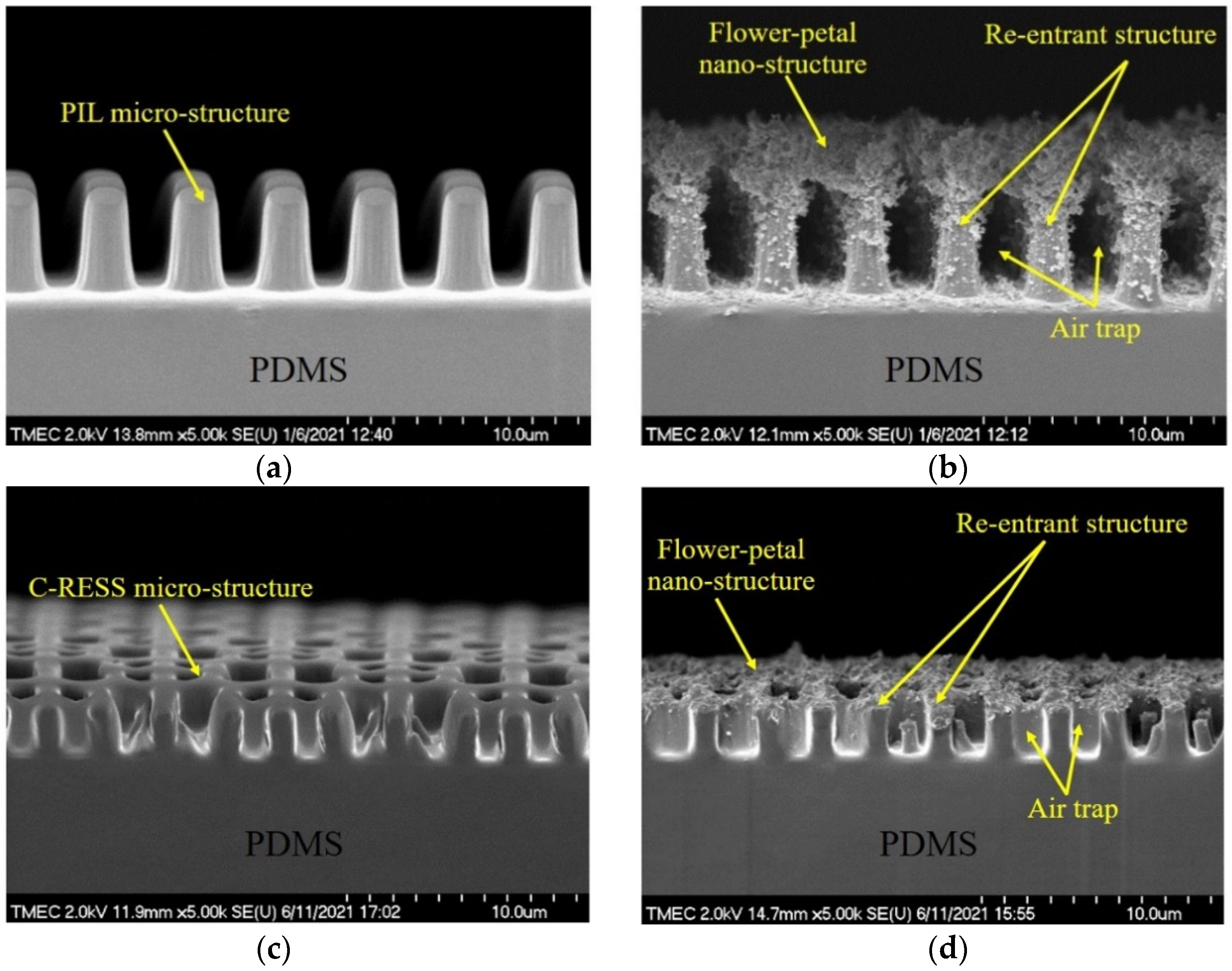
| PIL | 1.87 ± 0.30 | 4.62 ± 0.10 | 2.47 | 92.6 | 141.7 ± 5.5 | 139.4 ± 2.3 |
| C-RESS | 0.50 ± 0.04 | 2.55 ± 0.07 | 5.10 | 344.0 | 126.8 ± 3.2 | 128.8 ± 5.0 |
| Teflon | NA | NA | NA | 77.2 | 102.4 ± 5.1 | 91.5 ± 4.0 |
| FLT-F | NA | NA | NA | 129.6 | 133.9 ± 3.8 | 128.6 ± 5.3 |
| PIL-F | 1.87 ± 0.30 | 7.76 ± 0.13 | 4.14 | 210.5 | 156.1 ± 1.5 | 151.5 ± 2.1 |
| C-RESS-F | 0.50 ± 0.04 | 3.55 ± 0.11 | 7.10 | 424.0 | 146.3 ± 3.5 | 150.7 ± 1.8 |
Publisher’s Note: MDPI stays neutral with regard to jurisdictional claims in published maps and institutional affiliations. |
© 2022 by the authors. Licensee MDPI, Basel, Switzerland. This article is an open access article distributed under the terms and conditions of the Creative Commons Attribution (CC BY) license (https://creativecommons.org/licenses/by/4.0/).
Share and Cite
Houngkamhang, N.; Chaisawat, P.; Joksathit, W.; Samart, S.; Chutipaijit, S.; Radomyos, S.; Saengdee, P.; Atthi, N. Enhancement of Bacterial Anti-Adhesion Properties on Robust PDMS Micro-Structure Using a Simple Flame Treatment Method. Nanomaterials 2022, 12, 557. https://doi.org/10.3390/nano12030557
Houngkamhang N, Chaisawat P, Joksathit W, Samart S, Chutipaijit S, Radomyos S, Saengdee P, Atthi N. Enhancement of Bacterial Anti-Adhesion Properties on Robust PDMS Micro-Structure Using a Simple Flame Treatment Method. Nanomaterials. 2022; 12(3):557. https://doi.org/10.3390/nano12030557
Chicago/Turabian StyleHoungkamhang, Nongluck, Ploymanee Chaisawat, Waisaree Joksathit, Sutichai Samart, Sutee Chutipaijit, Suphichaya Radomyos, Pawasuth Saengdee, and Nithi Atthi. 2022. "Enhancement of Bacterial Anti-Adhesion Properties on Robust PDMS Micro-Structure Using a Simple Flame Treatment Method" Nanomaterials 12, no. 3: 557. https://doi.org/10.3390/nano12030557
APA StyleHoungkamhang, N., Chaisawat, P., Joksathit, W., Samart, S., Chutipaijit, S., Radomyos, S., Saengdee, P., & Atthi, N. (2022). Enhancement of Bacterial Anti-Adhesion Properties on Robust PDMS Micro-Structure Using a Simple Flame Treatment Method. Nanomaterials, 12(3), 557. https://doi.org/10.3390/nano12030557