
Heat Transfer Enhancement in Parabolic through Solar Receiver: A Three-Dimensional Numerical Investigation

 ,
,  , , and
Abstract
:1. Introduction
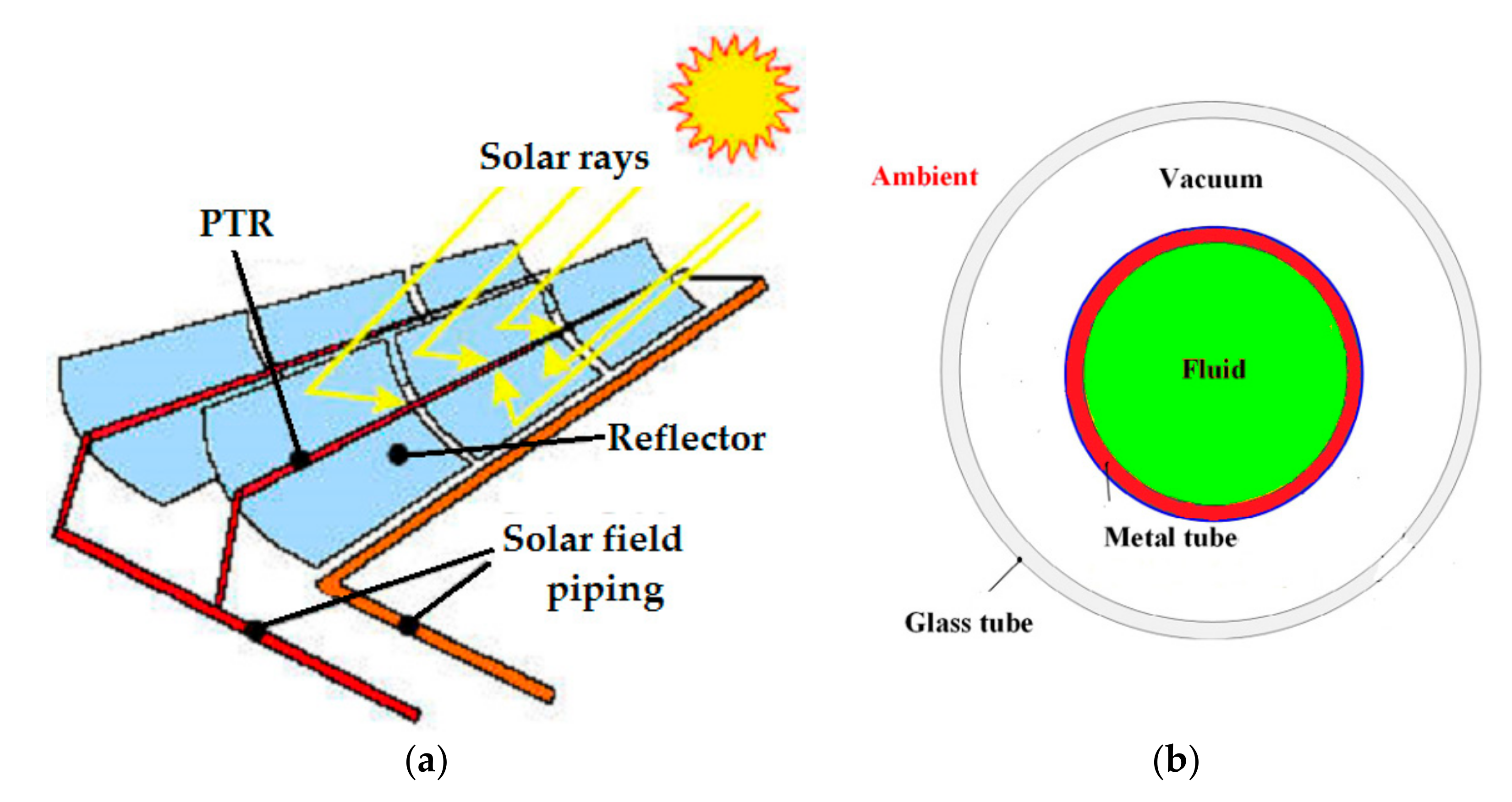
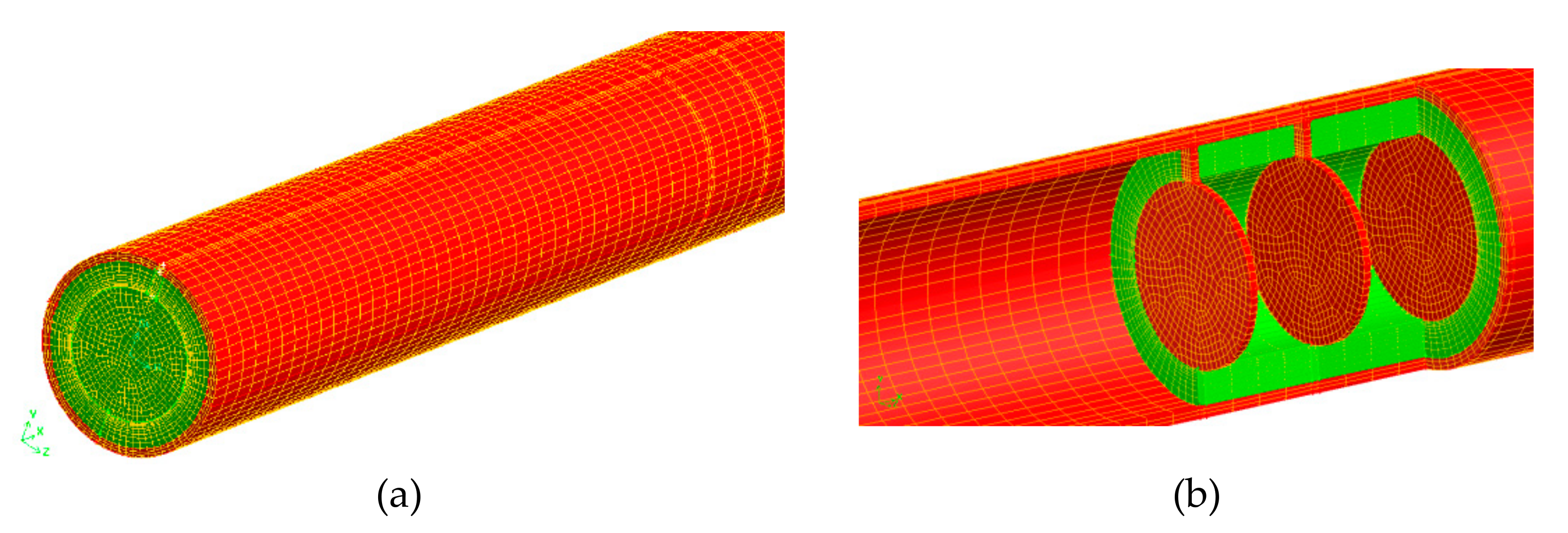
2. Physical Model
2.1. Boundary Conditions
- Fluid inlet;
- Wall boundary condition;
- Fluid outlet: fully developed conditions.
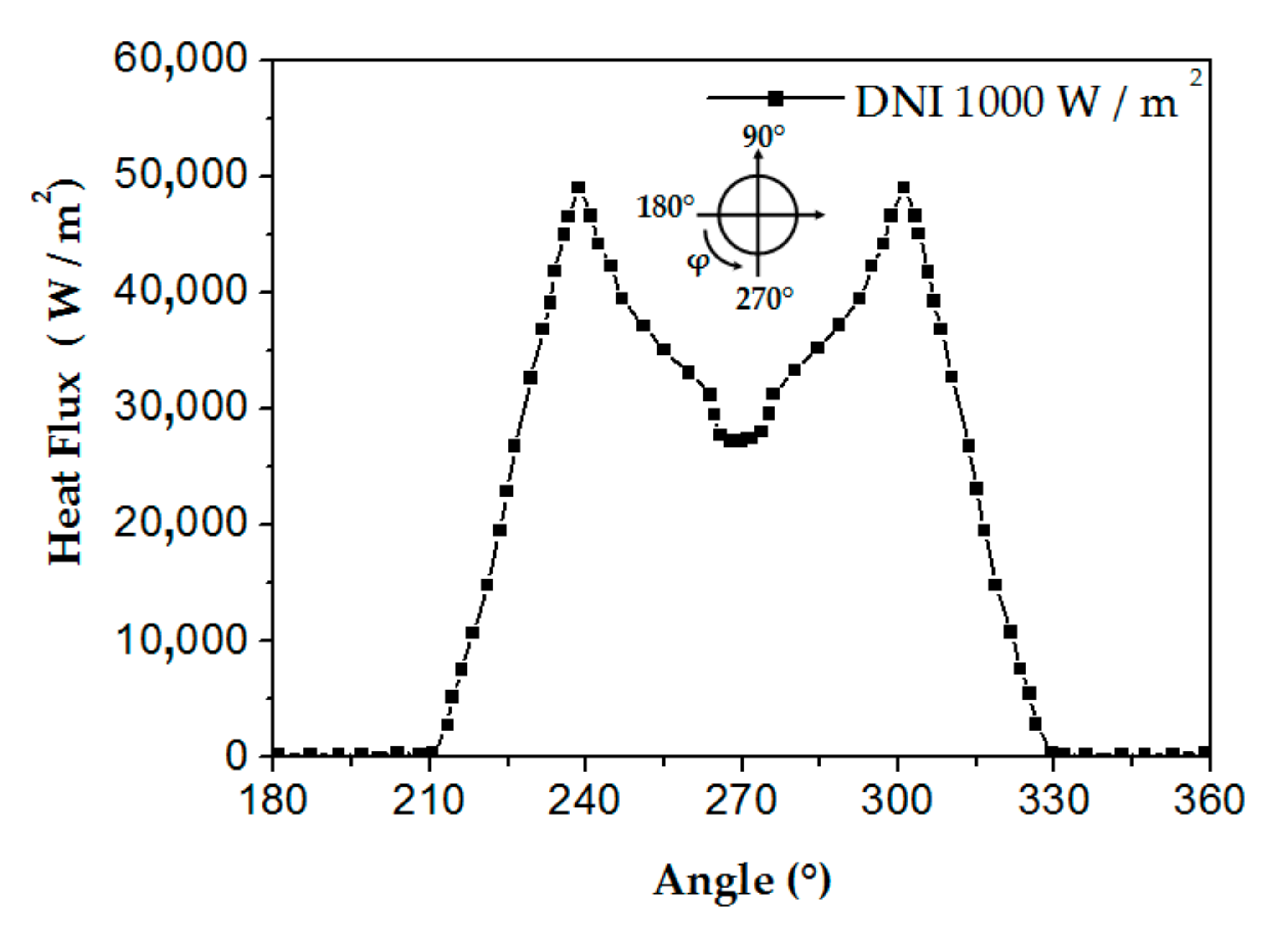
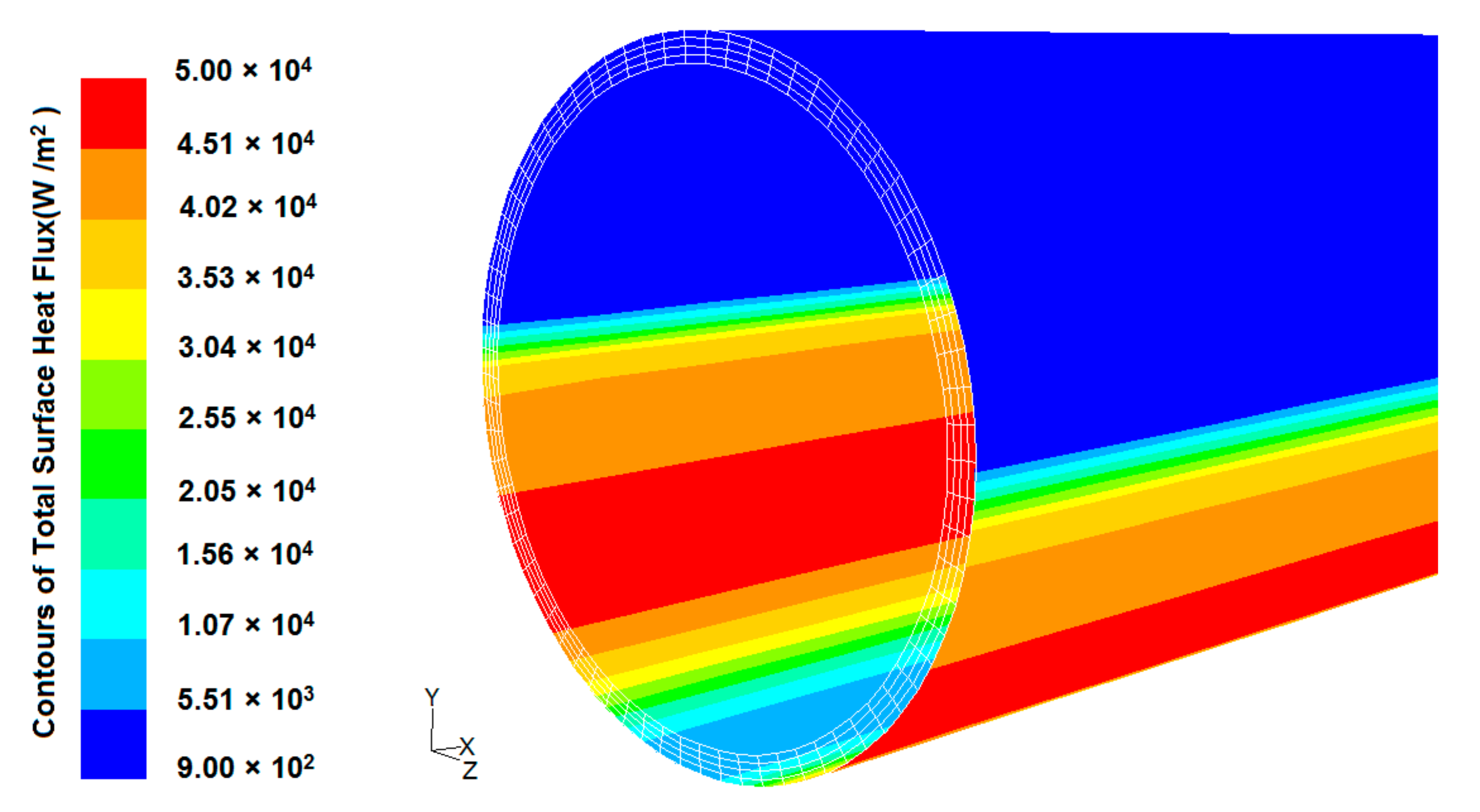
- In this study, the outer absorber’s wall receives a non-uniform heat flux obtained by using MCRT technique, and taking the DNI of 1000 W/m2, the local concentration ratio distribution results are illustrated in Figure 3 and the heat flux distribution on an absorber tube’s surface is shown in Figure 4.
2.2. Thermo-Physical Characteristics of the HTF
2.3. Numerical Method
3. Results and Discussion
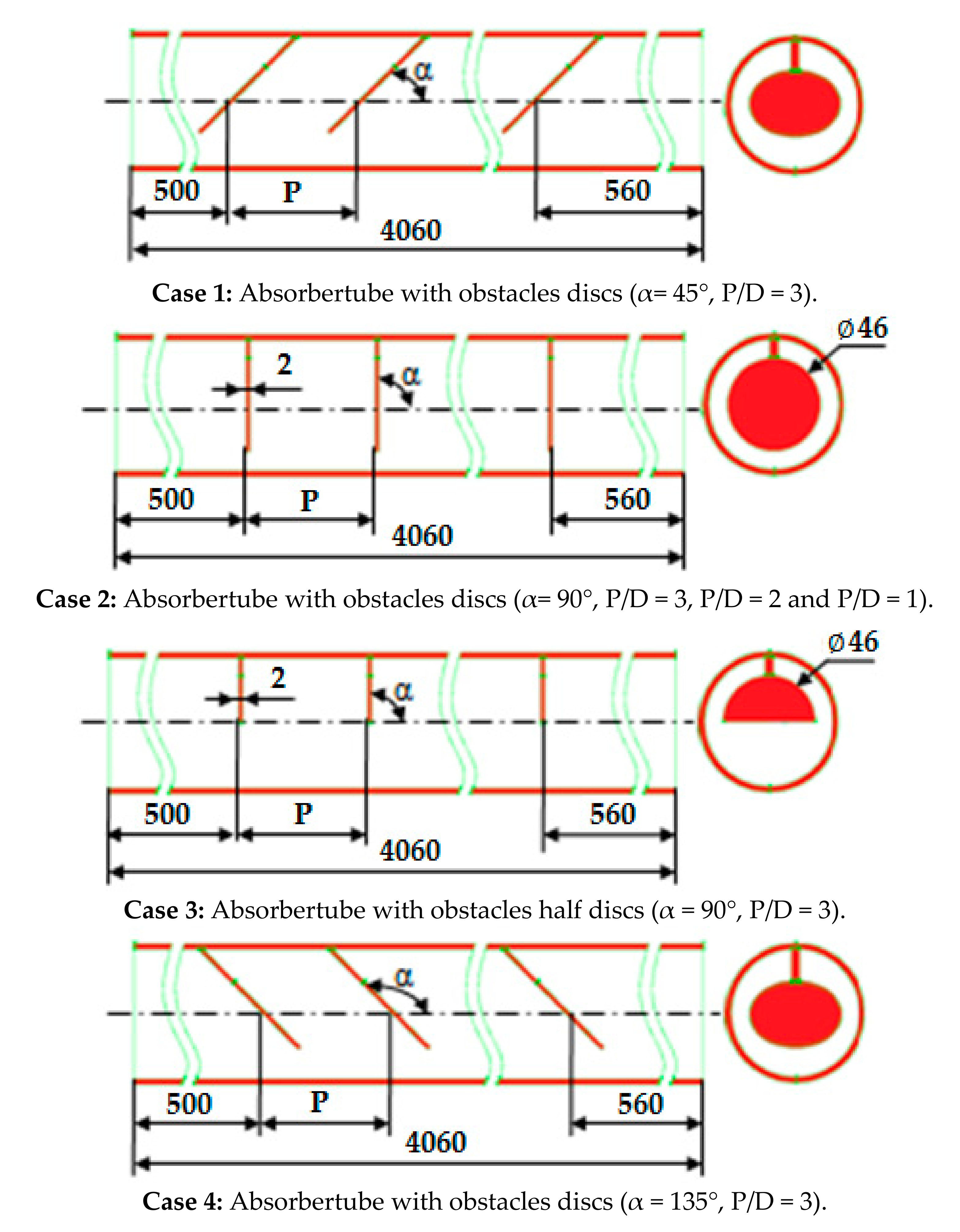
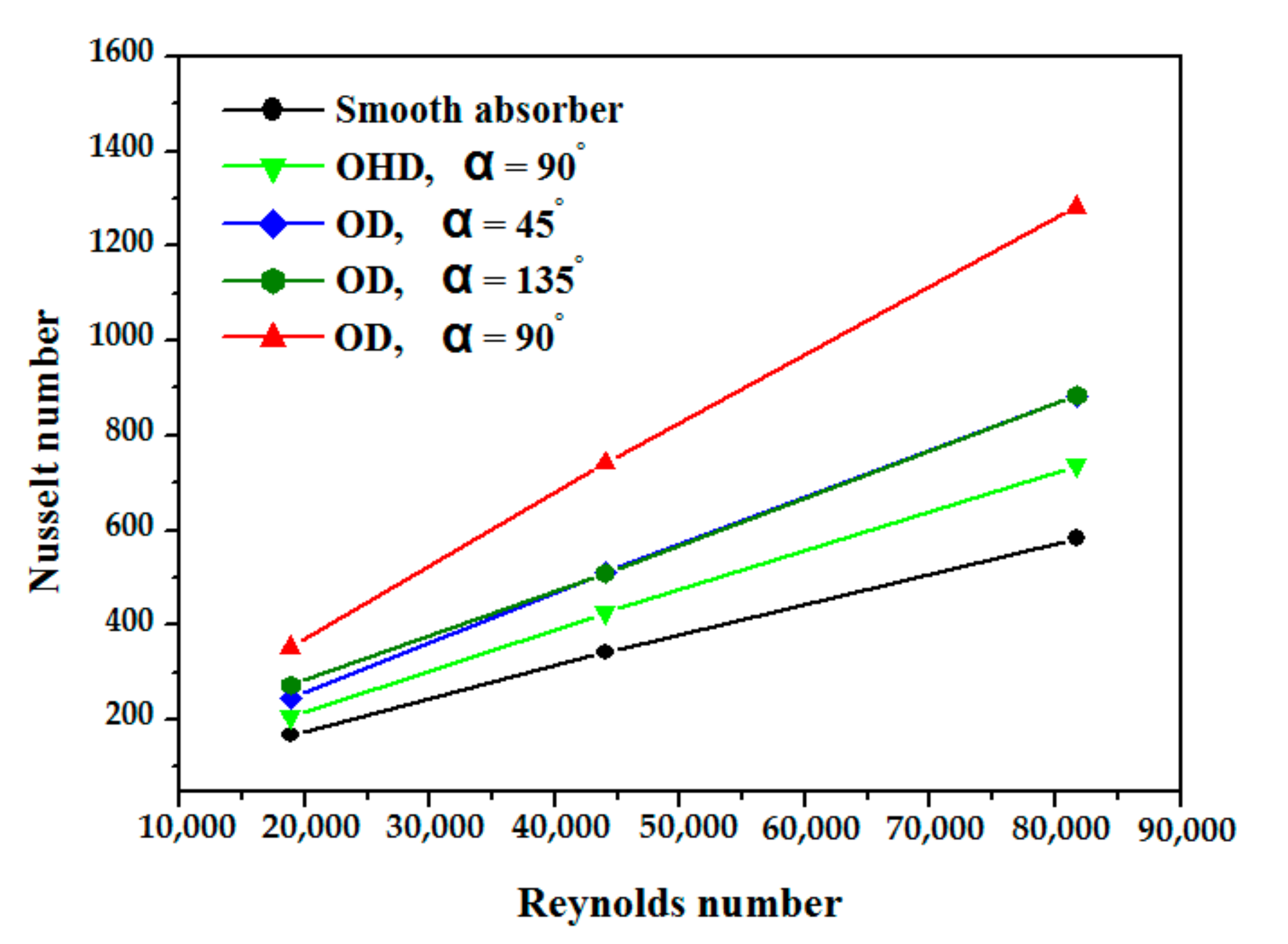
3.1. Obstacle Form and Orientation on Heat Transfer Effect
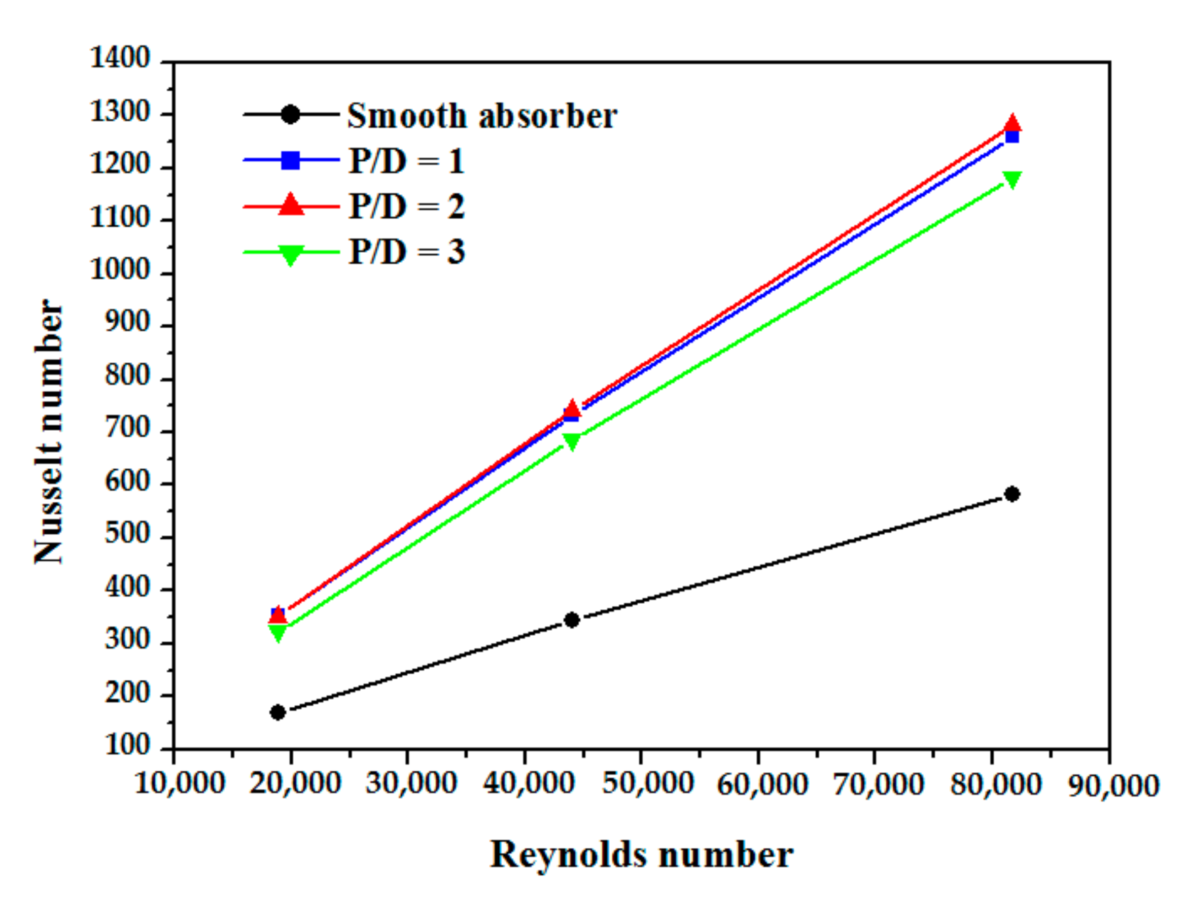
3.2. Effect of Obstacles Spacing on Heat Transfer
3.3. Thermal Performance Analysis
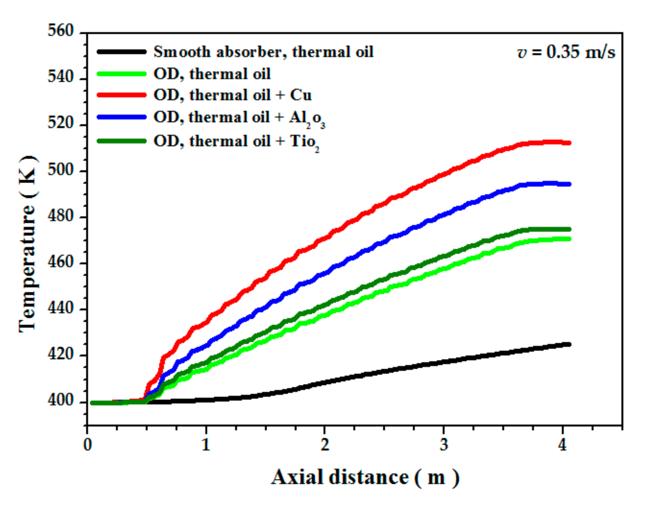
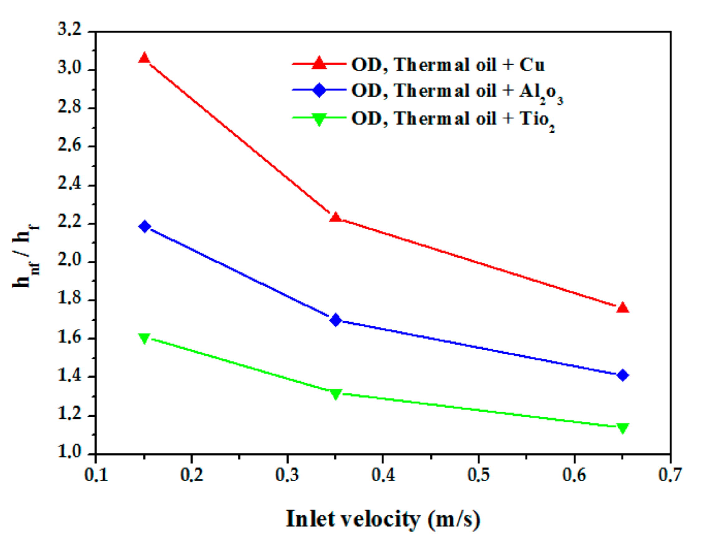
4. Effect of Different Types of Nanoparticles
5. Conclusions
- The RNG k- ε model is adopted to compute the turbulent motion in the absorber tube of PTR as it gives the minimum error when compared to the literature.
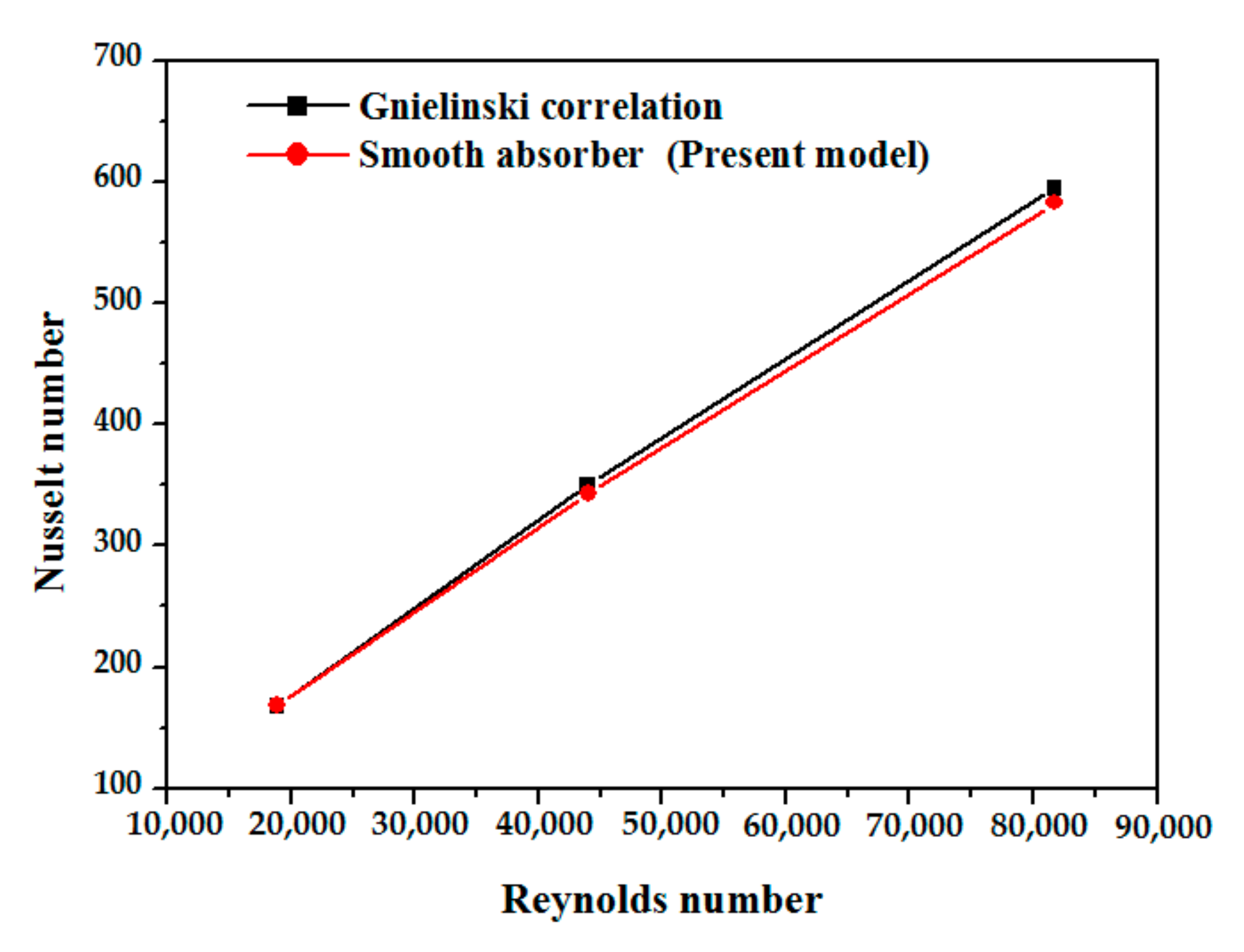
- The obtained friction factor and Nusselt number showed good agreement with Petukhov and Gnielinski equation correlations.
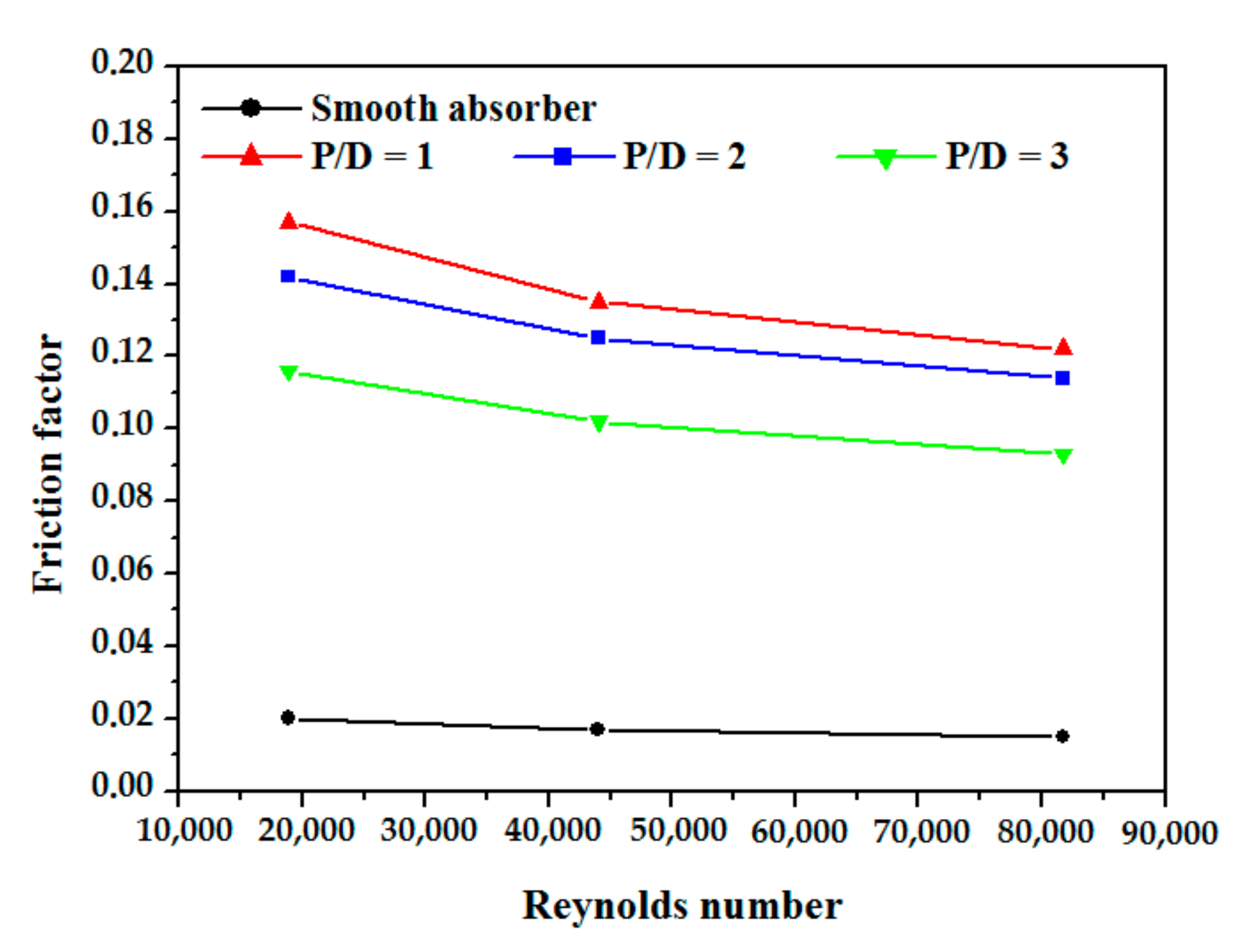
- The usage of obstacles in the absorber tube has a favorable influence on Nusselt number, and adverse effect on friction factor.
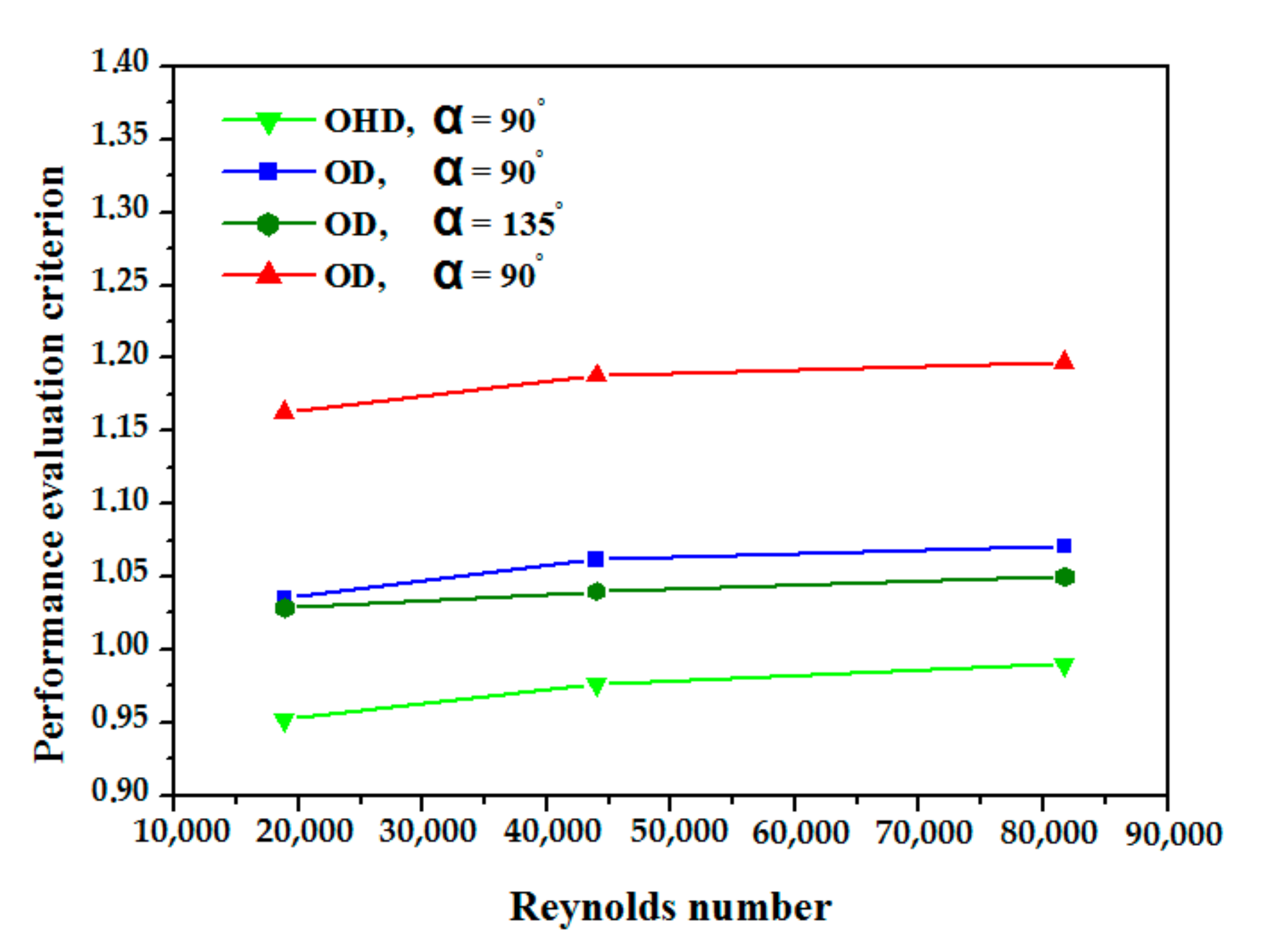
- Compared to the reference case, the highest improvement in Nusselt number was 129% which was achieved by the obstacles discs (α = 90°), followed by 95% for the obstacles discs (OD, α = 45° and α = 135°), while the obstacles half discs (α = 90°) achieved the lowest improvement of only 79%.
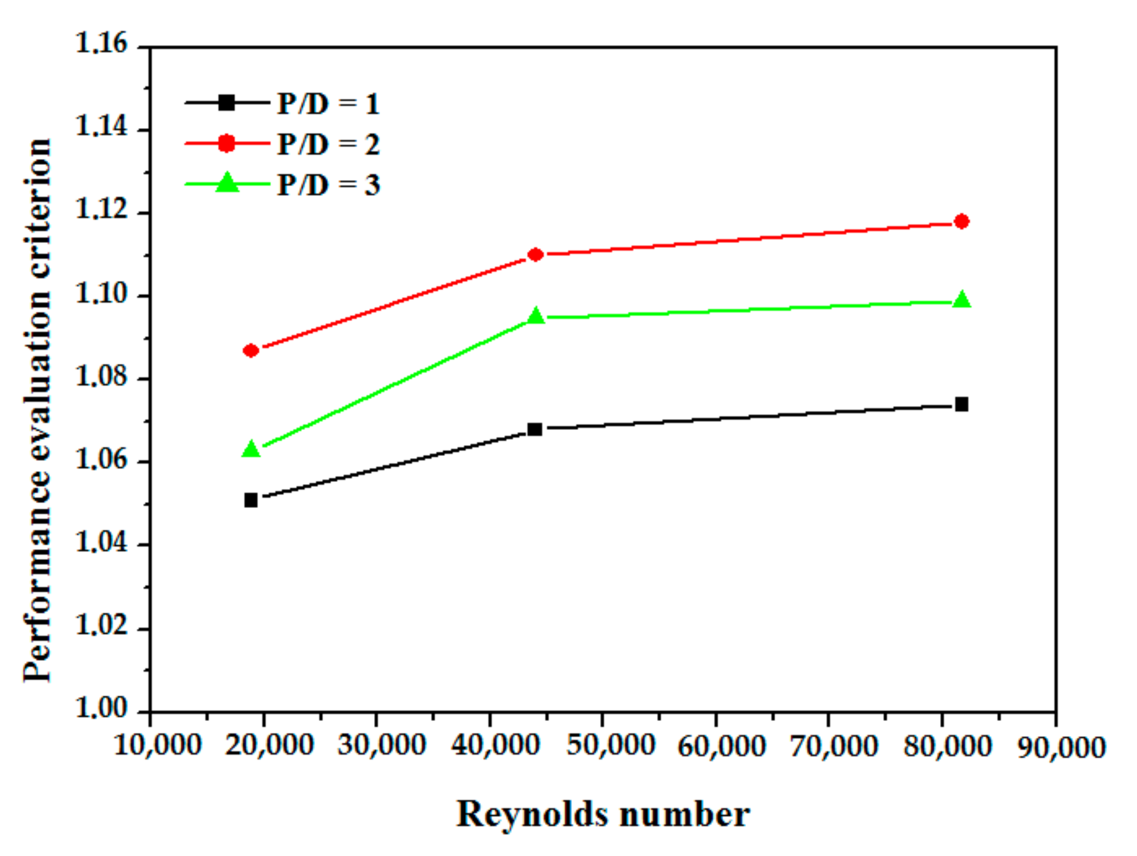
- The friction factor is inversely proportional to the value of P/D.
- The optimum thermal performance is obtained when the absorber tube with obstacles discs (α = 90°) and P/D = 2.
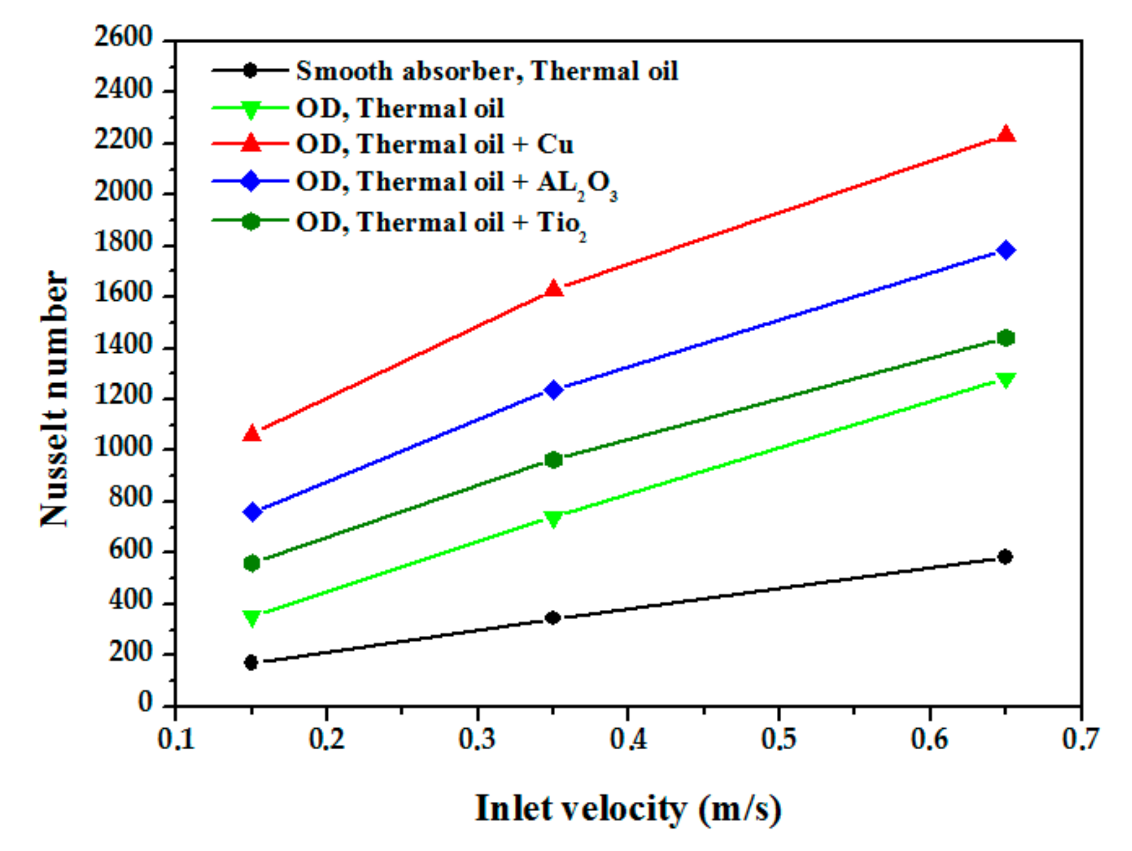
- Heat transfer is significantly augmented when using nanofluids.
- The use of Cu nanoparticles resulted in the best thermal performance compared to Al2O3 and TiO2.
Author Contributions
Funding
Institutional Review Board Statement
Informed Consent Statement
Data Availability Statement
Conflicts of Interest
Nomenclature
| Cp | Specific heat capacity, (J/kg.K) | ν | Kinematic viscosity, (m2/s) |
| D | Absorber tube inner diameter, (m) | ρ | Density, (kg/m3) |
| d | Diameter of obstacle, (m) | τw | Wall shear stress, (Pa) |
| f | Friction factor | ϕ | Nanoparticle volume fraction, % |
| h | Heat transfer Coefficient, (W/m2.K) | φ | Circumferential angle, (°) |
| L | Tube length, (m) | Subscripts | |
| ṁ | Mass flow reat, (kg/sec) | avg | Average |
| Nu | Nusselt number | b | Bottom |
| P | Distance between the obstacles, (m) | cal | Calculated |
| P | Pressure, (Pa) | D | Hydraulic diameter |
| ∆P | Pressure drop, (Pa) | exp | Experiment |
| Pr | Prandtl number | f | Fluid |
| q | Heat flux, (W/m2) | in | Inlet |
| Re | Reynolds number | max | Maximum |
| T | Temperature, (K) | min | Minimum |
| v | Velocity, (m/s) | nf | Nanofluid |
| Greek symbols | np | Nanoparticle | |
| α | Inclination angle of the obstacles, (°) | t | Top |
| δ | Deviation, (%) | x, y, z | Cartesian coordinates |
| ε | Rate of dissipation of turbulent kinetic energy | Abbreviation | |
| k | Turbulent kinetic energy, (J/kg) | DISS | Direct Solar Steam |
| λ | Conductivity, (W/m.K) | DNI | Direct normal irradiance |
| HTF | Heat transfer fluid | PEC | Performance evaluation criteria |
| LCR | Local concentration ratio | PTC | Parabolic trough collector |
| MCRT | Monte Carol ray-tracing | PTR | Parabolic trough receiver |
| OD | Obstacles discs | RNG | Renormalization-group |
| OHD | Obstacles half discs | ||
References
- Zandalinas, S.I.; Fritschi, F.B.; Mittler, R. Global Warming, Climate Change, and Environmental Pollution: Recipe for a Multifactorial Stress Combination Disaster. Trends Plant Sci. 2021, 26, 588–599. [Google Scholar] [CrossRef] [PubMed]
- Wu, X.; Deng, H.; Li, H.; Guo, Y. Impact of Energy Structure Adjustment and Environmental Regulation on Air Pollution in China: Simulation and Measurement Research by the Dynamic General Equilibrium Model. Technol. Forecast. Soc. Change 2021, 172, 121010. [Google Scholar] [CrossRef]
- Jamshed, W.; Eid, M.R.; Aissa, A.; Mourad, A.; Nisar, K.S.; Shahzad, F.; Saleel, C.A.; Vijayakumar, V. Partial velocity slip effect on working magneto non-Newtonian nanofluids flow in solar collectors subject to change viscosity and thermal conductivity with temperature. PLoS ONE 2021, 16, e0259881. [Google Scholar] [CrossRef] [PubMed]
- Shahzad, F.; Jamshed, W.; Sathyanarayanan, S.U.D.; Aissa, A.; Madheshwaran, P.; Mourad, A. Thermal analysis on Darcy-Forchheimer swirling Casson hybrid nanofluid flow inside parallel plates in parabolic trough solar collector: An application to solar aircraft. Int. J. Energy Res. 2021, 45, 20812–20834. [Google Scholar] [CrossRef]
- Sayed, E.T.; Wilberforce, T.; Elsaid, K.; Rabaia, M.K.H.; Abdelkareem, M.A.; Chae, K.-J.; Olabi, A. A critical review on environmental impacts of renewable energy systems and mitigationstrategies: Wind, hydro, biomass and geothermal. Sci. Total Environ. 2020, 766, 144505. [Google Scholar] [CrossRef]
- Pandey, A.; Kumar, R.R.; Kalidasan, B.; Laghari, I.A.; Samykano, M.; Kothari, R.; Abusorrah, A.M.; Sharma, K.; Tyagi, V. Utilization of solar energy for wastewater treatment: Challenges and progressive research trends. J. Environ. Manag. 2021, 297, 113300. [Google Scholar] [CrossRef]
- Radouane, F.; Abderrahmane, A.; Mebarek-Oudina, F.; Ahmed, W.; Rashad, A.M.; Sahnoun, M.; Ali, H.; Ali, H.M. Magneto-free convectiveof hybrid nanofluid inside non-darcy porous enclosure containing an adiabatic rotating cylinder. Energy Sources Part A Recovery Util. Environ. Eff. 2020, 136, 1–16. [Google Scholar]
- Mourad, A.; Aissa, A.; Mebarek-Oudina, F.; Al-Kouz, W.; Sahnoun, M. Natural convection of nanoliquid from elliptic cylinder in wavy enclosure under the effect of uniform magnetic field: Numerical investigation. Eur. Phys. J. Plus 2021, 136, 429. [Google Scholar] [CrossRef]
- Chiemelu, N.E.; Anejionu, O.C.; Ndukwu, R.I.; Okeke, F.I. Assessing the potentials of largescale generation of solar energy in Eastern Nigeria with geospatial technologies. Sci. Afr. 2021, 12, e00771. [Google Scholar] [CrossRef]
- Aman, M.; Solangi, K.; Hossain, M.; Badarudin, A.; Jasmon, G.; Mokhlis, H.; Bakar, A.; Kazi, S. A review of Safety, Health and Environmental (SHE) issues of solar energy system. Renew. Sustain. Energy Rev. 2015, 41, 1190–1204. [Google Scholar] [CrossRef]
- Han, Y.; Sun, Y.; Wu, J. A low-cost and efficient solar/coal hybrid power generation mode: Integration of non-concentrating solar energy and air preheating process. Energy 2021, 235, 12136. [Google Scholar] [CrossRef]
- Pal, R.K.; Kumar, R. Investigations of thermo-hydrodynamics, structural stability, and thermal energy storagefor direct steam generation in parabolic trough solar collector: A comprehensive review. J. Clean. Prod. 2021, 311, 127550. [Google Scholar] [CrossRef]
- Alotaibi, S.; Alotaibi, F.; Ibrahim, O.M. Solar-assisted steam power plant retrofitted with regenerative system using Parabolic Trough Solar Collectors. Energy Rep. 2020, 6, 124–133. [Google Scholar] [CrossRef]
- Sandá, A.; Moya, S.L.; Valenzuela, L. Modelling and simulation tools for direct steam generation in parabolic-trough solar collectors: A review. Renew. Sustain. Energy Rev. 2019, 113, 109226. [Google Scholar] [CrossRef]
- Forristall, R. Heat Transfer Analysis and Modeling of a Parabolic Trough Solar Receiver Implemented in Engineering Equation Solver; Technical Report; Renewable Energy Laboratory: Golden, CO, USA, 2003. [Google Scholar] [CrossRef] [Green Version]
- Mao, Q.; Shuai, Y.; Yuan, Y. Study on radiation flux of the receiver with a parabolic solar concentrator system. Energy Convers. Manag. 2014, 84, 1–6. [Google Scholar] [CrossRef]
- Petrasch, J. A free and open source Monte Carlo ray tracing program for concentrating solar energy research. Energy Sustain. 2010, 43956, 125–132. [Google Scholar]
- Cheng, Z.; He, Y.; Xiao, J.; Tao, Y.B.; Xu, R.J. Numerical study of heat transfer characteristics in the solar receiver tube combined with mcrt method. In Proceedings of the Inaugural US-EU-China Thermophysics Conference-Renewable Energy, Beijing, China, 28–30 May 2009. [Google Scholar]
- Cheng, Z.D.; He, Y.L.; Cui, F.Q.; Du, B.C.; Zheng, Z.J.; Xu, Y. Comparative and sensitive analysis for parabolic trough solar collectors with a detailed Monte Carlo ray-tracing optical model. Appl. Energy 2014, 115, 559–572. [Google Scholar] [CrossRef]
- Grena, R. Optical simulation of a parabolic solar trough collector. Int. J. Sustain. Energy 2010, 29, 19–36. [Google Scholar] [CrossRef]
- He, Y.L.; Xiao, J.; Cheng, Z.D.; Tao, Y.B. A MCRT and FVM coupled simulation method for energy conversionprocess in parabolic trough solar collector. Renew. Energy 2011, 36, 976–985. [Google Scholar] [CrossRef]
- Cheng, Z.D.; He, Y.L.; Cui, F.Q.; Xu, R.J.; Tao, Y.B. Numerical simulation of a parabolic trough solar collector with nonuniform solar flux conditions by coupling FVM and MCRT method. Sol. Energy 2012, 86, 1770–1784. [Google Scholar] [CrossRef]
- Eck, M.; Feldhoff, J.F.; Uhlig, R. Thermal modelling and simulation of parabolic trough receiver tubes. Energy Sustain. 2010, 43956, 659–666. [Google Scholar]
- Wang, F.; Shuai, Y.; Yuan, Y.; Yang, G.; Tan, H. Thermal stress analysis of eccentric tube receiver using concentrated solar radiation. Sol. Energy 2010, 84, 1809–1815. [Google Scholar] [CrossRef]
- Sadegh Hosseini, S.M.; Dehaj, M.S. An experimental study on energetic performance evaluation of a parabolic trough solar collector operating with Al2O3/water and GO/water nanofluids. Energy 2021, 234, 121317. [Google Scholar] [CrossRef]
- Zhao, Z.; Bai, F.; Zhang, X.; Wang, Z. Experimental study of pin finned receiver tubes for a parabolic trough solar air collector. Sol. Energy 2020, 207, 91–102. [Google Scholar] [CrossRef]
- Norouzi, A.M.; Siavashi, M.; Ahmadi, R.; Tahmasbi, M. Experimental study of a parabolic trough solar collector with rotating absorber tube. Renew. Energy 2021, 168, 734–749. [Google Scholar] [CrossRef]
- Al Loni, R.; Asli-Ardeh, E.A.; Ghobadian, B.; Kasaeian, A.B.; Gorjian, S. Thermodynamic analysis of a solar dish receiver using different nanofluids. Energy 2017, 133, 749–760. [Google Scholar] [CrossRef]
- Ham, J.; Kim, J.; Cho, H. Theoretical analysis of thermal performance in a plate type liquid heat exchange rusing various nanofluids based on LiBr solution. Appl. Therm. Eng. 2016, 108, 1020–1032. [Google Scholar] [CrossRef]
- Mwesigye, A.; Huan, Z.; Meyer, J.P. Thermodynamic optimisation of the performance of a parabolic trough receiver using synthetic oil–Al2O3 nanofluid. Appl. Energy 2015, 156, 398–412. [Google Scholar] [CrossRef] [Green Version]
- Mwesigye, A.; Meyer, J.P. Optimal thermal and thermodynamic performance of a solar parabolic trough receiver with different nanofluids and at different concentration ratios. Appl. Energy 2017, 193, 393–413. [Google Scholar] [CrossRef] [Green Version]
- Bellos, E.; Tzivanidis, C.; Tsimpoukis, D. Enhancing the performance of parabolic trough collectors using nanofluids and turbulators. Renew. Sustain. Energy Rev. 2018, 91, 358–375. [Google Scholar] [CrossRef]
- Mohammed, H.A.; Vuthaluru, H.B.; Liu, S. Heat transfer augmentation of parabolic trough solar collector receiver’s tube using hybrid nanofluids and conical turbulators. J. Taiwan Inst. Chem. Eng. 2021, 125, 215–242. [Google Scholar] [CrossRef]
- Liu, P.; Dong, Z.; Xiao, H.; Liu, Z.; Liu, W. A novel parabolic trough receiver by inserting an inner tube with awing-like fringe for solar cascade heat collection. Renew. Energy 2021, 170, 327–340. [Google Scholar] [CrossRef]
- Manikandan, G.K.; Iniyan, S.; Goic, R. Enhancing the optical and thermal efficiency of a parabolic trough collector—A review. Appl. Energy 2019, 235, 1524–1540. [Google Scholar] [CrossRef]
- Jaramillo, O.A.; Borunda, M.; Velazquez-Lucho, K.M.; Robles, M. Parabolic trough solar collector for low enthalpy processes: An analysis of the efficiency enhancement by using twisted tape inserts. Renew. Energy 2016, 93, 125–141. [Google Scholar] [CrossRef]
- Amina, B.; Miloud, A.; Samir, L.; Abdelylah, B.B.; Solano, J.P. Heat transfer enhancement in a parabolic trough solar receiver using longitudinal fins and nanofluids. J. Therm. Sci. 2016, 25, 410–417. [Google Scholar] [CrossRef]
- Kumar, K.R.; Reddy, K.S. Thermal analysis of solar parabolic trough with porous disc receiver. Appl. Energy 2009, 86, 1804–1812. [Google Scholar] [CrossRef]
- Wang, F.; Tan, J.; Wang, Z. Heat transfer analysis of porous media receiver with different transport and thermophysical models using mixture as feeding gas. Energy Convers. Manag. 2014, 83, 159–166. [Google Scholar] [CrossRef]
- Xiangtao, G.; Fuqiang, W.; Haiyan, W.; Tan, J.; Lai, Q.; Han, H. Heat transfer enhancement analysis of tube receiver for parabolic trough solar collector with pin fin arrays inserting. Sol. Energy 2017, 144, 185–202. [Google Scholar]
- Huang, Z.; Li, Z.-Y.; Yu, G.-L.; Tao, W.-Q. Numerical investigations on fully-developed mixed turbulent convection in dimpled parabolic trough receiver tubes. Appl. Therm. Eng. 2017, 114, 1287–1299. [Google Scholar] [CrossRef]
- Ebrahim, S.E.; Ranjbar, A.A. Numerical thermal study on effect of porous rings on performance of solar parabolic trough collector. Appl. Therm. Eng. 2017, 118, 807–816. [Google Scholar] [CrossRef]
- Benabderrahmane, A.; Benazza, A.; Laouedj, S.; Solano, J.P. Numerical analysis of compound heat transfer enhancement by single and two-phase models in parabolic through solar receiver. Mechanika 2017, 23, 55–61. [Google Scholar] [CrossRef] [Green Version]
- Bellos, E.; Tzivanidis, C.; Antonopoulos, K.A.; Gkinis, G. Thermal enhancement of solar parabolic trough collectors by using nanofluids and converging-diverging absorber tube. Renew. Energy 2016, 94, 213–222. [Google Scholar] [CrossRef]
- Benabderrahmane, A.; Benazza, A.; Hussein, A.K. Heat Transfer Enhancement Analysis of Tube Receiver for Parabolic Trough Solar Collector With Central Corrugated Insert. J. Heat Transfer. 2020, 142, 062001. [Google Scholar] [CrossRef]
- Bellos, E.; Tzivanidis, C.; Daniil, I.; Kimon, A.; Antonopoulos, K.A. The impact of internal longitudinal fins in parabolic trough collectors operating with gases. Energy Convers. Manag. 2017, 135, 35–54. [Google Scholar] [CrossRef]
- Mwesigye, A.; Ochende, T.; Meyer, J.P. Heat transfer and thermodynamic performance of a parabolic trough receiver with centrally placed perforated plate inserts. Appl. Energy 2014, 136, 989–1003. [Google Scholar] [CrossRef] [Green Version]
- Wang, P.; Liu, D.Y.; Xu, C. Numerical study of heat transfer enhancement in the receiver tube of direct steam generation with parabolic trough by inserting metal foams. Appl. Energy 2013, 102, 449–460. [Google Scholar] [CrossRef]
- Cheng, Z.D.; He, Y.L.; Cui, F.Q. Numerical study of heat transfer enhancement by unilateral longitudinal vortex generators inside parabolic trough solar receivers. Int. J. Heat Mass Transf. 2012, 55, 5631–5641. [Google Scholar] [CrossRef]
- Saha, S.K.; Dutta, A.; Dhal, S.K. Friction and heat transfer characteristics of laminar swirl flow through a circular tube fitted with regularly spaced twisted-tape elements. Int. J. Heat Mass Transf. 2001, 44, 4211–4223. [Google Scholar] [CrossRef]
- Wang, F.Q.; Tan, J.Y.; Ma, L.X.; Wang, C.C. Effects of glass cover on heat flux distribution for tube receiver with parabolic trough collector system. Energy Convers. Manag. 2015, 90, 47–52. [Google Scholar]
- Wu, Z.Y.; Li, S.D.; Yuan, G.F.; Lei, D.Q.; Wang, Z.F. Three-dimensional numerical study of heat transfer characteristics of parabolic trough receiver. Appl. Energy 2014, 113, 902–911. [Google Scholar] [CrossRef]
- Wu, Z.Y.; Lei, D.Q.; Yuan, G.F.; Shao, J.J.; Zhang, Y.T.; Wang, Z.F. Structural reliability analysis of parabolic trough receivers. Appl. Energy 2014, 123, 232–241. [Google Scholar] [CrossRef]
- Hachicha, A.A.; Rodriguez, I.; Capdevila, R.; Oliva, A. Heat transfer analysis and numerical simulation of a parabolic trough solar collector. Appl. Energy 2013, 111, 581–592. [Google Scholar] [CrossRef] [Green Version]
- Solutia. Combined Heating & Cooling Highly Stable Heat Transfer Fluid. Heat Transfer Fluids by SOLUTIA. Applied Chemistry, Creative Solution. GROUP PROVOC T.B.S 10-19 (12/98) E. 1998. Available online: http://twt.mpei.ac.ru/TTHB/HEDH/HTF-D12.PDF (accessed on 12 December 2021).
- Roldán, M.I.; Valenzuela, L.; Zarza, E. Thermal analysis of solar receiver pipes with superheated steam. Appl. Energy 2013, 73, 73–84. [Google Scholar] [CrossRef]
- Gee, D.L.; Webb, R.L. Forced convection heat transfer in helically rib-roughened tubes. Int. Heat Mass Transf. 1980, 23, 1127–1136. [Google Scholar] [CrossRef]
- Gnielinski, V. New equations for heat and mass-transfer in turbulent pipe and channel flow. Int. J. Chem. Eng. 1976, 16, 359.e68. [Google Scholar]
- Petukhov, B.S. Heat transfer and friction in turbulent pipe flow with variable physical properties. In Advances in Heat Transfer; Petukhov, B.S., Irvine, T.F., Hartnett, J.P., Eds.; Elsevier: Amsterdam, The Netherlands, 1970; Volume 6, pp. 503–564. [Google Scholar]
- Zhang, X.; Gu, H.; Fujii, M. Effective thermal conductivity and thermal diffusivity of Nanofluids containing spherical and cylindrical nanoparticles. Exp. Therm. Fluid Sci. 2007, 31, 593–599. [Google Scholar] [CrossRef]
- Brinkman, H.C. The viscosity of concentrated suspensions and solution. J. Chem. Phys. 1952, 20, 571–581. [Google Scholar] [CrossRef]
- Maxwell, J.C. A Treatise on Electricity and Magnetism, 3rd ed.; Clarendon Press: Oxford, UK, 1891; pp. 435–441. [Google Scholar]
- Xuan, Y.; Roetzel, W. Conception for Heat Transfer Correlation of Nanofluids. Int. J. Heat Mass Transf. 2000, 43, 3701–3707. [Google Scholar] [CrossRef]


| Parameter | Values |
|---|---|
| Reflector/Absorber Length | 4.06 m |
| Metal Tube Inner Diameter | 0.067 m |
| Metal Tube Outer Diameter | 0.07 m |
| Glass Cover Inner Diameter | 0.117 m |
| Glass Cover Outer Diameter | 0.12 m |
| Parabolic Trough Concentrator Reflectivity | 0.9 |
| Glass envelope Transmissivity | 0.96 |
| Metal Tube Absorptivity | 8027 kg/m3 |
| Metal Tube Thermal Conductivity | 20 W/m.k |
| Metal Tube Specific heat | 500 J/kg.k |
| Case | Pin (MPa) | Tin (K) | DNI (W/m2) | ṁ (Kg/s) |
|---|---|---|---|---|
| 1 | 6.0 | 557.5 | 838 | 0.73 |
| 2 | 6.1 | 598.1 | 761 | 0.62 |
| 3 | 6.0 | 607.3 | 635 | 0.55 |
| 4 | 6.0 | 613 | 627 | 0.56 |
| 5 | 6.0 | 632.9 | 635 | 0.55 |
| 6 | 6.0 | 643 | 627 | 0.56 |
| Case | 1 | 2 | 3 | 4 | 5 | 6 |
|---|---|---|---|---|---|---|
| Experimental results “Roldàn et al. [56]” | ||||||
| Tmax | 604.7 | 649.1 | 647 | 646.8 | 681.6 | 681.5 |
| Tmin | 571.4 | 616.6 | 612.2 | 612.2 | 646.8 | 646.4 |
| Standard k-ɛ model | ||||||
| Tmax | 603.5 | 639.92 | 642.21 | 647.46 | 667.75 | 677.39 |
| δ | 0.18 | 1.41 | 0.74 | 0.1 | 2.03 | 0.6 |
| δmoyen | 0.84 | |||||
| Tmin | 558.61 | 599.1 | 608.13 | 613.82 | 633.74 | 643.83 |
| δ | 2.23 | 2.83 | 0.66 | 0.26 | 2.01 | 0.39 |
| δmoyen | 1.39 | |||||
| Realizable k-ɛ model | ||||||
| Tmax | 603.6 | 639.95 | 642.23 | 647.48 | 667.78 | 677.42 |
| δ | 0.18 | 1.4 | 0.73 | 0.1 | 2.02 | 0.59 |
| δmoyen | 0.83 | |||||
| Tmin | 558.59 | 599.09 | 608.12 | 613.81 | 633.73 | 643.82 |
| δ | 2.24 | 2.83 | 0.66 | 0.26 | 2.02 | 0.39 |
| δmoyen | 1.4 | |||||
| RNG k-ɛ model | ||||||
| Tmax | 603.69 | 640.02 | 642.29 | 647.54 | 667.84 | 677.48 |
| δ | 0.16 | 1.39 | 0.72 | 0.11 | 2.01 | 0.58 |
| δmoyen | 0.82 | 599.06 | 608.1 | 613.79 | 633.7 | 643.82 |
| Tmin | 558.59 | 599.06 | 608.1 | 613.79 | 633.7 | 643.82 |
| δ | 2.24 | 2.84 | 0.66 | 0.25 | 2.02 | 0.4 |
| δmoyen | 1.4 | |||||
| Ncells | |||||
|---|---|---|---|---|---|
| 294,600 | 307,200 | 330,400 | 354,400 | ||
| Re | Nu | |δmax| | |||
| 104 | 148.123 | 150.021 | 149.613 | 150.461 | 1.57% |
| 105 | 222.104 | 226.371 | 226.719 | 229.004 | 3.10% |
| 106 | 259.121 | 258.223 | 259.942 | 260.781 | 0.64% |
Publisher’s Note: MDPI stays neutral with regard to jurisdictional claims in published maps and institutional affiliations. |
© 2022 by the authors. Licensee MDPI, Basel, Switzerland. This article is an open access article distributed under the terms and conditions of the Creative Commons Attribution (CC BY) license (https://creativecommons.org/licenses/by/4.0/).
Share and Cite
Fahim, T.; Laouedj, S.; Abderrahmane, A.; Alotaibi, S.; Younis, O.; Ali, H.M. Heat Transfer Enhancement in Parabolic through Solar Receiver: A Three-Dimensional Numerical Investigation. Nanomaterials 2022, 12, 419. https://doi.org/10.3390/nano12030419
Fahim T, Laouedj S, Abderrahmane A, Alotaibi S, Younis O, Ali HM. Heat Transfer Enhancement in Parabolic through Solar Receiver: A Three-Dimensional Numerical Investigation. Nanomaterials. 2022; 12(3):419. https://doi.org/10.3390/nano12030419
Chicago/Turabian StyleFahim, Tayeb, Samir Laouedj, Aissa Abderrahmane, Sorour Alotaibi, Obai Younis, and Hafiz Muhammad Ali. 2022. "Heat Transfer Enhancement in Parabolic through Solar Receiver: A Three-Dimensional Numerical Investigation" Nanomaterials 12, no. 3: 419. https://doi.org/10.3390/nano12030419
APA StyleFahim, T., Laouedj, S., Abderrahmane, A., Alotaibi, S., Younis, O., & Ali, H. M. (2022). Heat Transfer Enhancement in Parabolic through Solar Receiver: A Three-Dimensional Numerical Investigation. Nanomaterials, 12(3), 419. https://doi.org/10.3390/nano12030419