Article

Effect of Carbon Nanofiber Clustering on the Micromechanical Properties of a Cement Paste

1
Department of Civil and Environmental Engineering, Vanderbilt University, Nashville, TN 37212, USA
2
International Research Office, U.S. Army Engineer Research and Development Center, Ruislip HA4 7HB, UK
3
Department of Mechanical Engineering, The University of Alabama, Tuscaloosa, AL 35401, USA
*
Author to whom correspondence should be addressed.
Nanomaterials 2022, 12(2), 223; https://doi.org/10.3390/nano12020223
Submission received: 18 November 2021 / Revised: 20 December 2021 / Accepted: 6 January 2022 / Published: 10 January 2022
(This article belongs to the Special Issue Concrete under Nanoscope)

Abstract

:
The use of carbon nanofibers (CNFs) in cement systems has received significant interest over the last decade due to their nanoscale reinforcing potential. However, despite many reports on the formation of localized CNF clusters, their effect on the cement paste micromechanical properties and relation to the mechanical response at the macroscopic scale are still not fully understood. In this study, grid nanoindentation coupled with scanning electron microscopy and energy dispersive spectroscopy was used to determine the local elastic indentation modulus and hardness of a portland cement paste containing 0.2% CNFs with sub-micro and microscale CNF clusters. The presence of low stiffness and porous assemblage of phases (modulus of 15–25 GPa) was identified in the cement paste with CNFs and was attributed primarily to the interfacial zone surrounding the CNF clusters. The CNFs favored the formation of higher modulus C–S–H phases (>30 GPa) in the bulk paste at the expense of the lower stiffness C–S–H. Nanoindentation results combined with a microscale–macroscale upscaling homogenization method further revealed an elastic modulus of the CNF clusters in the range from 18 to 21 GPa, indicating that the CNF clusters acted as compliant inclusions relative to the cement paste.

1. Introduction

Carbon nanofibers (CNFs) are excellent candidates for reinforcement of cementitious materials at the nanoscale due to their unique characteristics (high aspect ratio with nanoscale diameters, and lengths of a few hundred nm to a few hundred µm; high strength; low density; and corrosion resistance) [1,2,3]. In addition to enhancing the mechanical properties and durability of cement-based materials, CNFs can perform new functions, such as stress-sensing, temperature monitoring, and electromagnetic shielding [4,5,6,7,8,9,10,11,12]. Potential applications of CNFs in cement-based materials include infrastructure health monitoring, traffic monitoring, and where low density-high performance materials are important. While there have been reports that the addition of CNFs can provide sub-micron crack bridging [13,14,15,16] and increase the amount of high-density C–S–H [17], the full reinforcing potential of the CNFs has largely been hindered by difficulties dispersing the CNFs in the cement matrix. Agglomerations of CNFs have been shown to form as localized sub-micro- and microscale clusters within the cement matrix due to the ubiquitous van der Waals forces and the unique environment of the hydrating cement paste (high pH, ionic composition, and cement grain size) [13,15,18,19,20,21]. While the occurrence of CNF clustering may often be viewed as a flaw or imperfection (i.e., randomly oriented, individually embedded CNFs with a uniform spatial arrangement would typically provide better load transfer than clustered CNFs), it may be beneficial in some situations. For example, clustering has been shown for polymer composites to enhance certain mechanical properties, including fracture toughness and damage tolerance [22], and to improve the formation of a percolating network for electrical conductivity [5,23,24]. Similar results for cementitious composites have been reported with a lower electrical resistance change due to micro-cracking observed in the presence of agglomerated carbon nanotubes (CNTs) compared to well-dispersed CNTs, suggesting that controlled agglomeration of CNFs/CNTs may be desirable depending on the application [5]. CNF clusters have also been found to create localized porosity [25] while providing a reinforcing network that has been reported by the authors to influence the macroscale flexural response [13] and delay cracking and spalling during sulfate-induced degradation [14]. Many studies have focused on the macroscale mechanical, physical, and electrical properties of CNT/CNF-modified cement pastes [4,6,7,9,10,22,26,27,28,29,30,31,32,33,34,35,36,37,38,39,40,41,42,43,44,45,46], but few studies have related the macroscale response to the dispersion state(s) of the CNFs [8,13,15,20,47,48,49,50]. As a result, the local influence of the CNFs, CNF clusters, and their interface with the surrounding matrix on the microstructure and mechanical behavior of the cement paste is not well understood. Given that CNF clusters might be inevitable in the cement matrix, possibly desirable for some applications, and their expected role in the mechanical properties and performance of CNF-modified cement pastes, the goal of this study was to evaluate the effect of CNF clustering on the cement paste micromechanical properties in order to better understand the structure–property relationships between the CNFs, CNF clusters, and the cement paste. Understanding these relationships provides direction for developing strategies in tuning the mechanical properties of the composite. Additionally, knowledge of the micromechanical properties of CNF clusters can provide insight into their stability under mechanical stress and thus inform mechanical dispersion methods.
The specific objectives of this paper were to (i) characterize the effect of CNFs and CNF clusters on the local micromechanical properties of a cement paste, (ii) correlate the micromechanical properties to microstructural and chemical properties, and (iii) link the microscale behavior with the overall mechanical response of a CNF-modified cement paste. Grid nanoindentation coupled with scanning electron microscopy (SEM)/energy dispersive spectroscopy (EDS) was used to determine the local elastic indentation modulus and hardness of a cement paste containing 0.2% CNFs with CNF clusters. Grid nanoindentation was chosen for this study as it provided a means of characterizing both the bulk cement paste and the areas surrounding the CNF clusters while avoiding a bias in the selection of the indent locations, which is important in the presence of a heterogeneous distribution of phases and inclusions at various length scales. Grid nanoindentation relies on a large number of indents and statistical deconvolution of experimental data to extract the mechanical properties of mechanically distinct phases and has been shown in the literature to be the method of choice for heterogeneous materials, such as cement pastes [51,52,53,54,55,56,57]. In addition, statistical analysis of the results provides information regarding the distribution and volume fraction of the mechanical material phases derived from the deconvolution process that are then used as input information for upscaling the micromechanical properties to the macroscale. A statistical Gaussian fitting method was used to segment the nanoindentation data into mechanically distinct phases. Grid nanoindentation was supplemented by backscattered electron (BSE) image analysis and energy dispersive spectroscopy (EDS) analysis at each nanoindentation location to relate the mechanical phases identified statistically by Gaussian deconvolution to the chemical phases present in the microstructure and to thus provide quality control of the data set. In addition, to further identify the nanoscale reinforcing behavior of the CNF clusters and their influence on the macroscale, a microscale–macroscale analytical upscaling approach described in [58] was applied to the nanoindentation dataset of the cement paste with CNFs. This approach has been shown, for an ordinary portland cement paste, to effectively upscale nanoindentation data at the microscale to the macroscale for comparison with macroscale mechanical measurement of the elastic modulus obtained via a pulse velocity method [58]. The paper provides new insights into the property–microstructure relations for CNF-modified cement pastes, particularly the effect of CNF agglomeration, and, to the best of the authors’ knowledge, reports for the first time, mechanical measurements of the interfacial zone between the CNF clusters and the cement matrix and estimated values of the elastic modulus of the CNF clusters. Significantly, the research demonstrated that grid nanoindentation with constitutive phase analysis combined with a micro–macroscale upscaling method is a valuable approach to estimate properties of inclusions that cannot be directly measured experimentally and to link the local micromechanical properties of a multiphase material that has randomly distributed inclusions at various length scales to its macroscopic mechanical response.

2. Materials and Methods

2.1. Cement Paste Preparation

Two cement pastes were prepared: a plain cement paste (reference cement paste) and a cement paste containing 0.2% CNFs per mass of cement (cement paste with CNFs). A dosage of 0.2% CNFs was selected for this study as it is in the median range of typical dosages found in the literature and was expected to demonstrate a range of CNF dispersion (i.e., individual fibers to microscale clusters). Type I/II Portland cement (Lafarge, Nashville, TN, USA) and Pyrograf® III PR 19 LHT CNFs (Applied Sciences, Inc., Cedarville, OH, USA) were used. Glenium® 7500 (BASF, Ludwigshafen, Germany), a polycarboxylate-based high range water reducer (HRWR), was used at a loading of 1% per mass of cement to promote the dispersion of the CNFs in the cement paste [20,26,59]. A water to cement (w/c) ratio of 0.28 was used for all mixes. The HRWR, CNFs (where applicable), and water were combined and sonicated with a bath sonicator (Aquasonic model 250D, VWR International, Radnor, PA, USA) for 30 min prior to mixing with the cement powder. After mixing, the paste was poured into 2.54 cm × 2.54 cm × 69 cm (H × W × L) beam molds and compacted by hand. The beams were de-molded after 24 h and kept at room temperature under 100% relative humidity for four years before testing.

2.2. Microscale Analysis

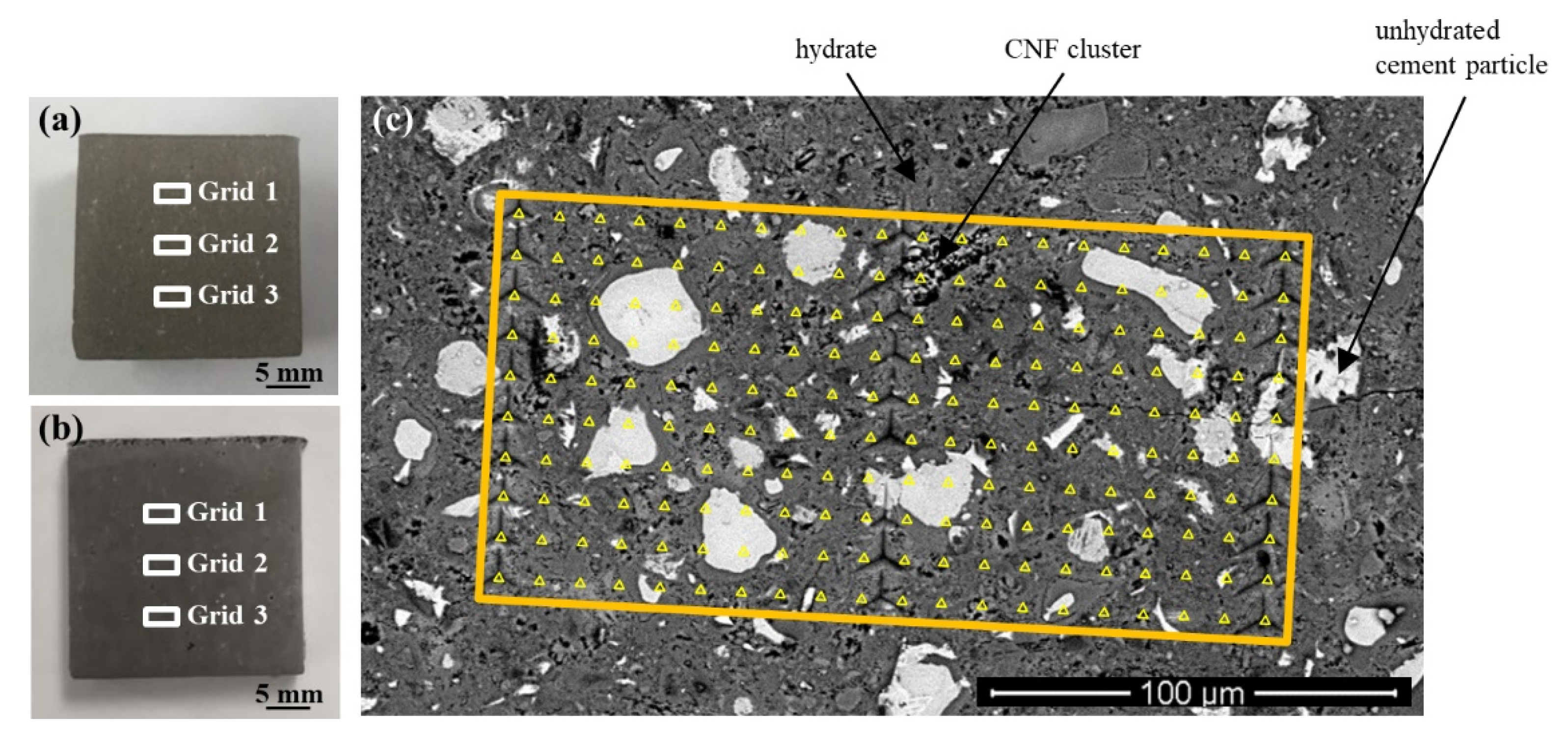
2.2.1. Grid Nanoindentation

Cement paste beams were cross-sectioned using a low-speed diamond saw, epoxy-mounted, and polished. Details of the mounting and polishing procedure can be found in [58]. The polishing procedure resulted in an average sample surface roughness (Ra) of 40–60 nm for a scan size of 25 µm × 25 µm, as measured by scanning probe microscopy. This average sample surface roughness has been reported in the literature to be adequate for the indentation of cement phases with a penetration depth of 200–300 nm [51,56,60,61,62,63,64,65,66]. A diamond Berkovich tip and an Agilent Nanoindenter G200 Testing System (Agilent Technologies, Santa Clara, CA, USA) were used to perform nanoindentation of the reference cement paste and cement paste with CNFs. A fused silica standard with known mechanical properties and a second-order area function was used to calibrate the tip [67]. Nanoindentation was performed using a grid collecting technique in which a total of 600 indents (three grids of 200 indents) were collected on each cement paste (Figure 1). Indent spacing was 10 µm in both the X and Y directions. A spacing of 10 µm between indents has been shown to be sufficient in cementitious materials for preventing adjacent indents from influencing the next indentation result [51,52,56,61,66,68,69,70]. A maximum force of 2 mN was applied during a 10 s loading period, with a targeted strain rate of 0.050 s−1. A maximum load of 2 mN was selected as it targeted indentation depths ranging from 200 to 300 nm, which, according to the literature, allows the individual response of C–S–H to be captured while also overcoming the surface roughness of polished cementitious materials [71,72]. The maximum load was held for 15 s and followed by a 10 s unloading period. The beginning, middle, and end of each grid were marked with fiducial indents to provide for clear identification of the grid during SEM/EDS analysis. Each indentation curve was then evaluated individually, and abnormal curves due to cracking of the immediate surrounding sample area during testing or improper contact between the tip and sample were discarded so as not to interfere with the determination of the micromechanical properties (Figure S1). Curve abnormality was generally seen for the large CNF clusters that, by their nature (i.e., composed of an entangled mass of fibers versus a hard solid surface), violated the assumption of a hard, flat surface needed for their indentation. The invalid load–displacement curves from the CNF clusters were properly removed from the statistical analysis per the accepted data evaluation for nanoindentation and were, therefore, not included in the determination of the micromechanical properties and were, instead, determined from a modeling procedure. Even after abnormal curve removal, over 400 valid indents were characterized for each cement paste. This number of indents has been reported to be sufficient for differentiating between primary cementitious phases (e.g., C–S–H, CH, or unhydrated cement particles) [66,71,73,74,75]. The indentation modulus and hardness of each valid indent were calculated using the Oliver and Pharr method [76], where Poisson’s ratio was assumed to be 0.3 for all calculations [77,78].

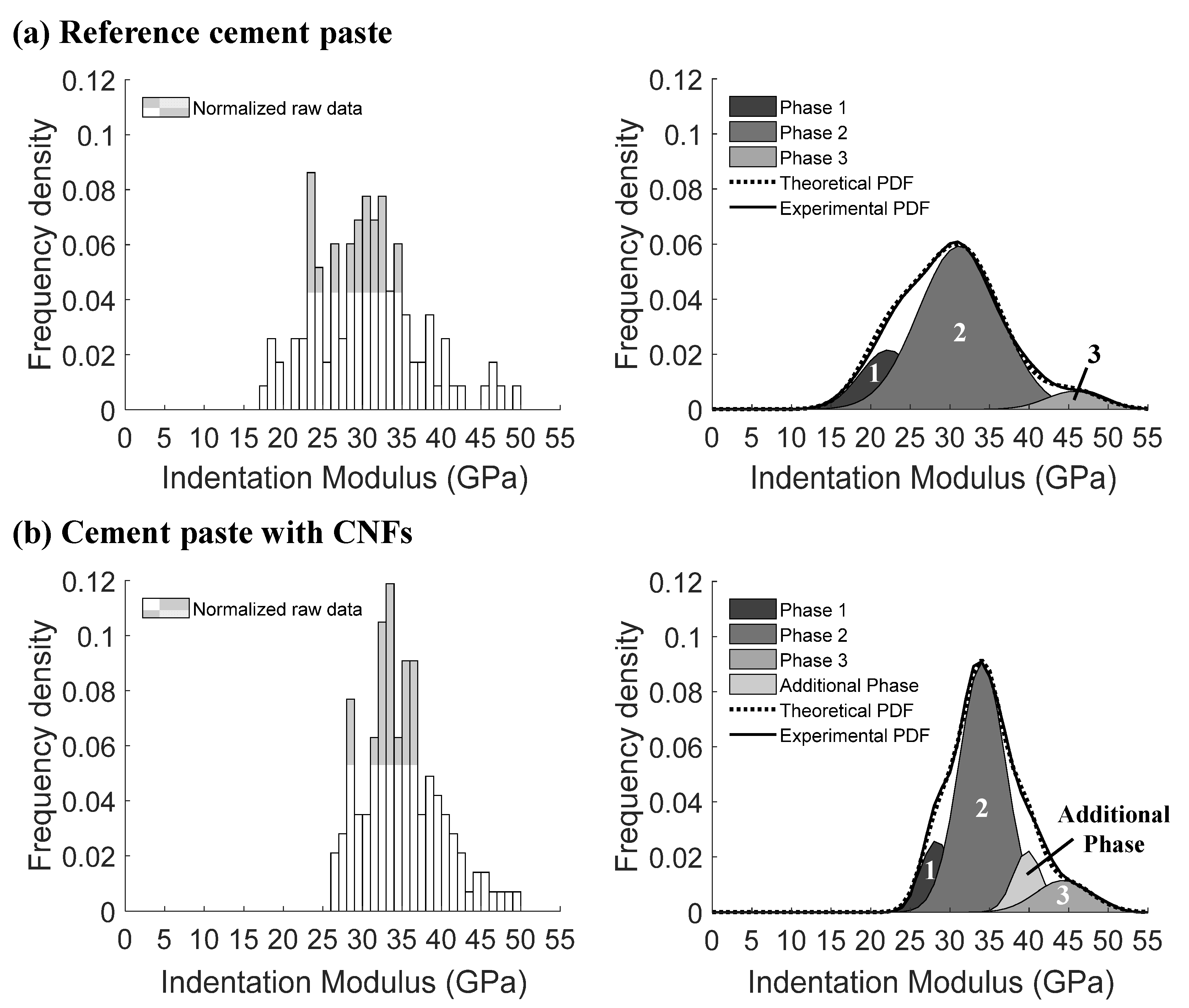
2.2.2. Gaussian Fitting Procedure

Each indentation modulus and hardness nanoindentation dataset was segmented into mechanically distinct phases using the statistical multimodal Gaussian fitting procedure used in [58]. The experimental probability density function (PDF) was plotted and fit with n Gaussian distributions. The parameters (i.e., mean, µ, and standard deviation, σ) for each fitted Gaussian distribution were then calculated, and the theoretical PDF based on the fitted Gaussian distributions was generated. The number of characteristic peaks in the experimental PDF was used to initially set the starting number of Gaussian distributions, n. A looping algorithm that allowed for multiple trials was coupled with an expectation maximization (EM) algorithm to determine different possible theoretical PDFs and to iteratively test for the appropriate number of Gaussian distributions. Only Gaussian distributions corresponding to the primary peaks of the experimental PDF (i.e., peaks composed of a minimum of 5% of the total indents) were considered for further analysis. A bin size of 1 GPa was used for all the Gaussian indentation modulus fits, which has been shown to be appropriate for cement pastes [56,79,80]. This bin size provided the best approximation of the raw data based on multiple bin sizes (0.1 to 10 GPa) examined (Figure S2). A discussion on the effect of the bin size can be found in [81,82]. A bin size of 0.1 GPa was used for all of the hardness fits [56]. The overall best fit (i.e., theoretical PDF) from all the trials was selected based on comparison to the experimental PDF by the Kullback–Leibler divergence [83,84]. As an additional verification of the final fit and bin size selection per [81], the theoretical and experimental cumulative density functions (CDFs) were also plotted and compared and are provided in Supplementary Materials (Figures S3 and S4).

2.2.3. Chemical and Microstructural Characterization

A coupled SEM/EDS analysis was used to identify the phase(s) present at each indent location—hydrates, unhydrated cement particles, flaws, or a combination of these. An environmental FEI Quanta FEG 650 high-resolution scanning electron microscope (FEI company, Hillsboro, OR, USA) equipped with a Schottky field emission gun, digital imaging, and an energy dispersive X-ray spectrometer was used to collect secondary (SE) and backscatter electron (BSE) images of the nanoindentation grid locations and chemical data at the location of each indent. A pressure of 130 Pa (in ESEM mode), accelerating voltage of 15 kV, spot size of 3.5, and a working distance of 10.5 mm were used.

2.3. Macroscale Analysis

2.3.1. Pulse Velocity Measurements of Elastic Modulus

The pulse velocity of the cement pastes was measured using a Pundit PL 200 with 150 kHz transducers (Proceq, Schwerzenbach, Zürich, Switzerland). Pulse velocity measurements are non-destructive tests that yield results that closely mimic the inherent Young’s modulus of the composite. The dynamic modulus of elasticity was calculated according to ASTM C597: Standard Test Method for Pulse Velocity through Concrete [85].

2.3.2. Microscale–Macroscale Analytical Homogenization

A homogenization approach based on the analytical Mori–Tanaka method [51,86] was employed to upscale the micromechanical properties obtained from grid nanoindentation to the macroscale and estimate the elastic modulus of the CNF clusters. The methodology used in the homogenization approach has been detailed in [58]. The mechanically distinct phases identified during the Gaussian fitting of the nanoindentation datasets were used to define the reference matrix and inclusions to be used in the Mori–Tanaka method. The volume fraction associated with porosity was estimated using SEM porosity analysis and then corrected for the fraction of porosity outside the SEM domain as described in [58]. The volume fractions of each mechanically distinct phase were determined from the results of the Gaussian fitting procedure and adjusted to account for the porosity. For the cement paste with CNFs, an additional phase was defined to account for the nanoscale reinforcing behavior of the CNF clusters (cluster pull-out, cluster crack deflection, etc.) [13]. This behavior could not be captured directly from experimental nanoindentation because of the nature of the CNF clusters—the random packing of the CNFs does not yield a hard, flat, stable surface that would be appropriate for surface indentation. A multi-step process was, therefore, employed to develop an acceptable cluster phase to characterize the CNF cluster micromechanical behavior in the homogenization approach. This process involved varying Poisson’s ratio of the CNF cluster phase to back-calculate the elastic modulus of the cluster phase in order to approximate an overall homogenized elastic modulus that corresponded to the experimentally measured elastic modulus of the cement paste with CNFs.

3. Results and Discussion

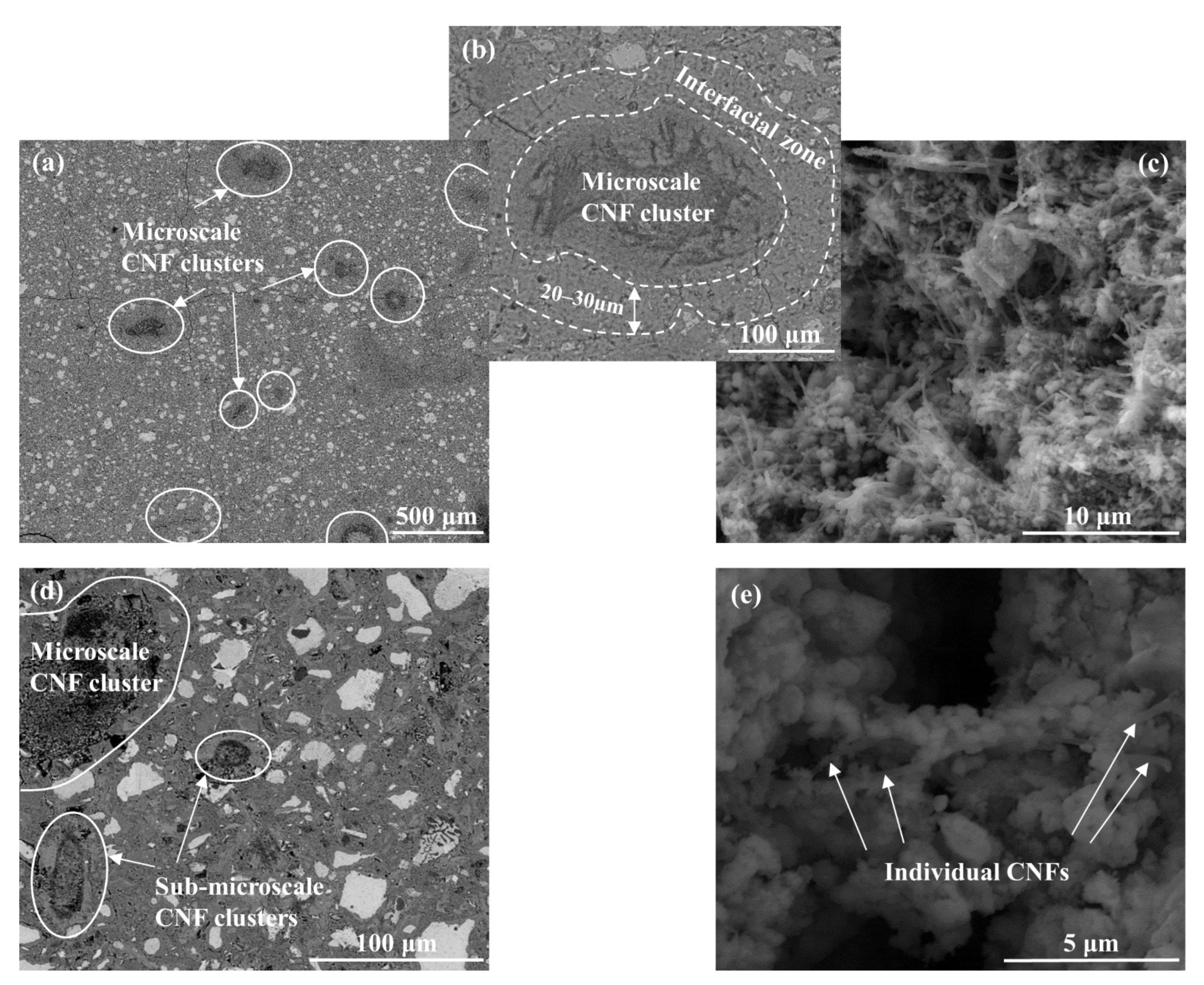
3.1. CNF Clusters and Cluster Interfacial Zone

Both individually dispersed and clustered CNFs were seen throughout the hydrated cement paste. The individually dispersed CNFs were well embedded in cement hydrates and in close proximity to only a few other fibers (Figure 2e). The clustering of CNFs formed both microscale (clusters with a diameter above 100 µm that could be easily identified via optical microscopy; Figure 2a) and sub-microscale (clusters with a diameter below 100 µm that needed to be identified via SEM; Figure 2d) CNF clusters. The clusters were entangled masses of CNFs with inter-fiber pore networks (Figure 2b,c) that induced localized zones of higher porosity and were scattered throughout the cement paste cross-section [14,25]. Cement hydrates were also found scattered within the clusters (Figure 2c), and previous work by the authors identified the presence of CH plates within the clusters [25]. Approximately 40–60% (Assumes a CNF density of 0.032 g/cm3 per the manufacturer’ specifications [87], cluster shapes that range from spherical to ellipsoidal, and a characteristic length of 0.27 mm (based on the average Feret diameter of the microscale clusters) in order to transform from surface area to volume.) of the total CNFs added during mixing (i.e., 0.2% per mass of cement × 40 to 60%) were thought to be present as microscale clusters in the final hydrated cement paste; Figure 2a. The microscale clusters ranged in size from 125 to 1500 µm and had an average Feret diameter of 270 µm, indicating that the clusters were more concentrated towards the lower end of the size distribution. The microscale clusters had an average aspect ratio of 2.0 ± 0.96 and an average circularity of 0.69 ± 0.18, suggesting that the clusters had a more ellipsoidal shape (Figure 2b) compared to the spherical shape typically associated with air voids in cement paste. Systematic measurements of the sub-microscale CNF clusters were more difficult due to their low visibility on a polished surface and were primarily accomplished via SEM imaging. The sub-microscale CNF clusters ranged in size from just a few microns up to ca. 50 µm in diameter. A similar ellipsoidal shape was also seen for the sub-microscale clusters as well as the presence of cement hydrates inside the cluster.
Previous work by the authors [25] indicated that each CNF cluster was surrounded by an interfacial zone, which had distinctive microstructural and chemical signatures compared to the surrounding cement paste. BSE imaging revealed that this interfacial zone was characterized by a greater porosity (ca. 34% increase in porosity as measured by an SEM porosity counting technique) compared to the surrounding cement paste [25] and by the absence of unhydrated cement particles (Figure 2b). EDS mapping of the sample surface also indicated a lower calcium content and higher potassium content in the interfacial zone compared to the surrounding cement paste [25]. The interfacial zone was 20–30 µm thick, with size generally independent of the size of the CNF cluster, and served as a bridge between the cement matrix and the clusters (Figure 2b).

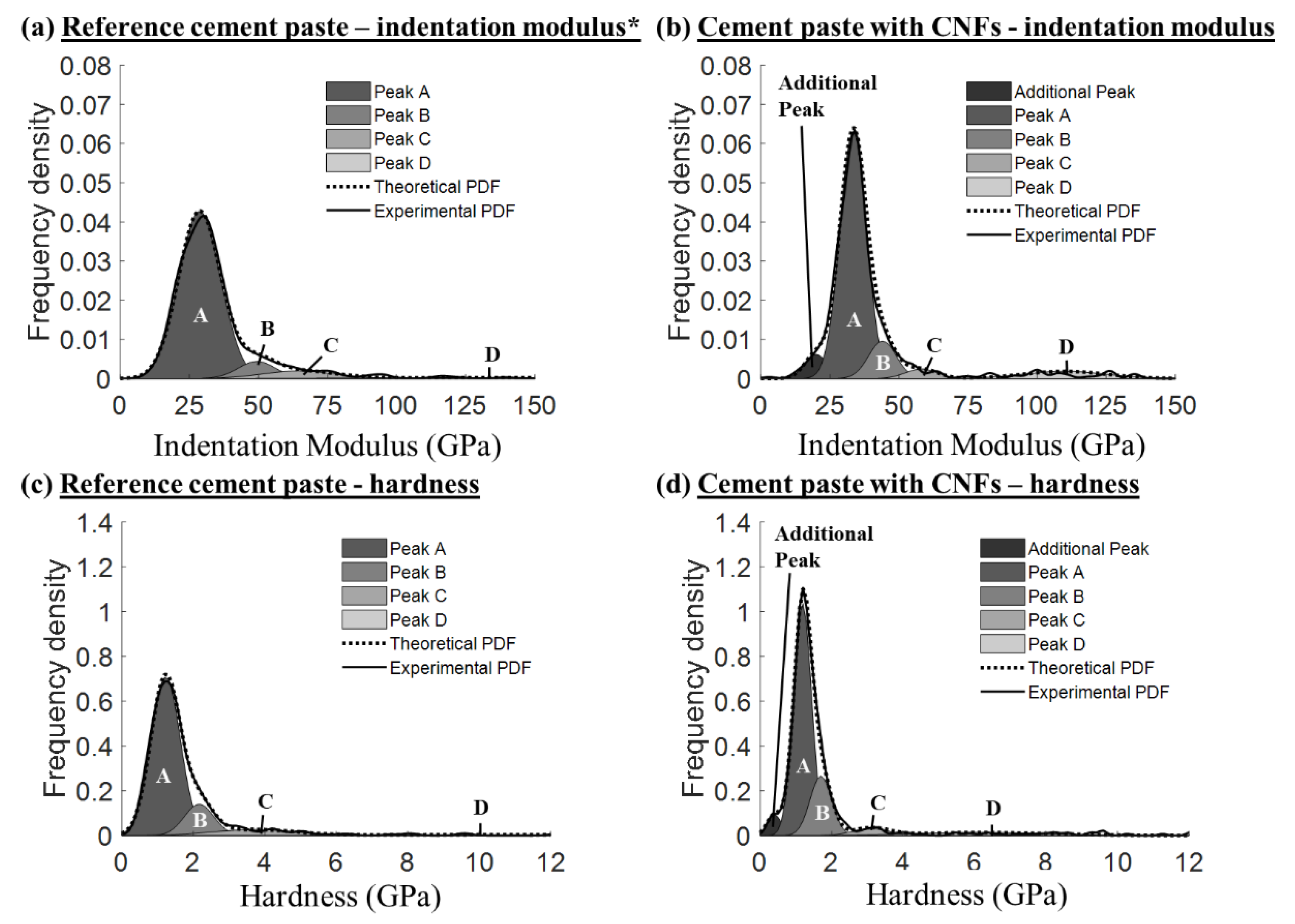
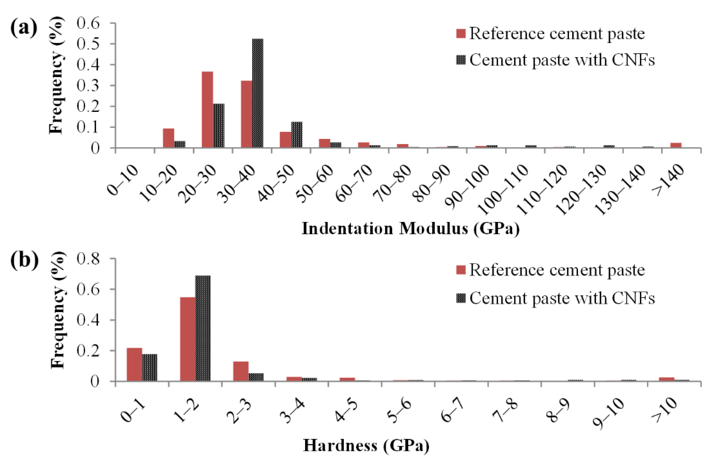
3.2. Local Indentation Modulus and Hardness

The effect of the CNFs on the cement paste micromechanical properties, as evidenced by an increase in the number of indents with indentation modulus values between 30 and 50 GPa (Figure 3a) and number of indents with hardness values in the 1 to 2 GPa range (Figure 3b), suggested that the CNFs influenced the stiffness and hardness of the primary hydrates (e.g., C–S–H phases). The combination of both well-dispersed CNFs and CNF clusters found in the composite were thought to influence the stiffness and hardness of the hydrates, primarily through a reinforcement effect at the nanoscale for the well-dispersed CNFs and a physical filling effect of the CNF clusters which led to an improved packing density and lower porosity of the surrounding bulk cement paste [25]. A similar effect has been reported with the incorporation of carbon nanotubes in cement pastes [48]. Gaussian fitting of the nanoindentation data revealed the presence of four (4) primary peaks for the reference cement paste and four (4) corresponding primary peaks for the cement paste with CNFs (Figure 4) plus an additional primary peak that was centered around low indentation modulus and hardness values (18–23 GPa and 0.2–0.7 GPa, respectively).
Normalized histograms of the raw data can be found in Figure S2, and a comparison of the theoretical and experimental CDFs can be found in Figure S3. The four primary peaks seen in both cement pastes corresponded to mechanically distinct peaks typically discussed in the literature for cement-based materials and were, for both cement pastes, labeled as Peaks A, B, C, and D (for indentation modulus values, Peak A is typically centered around 20–35 GPa, Peak B around 40–50 GPa, Peak C around 50–65 GPa, and Peak D around 100–150 GPa) [51,56,72]. The additional peak identified in the cement paste with CNFs encompassed ca. 10% of the total valid indents and was indicative of the presence of a porous assemblage of hydrated phases that exhibited an overall low stiffness. Visual examination by SEM of the location of the indents corresponding to this additional peak indicated that the majority of the indents were in or near CNF clusters or present in areas that may have included sub-micro-CNF clusters (i.e., area of higher porosity). The interfacial zone surrounding the CNF clusters was thought to have contributed to this additional peak during nanoindentation. A difference in the position of the four (4) primary peaks (Peaks A, B, C, and D) was also observed between the two cement pastes, with a statistically higher indentation modulus value for Peak A with CNF addition and an overall shift toward lower indentation modulus and hardness values for Peaks B, C, and D (Table 1; Welch’s t-test, α = 0.05). While Peak A was the predominant peak in both cement pastes, the cement paste with CNFs had a lower percentage of indents associated with Peak A (63% vs. 78%) and a higher percentage of indents associated with Peak B (16% vs. 11%), indicating a shift towards phases of higher indentation modulus values in the presence of CNFs.
In agreement with the hardness values, the average maximum displacement of the indent load–displacement curves decreased as the hardness increased from Peak A to Peak D (Figure 5). The indents associated with the cluster interfacial zones demonstrated a higher average maximum displacement (390 nm) than that of all the other indents from both cement pastes. In addition, lower average maximum displacements were seen for the indents associated with Peak A of the cement paste with CNFs compared to that of the reference cement paste (276 nm vs. 292 nm, respectively) and Peak D of the cement paste with CNFs (121 nm vs. 154 nm, respectively). In contrast, the indents associated with Peaks B and C had similar average maximum displacements for both cement pastes (234 nm vs. 225 nm and 195 nm vs. 193 nm, respectively). The higher indentation modulus value, lower percentage of indents, and lower average maximum displacement for the indents associated with Peak A for the cement paste with CNFs clearly indicated that the CNFs influenced the phases associated with this dominant Peak A.

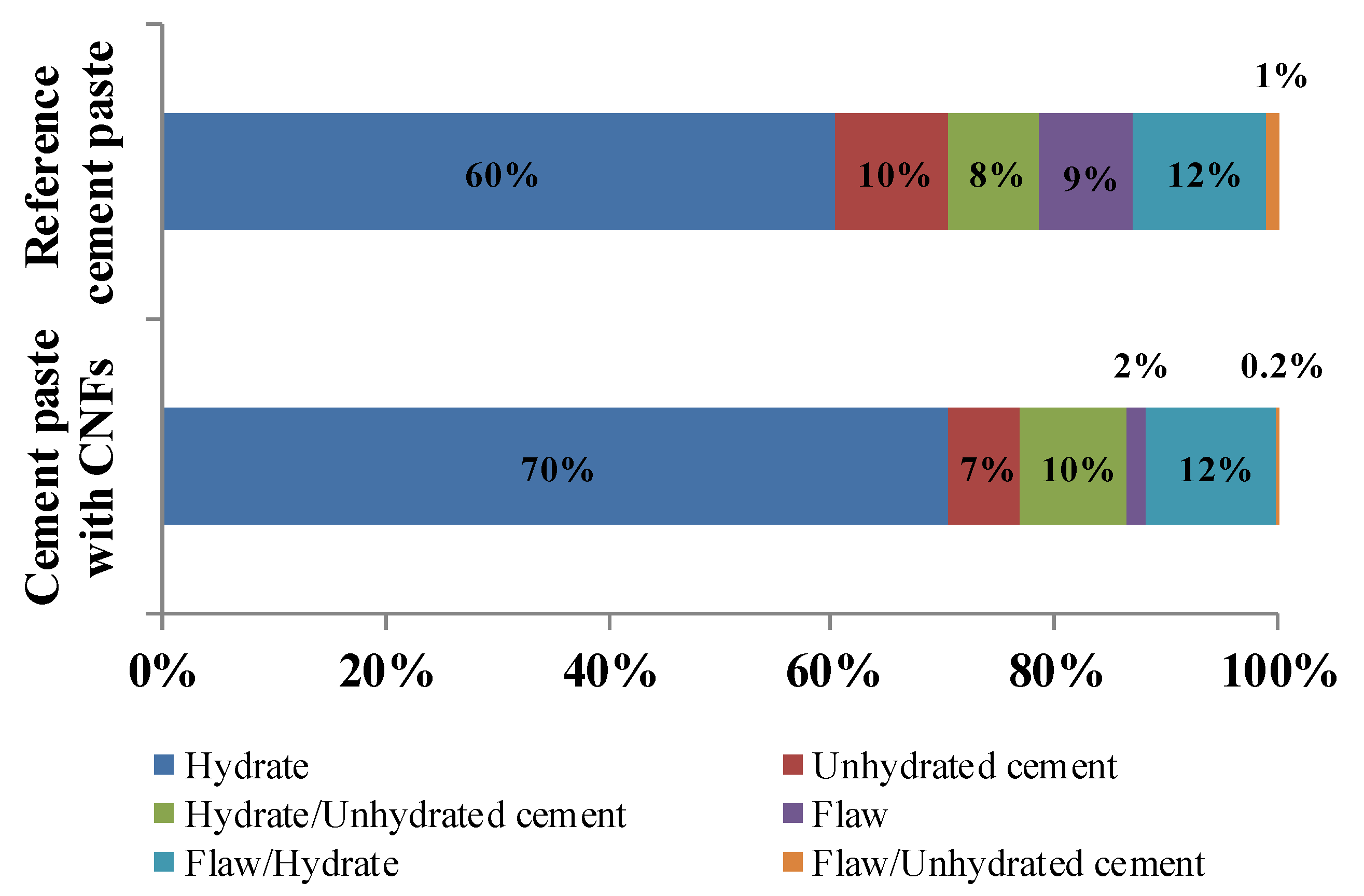
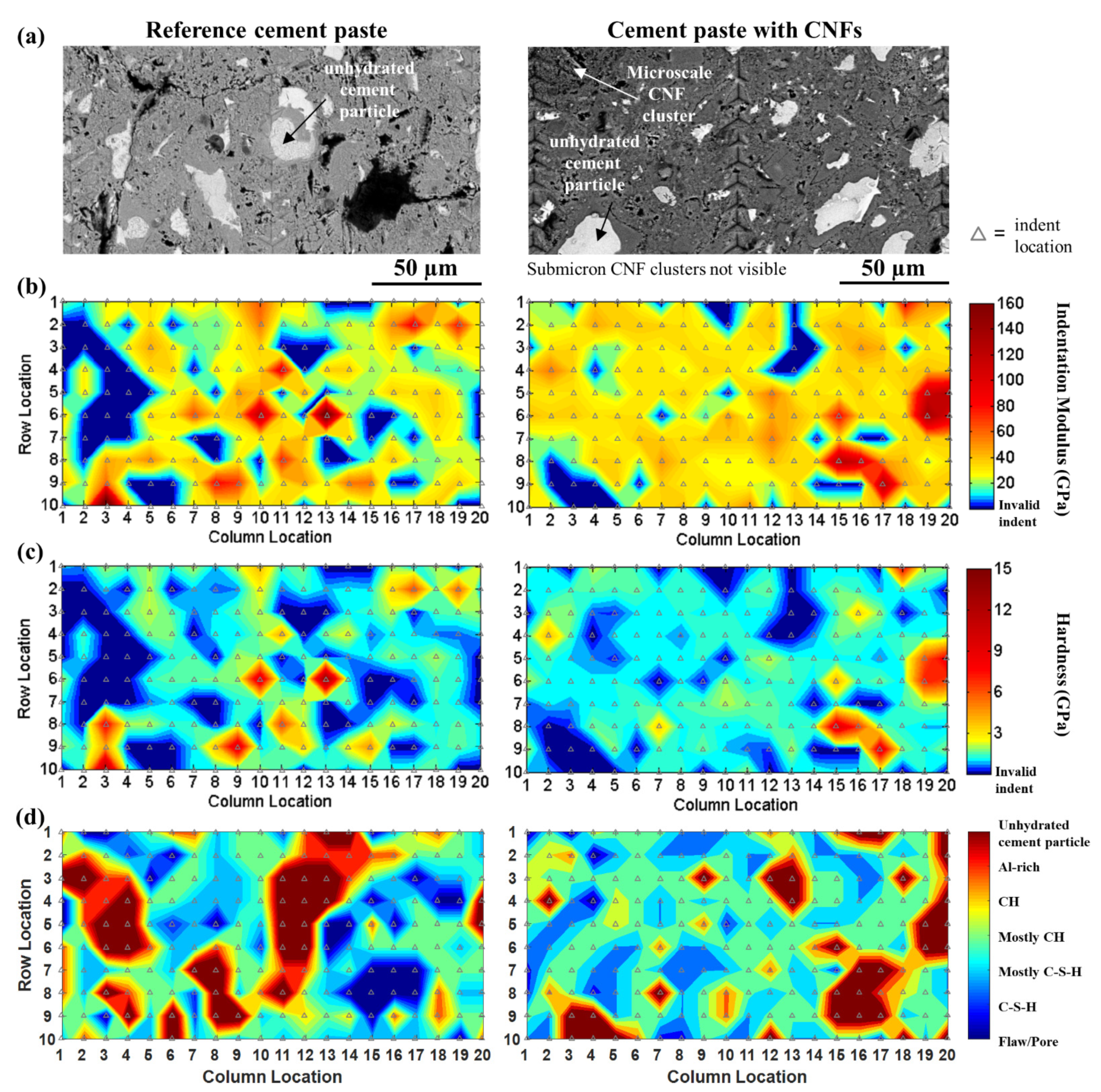
3.3. Coupled Grid Nanoindentation with SEM Analysis

Classification of the nanoindentation indents based on their visual microstructural attributes as identified using SEM (Figure 6) indicated that the cement paste with CNFs had a lower number of flaws/porosity (1.8% vs. 8.5%) compared to the reference cement paste. The difference in flaws/porosity was consistent with the overall more uniform distribution of indentation modulus and hardness seen in the contour maps of the cement paste with CNFs (Figure 7) and the results found in [25], which showed that the presence of CNFs provided for a pore refinement of the cement paste. A higher hydrate content (70.3% vs. 60.3%) with a lower unhydrated cement particle content (6.7% vs. 10.0%) was also found for the cement paste with CNFs, suggesting a higher degree of hydration in the presence of CNFs. A similar influence on the degree of hydration has been reported in the literature for carbon nanotubes (CNTs) [46,88], where the CNTs were thought to provide a filling effect in the pore network that allowed for better bonding and bridging of cement phases during hydration and may have facilitated the accelerated growth of some hydration products. Furthermore, the preferential formation of CH plates within the CNF clusters during hydration and the relative hydrophobicity of the CNF clusters was thought to influence the resulting calcium hydrate phases of the surrounding cement paste and may have helped promote the distribution of C–S–H.
The mechanically identified peaks were correlated to chemical phases based on indentation modulus and hardness measurements of cement phases reported in the literature from nanoindentation (Table 2; [52,53,56,60,61,63,64,66,71,72,80,89,90,91,92,93,94,95,96]): (i) Additional Peak—porous assemblage of main hydration products; (ii) Peak A—main hydration products; (iii) Peak B—high stiffness hydration products; (iv) Peak C—CH and unhydrated cement particles (or a combination of the two); and (v) Peak D—unhydrated cement particles. The higher mean indentation modulus value of Peak A (main hydration products, such as C–S–H) and a higher percentage of Peak B indents (thought to be CH or high stiffness C–S–H) seen in the Gaussian fitting of the indentation modulus values suggested that the CNFs influenced the formation of the main hydration products of the cement paste and played a role in the formation of higher stiffness hydration products.

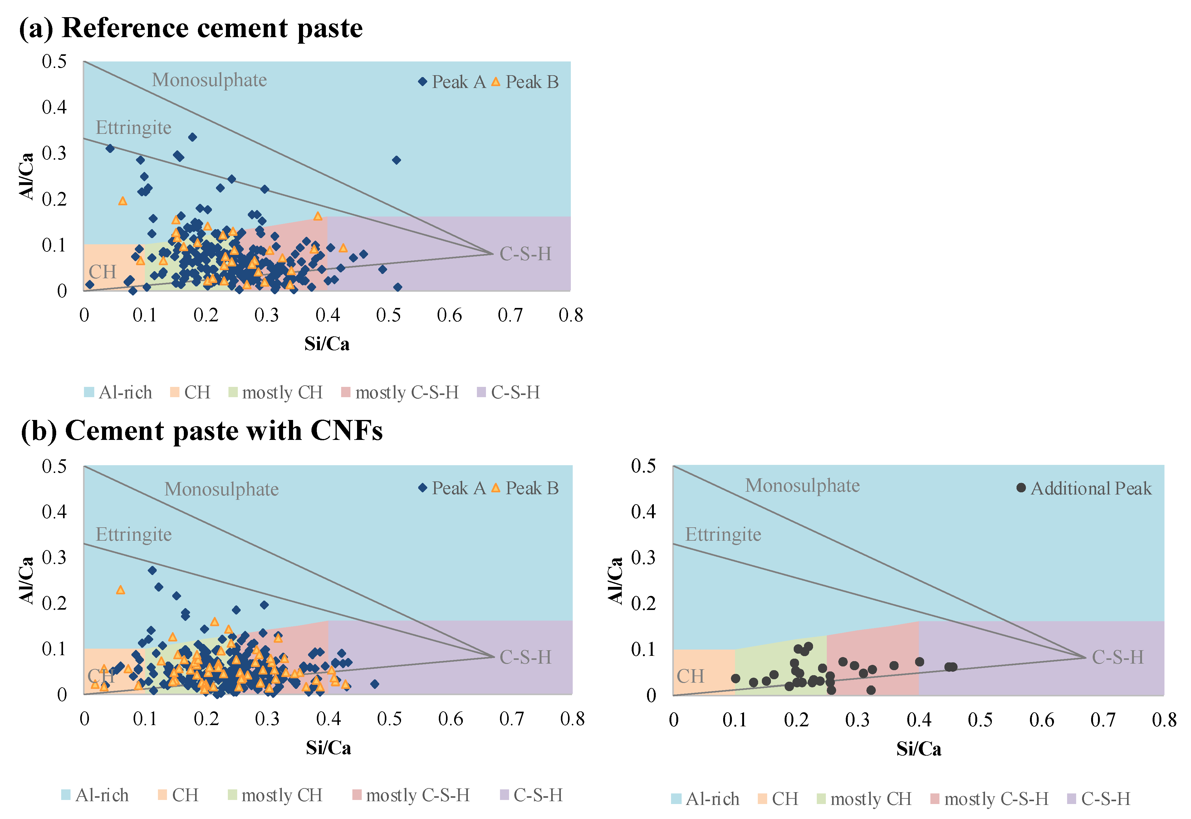
3.4. Hydrate Phase Segmentation by EDS Analysis

The chemical phase contour maps (Figure 7d) indicated a shift towards higher stiffness hydration products for the cement paste with CNFs as well as a decrease in the unhydrated cement particles. For both cement pastes, the Al-rich phases were found to be in close proximity to the unhydrated cement particles, followed by higher stiffness hydration products, such as CH, and main hydration products, such as C–S–H distributed in between. Plots of atomic ratios of aluminum to calcium (Al/Ca) versus silicon to calcium (Si/Ca) obtained from EDS analysis of the indents identified as hydrates showed that the majority of the hydrates of both cement pastes (ca. 77%) corresponding to mechanically distinct Peaks A and B were distributed along the CH/C–S–H line and represented a mixture of CH and C–S–H phases that were associated predominantly with Si/Ca ratios ranging from 0.1 to 0.4 (Figure 8). These results indicated that indentation likely occurred on a mixture of phases rather than pure phases and reflected the highly heterogeneous nature of hydrated cement pastes. A similar result has been reported in the literature [72,81]. EDS analysis further revealed that the cluster interfacial zones associated with the Additional Peak were primarily composed of mostly CH and C–S–H phases and did not contain ettringite or monosulfate phases, unlike the bulk of the cement matrix (Figure 8). This lack of Al-rich phases was consistent with the lack of unhydrated cement particles in the interfacial zone of the CNF clusters and the preferential proximity of the Al-rich phases to the unhydrated cement particles in the bulk cement matrix as seen from the spatial chemical phase contour maps (Figure 7d). The composition of the cluster interfacial zones was similar to that typically found at interfacial transition zones between cement paste and aggregates and was consistent with the Le Chatelier hydration process which favored the preferential formation of CH and C–S–H in and around the CNF clusters [102,103].
Statistical deconvolution of the PDF Gaussian fit of the indentation modulus data for the indents corresponding to the hydrates that were within the 0 to 50 GPa range and demonstrated an EDS chemical signature that was indicative of a C–S–H phase indicated the presence of three (3) phases for the reference cement paste and four (4) phases for the cement paste with CNFs (Figure 9, comparison of the empirical and theoretical CDF can be seen in Figure S4). The cluster interfacial zones identified in the cement paste with CNFs (porous assemblages of CH and C–S–H phases) were not considered in this analysis. Based on indentation modulus values provided in the literature for the 0 to 50 GPa range typically associated with C–S–H phases, Phase 1 of the reference cement paste likely corresponded to low stiffness C–S–H (indentation modulus values below 30 GPa) [52,53,60,71,91,92,98], Phase 2 to high stiffness C–S–H (indentation modulus values between 30 and 35 GPa) [52,53,60,71,91,92,98], and Phase 3 to ultra-high stiffness C–S–H (indentation modulus values above 40 GPa) [104] (Table 3). The PDF deconvolution showed that the high stiffness C–S–H dominated over the low stiffness C–S–H in the nanomechanical response of the reference cement paste, while the ultra-high stiffness C–S–H represented only a minor volume proportion. These results were consistent with the literature, which showed that for cement pastes with low w/c ratios (<0.35), a higher ratio of high-density C–S–H vs. low-density C–S–H was expected [104,105,106,107]. For the cement paste with CNFs, a statistically higher indentation modulus value for Phase 1 than that of the reference cement paste was observed, indicating a shift of the indentation modulus of the low stiffness C–S–H phase with the addition of the CNFs towards the high end of the range of values typically found in the literature for low stiffness C–S–H [52,53,60,71,91,92,98]. In addition, the volume proportion of the low stiffness C–S–H phase decreased in favor of the higher stiffness C–S–H phases (Table 3). A similar result has been reported in the literature for CNFs [108] as well as the addition of CNTs, where the CNTs were reported to increase the formation of high-density C–S–H over that of low-density C–S–H [48,95,96]. This shift in the C–S–H phase distribution and properties occurring for the cement paste with CNFs was thought to be due to the relative hydrophobicity of the CNF clusters, providing for better hydration external to the clusters, and a filling effect of the clusters that favored a higher packing density of the surrounding cement matrix. Well-dispersed CNFs were also thought to play a role in the shift towards higher stiffness C–S–H by providing a reinforcing effect in the nanoporosity of the phase. A similar effect on C–S–H has been reported in the literature for both CNFs [108] and CNTs [48]. An intermediate phase of statistically significant volume proportion was furthermore identified between the high stiffness and ultra-high stiffness C–S–H phases in the cement paste with CNFs. This phase was thought to correspond to a mixture of CH and C–S–H phases that yielded indentation modulus values that exceeded high stiffness C–S–H. The evidence of C–S–H/CH nanocomposites has been previously reported in the literature [72]. It was also thought that the shift towards higher stiffness C–S–H phases with the addition of CNFs was influenced by the preferential formation of CH within the CNF clusters (reported in [25]), possibly at the expense of the lower stiffness C–S–H.

3.5. Estimation of the Elastic Modulus of the CNF Clusters through Nanoindentation-Based Microscale–Macroscale Upscaling Approach

A nanoindentation-based microscale–macroscale upscaling method was used to estimate the elastic modulus of the CNF clusters because direct indentation on the surface of the CNF clusters was not possible as the entangled fibers did not provide a hard, flat surface that would be appropriate for nanoindentation. Yet, CNFs located near the edge of the clusters appeared to be embedded in the interfacial zone and cement hydrates (primarily CH plates) were found scattered within the CNF clusters [14,25], suggesting that the CNF clusters likely have the capacity for load transfer and to influence cracking behavior, which in turn, can impact the macroscale mechanical properties of the material. An estimate of the elastic modulus of the CNF clusters was therefore of interest to better understand the influence of the CNF clusters and interfacial zones on the macroscale properties of the composite.
The elastic modulus of the CNF clusters was determined by using a microscale–macroscale upscaling homogenization method that was informed by the local micromechanical moduli obtained from grid nanoindentation results to account for the effective, mechanical matrix phases and by the macroscale measurement of the elastic modulus obtained by pulse velocity. The mechanically identified Peak A (main hydrates) was considered the reference matrix phase for the Mori–Tanaka portion of the upscaling method, while the mechanically identified peaks B through D, the cluster interfacial zone, porosity, and the cluster phase were considered inclusion phases. The only independent/unknown variable of the microscale–macroscale upscaling homogenization method was the modulus of the “cluster phase”, which due to the nature of the model equations, was solved by using a standard, implicit, iterative procedure. All of the other parameters of the model were either characterized experimentally or were calculated based on experimental data.
Measurement of the pulse velocity of the cement paste with CNFs provided an experimental dynamic elastic modulus of 29.5 GPa. The volume fraction of the cluster phase was estimated to be 5% based on an analysis of CNF cluster surface area coverage (Assumes a cluster volume based on the measured Feret diameter of each cluster and cluster shapes that range from spherical to ellipsoidal; a characteristic length of 0.27 mm (based on the average Feret diameter of the clusters) was used to transform from surface area to volume. The size of the microscale clusters controlled the volume fraction of the cluster phase.) and Poisson’s ratio of the clusters was varied from 0.1 to 0.4 to cover the range exhibited by most materials and account for the fact that the CNF clusters were complex and random networks of entangled, flexible fibers and high porosity that deform differently depending on their packing density. The determination of the elastic modulus of the cluster phase was not sensitive to Poisson’s ratio and revealed elastic modulus values that ranged from 18 to 21 GPa (Table 4). The elastic modulus of the cluster phase was determined to be similar in magnitude to that of the cluster interfacial zone and had a non-negligible contribution to the homogenized elastic modulus (31.7 GPa without including the elastic modulus of the cluster phase vs. 29.5 GPa with the cluster phase). While the elastic modulus value of the CNF clusters is based on an estimate of the volume fraction of the CNF clusters, including the cluster phase provided evidence that the CNF clusters themselves imparted nanoscale reinforcement to the cement paste.
The CNF clusters and cluster interfacial zones exhibited the lowest stiffness of all the primary matrix phases, and the clusters acted as small, compliant inclusions relative to the matrix. This result was consistent with the improvement in the flexural toughness reported in the presence of CNF clusters by the authors [13,25]. The edges of the CNF clusters were thought to have embedded fibers that provided nanoscale reinforcement at the interfacial region and influenced the overall cluster mechanical behavior. The role of compliant inclusions relative to the matrix in matrix toughening mechanisms has been described in the literature [109,110,111]. The elastic moduli of the main hydration products (C–S–H phases, Phase A), cluster phase, and cluster interfacial zone controlled the macroscale elastic modulus of the cement paste with CNFs, indicating that the CNFs and CNF clusters played a significant role in the macroscopic response of the material and in improving flexural toughness.

4. Conclusions

The micromechanical properties of cement pastes with and without CNFs were studied using grid nanoindentation and correlated with microstructural observations and chemical analysis at each indentation site. The addition of CNFs clearly influenced the micromechanical properties of the cement paste. The presence of CNF clusters throughout the cement paste impacted the number of mechanically distinct peaks identified from statistical Gaussian fitting with the presence of a low stiffness, porous assemblage of phases that were not found in the reference cement paste and was attributed primarily to the interfacial zone surrounding the CNF clusters. The results furthermore revealed that the addition of CNFs favored higher stiffness C–S–H phases (indentation modulus of greater than 40 GPa) at the expense of the lower stiffness C–S–H (indentation modulus less than 30 GPa) and led to indentation modulus values for C–S–H that exceeded that of the high stiffness C–S–H. The indentation modulus of the cluster interfacial zone (a porous assemblage of CH and C–S–H phases), measured by nanoindentation, was in the range from 15 to 25 GPa, and the elastic modulus of the CNF clusters, estimated from the microscale–macroscale analytical homogenization method, ranged from 18 to 21 GPa. It was found that the CNF clusters acted as compliant inclusions relative to the matrix and that the CNF clusters and interfacial zone surrounding the clusters affected the macroscale elastic modulus of the cement paste. The nanoindentation-based microscale–macroscale upscaling methodology presented in this paper provided promising results to study the influence of randomly distributed inclusions at various length scales on the overall macroscale response of the composite.

Supplementary Materials

The following are available online at https://www.mdpi.com/article/10.3390/nano12020223/s1, Figure S1: (a) A representative load–displacement curve, (b) load–displacement curve that exhibits stiffening, and (c) load–displacement curve that exhibits jumps in displacement due to indenting on the entangled mass of CNFs within a cluster or improper tip contact at the boundary between two phases that present a large contrast in their mechanical behavior, Figure S2: Histogram of the normalized raw data for the (a,b) indentation modulus and (c,d) hardness of the reference cement paste and cement paste with CNFs, respectively, Figure S3: Comparison of the empirical cumulative density function (CDF) and theoretical CDF for the (a,b) indentation modulus and (c,d) hardness of the reference cement paste and cement paste with CNFs, respectively, Figure S4: Comparison of the empirical cumulative density function (CDF) and theoretical CDF for the 0 to 50 GPa range of the indentation modulus typically associated with C–S–H phases for the (a) reference cement paste and (b) cement paste with CNFs.

Author Contributions

Conceptualization, L.B. and F.S.; methodology, L.B., C.S.S., P.G.A. and F.S.; formal analysis, L.B.; investigation, L.B.; resources, P.G.A. and F.S.; data curation, L.B.; writing—original draft preparation, L.B. and F.S.; writing—review and editing, L.B., C.S.S., P.G.A. and F.S.; visualization, L.B. and F.S.; supervision, F.S.; project administration, F.S.; funding acquisition, F.S. All authors have read and agreed to the published version of the manuscript.

Funding

This research was funded by the National Science Foundation under NSF CAREER CMMI 0547024 and NSF GRFP DGE-0946822. Usage of the ESEM was provided by the U.S. Department of Energy funded Consortium for Risk Evaluation with Stakeholder Participation III (CRESP, Cooperative Agreement Number DE-FC01-06EW07053). The opinions, findings, conclusions, or recommendations expressed herein are those of the authors and do not necessarily represent the views of the Department of Energy or Vanderbilt University.

Institutional Review Board Statement

Not Applicable.

Informed Consent Statement

Not Applicable.

Data Availability Statement

The data presented in this study are available on request from the corresponding author.

Conflicts of Interest

The authors declare no conflict of interest. The funders had no role in the design of the study; in the collection, analyses, or interpretation of data; in the writing of the manuscript, or in the decision to publish the results.

References

  1. Makar, J.M.; Beaudoin, J.J. Carbon nanotubes and their applications in the construction industry. In Proceedings of the First International Symposium on Nanotechnology in Construction, Paisley, Scotland, 23–25 June 2003; pp. 331–341. [Google Scholar]
  2. Lawrence, J.G.; Berhan, L.M.; Nadarajah, A. Elastic Properties and Morphology of Individual Carbon Nanofibers. ACS Nano 2008, 2, 1230–1236. [Google Scholar] [CrossRef]
  3. Parveen, S.; Rana, S.; Fangueiro, R. A Review on Nanomaterial Dispersion, Microstructure, and Mechanical Properties of Carbon Nanotube and Nanofiber Reinforced Cementitious Composites. J. Nanomater. 2013, 2013, 19. [Google Scholar] [CrossRef]
  4. Gao, D.; Sturm, M.; Mo, Y.L. Electrical resistance of carbon-nanofiber concrete. Smart Mater. Struct. 2009, 18, 095039. [Google Scholar] [CrossRef]
  5. Gao, L.; Chou, T.-W.; Thostenson, E.T.; Zhang, Z. A comparative study of damage sensing in fiber composites using uniformly and non-uniformly dispersed carbon nanotubes. Carbon 2010, 48, 3788–3794. [Google Scholar] [CrossRef]
  6. Konsta-Gdoutos, M.S.; Aza, C.A. Self sensing carbon nanotube (CNT) and nanofiber (CNF) cementitious composites for real time damage assessment in smart structures. Cem. Concr. Compos. 2014, 53, 162–169. [Google Scholar] [CrossRef]
  7. Wang, B.; Guo, Z.; Han, Y.; Zhang, T. Electromagnetic wave absorbing properties of multi-walled carbon nanotube/cement composites. Constr. Build. Mater. 2013, 46, 98–103. [Google Scholar] [CrossRef]
  8. Wang, H.; Gao, X.; Wang, R. The influence of rheological parameters of cement paste on the dispersion of carbon nanofibers and self-sensing performance. Constr. Build. Mater. 2017, 134, 673–683. [Google Scholar] [CrossRef]
  9. Wang, H.; Shen, J.; Liu, J.; Lu, S.; He, G. Influence of carbon nanofiber content and sodium chloride solution on the stability of resistance and the following self-sensing performance of carbon nanofiber cement paste. Case Stud. Constr. Mater. 2019, 11, e00247. [Google Scholar] [CrossRef]
  10. Fu, X.; Chung, D.D.L. Submicron carbon filament cement-matrix composites for electromagnetic interference shielding. Cem. Concr. Res. 1996, 26, 1467–1472. [Google Scholar] [CrossRef]
  11. Wang, H.; Gao, X.; Liu, J.; Ren, M.; Lu, A. Multi-functional properties of carbon nanofiber reinforced reactive powder concrete. Constr. Build. Mater. 2018, 187, 699–707. [Google Scholar] [CrossRef]
  12. Liu, Y.; Wang, M.; Tian, W.; Qi, B.; Lei, Z.; Wang, W. Ohmic heating curing of carbon fiber/carbon nanofiber synergistically strengthening cement-based composites as repair/reinforcement materials used in ultra-low temperature environment. Compos. Part A Appl. Sci. Manuf. 2019, 125, 105570. [Google Scholar] [CrossRef]
  13. Stephens, C.; Brown, L.; Sanchez, F. Quantification of the re-agglomeration of carbon nanofiber aqueous dispersion in cement pastes and effect on the early age flexural response. Carbon 2016, 107, 482–500. [Google Scholar] [CrossRef] [Green Version]
  14. Brown, L.; Sanchez, F. Influence of carbon nanofiber clustering in cement pastes exposed to sulfate attack. Constr. Build. Mater. 2018, 166, 181–187. [Google Scholar] [CrossRef]
  15. Yazdanbakhsh, A.; Grasley, Z.; Tyson, B.; Abu Al-Rub, R. Distribution of Carbon Nanofibers and Nanotubes in Cementitious Composites. Transp. Res. Rec. J. Transp. Res. Board 2010, 2142, 89–95. [Google Scholar] [CrossRef] [Green Version]
  16. Hogancamp, J.; Grasley, Z. The use of microfine cement to enhance the efficacy of carbon nanofibers with respect to drying shrinkage crack resistance of portland cement mortars. Cem. Concr. Compos. 2017, 83, 405–414. [Google Scholar] [CrossRef]
  17. Barbhuiya, S.; Chow, P. Nanoscaled Mechanical Properties of Cement Composites Reinforced with Carbon Nanofibers. Materials 2017, 10, 662. [Google Scholar] [CrossRef] [PubMed] [Green Version]
  18. Makar, J. The Effect of SWCNT and Other Nanomaterials on Cement Hydration and Reinforcement. In Nanotechnology in Civil Infrastructure: A Paradigm Shift; Gopalakrishnan, K., Birgisson, B., Taylor, P., Attoh-Okine, N.O., Eds.; Springer: Berlin/Heidelberg, Germany, 2011; pp. 103–130. [Google Scholar]
  19. Mendoza, O.; Sierra, G.; Tobón, J.I. Influence of super plasticizer and Ca(OH)2 on the stability of functionalized multi-walled carbon nanotubes dispersions for cement composites applications. Constr. Build. Mater. 2013, 47, 771–778. [Google Scholar] [CrossRef]
  20. Collins, F.; Lambert, J.; Duan, W.H. The influences of admixtures on the dispersion, workability, and strength of carbon nanotube–OPC paste mixtures. Cem. Concr. Compos. 2012, 34, 201–207. [Google Scholar] [CrossRef]
  21. Parveen, S.; Rana, S.; Fangueiro, R.; Paiva, M.C. Microstructure and mechanical properties of carbon nanotube reinforced cementitious composites developed using a novel dispersion technique. Cem. Concr. Res. 2015, 73, 215–227. [Google Scholar] [CrossRef]
  22. Siegfried, M.; Tola, C.; Claes, M.; Lomov, S.V.; Verpoest, I.; Gorbatikh, L. Impact and residual after impact properties of carbon fiber/epoxy composites modified with carbon nanotubes. Compos. Struct. 2014, 111, 488–496. [Google Scholar] [CrossRef]
  23. Gao, L.; Chou, T.-W.; Thostenson, E.T.; Godara, A.; Zhang, Z.; Mezzo, L. Highly conductive polymer composites based on controlled agglomeration of carbon nanotubes. Carbon 2010, 48, 2649–2651. [Google Scholar] [CrossRef]
  24. Gao, L.; Chou, T.-W.; Thostenson, E.T.; Zhang, Z.; Coulaud, M. In situ sensing of impact damage in epoxy/glass fiber composites using percolating carbon nanotube networks. Carbon 2011, 49, 3382–3385. [Google Scholar] [CrossRef]
  25. Brown, L.; Sanchez, F. Influence of carbon nanofiber clustering on the chemo-mechanical behavior of cement pastes. Cem. Concr. Compos. 2016, 65, 101–109. [Google Scholar] [CrossRef] [Green Version]
  26. Tyson, B.; Abu Al-Rub, R.; Yazdanbakhsh, A.; Grasley, Z. Carbon Nanotubes and Carbon Nanofibers for Enhancing the Mechanical Properties of Nanocomposite Cementitious Materials. J. Mater. Civ. Eng. 2011, 23, 1028–1035. [Google Scholar] [CrossRef]
  27. Metaxa, Z.S.; Konsta-Gdoutos, M.S.; Shah, S.P. Carbon Nanofiber–Reinforced Cement-Based Materials. Transp. Res. Rec. 2010, 2142, 114–118. [Google Scholar] [CrossRef]
  28. Habermehl-Cwirzen, K.; Penttala, V.; Cwirzen, A. Surface Decoration of Carbon Nanotubes and Mechanical Properties of Cement/Carbon Nanotube Composites. Adv. Cem. Res. 2008, 20, 65–73. [Google Scholar] [CrossRef]
  29. Li, G.Y.; Wang, P.M.; Zhao, X. Mechanical behavior and microstructure of cement composites incorporating surface-treated multi-walled carbon nanotubes. Carbon 2005, 43, 1239–1245. [Google Scholar] [CrossRef]
  30. Stynoski, P.; Mondal, P.; Marsh, C. Effects of silica additives on fracture properties of carbon nanotube and carbon fiber reinforced Portland cement mortar. Cem. Concr. Compos. 2015, 55, 232–240. [Google Scholar] [CrossRef]
  31. Yu, X.; Kwon, E. A carbon nanotube/cement composite with piezoresistive properties. Smart Mater. Struct. 2009, 18, 055010. [Google Scholar] [CrossRef]
  32. Musso, S.; Tulliani, J.-M.; Ferro, G.; Tagliaferro, A. Influence of carbon nanotubes structure on the mechanical behavior of cement composites. Compos. Sci. Technol. 2009, 69, 1985–1990. [Google Scholar] [CrossRef]
  33. Chaipanich, A.; Nochaiya, T.; Wongkeo, W.; Torkittikul, P. Compressive strength and microstructure of carbon nanotubes–fly ash cement composites. Mater. Sci. Eng. A 2010, 527, 1063–1067. [Google Scholar] [CrossRef]
  34. Duan, Z.; Luo, J. Effect of multi-walled carbon nanotubes on the vibration-reduction behavior of cement. In Proceedings of the International Conference on Smart Materials and Nanotechnology in Engineering; SPIE: Bellingham, WA, USA, 2007; Volume 6423. [Google Scholar]
  35. Vera-Agullo, J.; Chozas-Ligero, V.; Portillo-Rico, D.; García-Casas, M.J.; Gutiérrez-Martínez, A.; Mieres-Royo, J.M.; Grávalos-Moreno, J. Mortar and Concrete Reinforced with Nanomaterials. In Nanotechnology in Construction 3; Springer: Berlin/Heidelberg, Germany, 2009; pp. 383–388. [Google Scholar]
  36. Hu, Y.; Luo, D.; Li, P.; Li, Q.; Sun, G. Fracture toughness enhancement of cement paste with multi-walled carbon nanotubes. Constr. Build. Mater. 2014, 70, 332–338. [Google Scholar] [CrossRef]
  37. Morsy, M.S.; Alsayed, S.H.; Aqel, M. Hybrid effect of carbon nanotube and nano-clay on physico-mechanical properties of cement mortar. Constr. Build. Mater. 2011, 25, 145–149. [Google Scholar] [CrossRef]
  38. Nam, I.W.; Kim, H.K.; Lee, H.K. Influence of silica fume additions on electromagnetic interference shielding effectiveness of multi-walled carbon nanotube/cement composites. Constr. Build. Mater. 2012, 30, 480–487. [Google Scholar] [CrossRef]
  39. Kim, H.K.; Nam, I.W.; Lee, H.K. Enhanced effect of carbon nanotube on mechanical and electrical properties of cement composites by incorporation of silica fume. Compos. Struct. 2014, 107, 60–69. [Google Scholar] [CrossRef]
  40. Peyvandi, A.; Sbia, L.A.; Soroushian, P.; Sobolev, K. Effect of the cementitious paste density on the performance efficiency of carbon nanofiber in concrete nanocomposite. Constr. Build. Mater. 2013, 48, 265–269. [Google Scholar] [CrossRef]
  41. Kim, H.K.; Park, I.S.; Lee, H.K. Improved piezoresistive sensitivity and stability of CNT/cement mortar composites with low water–binder ratio. Compos. Struct. 2014, 116, 713–719. [Google Scholar] [CrossRef]
  42. Galao, O.; Zornoza, E.; Baeza, F.J.; Bernabeu, A.; Garcés, P. Effect of carbon nanofiber addition in the mechanical properties and durability of cementitious materials. Mater. De Construcción 2012, 62, 343–357. [Google Scholar] [CrossRef] [Green Version]
  43. Abu Al-Rub, R.K.; Ashour, A.I.; Tyson, B.M. On the aspect ratio effect of multi-walled carbon nanotube reinforcements on the mechanical properties of cementitious nanocomposites. Constr. Build. Mater. 2012, 35, 647–655. [Google Scholar] [CrossRef]
  44. Ahmed Sbia, L.; Peyvandi, A.; Soroushian, P.; Lu, J.; Balachandra, A.M. Enhancement of Ultrahigh Performance Concrete Material Properties with Carbon Nanofiber. Adv. Civ. Eng. 2014, 2014, 854729. [Google Scholar] [CrossRef]
  45. Leonavičius, D.; Pundienė, I.; Pranckevičienė, J.; Kligys, M. Selection of superplasticisers for improving the rheological and mechanical properties of cement paste with CNTs. Constr. Build. Mater. 2020, 253, 119182. [Google Scholar] [CrossRef]
  46. Kowald, T.; Trettin, R. Improvement of Cementitious Binders by Multi-Walled Carbon Nanotubes. In Nanotechnology in Construction 3; Bittnar, Z., Bartos, P.M., Němeček, J., Šmilauer, V., Zeman, J., Eds.; Springer: Berlin/Heidelberg, Germany, 2009; pp. 261–266. [Google Scholar]
  47. Šmilauer, V.; Hlaváček, P.; Padevět, P. Micromechanical Analysis of Cement Paste with Carbon Nanotubes. Acta Polytech. 2012, 52, 22–28. [Google Scholar] [CrossRef]
  48. Konsta-Gdoutos, M.S.; Metaxa, Z.S.; Shah, S.P. Multi-scale mechanical and fracture characteristics and early-age strain capacity of high performance carbon nanotube/cement nanocomposites. Cem. Concr. Compos. 2010, 32, 110–115. [Google Scholar] [CrossRef]
  49. Li, G.Y.; Wang, P.M.; Zhao, X. Pressure-sensitive properties and microstructure of carbon nanotube reinforced cement composites. Cem. Concr. Compos. 2007, 29, 377–382. [Google Scholar] [CrossRef]
  50. Sobolkina, A.; Mechtcherine, V.; Khavrus, V.; Maier, D.; Mende, M.; Ritschel, M.; Leonhardt, A. Dispersion of carbon nanotubes and its influence on the mechanical properties of the cement matrix. Cem. Concr. Compos. 2012, 34, 1104–1113. [Google Scholar] [CrossRef]
  51. da Silva, W.R.L.; Němeček, J.; Štemberk, P. Application of multiscale elastic homogenization based on nanoindentation for high performance concrete. Adv. Eng. Softw. 2013, 62–63, 109–118. [Google Scholar] [CrossRef]
  52. Sorelli, L.; Constantinides, G.; Ulm, F.-J.; Toutlemonde, F. The nano-mechanical signature of Ultra High Performance Concrete by statistical nanoindentation techniques. Cem. Concr. Res. 2008, 38, 1447–1456. [Google Scholar] [CrossRef]
  53. Constantinides, G.; Ulm, F.-J. The effect of two types of C-S-H on the elasticity of cement-based materials: Results from nanoindentation and micromechanical modeling. Cem. Concr. Res. 2004, 34, 67–80. [Google Scholar] [CrossRef]
  54. Das, S.; Yang, P.; Singh, S.S.; Mertens, J.C.E.; Xiao, X.; Chawla, N.; Neithalath, N. Effective properties of a fly ash geopolymer: Synergistic application of X-ray synchrotron tomography, nanoindentation, and homogenization models. Cem. Concr. Res. 2015, 78 Part B, 252–262. [Google Scholar] [CrossRef]
  55. Ashraf, W.; Olek, J.; Tian, N. Multiscale characterization of carbonated wollastonite paste and application of homogenization schemes to predict its effective elastic modulus. Cem. Concr. Compos. 2016, 72, 284–298. [Google Scholar] [CrossRef]
  56. da Silva, W.R.L.; Němeček, J.; Štemberk, P. Methodology for nanoindentation-assisted prediction of macroscale elastic properties of high performance cementitious composites. Cem. Concr. Compos. 2014, 45, 57–68. [Google Scholar] [CrossRef]
  57. Liu, K.; Ostadhassan, M.; Bubach, B.; Ling, K.; Tokhmechi, B.; Robert, D. Statistical grid nanoindentation analysis to estimate macro-mechanical properties of the Bakken Shale. J. Nat. Gas Sci. Eng. 2018, 53, 181–190. [Google Scholar] [CrossRef]
  58. Brown, L.; Allison, P.G.; Sanchez, F. Use of nanoindentation phase characterization and homogenization to estimate the elastic modulus of heterogeneously decalcified cement pastes. Mater. Des. 2018, 142, 308–318. [Google Scholar] [CrossRef]
  59. Gay, C.; Sanchez, F. Performance of Carbon Nanofiber-Cement Composites with a High-Range Water Reducer. Transp. Res. Rec. J. Transp. Res. Board 2010, 2142, 109–113. [Google Scholar] [CrossRef]
  60. Mondal, P.; Shah, S.P.; Marks, L. A reliable technique to determine the local mechanical properties at the nanoscale for cementitious materials. Cem. Concr. Res. 2007, 37, 1440–1444. [Google Scholar] [CrossRef]
  61. Zanjani Zadeh, V.; Bobko, C.P. Nano-mechanical properties of internally cured kenaf fiber reinforced concrete using nanoindentation. Cem. Concr. Compos. 2014, 52, 9–17. [Google Scholar] [CrossRef]
  62. Němeček, J.i. Nanoindentation Based Analysis of Heterogeneous Structural Materials. In Nanoindentation in Materials Science; Nemecek, D.J., Ed.; IntechOpen: London, UK, 2012; Available online: https://www.intechopen.com/books/nanoindentation-in-materials-science/nanoindentation-based-analysis-of-heterogeneous-structural-materials (accessed on 6 January 2022).
  63. Hu, C.; Li, Z. Micromechanical investigation of Portland cement paste. Constr. Build. Mater. 2014, 71, 44–52. [Google Scholar] [CrossRef]
  64. Němeček, J. Creep effects in nanoindentation of hydrated phases of cement pastes. Mater. Charact. 2009, 60, 1028–1034. [Google Scholar] [CrossRef]
  65. Davydov, D.; Jirásek, M.; Kopecký, L. Critical aspects of nano-indentation technique in application to hardened cement paste. Cem. Concr. Res. 2011, 41, 20–29. [Google Scholar] [CrossRef]
  66. Zanjani Zadeh, V.; Bobko, C.P. Nanoscale mechanical properties of concrete containing blast furnace slag and fly ash before and after thermal damage. Cem. Concr. Compos. 2013, 37, 215–221. [Google Scholar] [CrossRef]
  67. Hay, J. Rapid Calibration of Area Function and Frame Stiffness with Express Test; Agilent Technologies Application Note; Agilent Technologies: Santa Clara, CA, USA, 2012. [Google Scholar]
  68. Wang, X.H.; Jacobsen, S.; He, J.Y.; Zhang, Z.L.; Lee, S.F.; Lein, H.L. Application of nanoindentation testing to study of the interfacial transition zone in steel fiber reinforced mortar. Cem. Concr. Res. 2009, 39, 701–715. [Google Scholar] [CrossRef]
  69. Nežerka, V.; Němeček, J.; Slížková, Z.; Tesárek, P. Investigation of crushed brick-matrix interface in lime-based ancient mortar by microscopy and nanoindentation. Cem. Concr. Compos. 2015, 55, 122–128. [Google Scholar] [CrossRef]
  70. Xiao, J.; Li, W.; Sun, Z.; Lange, D.A.; Shah, S.P. Properties of interfacial transition zones in recycled aggregate concrete tested by nanoindentation. Cem. Concr. Compos. 2013, 37, 276–292. [Google Scholar] [CrossRef]
  71. Constantinides, G.; Ulm, F.-J. The nanogranular nature of C–S–H. J. Mech. Phys. Solids 2007, 55, 64–90. [Google Scholar] [CrossRef]
  72. Chen, J.J.; Sorelli, L.; Vandamme, M.; Ulm, F.-J.; Chanvillard, G. A Coupled Nanoindentation/SEM-EDS Study on Low Water/Cement Ratio Portland Cement Paste: Evidence for C–S–H/Ca(OH)2 Nanocomposites. J. Am. Ceram. Soc. 2010, 93, 1484–1493. [Google Scholar] [CrossRef] [Green Version]
  73. Němeček, J.; Králík, V.; Vondřejc, J. Micromechanical analysis of heterogeneous structural materials. Cem. Concr. Compos. 2013, 36, 85–92. [Google Scholar] [CrossRef]
  74. Miller, M.; Bobko, C.; Vandamme, M.; Ulm, F.-J. Surface roughness criteria for cement paste nanoindentation. Cem. Concr. Res. 2008, 38, 467–476. [Google Scholar] [CrossRef]
  75. Ashraf, W.; Olek, J.; Tian, N. Nanomechanical Characterization of the Carbonated Wollastonite System. In Nanotechnology in construction: Proceedings of NICOM5; Springer: Cham, Switzerland, 2015; pp. 71–77. [Google Scholar]
  76. Oliver, W.C.; Pharr, G.M. Measurement of hardness and elastic modulus by instrumented indentation: Advances in understanding and refinements to methodology. J. Mater. Res. 2004, 19, 3–20. [Google Scholar] [CrossRef]
  77. Constantinides, G.; Ravi Chandran, K.S.; Ulm, F.J.; Van Vliet, K.J. Grid indentation analysis of composite microstructure and mechanics: Principles and validation. Mater. Sci. Eng. A 2006, 430, 189–202. [Google Scholar] [CrossRef]
  78. Clausner, A.; Richter, F. Determination of yield stress from nano-indentation experiments. Eur. J. Mech.-A/Solids 2015, 51, 11–20. [Google Scholar] [CrossRef]
  79. Němeček, J.; Králík, V.; Šmilauer, V.; Polívka, L.; Jäger, A. Tensile strength of hydrated cement paste phases assessed by micro-bending tests and nanoindentation. Cem. Concr. Compos. 2016, 73, 164–173. [Google Scholar] [CrossRef]
  80. Hu, C.; Gao, Y.; Zhang, Y.; Li, Z. Statistical nanoindentation technique in application to hardened cement pastes: Influences of material microstructure and analysis method. Constr. Build. Mater. 2016, 113, 306–316. [Google Scholar] [CrossRef]
  81. Trtik, P.; Münch, B.; Lura, P. A critical examination of statistical nanoindentation on model materials and hardened cement pastes based on virtual experiments. Cem. Concr. Compos. 2009, 31, 705–714. [Google Scholar] [CrossRef]
  82. Vandamme, M.; Ulm, F.-J.; Fonollosa, P. Nanogranular packing of C–S–H at substochiometric conditions. Cem. Concr. Res. 2010, 40, 14–26. [Google Scholar] [CrossRef]
  83. Hershey, J.R.; Olsen, P.A. Approximating the Kullback Leibler Divergence Between Gaussian Mixture Models. In Proceedings of the 2007 IEEE International Conference on Acoustics, Speech and Signal Processing—ICASSP ′07, Honolulu, HI, USA, 15–20 April 2007; pp. IV-317–IV-320. [Google Scholar]
  84. Kullback, S. Information Theory and Statistics; Dover Publications: Mineola, NY, USA, 1997. [Google Scholar]
  85. ASTM International. ASTM C597 Standard Test Method for Pulse Velocity Through Concrete; ASTM International: West Conshohocken, PA, USA, 2009; Available online: https://www.astm.org/c0597-16.html (accessed on 6 January 2022).
  86. Mori, T.; Tanaka, K. Average stress in matrix and average elastic energy of materials with misfitting inclusions. Acta Metall. 1973, 21, 571–574. [Google Scholar] [CrossRef]
  87. Applied Sciences Inc. Pyrograph -III Carbon Nanofiber PR-19-XT-LHT. Available online: https://apsci.com/product/pr-19-xt-lht/ (accessed on 11 November 2021).
  88. Makar, J.M.; Margeson, J.C.; Luh, J. Carbon nanotube/cement composites—Early results and potential applications. In Proceedings of the 3rd International Conference on Construction Materials: Performance, Innovations and Structural Implications, Vancouver, BC, Canada, 22–24 August 2005; pp. 1–10. [Google Scholar]
  89. Velez, K.; Maximilien, S.; Damidot, D.; Fantozzi, G.; Sorrentino, F. Determination by nanoindentation of elastic modulus and hardness of pure constituents of Portland cement clinker. Cem. Concr. Res. 2001, 31, 555–561. [Google Scholar] [CrossRef]
  90. Hughes, J.J.; Trtik, P. Micro-mechanical properties of cement paste measured by depth-sensing nanoindentation: A preliminary correlation of physical properties with phase type. Mater. Charact. 2004, 53, 223–231. [Google Scholar] [CrossRef]
  91. Jennings, H.M.; Thomas, J.J.; Gevrenov, J.S.; Constantinides, G.; Ulm, F.-J. A multi-technique investigation of the nanoporosity of cement paste. Cem. Concr. Res. 2007, 37, 329–336. [Google Scholar] [CrossRef] [Green Version]
  92. Zhu, W.; Hughes, J.J.; Bicanic, N.; Pearce, C.J. Nanoindentation mapping of mechanical properties of cement paste and natural rocks. Mater. Charact. 2007, 58, 1189–1198. [Google Scholar] [CrossRef]
  93. Sebastiani, M.; Moscatelli, R.; Ridi, F.; Baglioni, P.; Carassiti, F. High-resolution high-speed nanoindentation mapping of cement pastes: Unravelling the effect of microstructure on the mechanical properties of hydrated phases. Mater. Des. 2016, 97, 372–380. [Google Scholar] [CrossRef]
  94. Venkovic, N.; Sorelli, L.; Martirena, F. Nanoindentation study of calcium silicate hydrates in concrete produced with effective microorganisms-based bioplasticizer. Cem. Concr. Compos. 2014, 49, 127–139. [Google Scholar] [CrossRef]
  95. Shah, S.P.; Konsta-Gdoutos, M.S.; Metaxa, Z.S.; Mondal, P. Nanoscale Modification of Cementitious Materials. In Nanotechnology in Construction 3; Bittnar, Z., Bartos, P.M., Němeček, J., Šmilauer, V., Zeman, J., Eds.; Springer: Berlin/Heidelberg, Germany, 2009; pp. 125–130. [Google Scholar]
  96. Konsta-Gdoutos, M.S.; Metaxa, Z.S.; Shah, S.P. Highly dispersed carbon nanotube reinforced cement based materials. Cem. Concr. Res. 2010, 40, 1052–1059. [Google Scholar] [CrossRef]
  97. Lee, H.; Vimonsatit, V.; Chindaprasirt, P.; Ngo, T.; Mendis, P. Creep properties of cement and alkali activated fly ash materials using nanoindentation technique. Constr. Build. Mater. 2018, 168, 547–555. [Google Scholar] [CrossRef] [Green Version]
  98. Acker, P. Swelling, shrinkage and creep: A mechanical approach to cement hydration. Mater. Struct. 2004, 37, 237–243. [Google Scholar] [CrossRef]
  99. Acker, P. Micromechanical analysis of creep and shrinkage mechanisms. In Creep, Shrinkage, and Durability Mechanics of Concrete and Other Quasi-Brittle Materials; Ulm, F.-J., Bažant, Z.P., Wittmann, F.H., Eds.; Elsevier: London, UK, 2001; pp. 15–25. [Google Scholar]
  100. Vandamme, M.; Ulm, F.-J. Nanogranular origin of concrete creep. Proc. Natl. Acad. Sci. USA 2009, 106, 10552–10557. [Google Scholar] [CrossRef] [Green Version]
  101. Hu, C.; Li, Z. Property investigation of individual phases in cementitious composites containing silica fume and fly ash. Cem. Concr. Compos. 2015, 57, 17–26. [Google Scholar] [CrossRef]
  102. Scrivener, K.L.; Crumbie, A.K.; Laugesen, P. The Interfacial Transition Zone (ITZ) Between Cement Paste and Aggregate in Concrete. Interface Sci. 2004, 12, 411–421. [Google Scholar] [CrossRef]
  103. Ollivier, J.P.; Maso, J.C.; Bourdette, B. Interfacial transition zone in concrete. Adv. Cem. Based Mater. 1995, 2, 30–38. [Google Scholar] [CrossRef]
  104. Ulm, F.-J.; Vandamme, M. Probing Nano-structure of C-S-H by Micro-mechanics Based Indentation Techniques. In Nanotechnology in Construction 3: Proceedings of the NICOM3; Bittnar, Z., Bartos, P.J.M., Němeček, J., Šmilauer, V., Zeman, J., Eds.; Springer: Berlin/Heidelberg, Germany, 2009; pp. 43–53. [Google Scholar]
  105. Tennis, P.D.; Jennings, H.M. A model for two types of calcium silicate hydrate in the microstructure of Portland cement pastes. Cem. Concr. Res. 2000, 30, 855–863. [Google Scholar] [CrossRef]
  106. Jennings, H.M. A model for the microstructure of calcium silicate hydrate in cement paste. Cem. Concr. Res. 2000, 30, 101–116. [Google Scholar] [CrossRef]
  107. Constantinides, G.; Ulm, F.-J.; Van Vliet, K. On the use of nanoindentation for cementitious materials. Mater. Struct. 2003, 36, 191–196. [Google Scholar] [CrossRef]
  108. Akono, A.-T. Nanostructure and Fracture Behavior of Carbon Nanofiber-Reinforced Cement Using Nanoscale Depth-Sensing Methods. Materials 2020, 13, 3837. [Google Scholar] [CrossRef] [PubMed]
  109. Jajam, K.C.; Tippur, H.V. Role of inclusion stiffness and interfacial strength on dynamic matrix crack growth: An experimental study. Int. J. Solids Struct. 2012, 49, 1127–1146. [Google Scholar] [CrossRef] [Green Version]
  110. Jajam, K.; Tippur, H. Interaction between a dynamically growing crack with stiff and compliant inclusions using DIC and high-speed photography. In Application of Imaging Techniques to Mechanics of Materials and Structures; Springer: New York, NY, USA, 2013; pp. 63–69. [Google Scholar]
  111. Wakeel, S.A. Theoretical and Experimental Investigation of Matrix Inclusions on the Fracture Toughness of Composite Material. Ph.D. Thesis, Civil, Environmental & Architectural Engineering Department, University of Colorado Boulder, Boulder, CO, USA, 2017. Available online: https://scholar.colorado.edu/concern/graduate_thesis_or_dissertations/ft848q91n (accessed on 6 January 2022).
Figure 1. Cross-section of the (a) reference cement paste and (b) cement paste with CNFs showing the location of the nanoindentation grids and (c) SEM image of a representative nanoindentation grid showing 200 indents (yellow triangles are enlarged to show indent locations).
Nanomaterials 12 00223 g001
Figure 2. SEM images showing (a) the distribution of microscale CNF clusters in cement paste, (b) an individual CNF cluster and surrounding interfacial zone, (c) the entangled mass of CNFs and cement hydrates within a cluster, (d) the distribution of sub-microscale CNF clusters in cement paste, and (e) individual CNFs that were well embedded in the cement paste.
Nanomaterials 12 00223 g002
Figure 3. Histograms of the indentation (a) modulus and (b) hardness for the reference cement paste (414 valid indents) and the cement paste with CNFs (479 valid indents).
Nanomaterials 12 00223 g003
Figure 4. Multimodal Gaussian fitting results for the indentation modulus (a,b) and hardness (c,d) of the reference cement paste and cement paste with CNFs, respectively. * Indentation modulus data of the reference cement paste have been reported in [58].
Nanomaterials 12 00223 g004
Figure 5. Load displacement curves for the mechanically distinct peaks identified in (a) the reference cement paste and (b) the cement paste with CNFs.
Nanomaterials 12 00223 g005
Figure 6. Visual microstructural classification of indents based on SEM image analysis for the reference cement paste and the cement paste with CNFs.
Nanomaterials 12 00223 g006
Figure 7. (a) SEM backscattered electron (BSE) image of a representative nanoindentation grid and corresponding (b) indentation modulus, (c) hardness, and (d) chemical phase contour maps for the reference cement paste (left) and the cement paste with CNFs (right).
Nanomaterials 12 00223 g007
Figure 8. Segmentation of hydrates by chemical composition using SEM/EDS analysis for the (a) reference cement paste and (b) cement paste with CNFs.
Nanomaterials 12 00223 g008
Figure 9. Normalized histogram of the raw data (left) and multimodal Gaussian fitting results (right) for the 0 to 50 GPa range of the indentation modulus typically associated with C–S–H phases for the (a) reference cement paste and (b) cement paste with CNFs.
Nanomaterials 12 00223 g009
Table 1. Mean values of the indentation modulus and hardness and percent of indents for each mechanically distinct peak identified for the reference cement paste and the cement paste with CNFs.
Indentation ModulusHardness
µ ± σ (GPa) 1% of Indentsµ ± σ (GPa) 1% of Indents
Reference Cement PastePeak A28.7 ± 7.6 277.51.2 ± 0.4169.1
Peak B49.5 ± 6.8 211.12.2 ± 0.4118.1
Peak C64.6 ± 13.2 26.53.7 ± 1.28.5
Peak D135.0 ± 52.0 24.810.6 ± 3.64.3
Cement Paste with CNFsAdditional Peak 20.0 ± 4.210.20.4 ± 0.26.3
Peak A33.4 ± 4.863.31.2 ± 0.354.7
Peak B44.0 ± 5.016.31.7 ± 0.328.2
Peak C58.2 ± 5.84.03.1 ± 0.54.6
Peak D110.0 ± 15.06.36.2 ± 2.06.3
1 µ = mean; σ = standard deviation. 2 Data reported in [58].
Table 2. Classification of mechanically distinct phases (Additional Peak and Peaks A–D, this study) with their corresponding chemical phases as determined from indentation modulus and hardness measurements of cement phases reported in the literature from nanoindentation.
Indentation Modulus (GPa)Hardness (GPa)References
Additional PeakPeak ACalcium silicate hydrate, C–S–H
Low stiffness16.6 ± 4.7 30.7 ± 0.1Lee et al. [97]
18.1 ± 4.0 Jennings et al. [91]
18.2 ± 4.20.5 ± 0.1Constantinides et al. [71]
19.7 ± 2.50.6 ± 0.03Sorelli et al. [52]
20.0 ± 2.00.8 ± 0.2Acker [98,99]
21.7 ± 2.2 Constantinides et al. [53]
22.9 ± 0.760.9 ± 0.1Mondal et al. [60]
23.4 ± 3.40.7 ± 0.2Zhu et al. [92]
23.7 ± 5.90.7 ± 0.2Vandamme et al. [100]
25.2 ± 2.8 10.8 ± 0.3 1Hu et al. [101]
30.1 ± 2.3 3 Sebastiani et al. [93]
High stiffness29.1 ± 4.0 Constantinides et al. [71]
Peak B29.4 ± 2.40.8 ± 0.2Constantinides et al. [53]
29.8 ± 4.0 Lee et al. [97]
31.0 ± 4.01.4 ± 0.2Jennings et al. [91]
31.0 ± 4.00.9 ± 0.3Acker [98,99]
31.2 ± 2.51.2 ± 0.1Mondal et al. [60]
31.4 ± 2.11.3 ± 0.2Zhu et al. [92]
31.6 ± 2.9 21.1 ± 0.2 2Hu et al. [101]
34.2 ± 5.01.4 ± 0.4Sorelli et al. [52]
36.1 ± 3.41.0 ± 0.2Vandamme et al. [100]
39.3 ± 2.8 4 Sebastiani et al. [93]
Ultra-high stiffness41.5 ± 1.81.4 ± 0.3Mondal et al. [60]
42.8 ± 2.31.4 ± 0.2Vandamme et al. [82]
47.2 ± 6.01.6 ± 0.3Vandamme et al. [100]
Calcium hydroxide, CH36.0 ± 3.01.4 ± 0.5Acker [98,99]
Peak C38.0 ± 5.0 Constantinides et al. [53]
40.3 ± 4.21.3 ± 0.2Constantinides et al. [71]
48.7 ± 10.52.4 ± 1.2Lee et al. [97]
Unhydrated cement particles
Alite125 ± 79.2 ± 0.5Velez et al. [89]
Peak DTetracalcium aluminoferrite, 4CaO·Al2O3·Fe2O3 (C4AF)125 ± 259.5 ± 1.4Velez et al. [89]
125 ± 259.5 ± 3.0Acker [98,99]
Belite127 ± 108.8 ± 1.0Velez et al. [89]
Dicalcium silicate, 2CaO·SiO2 (C2S)130 ± 208.0 ± 1.0Velez et al. [89]
130 ± 208.0 ± 2.0Acker [98,99]
Tricalcium silicate, 3CaO·SiO2 (C3S)135 ± 78.7 ± 0.5Velez et al. [89]
135 ± 78.7 ± 1.0Acker [98,99]
Tricalcium aluminate, 3CaO·Al2O3 (C3A)145 ± 1010.8 ± 0.7Velez et al. [89]
145 ± 1010.8 ± 1.5Acker [98,99]
1 Outer product; 2 Inner product; 3 Low density; 4 High density.
Table 3. Output from the Gaussian fitting algorithm for the 0–50 GPa indentation modulus range of the phases typically associated with C–S–H phases for the reference cement paste and cement paste with CNFs.
Reference Cement PasteCement Paste w/CNFsComparison to Literature
Indentation Modulus µ ± σ (GPa)% of indentsIndentation Modulus µ ± σ (GPa)% of indentsIndentation Modulus
(GPa)
Phase 1 122.2 ± 3.525.9%28.3 ± 2.018.9%Low stiffness C–S–H18.0–24.0 [52,60,91,92,100]
Phase 2 231.2 ± 5.265.5%34.1 ± 2.956.6%High stiffness C–S–H31.0–36.5 [52,60,91,92,100]
Phase 3 345.7 ± 3.58.6%44.3 ± 3.510.5%Ultra-high stiffness C–S–H41.0–47.5 [60,100]
Additional Phase--39.8 ± 1.814.0%Intermediate C–S–H phase (between high and ultra-high)(this paper)
1 Phase 1 likely corresponded to low stiffness C–S–H. 2 Phase 2 likely corresponded to high stiffness C–S–H. 3 Phase 3 likely corresponded to ultra-high stiffness C–S–H.
Table 4. Input parameters from grid nanoindentation data plus a phase for the CNF clusters and calculated overall homogenized elastic modulus of the cement paste with CNFs from the microscale–macroscale analytical homogenization method.
Indentation Modulus (GPa)Volume Fraction (%)Adjusted Volume Fraction (%)Poisson’s Ratio
Model ParametersCluster Phase -5.00.1–0.4
Cluster Interfacial Zone20.011.09.70.3
Phase A33.466.658.70.3
Phase B44.016.514.50.3
Phase C58.24.23.70.3
Phase D110.01.81.60.3
Porosity 1--6.8-
Estimated Model ParameterCluster Phase18.0–21.0
Macroscale Modulus Values
Homogenized Elastic Modulus (GPa)With cluster phase29.5
Without cluster phase31.7
Measured Elastic Modulus (GPa)By pulse velocity29.5 ± 0.5
1 Porosity = Corrected SEM Porosity using a correction factor of 0.6 to account for the fraction of porosity outside the SEM domain as detailed in [58].
Publisher’s Note: MDPI stays neutral with regard to jurisdictional claims in published maps and institutional affiliations.

