

Application of Triboelectric Nanogenerator in Fluid Dynamics Sensing: Past and Future


Abstract
:1. Introduction
2. Introduction of TENG
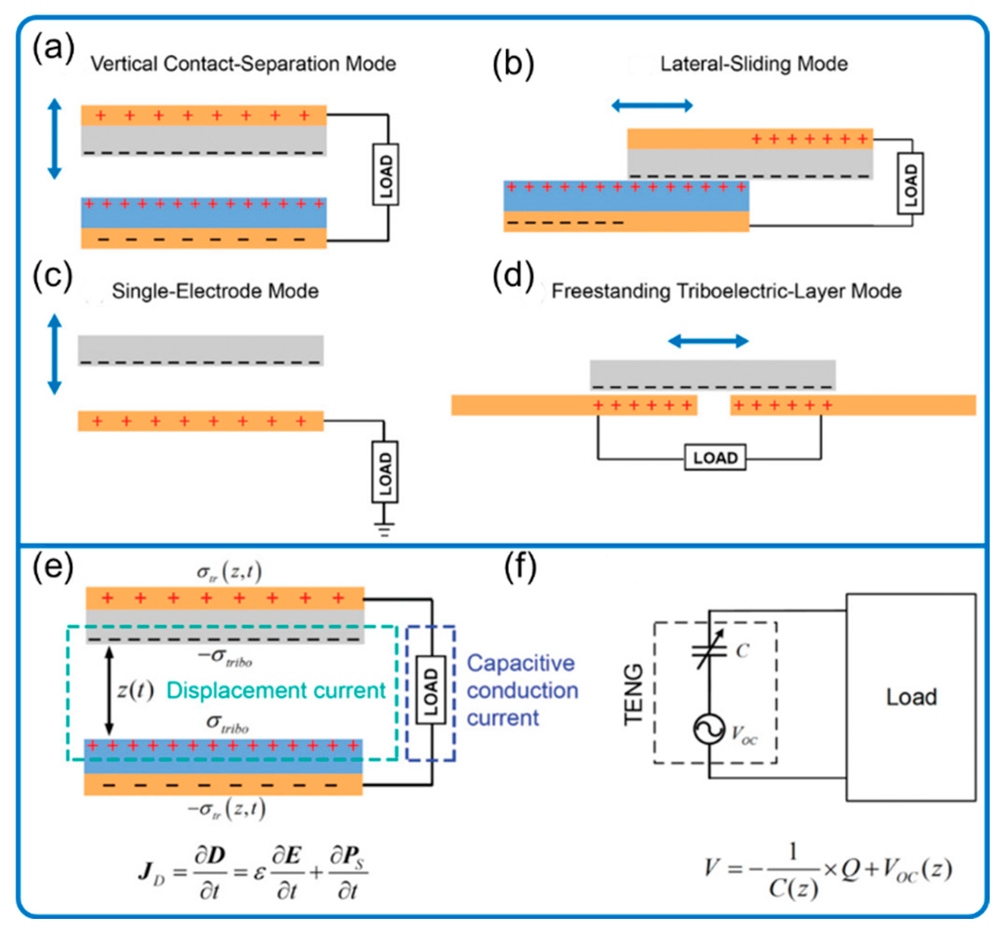
2.1. Principle of TENG
2.2. Advantages of Ordinary TENG
3. TENG for Fluid Dynamics Sensing: Past
3.1. Meteorology-Related Sensing
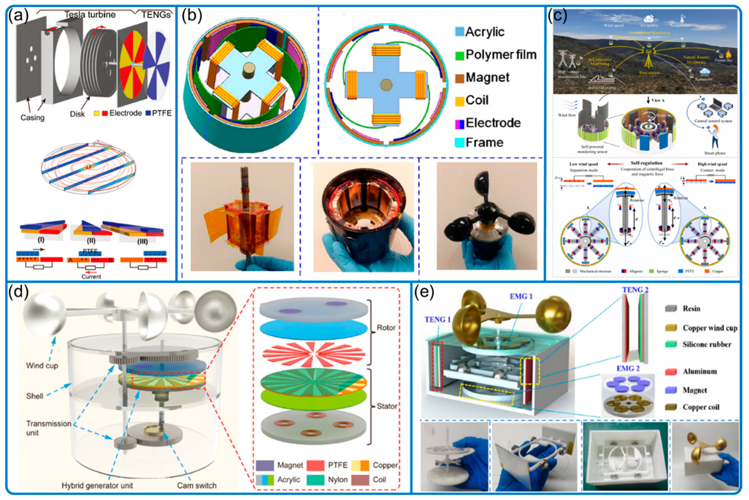
- (a)
- Wind speed and direction: conventional wind cups and turbine.


| Reference | Wind Speed (m/s) | Wind Direction | Features |
|---|---|---|---|
| Wang et al. [24] | 3.5 to 9.0 | N/A | EMG hybrid device with ultra-low friction |
| Chen et al. [22] | N/A | N/A | A freestanding bladeless-turbine-based (tesla turbine) |
| Wang et al. [18] | 2.7 to 8.0 | Yes | Freestanding (soft contact) disk-like |
| Han et al. [20] | 6.0 to 12.0 | Yes, EMG indicator | Ball bearing-like with graded electrodes |
| Fan et al. [23] | 4.0 to 15.0 | N/A | A cam structure to convert rotational to linear motion |
| Lu et al. [27] | 6.0 to 12.0 | N/A | Freestanding mode disk-like |
| Zhang et al. [19] | 3.0 to 15.0 | Yes, with only 3 signal channels | Coded electrodes for wind direction within 2 s |
| Ye et al. [28] | 1.55 to 15.0 | N/A | Combined 3 TENGs (flag, disk-brush soft contact, and EMG) |
| Zhang et al. [21] | 3.0 to 15.0 | Yes, array of devices | Contact separation mode in rotational device |
| Ma et al. [29] | 2.9 to 9.1 | N/A | Wheat-straw based TENG |
| Zou et al. [26] | 2.0 to 12.0 | N/A | Self-regulated contact-separation mode; can start with low wind speed |
| He et al. [30] | 3.77 to 11.91 | N/A | Disk-brush-like freestanding mode |
| Luo et al. [25] | 3.0 to 15.0 | N/A | Travel-controlled approach with cam switch |
- (b)
- Wind speed and direction: flutter- and flag-type
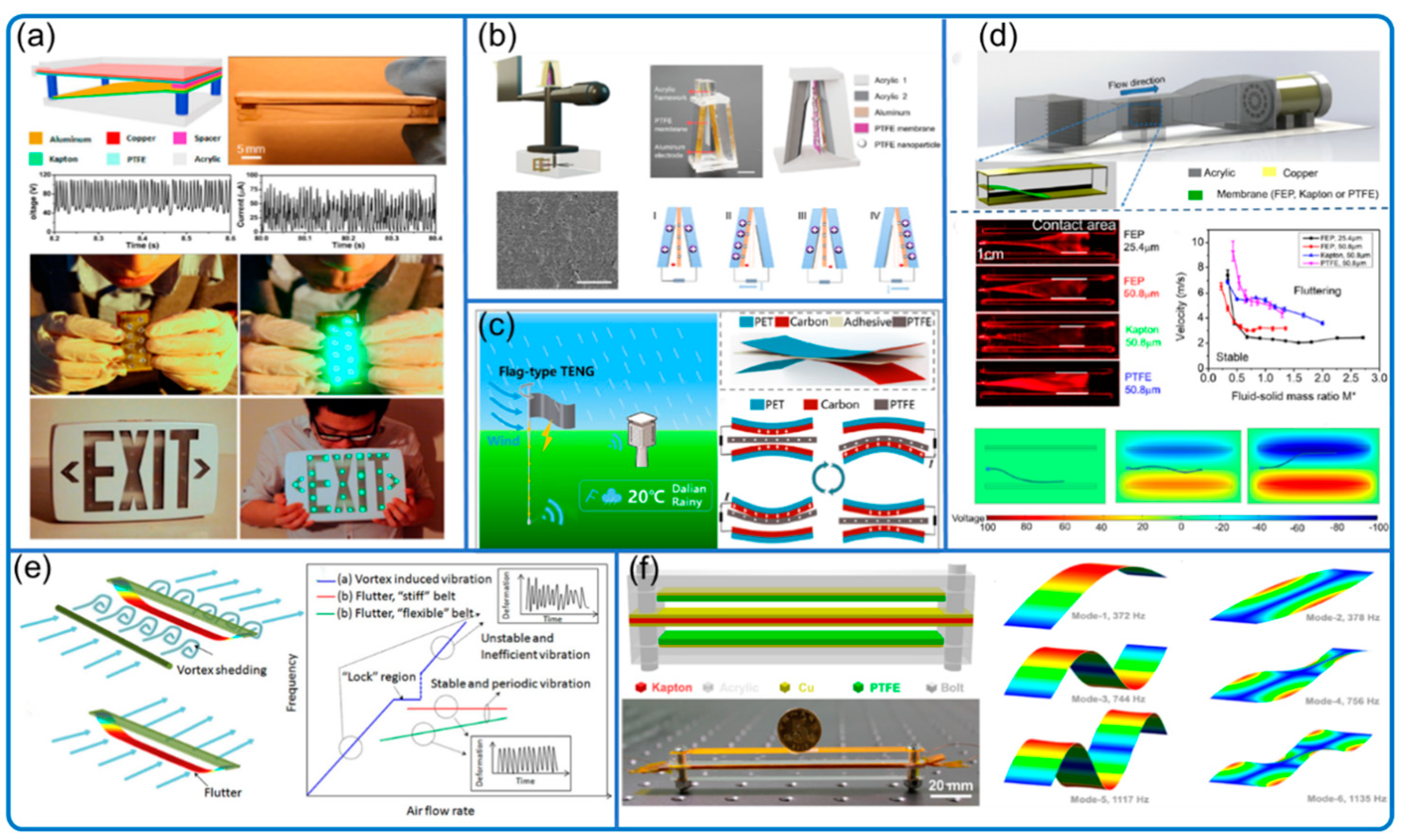
| Reference | Wind Speed (m/s) | Wind Direction | Features |
|---|---|---|---|
| Yang et al. [31] | 6.0 to 14.0 | Yes, arrayed devices | The earliest flutter-type TENG |
| Zhao et al. [48] | 3.0 to 32.0 | N/A | Flag-type device with fabricated belts |
| Ravichandran et al. [40] | 0.5 to 10 | N/A | Venturi flutter-type; the interested zone wind speed is increased due to Bernoulli principle |
| Wang et al. [44] | 2.0 to 7.5 | Yes, circuit indicator with 4 directions | Flag-type with humidity resistance |
| Wang et al. [46] | 4.0 to 11.0 | N/A | Flutter-type TENGs as wind barrier |
| Zaw et al. [50] | 1.5 to 2.7 | Yes, wind direction sensitive | Flutter-type but ripped style TENG. |
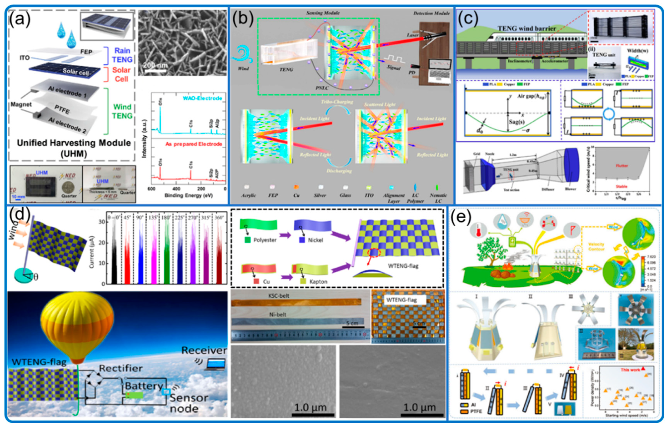
| Roh et al. [47] | 6.0 to 13.0 | N/A | Weather monitoring system with rain and wind flutter TENG with solar panel |
| Li et al. [51] | 1.6 to 14.0 | N/A | Flutter-type TENG with carbon nano thorn arrays on the electrode |
| Liu et al. [41] | 15.0 to 25.0 | N/A | Flutter-type with expanded chamber |
| Xu et al. [43] | 2.9 to 24.0 | Yes | Flutter-type; photoelectric sensor for direction and wind blow toward the long side |
| Wang et al. [49] | 2.5 to 10.0 | N/A | Flutter-type; wireless sensing with mechanical−electrical−optical signal conversion |
| Zhang et al. [45] | 1.8 to 4.3 | Yes | Flow induced vibration; 6 wind directions by array; fire detection |
- (c)
- Rain monitoring:

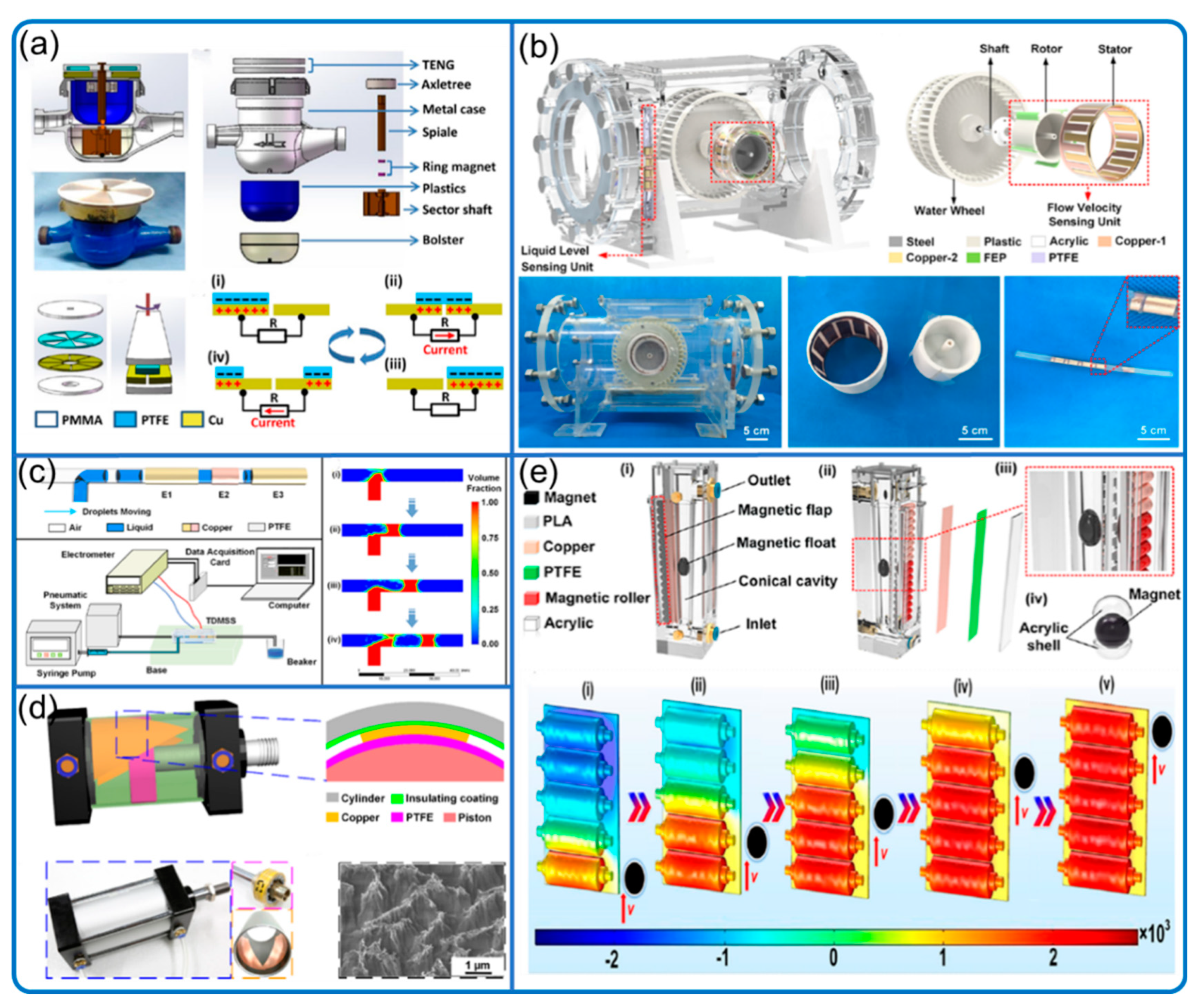
3.2. Fluid Sensing in Pipes and Tunnels
- (a)
- Waterwheel-type
- (b)
- Solid–liquid interface contact electrification
- (c)
- Cylinder-type
3.3. Remote Media Vibration and Object Sensing
3.4. Water Wave Motion

3.5. Structural Vibration Due to Moving Fluid
4. TENG for Fluid Dynamics Sensing: Future
5. Challenges and Possible Solutions
Author Contributions
Funding
Acknowledgments
Conflicts of Interest
References
- Wu, C.; Wang, A.C.; Ding, W.; Guo, H.; Wang, Z.L. Triboelectric Nanogenerator: A Foundation of the Energy for the New Era. Adv. Energy Mater. 2019, 9, 1802906. [Google Scholar] [CrossRef]
- Fan, F.R.; Tian, Z.Q.; Wang, Z.L. Flexible Triboelectric Generator. Nano Energy 2012, 1, 328–334. [Google Scholar] [CrossRef]
- Gao, Q.; Cheng, T.; Wang, Z.L. Triboelectric Mechanical Sensors—Progress and Prospects. Extrem. Mech. Lett. 2021, 42, 101100. [Google Scholar] [CrossRef]
- Wang, Z.L. On the First Principle Theory of Nanogenerators from Maxwell’s Equations. Nano Energy 2020, 68, 104272. [Google Scholar] [CrossRef]
- Wang, Z.L. Triboelectric Nanogenerators as New Energy Technology for Self-Powered Systems and as Active Mechanical and Chemical Sensors. ACS Nano 2013, 7, 9533–9557. [Google Scholar] [CrossRef]
- Zou, H.; Guo, L.; Xue, H.; Zhang, Y.; Shen, X.; Liu, X.; Wang, P.; He, X.; Dai, G.; Jiang, P.; et al. Quantifying and Understanding the Triboelectric Series of Inorganic Non-Metallic Materials. Nat. Commun. 2020, 11, 2093. [Google Scholar] [CrossRef] [PubMed]
- Wang, Z.L.; Wang, A.C. On the Origin of Contact-Electrification. Mater. Today 2019, 30, 34–51. [Google Scholar] [CrossRef]
- Wang, Z.L. On Maxwell’s Displacement Current for Energy and Sensors: The Origin of Nanogenerators. Mater. Today 2017, 20, 74–82. [Google Scholar] [CrossRef]
- Wang, Z.L.; Jiang, T.; Xu, L. Toward the Blue Energy Dream by Triboelectric Nanogenerator Networks. Nano Energy 2017, 39, 9–23. [Google Scholar] [CrossRef]
- Wang, Z.L. On the Expanded Maxwell’s Equations for Moving Charged Media System—General Theory, Mathematical Solutions and Applications in TENG. Mater. Today 2022, 52, 348–363. [Google Scholar] [CrossRef]
- Wang, H.; Wang, J.; Yao, K.; Fu, J.; Xia, X.; Zhang, R.; Li, J.; Xu, G.; Wang, L.; Yang, J.; et al. A Paradigm Shift Fully Self-Powered Long-Distance Wireless Sensing Solution Enabled by Discharge-Induced Displacement Current. Sci. Adv. 2021, 7, eabi6751. [Google Scholar] [CrossRef]
- Wang, H.; Fu, J.; Wang, J.; Su, L.; Zi, Y. Tribophotonics: An Emerging Self-Powered Wireless Solution toward Smart City. Nano Energy 2022, 97, 107196. [Google Scholar] [CrossRef]
- Wang, Z.L.; Lin, L.; Chen, J.; Niu, S.; Zi, Y. Triboelectric Nanogenerators; Green Energy and Technology; Springer International Publishing: Cham, Switzerland, 2016. [Google Scholar] [CrossRef]
- Tang, W.; Chen, B.D.; Wang, Z.L. Recent Progress in Power Generation from Water/Liquid Droplet Interaction with Solid Surfaces. Adv. Funct. Mater. 2019, 29, 1901069. [Google Scholar] [CrossRef]
- Nguyen, Q.T.; Ahn, K.K.K. Fluid-Based Triboelectric Nanogenerators: A Review of Current Status and Applications. Int. J. Precis. Eng. Manuf.—Green Technol. 2021, 8, 1043–1060. [Google Scholar] [CrossRef]
- Wang, Z.; An, J.; Nie, J.; Luo, J.; Shao, J.; Jiang, T.; Chen, B.; Tang, W.; Wang, Z.L. A Self-Powered Angle Sensor at Nanoradian-Resolution for Robotic Arms and Personalized Medicare. Adv. Mater. 2020, 32, 2001466. [Google Scholar] [CrossRef]
- Li, C.; Liu, D.; Xu, C.; Wang, Z.; Shu, S.; Sun, Z.; Tang, W.; Wang, Z.L. Sensing of Joint and Spinal Bending or Stretching via a Retractable and Wearable Badge Reel. Nat. Commun. 2021, 12, 2950. [Google Scholar] [CrossRef]
- Wang, J.; Ding, W.; Pan, L.; Wu, C.; Yu, H.; Yang, L.; Liao, R.; Wang, Z.L. Self-Powered Wind Sensor System for Detecting Wind Speed and Direction Based on a Triboelectric Nanogenerator. ACS Nano 2018, 12, 3954–3963. [Google Scholar] [CrossRef]
- Zhang, B.; Zhang, S.; Li, W.; Gao, Q.; Zhao, D.; Wang, Z.L.; Cheng, T. Self-Powered Sensing for Smart Agriculture by Electromagnetic-Triboelectric Hybrid Generator. ACS Nano 2021, 15, 20278–20286. [Google Scholar] [CrossRef]
- Han, Q.; Ding, Z.; Sun, W.; Xu, X.; Chu, F. Hybrid Triboelectric-Electromagnetic Generator for Self-Powered Wind Speed and Direction Detection. Sustain. Energy Technol. Assess. 2020, 39, 100717. [Google Scholar] [CrossRef]
- Zhang, Q.; Li, L.; Wang, T.; Jiang, Y.; Tian, Y.; Jin, T.; Yue, T.; Lee, C. Self-Sustainable Flow-Velocity Detection via Electromagnetic/Triboelectric Hybrid Generator Aiming at IoT-Based Environment Monitoring. Nano Energy 2021, 90, 106501. [Google Scholar] [CrossRef]
- Chen, J.; Tang, W.; Han, K.; Xu, L.; Chen, B.; Jiang, T.; Wang, Z.L. Bladeless-Turbine-Based Triboelectric Nanogenerator for Fluid Energy Harvesting and Self-Powered Fluid Gauge. Adv. Mater. Technol. 2019, 4, 1800560. [Google Scholar] [CrossRef]
- Fan, X.; He, J.; Mu, J.; Qian, J.; Zhang, N.; Yang, C.; Hou, X.; Geng, W.; Wang, X.; Chou, X. Triboelectric-Electromagnetic Hybrid Nanogenerator Driven by Wind for Self-Powered Wireless Transmission in Internet of Things and Self-Powered Wind Speed Sensor. Nano Energy 2020, 68, 104319. [Google Scholar] [CrossRef]
- Wang, P.; Pan, L.; Wang, J.; Xu, M.; Dai, G.; Zou, H.; Dong, K.; Wang, Z.L. An Ultra-Low-Friction Triboelectric-Electromagnetic Hybrid Nanogenerator for Rotation Energy Harvesting and Self-Powered Wind Speed Sensor. ACS Nano 2018, 12, 9433–9440. [Google Scholar] [CrossRef]
- Luo, Y.; Chen, P.; Cao, L.N.Y.; Xu, Z.; Wu, Y.; He, G.; Jiang, T.; Wang, Z.L. Durability Improvement of Breeze-Driven Triboelectric-Electromagnetic Hybrid Nanogenerator by a Travel-Controlled Approach. Adv. Funct. Mater. 2022, 2205710. [Google Scholar] [CrossRef]
- Zou, H.X.; Zhao, L.C.; Wang, Q.; Gao, Q.H.; Yan, G.; Wei, K.X.; Zhang, W.M. A Self-Regulation Strategy for Triboelectric Nanogenerator and Self-Powered Wind-Speed Sensor. Nano Energy 2022, 95, 106990. [Google Scholar] [CrossRef]
- Lu, S.; Gao, L.; Chen, X.; Tong, D.; Lei, W.; Yuan, P.; Mu, X.; Yu, H. Simultaneous Energy Harvesting and Signal Sensing from a Single Triboelectric Nanogenerator for Intelligent Self-Powered Wireless Sensing Systems. Nano Energy 2020, 75, 104813. [Google Scholar] [CrossRef]
- Ye, C.; Dong, K.; An, J.; Yi, J.; Peng, X.; Ning, C.; Wang, Z.L. A Triboelectric-Electromagnetic Hybrid Nanogenerator with Broadband Working Range for Wind Energy Harvesting and a Self-Powered Wind Speed Sensor. ACS Energy Lett. 2021, 6, 1443–1452. [Google Scholar] [CrossRef]
- Ma, P.; Zhu, H.; Lu, H.; Zeng, Y.; Zheng, N.; Wang, Z.L.; Cao, X. Design of Biodegradable Wheat-Straw Based Triboelectric Nanogenerator as Self-Powered Sensor for Wind Detection. Nano Energy 2021, 86, 106032. [Google Scholar] [CrossRef]
- He, L.; Zhang, C.; Zhang, B.; Yang, O.; Yuan, W.; Zhou, L.; Zhao, Z.; Wu, Z.; Wang, J.; Wang, Z.L. A Dual-Mode Triboelectric Nanogenerator for Wind Energy Harvesting and Self-Powered Wind Speed Monitoring. ACS Nano 2022, 16, 6244–6254. [Google Scholar] [CrossRef]
- Yang, Y.; Zhu, G.; Zhang, H.; Chen, J.; Zhong, X.; Lin, Z.H.; Su, Y.; Bai, P.; Wen, X.; Wang, Z.L. Triboelectric Nanogenerator for Harvesting Wind Energy and as Self-Powered Wind Vector Sensor System. ACS Nano 2013, 7, 9461–9468. [Google Scholar] [CrossRef] [PubMed]
- Perez, M.; Boisseau, S.; Gasnier, P.; Willemin, J.; Reboud, J.L. An Electret-Based Aeroelastic Flutter Energy Harvester. Smart Mater. Struct. 2015, 24, 035004. [Google Scholar] [CrossRef]
- Zhang, J.; Childress, S.; Libchaber, A.; Shelley, M. Flexible Filaments in a Flowing Soap Film as a Model for One-Dimensional Flags in a Two-Dimensional Wind. Nature 2000, 408, 835–839. [Google Scholar] [CrossRef] [PubMed]
- Chen, Y.; Mu, X.; Wang, T.; Ren, W.; Yang, Y.; Wang, Z.L.; Sun, C.; Gu, A.Y. Flutter Phenomenon in Flow Driven Energy Harvester-A Unified Theoretical Model for “Stiff” and “Flexible” Materials. Sci. Rep. 2016, 6, 35180. [Google Scholar] [CrossRef] [PubMed]
- Xu, M.; Wang, Y.C.; Zhang, S.L.; Ding, W.; Cheng, J.; He, X.; Zhang, P.; Wang, Z.; Pan, X.; Wang, Z.L. An Aeroelastic Flutter Based Triboelectric Nanogenerator as a Self-Powered Active Wind Speed Sensor in Harsh Environment. Extrem. Mech. Lett. 2017, 15, 122–129. [Google Scholar] [CrossRef]
- Olsen, M.; Zhang, R.; Örtegren, J.; Andersson, H.; Yang, Y.; Olin, H. Frequency and Voltage Response of a Wind-Driven Fluttering Triboelectric Nanogenerator. Sci. Rep. 2019, 9, 5543. [Google Scholar] [CrossRef]
- Bae, J.; Lee, J.; Kim, S.; Ha, J.; Lee, B.-S.; Park, Y.; Choong, C.; Kim, J.-B.; Wang, Z.L.; Kim, H.-Y.; et al. Flutter-Driven Triboelectrification for Harvesting Wind Energy. Nat. Commun. 2014, 5, 4929. [Google Scholar] [CrossRef]
- Wang, S.; Mu, X.; Yang, Y.; Sun, C.; Gu, A.Y.; Wang, Z.L. Flow-Driven Triboelectric Generator for Directly Powering a Wireless Sensor Node. Adv. Mater. 2015, 27, 240–248. [Google Scholar] [CrossRef]
- Wang, S.; Mu, X.; Wang, X.; Gu, A.Y.; Wang, Z.L.; Yang, Y.; Al, W.E.T. Elasto-Aerodynamics-Driven Triboelectric Nanogenerator for Scavenging Air-Flow Energy. ACS Nano 2015, 9, 9554–9563. [Google Scholar] [CrossRef]
- Ravichandran, A.N.; Calmes, C.; Serres, J.R.; Ramuz, M.; Blayac, S. Compact and High Performance Wind Actuated Venturi Triboelectric Energy Harvester. Nano Energy 2019, 62, 449–457. [Google Scholar] [CrossRef]
- Liu, Y.; Liu, J.; Che, L. A High Sensitivity Self-Powered Wind Speed Sensor Based on Triboelectric Nanogenerators (Tengs). Sensors 2021, 21, 2951. [Google Scholar] [CrossRef]
- Munson, B.R.; Okiishi, T.H.; Huebsch, W.W.; Rothmayer, A.P. Fundamentals of Fluid Mechanics, 7th ed.; John Wiley & Sons, Inc.: Hoboken, NJ, USA, 2013. [Google Scholar]
- Xu, Q.; Lu, Y.; Zhao, S.; Hu, N.; Jiang, Y.; Li, H.; Wang, Y.; Gao, H.; Li, Y.; Yuan, M.; et al. A Wind Vector Detecting System Based on Triboelectric and Photoelectric Sensors for Simultaneously Monitoring Wind Speed and Direction. Nano Energy 2021, 89, 106382. [Google Scholar] [CrossRef]
- Wang, Y.; Yang, E.; Chen, T.; Wang, J.; Hu, Z.; Mi, J.; Pan, X.; Xu, M. A Novel Humidity Resisting and Wind Direction Adapting Flag-Type Triboelectric Nanogenerator for Wind Energy Harvesting and Speed Sensing. Nano Energy 2020, 78, 105279. [Google Scholar] [CrossRef]
- Zhang, X.; Hu, J.; Yang, Q.; Yang, H.; Yang, H.; Li, Q.; Li, X.; Hu, C.; Xi, Y.; Wang, Z.L. Harvesting Multidirectional Breeze Energy and Self-Powered Intelligent Fire Detection Systems Based on Triboelectric Nanogenerator and Fluid-Dynamic Modeling. Adv. Funct. Mater. 2021, 31, 2106527. [Google Scholar] [CrossRef]
- Wang, Y.; Wang, J.; Xiao, X.; Wang, S.; Kien, P.T.; Dong, J.; Mi, J.; Pan, X.; Wang, H.; Xu, M. Multi-Functional Wind Barrier Based on Triboelectric Nanogenerator for Power Generation, Self-Powered Wind Speed Sensing and Highly Efficient Windshield. Nano Energy 2020, 73, 104736. [Google Scholar] [CrossRef]
- Roh, H.; Kim, I.; Kim, D. Ultrathin Unified Harvesting Module Capable of Generating Electrical Energy during Rainy, Windy, and Sunny Conditions. Nano Energy 2020, 70, 104515. [Google Scholar] [CrossRef]
- Zhao, Z.; Pu, X.; Du, C.; Li, L.; Jiang, C.; Hu, W.; Wang, Z.L. Freestanding Flag-Type Triboelectric Nanogenerator for Harvesting High-Altitude Wind Energy from Arbitrary Directions. ACS Nano 2016, 10, 1780–1787. [Google Scholar] [CrossRef]
- Wang, J.; Liu, P.; Meng, C.; Kwok, H.S.; Zi, Y. Tribo-Induced Smart Reflector for Ultrasensitive Self-Powered Wireless Sensing of Air Flow. ACS Appl. Mater. Interfaces 2021, 13, 21450–21458. [Google Scholar] [CrossRef]
- Zaw, N.Y.W.; Roh, H.; Kim, I.; Goh, T.S.; Kim, D. Omnidirectional Triboelectric Nanogenerator Operated by Weak Wind towards a Self-Powered Anemoscope. Micromachines 2020, 11, 414. [Google Scholar] [CrossRef]
- Li, X.; Li, Y.; Zhang, M.; Yang, Z.; Wang, K.; Huang, C. Carbon Nano Thorn Arrays Based Water/Cold Resisted Nanogenerator for Wind Energy Harvesting and Speed Sensing. Nano Energy 2021, 90, 106571. [Google Scholar] [CrossRef]
- Villarini, G.; Mandapaka, P.V.; Krajewski, W.F.; Moore, R.J. Rainfall and Sampling Uncertainties: A Rain Gauge Perspective. J. Geophys. Res. Atmos. 2008, 113, 1–12. [Google Scholar] [CrossRef]
- Hu, Y.; Zhou, J.; Li, J.; Ma, J.; Hu, Y.; Lu, F.; He, X.; Wen, J.; Cheng, T. Tipping-Bucket Self-Powered Rain Gauge Based on Triboelectric Nanogenerators for Rainfall Measurement. Nano Energy 2022, 98, 107234. [Google Scholar] [CrossRef]
- Zhan, F.; Wang, A.C.; Xu, L.; Lin, S.; Shao, J.; Chen, X.; Wang, Z.L. Electron Transfer as a Liquid Droplet Contacting a Polymer Surface. ACS Nano 2020, 14, 17565–17573. [Google Scholar] [CrossRef] [PubMed]
- Lin, S.; Chen, X.; Wang, Z.L. Contact Electrification at the Liquid-Solid Interface. Chem. Rev. 2021, 122, 5209–5232. [Google Scholar] [CrossRef] [PubMed]
- Xu, C.; Fu, X.; Li, C.; Liu, G.; Gao, Y.; Qi, Y.; Bu, T.; Chen, Y.; Wang, Z.L.; Zhang, C. Raindrop Energy-Powered Autonomous Wireless Hyetometer Based on Liquid–Solid Contact Electrification. Microsyst. Nanoeng. 2022, 8, 30. [Google Scholar] [CrossRef]
- Liu, H.; Dong, J.; Zhou, H.; Yang, X.; Xu, C.; Yao, Y.; Zhou, G.; Zhang, S.; Song, Q. Real-Time Acid Rain Sensor Based on a Triboelectric Nanogenerator Made of a PTFE-PDMS Composite Film. ACS Appl. Electron. Mater. 2021, 3, 4162–4171. [Google Scholar] [CrossRef]
- Wang, W.; Wu, Y.; Chang, Z.; Chen, F.; Wang, H.; Gu, G.; Zheng, H.; Cheng, G.; Wang, Z.L. Self-Powered Intelligent Water Meter for Electrostatic Scale Preventing, Rust Protection, and Flow Sensor in a Solar Heater System. ACS Appl. Mater. Interfaces 2019, 11, 6396–6403. [Google Scholar] [CrossRef]
- He, S.; Wang, Z.; Zhang, X.; Yuan, Z.; Sun, Y.; Cheng, T.; Wang, Z.L. Self-Powered Sensing for Non-Full Pipe Fluidic Flow Based on Triboelectric Nanogenerators. ACS Appl. Mater. Interfaces 2022, 14, 2825–2832. [Google Scholar] [CrossRef]
- Song, Z.; Zhang, X.; Wang, Z.; Ren, T.; Long, W.; Cheng, T.; Wang, Z.L. Nonintrusion Monitoring of Droplet Motion State via Liquid-Solid Contact Electrification. ACS Nano 2021, 15, 18557–18565. [Google Scholar] [CrossRef] [PubMed]
- Zhang, X.; Zheng, Y.; Wang, D.; Zhou, F. Solid-Liquid Triboelectrification in Smart U-Tube for Multifunctional Sensors. Nano Energy 2017, 40, 95–106. [Google Scholar] [CrossRef]
- Cui, X.; Zhang, H.; Cao, S.; Yuan, Z.; Ding, J.; Sang, S. Tube-Based Triboelectric Nanogenerator for Self-Powered Detecting Blockage and Monitoring Air Pressure. Nano Energy 2018, 52, 71–77. [Google Scholar] [CrossRef]
- Fu, X.P.; Bu, T.Z.; Xi, F.B.; Cheng, T.H.; Zhang, C.; Wang, Z.L. Embedded Triboelectric Active Sensors for Real-Time Pneumatic Monitoring. ACS Appl. Mater. Interfaces 2017, 9, 32352–32358. [Google Scholar] [CrossRef] [PubMed]
- Ranjan, M.; Dhaniyala, S. Theory and Design of a New Miniature Electrical-Mobility Aerosol Spectrometer. J. Aerosol Sci. 2007, 38, 950–963. [Google Scholar] [CrossRef]
- Cao, L.N.Y.; Pui, D.Y.H. A Novel Weighted Sum Method to Measure Particle Geometric Surface Area in Real-Time. J. Aerosol Sci. 2018, 117, 11–23. [Google Scholar] [CrossRef]
- Wang, Z.; Yu, Y.; Wang, Y.; Lu, X.; Cheng, T.; Bao, G.; Wang, Z.L. Magnetic Flap-Type Difunctional Sensor for Detecting Pneumatic Flow and Liquid Level Based on Triboelectric Nanogenerator. ACS Nano 2020, 14, 5981–5987. [Google Scholar] [CrossRef]
- Guo, H.; Pu, X.; Chen, J.; Meng, Y.; Yeh, M.H.; Liu, G.; Tang, Q.; Chen, B.; Liu, D.; Qi, S.; et al. A Highly Sensitive, Self-Powered Triboelectric Auditory Sensor for Social Robotics and Hearing AIDS. Sci. Robot. 2018, 3, eaat2516. [Google Scholar] [CrossRef]
- Arora, N.; Zhang, S.L.; Shahmiri, F.; Osorio, D.; Wang, Y.-C.; Gupta, M.; Wang, Z.; Starner, T.; Wang, Z.L.; Abowd, G.D. SATURN: A Thin and Flexible Self-Powered Microphone Leveraging Triboelectric Nanogenerator. Proc. ACM Interact. Mob. Wearable Ubiquitous Technol. 2018, 2, 1–28. [Google Scholar] [CrossRef]
- Chen, C.; Wen, Z.; Shi, J.; Jian, X.; Li, P.; Yeow, J.T.W.; Sun, X. Micro Triboelectric Ultrasonic Device for Acoustic Energy Transfer and Signal Communication. Nat. Commun. 2020, 11, 4143. [Google Scholar] [CrossRef]
- Yu, A.; Song, M.; Zhang, Y.; Zhang, Y.; Chen, L.; Zhai, J.; Wang, Z.L. Self-Powered Acoustic Source Locator in Underwater Environment Based on Organic Film Triboelectric Nanogenerator. Nano Res. 2015, 8, 765–773. [Google Scholar] [CrossRef]
- An, J.; Chen, P.; Wang, Z.; Berbille, A.; Pang, H.; Jiang, Y.; Jiang, T.; Wang, Z.L. Biomimetic Hairy Whiskers for Robotic Skin Tactility. Adv. Mater. 2021, 33, 2101891. [Google Scholar] [CrossRef]
- Wang, S.; Xu, P.; Wang, X.; Zheng, J.; Liu, X.; Liu, J.; Chen, T.; Wang, H.; Xie, G.; Tao, J.; et al. Underwater Bionic Whisker Sensor Based on Triboelectric Nanogenerator for Passive Vortex Perception. Nano Energy 2022, 97, 107210. [Google Scholar] [CrossRef]
- Xu, M.; Wang, S.; Zhang, S.L.; Ding, W.; Kien, P.T.; Wang, C.; Li, Z.; Pan, X.; Wang, Z.L. A Highly-Sensitive Wave Sensor Based on Liquid-Solid Interfacing Triboelectric Nanogenerator for Smart Marine Equipment. Nano Energy 2019, 57, 574–580. [Google Scholar] [CrossRef]
- Wang, X.; Xu, P.; Liu, J.; Wang, T.; Wang, S.; Guan, T.; Liu, X.; Chen, T.; Zheng, J.; Tao, J.; et al. Bio-Inspired Coral-like Sensor Aiming at Ocean Wave Monitoring. In Proceedings of the 2021 China Automation Congress (CAC), Beijing, China, 22–24 October 2021; pp. 908–912. [Google Scholar] [CrossRef]
- Zhang, C.; Liu, L.; Zhou, L.; Yin, X.; Wei, X.; Hu, Y.; Liu, Y.; Chen, S.; Wang, J.; Wang, Z.L. Self-Powered Sensor for Quantifying Ocean Surface Water Waves Based on Triboelectric Nanogenerator. ACS Nano 2020, 14, 7092–7100. [Google Scholar] [CrossRef] [PubMed]
- Xu, Y.; Yang, W.; Lu, X.; Yang, Y.; Li, J.; Wen, J.; Cheng, T.; Wang, Z.L. Triboelectric Nanogenerator for Ocean Wave Graded Energy Harvesting and Condition Monitoring. ACS Nano 2021, 15, 16368–16375. [Google Scholar] [CrossRef] [PubMed]
- Chen, B.D.; Tang, W.; He, C.; Deng, C.R.; Yang, L.J.; Zhu, L.P.; Chen, J.; Shao, J.J.; Liu, L.; Wang, Z.L. Water Wave Energy Harvesting and Self-Powered Liquid-Surface Fluctuation Sensing Based on Bionic-Jellyfish Triboelectric Nanogenerator. Mater. Today 2018, 21, 88–97. [Google Scholar] [CrossRef]
- Bhatta, T.; Maharjan, P.; Shrestha, K.; Lee, S.; Salauddin, M.; Rahman, M.T.; Rana, S.M.S.; Sharma, S.; Park, C.; Yoon, S.H.; et al. A Hybrid Self-Powered Arbitrary Wave Motion Sensing System for Real-Time Wireless Marine Environment Monitoring Application. Adv. Energy Mater. 2022, 12, 2102460. [Google Scholar] [CrossRef]
- Tandel, R.; Shah, S.; Tripathi, S. A State-of-Art Review on Bladeless Wind Turbine. J. Phys. Conf. Ser. 2021, 1950, 012058. [Google Scholar] [CrossRef]
- Wang, J.; Geng, L.; Ding, L.; Zhu, H.; Yurchenko, D. The State-of-the-Art Review on Energy Harvesting from Flow-Induced Vibrations. Appl. Energy 2020, 267, 114902. [Google Scholar] [CrossRef]
- Gao, S.; Zeng, X.; Zhang, G.; Zhang, J.; Chen, Y.; Feng, S.; Lan, W.; Zhou, J.; Wang, Z.L. Triboelectric–Electromagnetic Hybridized Module for Energy Harvesting of Power Transmission Lines Galloping and Self-Powered Galloping State Monitoring. Nano Energy 2022, 101, 107530. [Google Scholar] [CrossRef]
- Wu, H.; Wang, J.; Wu, Z.; Kang, S.; Wei, X.; Wang, H.; Luo, H.; Yang, L.; Liao, R.; Wang, Z.L. Multi-Parameter Optimized Triboelectric Nanogenerator Based Self-Powered Sensor Network for Broadband Aeolian Vibration Online-Monitoring of Transmission Lines. Adv. Energy Mater. 2022, 12, 2103654. [Google Scholar] [CrossRef]
- Billah, K.Y.; Scanlan, R.H. Resonance, Tacoma Narrows Bridge Failure, and Undergraduate Physics Textbooks. Am. J. Phys. 1991, 59, 118–124. [Google Scholar] [CrossRef]
- Yu, H.; He, X.; Ding, W.; Hu, Y.; Yang, D.; Lu, S.; Wu, C.; Zou, H.; Liu, R.; Lu, C.; et al. A Self-Powered Dynamic Displacement Monitoring System Based on Triboelectric Accelerometer. Adv. Energy Mater. 2017, 7, 1700565. [Google Scholar] [CrossRef]
- Tao, K.; Chen, Z.; Yi, H.; Zhang, R.; Shen, Q.; Wu, J.; Tang, L.; Fan, K.; Fu, Y.; Miao, J.; et al. Hierarchical Honeycomb-Structured Electret/Triboelectric Nanogenerator for Biomechanical and Morphing Wing Energy Harvesting. Nano-Micro Lett. 2021, 13, 123. [Google Scholar] [CrossRef] [PubMed]
- Zhao, H.; Xu, M.; Shu, M.; An, J.; Ding, W.; Liu, X.; Wang, S.; Zhao, C.; Yu, H.; Wang, H.; et al. Underwater Wireless Communication via TENG-Generated Maxwell’s Displacement Current. Nat. Commun. 2022, 13, 3325. [Google Scholar] [CrossRef] [PubMed]
- Zhang, C.; Chen, J.; Xuan, W.; Huang, S.; Shi, L.; Cao, Z.; Ye, Z.; Li, Y.; Wang, X.; Dong, S.; et al. Triboelectric Nanogenerator-Enabled Fully Self-Powered Instantaneous Wireless Sensor Systems. Nano Energy 2022, 92, 106770. [Google Scholar] [CrossRef]
- Howell, L.L. Compliant Mechanisms. In 21st Century Kinematics; McCarthy, J.M., Ed.; Springer: London, UK, 2013; pp. 189–216. [Google Scholar] [CrossRef]
- Yang, P.K.; Lin, Z.H.; Pradel, K.C.; Lin, L.; Li, X.; Wen, X.; He, J.H.; Wang, Z.L. Paper-Based Origami Triboelectric Nanogenerators and Self-Powered Pressure Sensors. ACS Nano 2015, 9, 901–907. [Google Scholar] [CrossRef]
- Deng, Z.; Xu, L.; Qin, H.; Li, X.; Duan, J.; Hou, B.; Wang, Z.L. Rationally Structured Triboelectric Nanogenerator Arrays for Harvesting Water Current Energy and Self-Powered Sensing. Adv. Mater. 2022, 2205064. [Google Scholar] [CrossRef]
- Vogel, S. Life in Moving Fluids: The Physical Biology of Flow; Princeton University Press: Princeton, NJ, USA, 1994. [Google Scholar] [CrossRef]
- Vogel, S. Life’s Devices: The Physical World of Animals and Plants; Princeton University Press: Princeton, NJ, USA, 1988. [Google Scholar] [CrossRef]
- Hu, D.L.; Chan, B.; Bush, J.W.M. The Hydrodynamics of Water Strider Locomotion. Nature 2003, 424, 663–666. [Google Scholar] [CrossRef]
- Kim, B.H.; Li, K.; Kim, J.T.; Park, Y.; Jang, H.; Wang, X.; Xie, Z.; Won, S.M.; Yoon, H.J.; Lee, G.; et al. Three-Dimensional Electronic Microfliers Inspired by Wind-Dispersed Seeds. Nature 2021, 597, 503–510. [Google Scholar] [CrossRef] [PubMed]
- Zhang, S.; Chi, M.; Mo, J.; Liu, T.; Liu, Y.; Fu, Q.; Wang, J.; Luo, B.; Qin, Y.; Wang, S.; et al. Bioinspired Asymmetric Amphiphilic Surface for Triboelectric Enhanced Efficient Water Harvesting. Nat. Commun. 2022, 13, 4168. [Google Scholar] [CrossRef]
- Wang, X.; Shi, Y.; Yang, P.; Tao, X.; Li, S.; Lei, R.; Liu, Z.; Wang, Z.L.; Chen, X. Fish-Wearable Data Snooping Platform for Underwater Energy Harvesting and Fish Behavior Monitoring. Small 2022, 18, 2107232. [Google Scholar] [CrossRef]
- Li, W.; Pei, Y.; Zhang, C.; Kottapalli, A.G.P. Bioinspired Designs and Biomimetic Applications of Triboelectric Nanogenerators. Nano Energy 2021, 84, 105865. [Google Scholar] [CrossRef]
- Hanke, W.; Witte, M.; Miersch, L.; Brede, M.; Oeffnet, J.; Michael, M.; Hanke, F.; Leder, A.; Dehnhardt, G. Harbor Seal Vibrissa Morphology Suppresses Vortex-Induced Vibrations. J. Exp. Biol. 2010, 213, 2665–2672. [Google Scholar] [CrossRef]
- Zhang, R.; Lin, L.; Jing, Q.; Wu, W.; Zhang, Y.; Jiao, Z.; Yan, L.; Han, R.P.S.; Wang, Z.L. Nanogenerator as an Active Sensor for Vortex Capture and Ambient Wind-Velocity Detection. Energy Environ. Sci. 2012, 5, 8528–8533. [Google Scholar] [CrossRef]
- Wang, Y.; Liu, X.; Chen, T.; Wang, H.; Zhu, C.; Yu, H.; Song, L.; Pan, X.; Mi, J.; Lee, C.; et al. An Underwater Flag-like Triboelectric Nanogenerator for Harvesting Ocean Current Energy under Extremely Low Velocity Condition. Nano Energy 2021, 90, 106503. [Google Scholar] [CrossRef]
- Wang, Y.; Hu, S.; Xiong, T.; Huang, Y.; Qiu, L. Recent Progress in Aircraft Smart Skin for Structural Health Monitoring. Struct. Health Monit. 2021, 21, 2453–2480. [Google Scholar] [CrossRef]
- Na, X.; Gong, Z.; Dong, Z.; Shen, D.; Zhang, D.; Jiang, Y. Flexible Skin for Flight Parameter Estimation Based on Pressure and Velocity Data Fusion. Adv. Intell. Syst. 2022, 4, 2100276. [Google Scholar] [CrossRef]
- Wille, R.; Fernholz, H. Report on the First European Mechanics Colloquium, on the Coanda Effect. J. Fluid Mech. 1965, 23, 801–819. [Google Scholar] [CrossRef]


Publisher’s Note: MDPI stays neutral with regard to jurisdictional claims in published maps and institutional affiliations. |
© 2022 by the authors. Licensee MDPI, Basel, Switzerland. This article is an open access article distributed under the terms and conditions of the Creative Commons Attribution (CC BY) license (https://creativecommons.org/licenses/by/4.0/).
Share and Cite
Cao, L.N.Y.; Xu, Z.; Wang, Z.L. Application of Triboelectric Nanogenerator in Fluid Dynamics Sensing: Past and Future. Nanomaterials 2022, 12, 3261. https://doi.org/10.3390/nano12193261
Cao LNY, Xu Z, Wang ZL. Application of Triboelectric Nanogenerator in Fluid Dynamics Sensing: Past and Future. Nanomaterials. 2022; 12(19):3261. https://doi.org/10.3390/nano12193261
Chicago/Turabian StyleCao, Leo N. Y., Zijie Xu, and Zhong Lin Wang. 2022. "Application of Triboelectric Nanogenerator in Fluid Dynamics Sensing: Past and Future" Nanomaterials 12, no. 19: 3261. https://doi.org/10.3390/nano12193261
APA StyleCao, L. N. Y., Xu, Z., & Wang, Z. L. (2022). Application of Triboelectric Nanogenerator in Fluid Dynamics Sensing: Past and Future. Nanomaterials, 12(19), 3261. https://doi.org/10.3390/nano12193261