
Effect of Oxalic Acid Concentration and Different Mechanical Pre-Treatments on the Production of Cellulose Micro/Nanofibers

 , , and
Abstract
:
1. Introduction
2. Materials and Methods
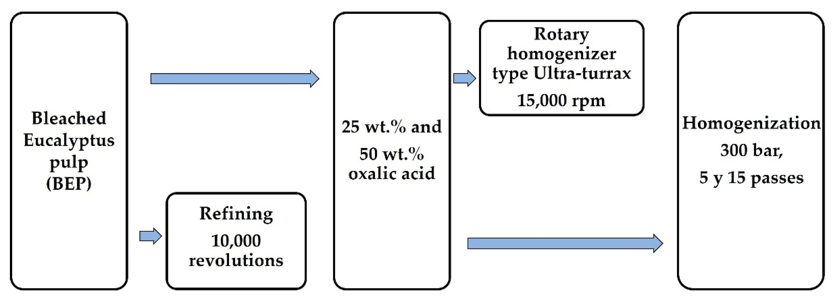
2.1. CMNF Preparation
2.1.1. Chemical Pre-Treatment
2.1.2. Mechanical Pre-Treatment
2.1.3. Mechanical Fibrillation
2.2. Characterization of CMNFs
2.2.1. Esterification and Carboxylation
2.2.2. Nanofibrillation Yield, Transmittance and Surface Charges
2.2.3. Morphologies
Measurements of Diameter and Length Distributions by Microscopy
Sedimentation
Shear Viscosity
2.3. Film Formation from CMNFs
3. Results
3.1. CMNF Characterization
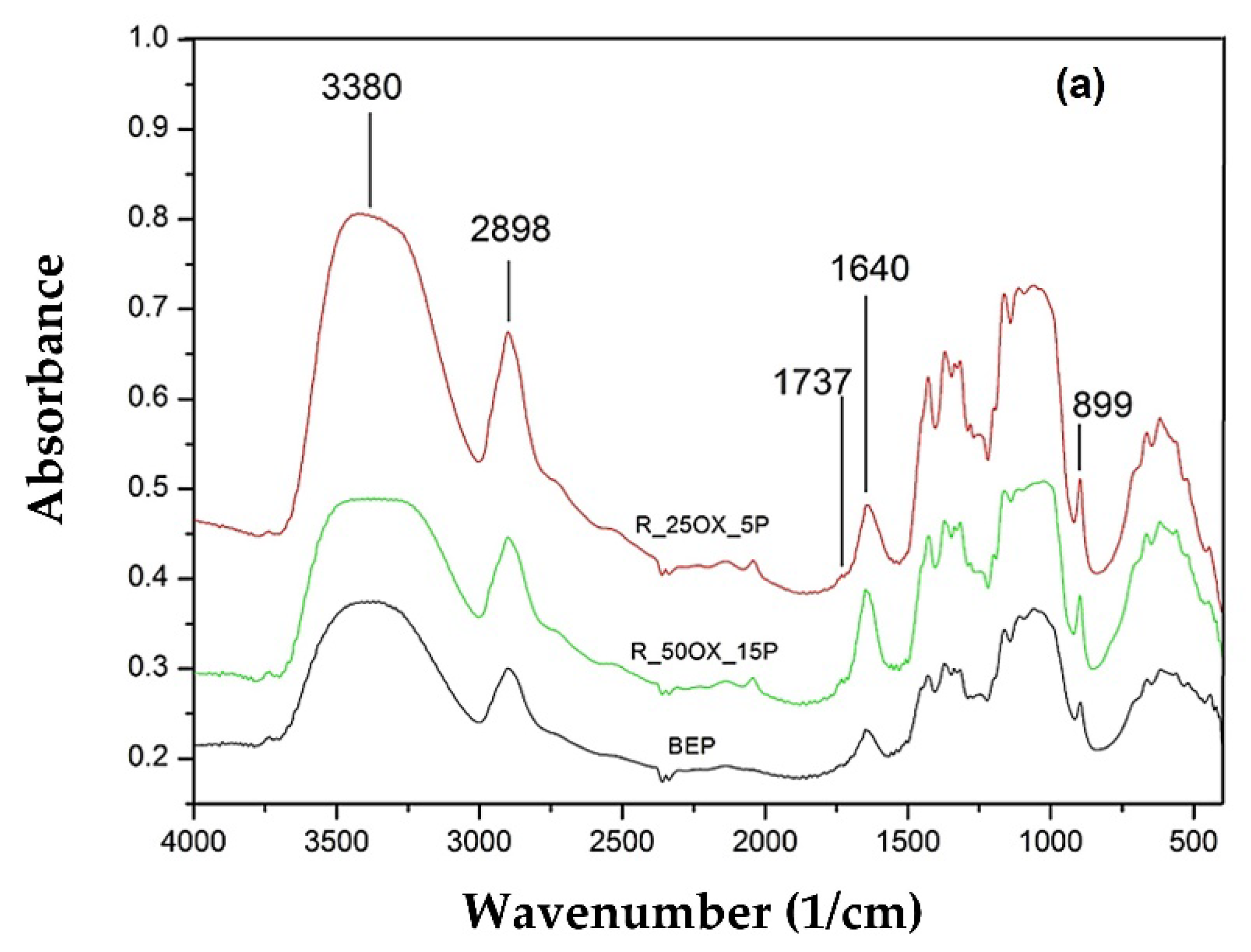
3.1.1. Esterification and Carboxylation
3.1.2. Nanofibrillation Yield, Transmittance and Surface Charge
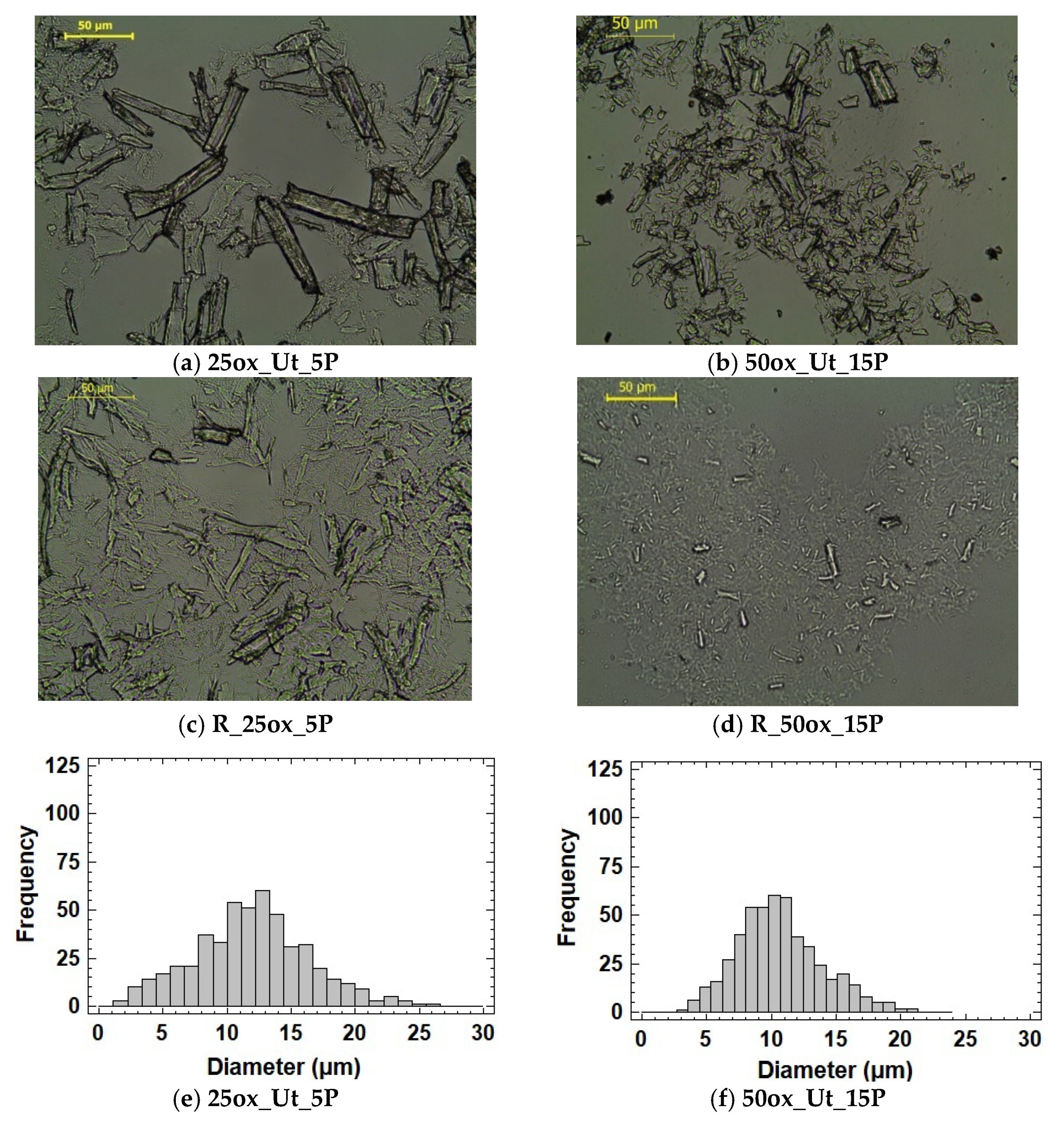
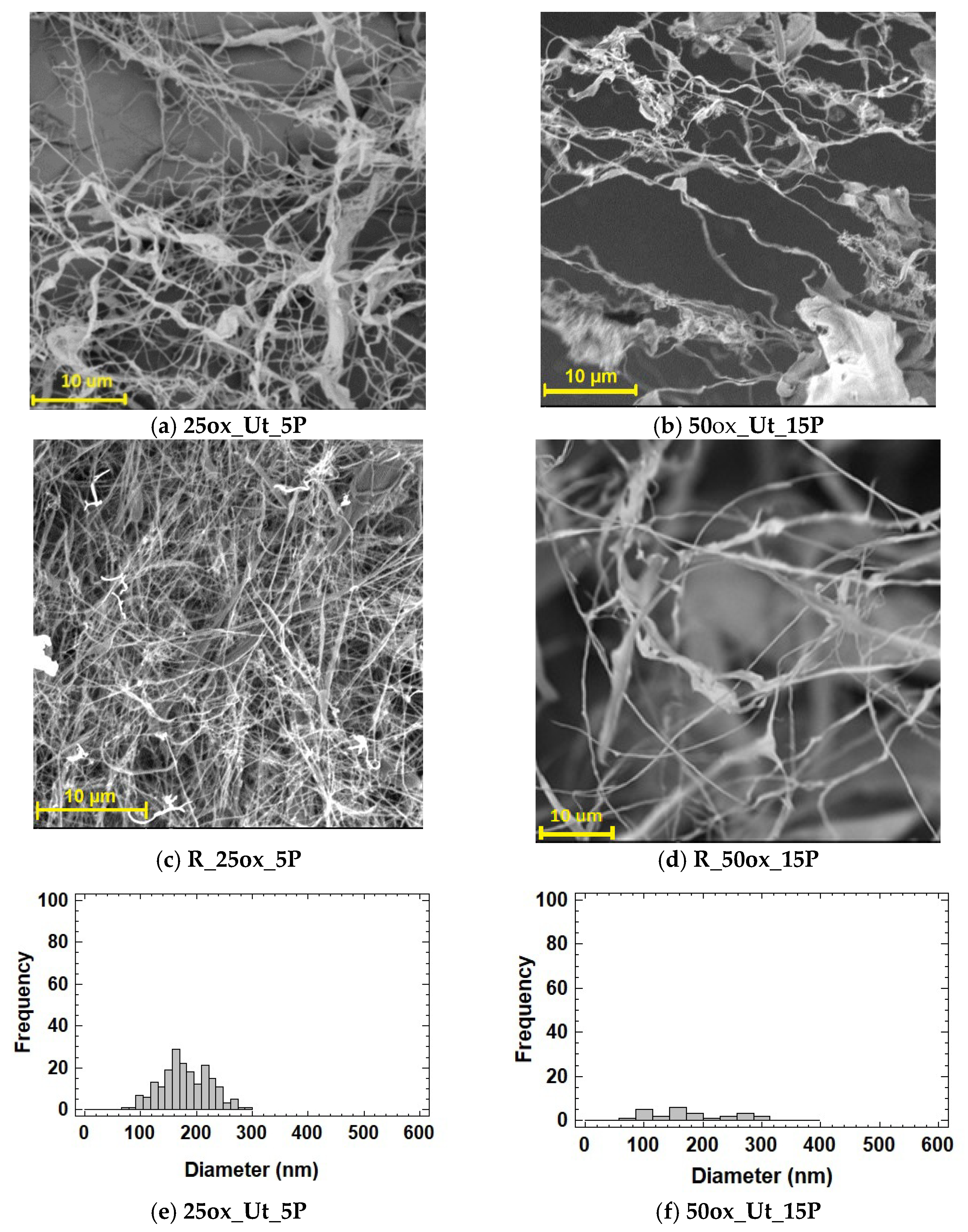
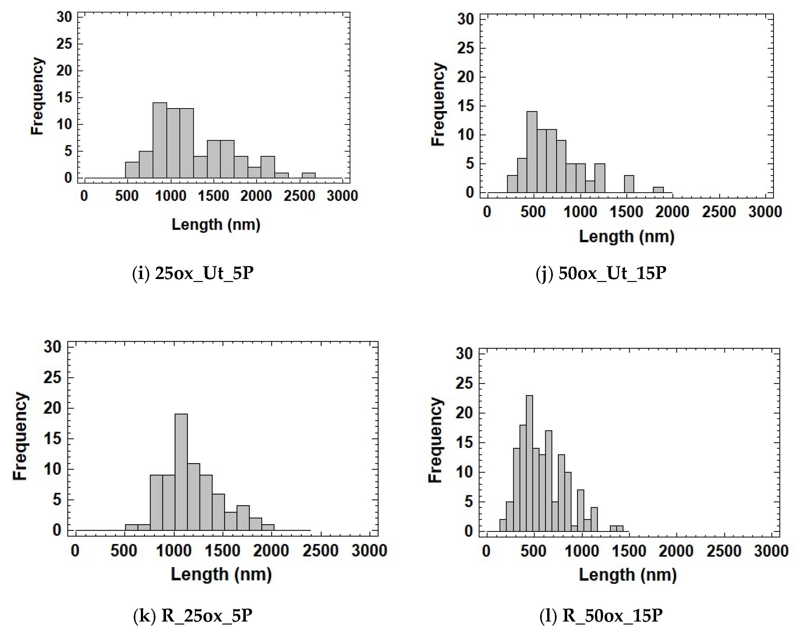
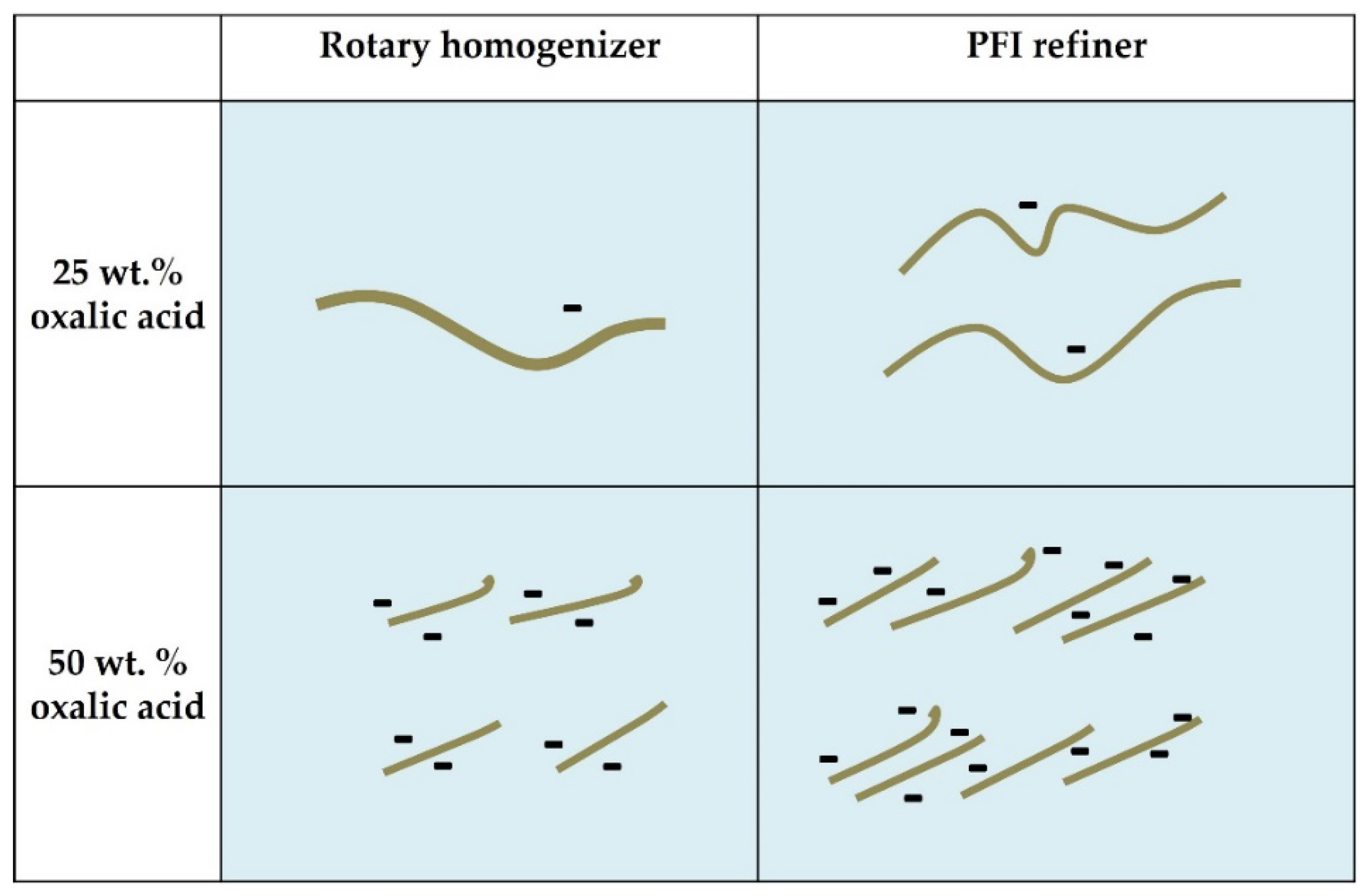
3.1.3. Morphologies
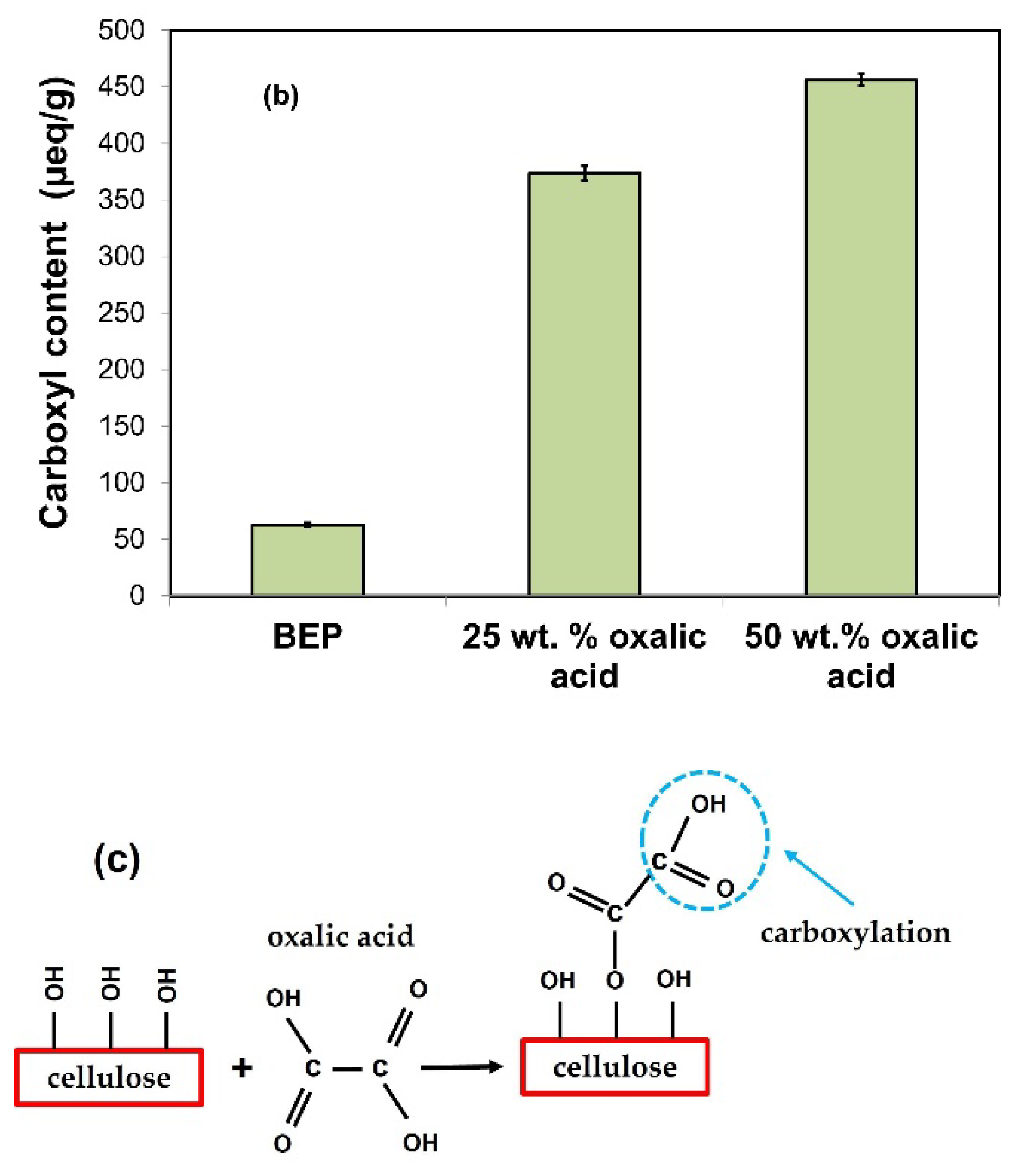
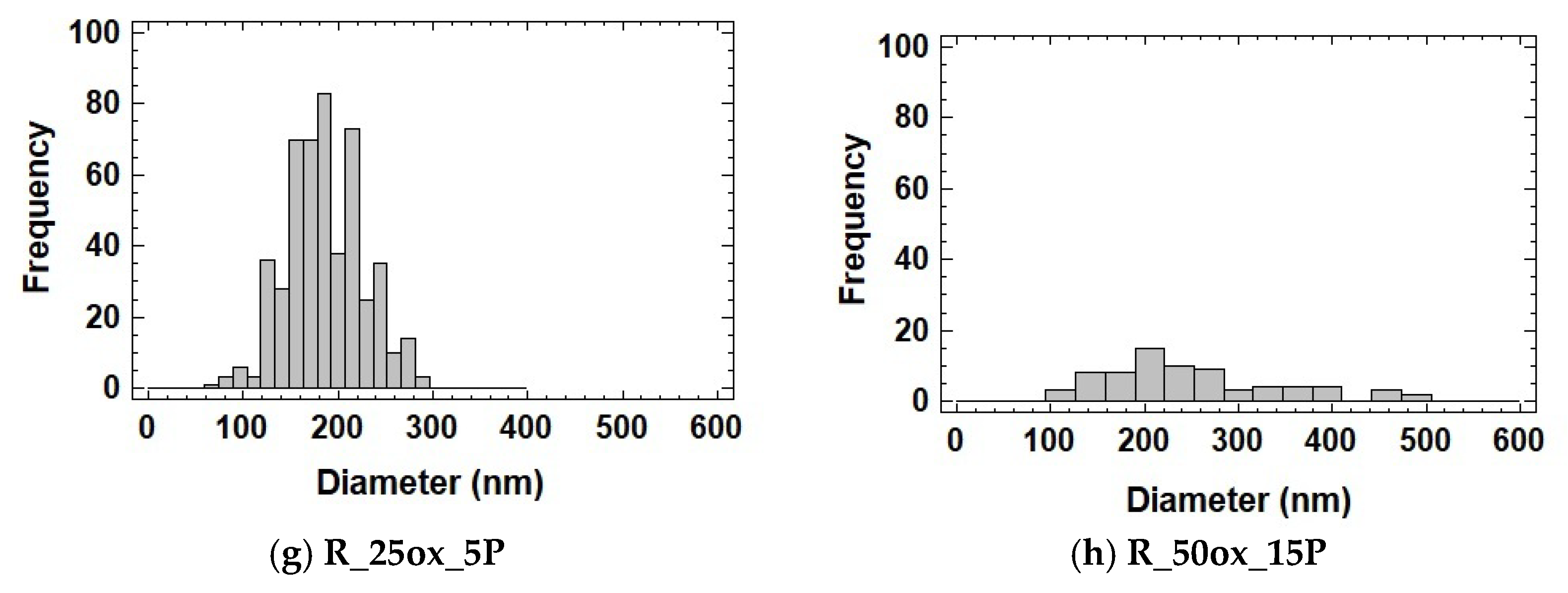
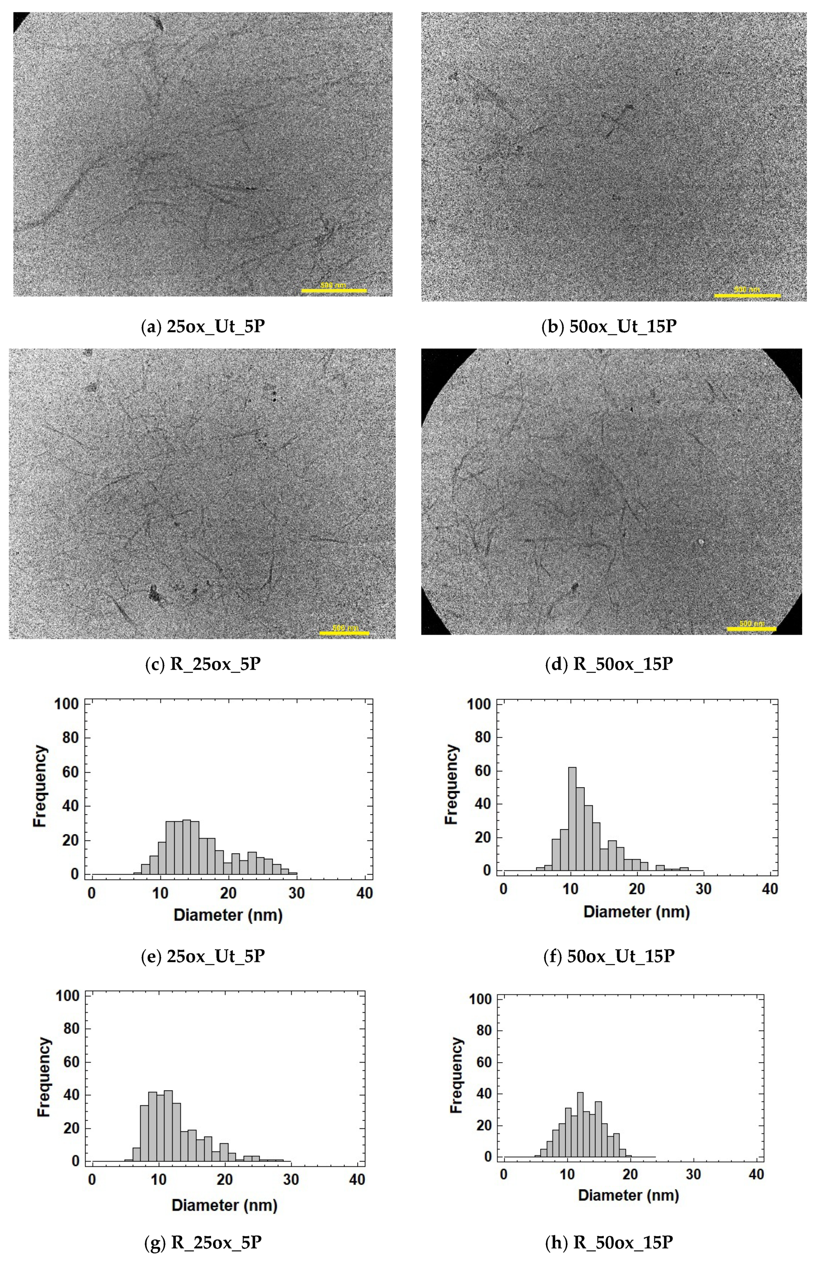
Measurement of Diameter and Length Distributions by Microscopy
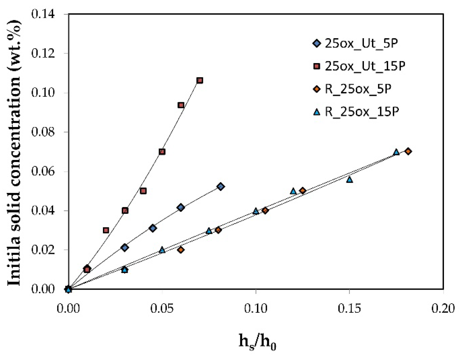
Sedimentation
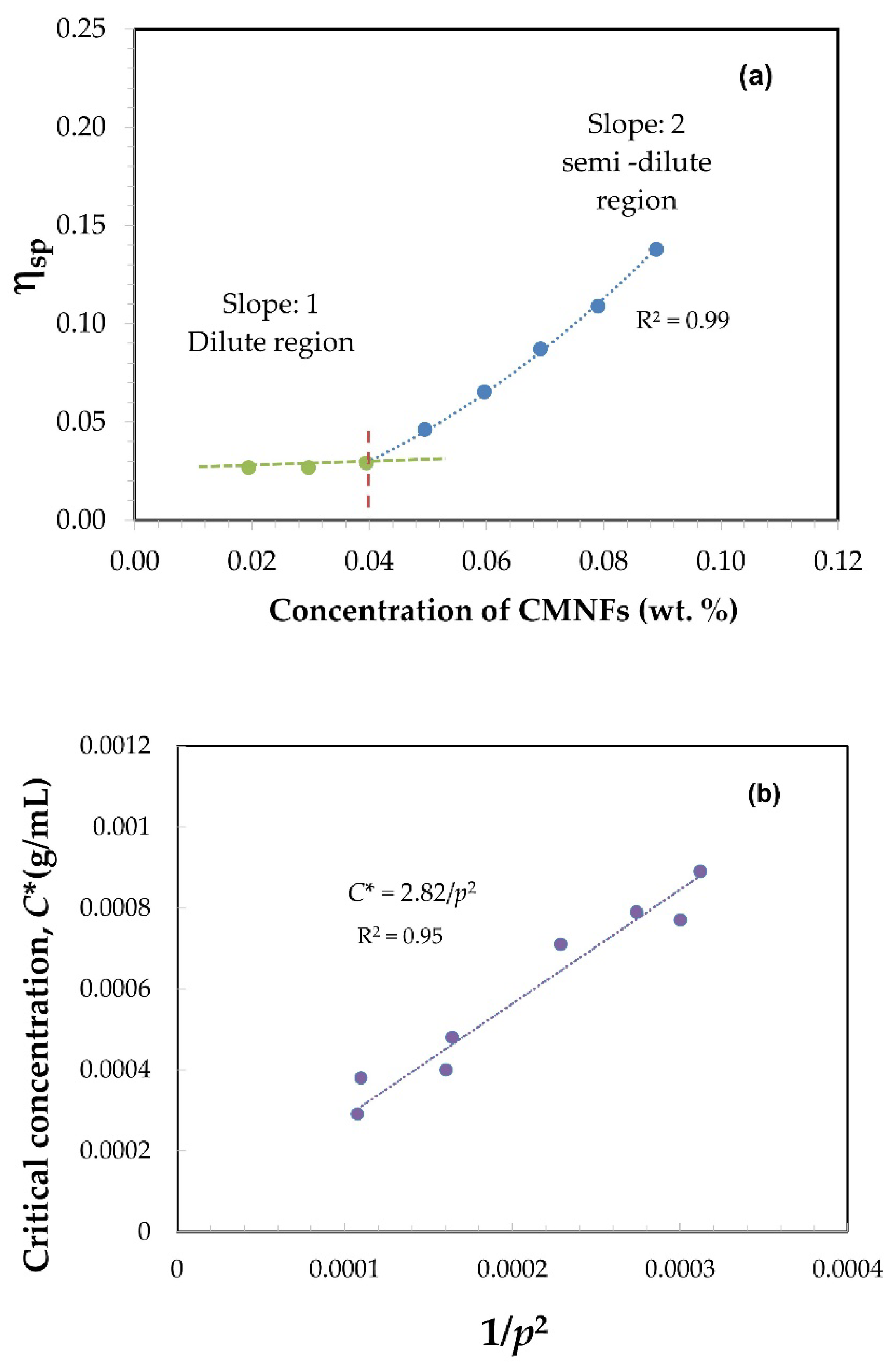
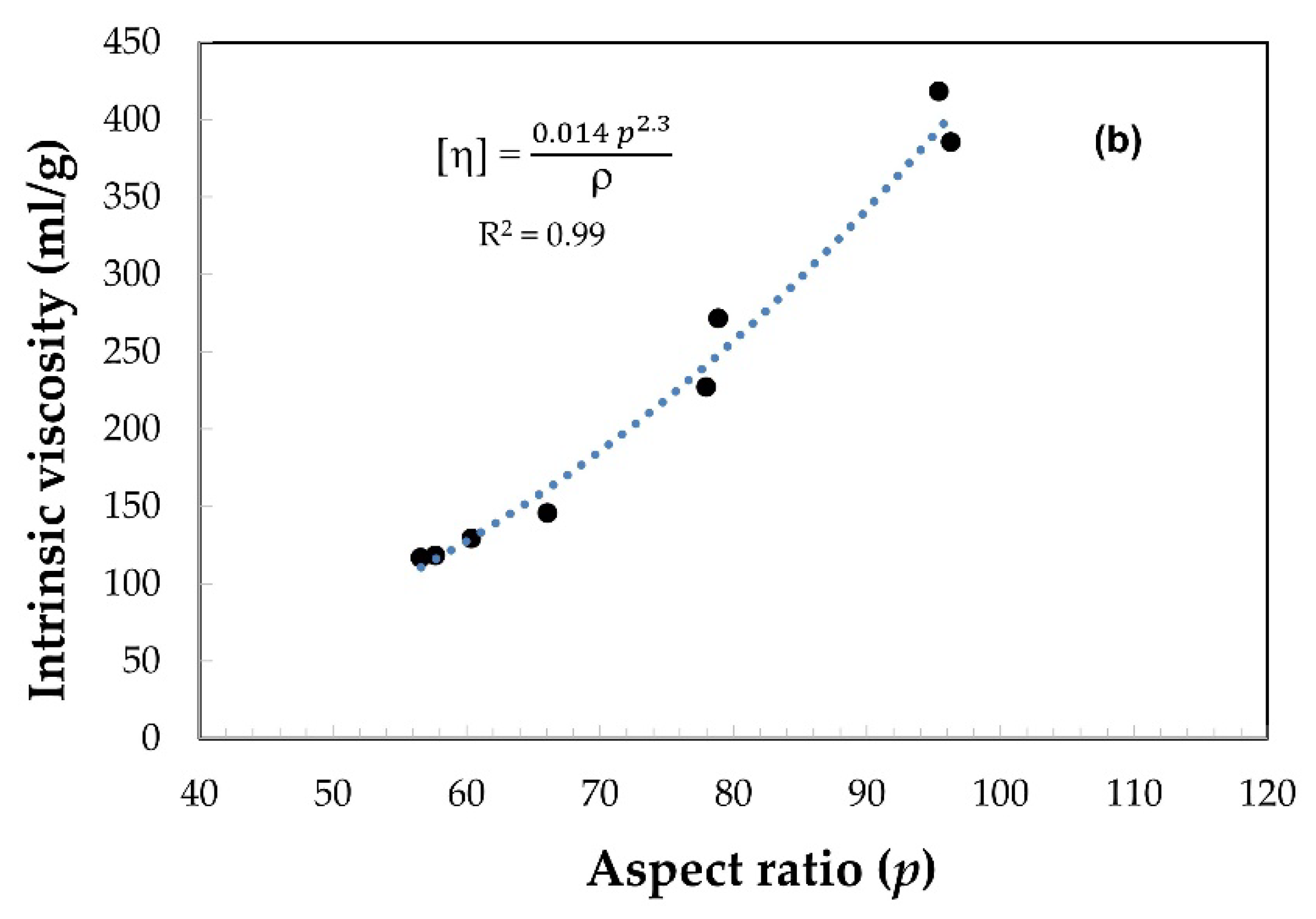
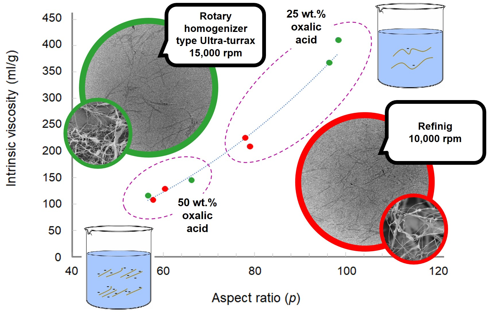
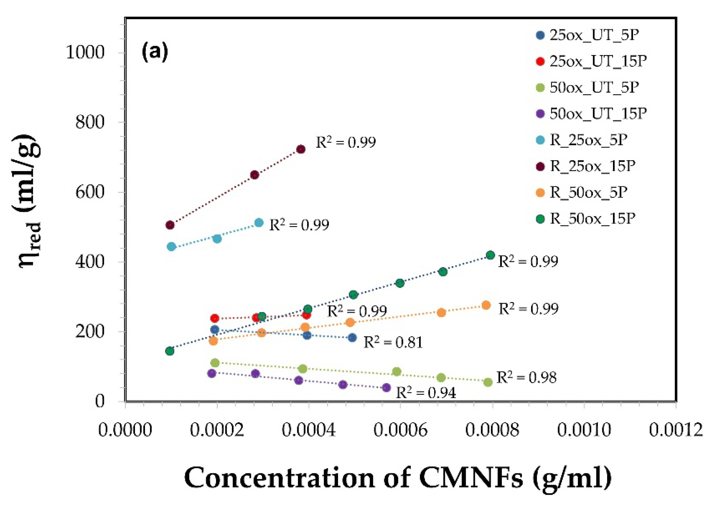
Shear Viscosity
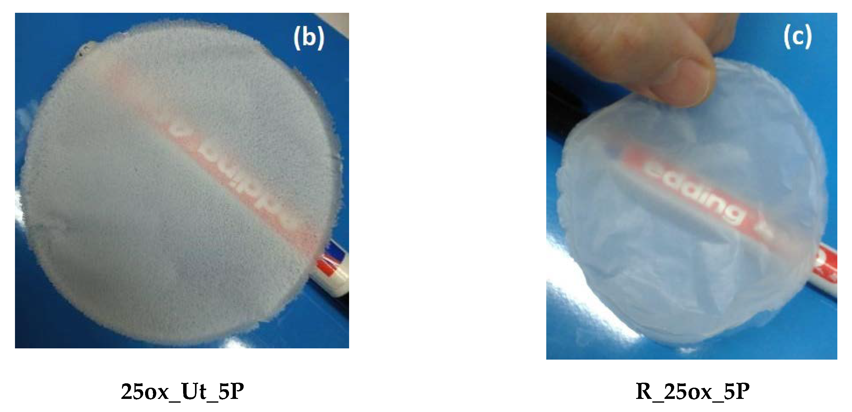
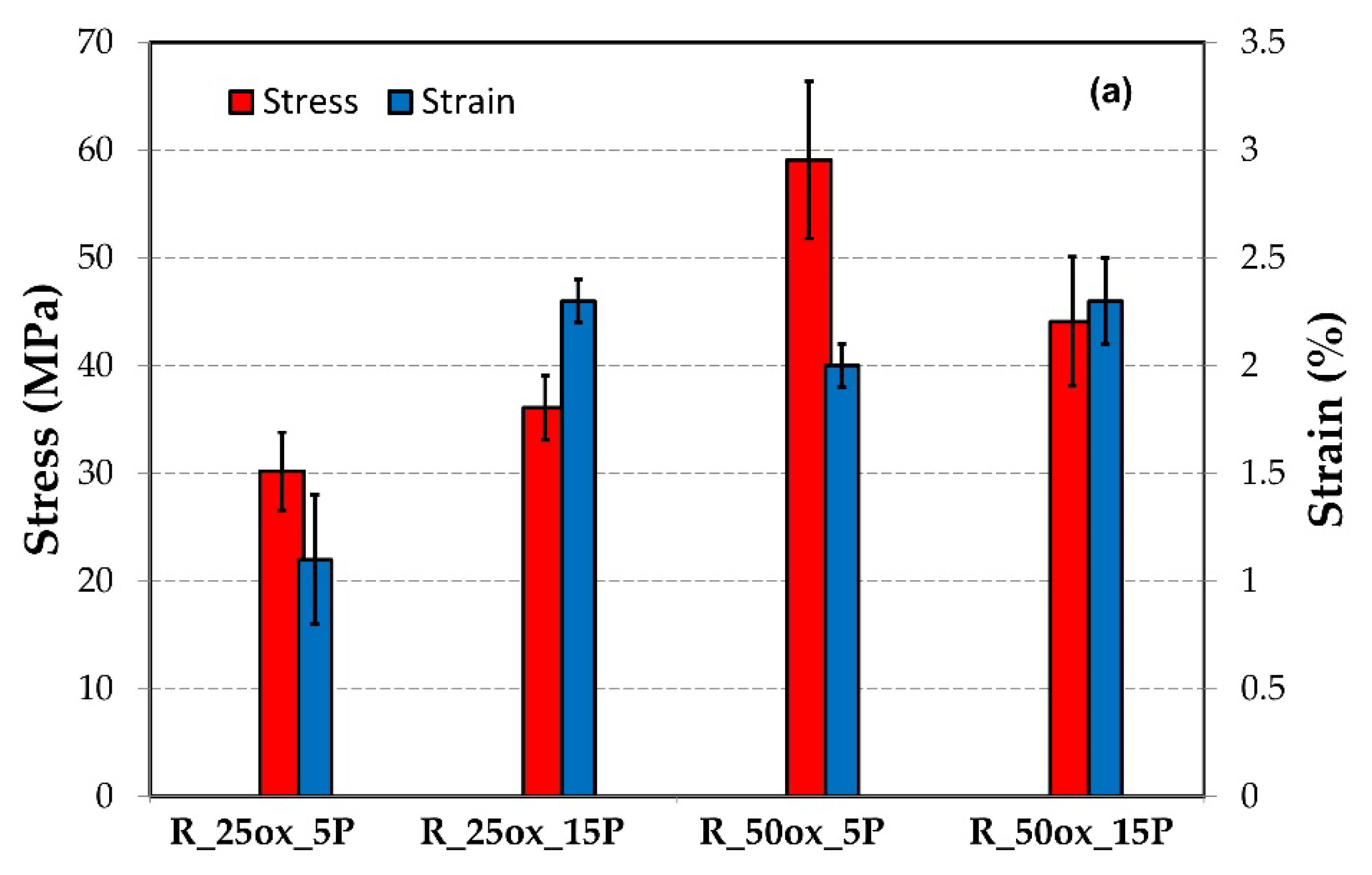
3.2. Film Formation of CMNFs
4. Conclusions
Supplementary Materials
Author Contributions
Funding
Institutional Review Board Statement
Informed Consent Statement
Data Availability Statement
Acknowledgments
Conflicts of Interest
References
- Siró, I.; Plackett, D. Microfibrillated cellulose and new nanocomposite materials: A review. Cellulose 2010, 17, 459–494. [Google Scholar] [CrossRef]
- Habibi, Y.; Lucian, L.A.; Rojas, O.J. Cellulose nanocrystals: Chemistry, self-assembly, and applications. Chem. Rev. 2010, 110, 3479–3500. [Google Scholar] [CrossRef]
- Xie, H.; Du, H.; Yang, X.; Si, C. Recent Strategies in Preparation of Cellulose Nanocrystals and Cellulose Nanofibrils Derived from Raw Cellulose Materials. Int. J. Polym. Sci. 2018, 5, 7923068. [Google Scholar] [CrossRef]
- Lee, K.Y.; Aitomäki, Y.; Berglund, L.A.; Oksman, K.; Bismarck, A. On the use of nanocellulose as reinforcement in polymer matrix composites. Compos. Sci. Technol. 2014, 105, 15–27. [Google Scholar] [CrossRef]
- Blessy, J.; Sagarika, V.K.; Chinnu, S.; Nandakumar, K.; Sabu, T. Cellulose nanocomposites: Fabrication and biomedical applications. J. Bioresour. Bioprod. 2020, 5, 223–237. [Google Scholar] [CrossRef]
- Hu, F.; Zeng, J.; Cheng, Z.; Wang, X.; Wang, B.; Zeng, Z.; Chen, K. Cellulose nanofibrils (CNFs) produced by different mechanical methods to improve mechanical properties of recycled paper. Carbohydr. Polym. 2021, 254, 117474. [Google Scholar] [CrossRef]
- Chen, Y.; Zhang, L.; Yang, Y.; Pang, B.; Xu, W.; Duan, G.; Jiang, S.; Zhang, K. Recent progress on nanocellulose aerogels: Preparation, modification, composite fabrication, applications. Adv. Mater. 2021, 33, 2005569. [Google Scholar] [CrossRef]
- Ang, S.; Haritos, V.; Batchelor, W. Effect of refining and homogenization on nanocellulose fiber development, sheet strength and energy consumption. Cellulose 2019, 26, 4767–4786. [Google Scholar] [CrossRef]
- Ferrer, A.; Filpponen, I.; Rodrıguez, A.; Laine, J.; Rojas, O.J. Valorization of residual empty palm fruit bunch fibers (EPFBF) by microfluidization: Production of nanofibrillated cellulose and EPFBF nanopaper. Bioresour. Technol. 2012, 125, 249–255. [Google Scholar] [CrossRef]
- Ehman, N.V.; Lourenço, A.F.; McDonagh, B.H.; Vallejos, M.E.; Felissia, F.E.; Ferreira, P.J.T.; Chinga-Carrasco, G.; Area, M.C. Influence of initial chemical composition and characteristics of pulps on the production and properties of lignocellulosic nanofibers. Int. J. Biol. Macromol. 2020, 143, 453–461. [Google Scholar] [CrossRef]
- Ho, T.T.T.; Abe, K.; Zimmermann, T.; Yano, H. Nanofibrillation of pulp fibers by twin-screw extrusion. Cellulose 2015, 22, 421–433. [Google Scholar] [CrossRef]
- Chen, Y.; Zhang, L.; Mei, C.; Li, Y.; Duan, G.; Agarwal, S.; Greiner, A.; Ma, C.; Jiang, S. Wood-inspired anisotropic cellulose nanofibril composite sponges for multifunctional applications. ACS Appl. Mater. Interfaces 2020, 12, 35513–35522. [Google Scholar] [CrossRef]
- Tarrés, Q.; Oliver-Ortega, H.; Boufi, S.; Pèlach, A.; Delgado-Aguilar, M.; Mutjé, P. Evaluation of the fibrillation method on lignocellulosic nanofibers production from eucalyptus sawdust: A comparative study between high-pressure homogenization and grinding. Int. J. Biol. Macromol. 2020, 145, 1199–1207. [Google Scholar] [CrossRef]
- Eyholzer, C.; Bordeanu, N.; Lopez-Suevos, F.; Rentsch, D.; Zimmermann, T.; Oksman, K. Preparation and characterization of water-redispersible nanofibrillated cellulose in powder form. Cellulose 2010, 17, 19–30. [Google Scholar] [CrossRef]
- Ramos Aragão Melo, A.; Dutra Filho, J.C.; Cucinelli Neto, R.P.; Ferreira, W.S.; Soares Archanjo, B.; Verdan Curti, R.; Bruno Tavares, M.I. Effect of Ultra-Turrax on Nanocellulose Produced by Acid Hydrolysis and Modified by Nano ZnO by Sol-Gel Method. Mater. Sci. Appl. 2020, 11, 150–166. [Google Scholar] [CrossRef]
- Saito, T.; Nishiyama, Y.; Putaux, J.L.; Vignon, M.; Isogai, A. Homogeneous suspensions of individualized microfbrils from TEMPO-catalyzed oxidation of native cellulose. Biomacromolecules 2006, 7, 1687–1691. [Google Scholar] [CrossRef]
- Besbes, I.; Alila, S.; Bouf, S. Nanofbrillated cellulose from TEMPO-oxidized eucalyptus fbres: Efect of the carboxyl content. Carbohydr. Polym. 2011, 84, 975–983. [Google Scholar] [CrossRef]
- Mishra, S.P.; Manent, A.S.; Chabot, B.; Daneault, C. The use of sodium chlorite in post-oxidation of TEMPO-oxidized pulp: Effect on pulp characteristics and nanocellulose yield. J. Wood Chem. Technol. 2012, 32, 137–148. [Google Scholar] [CrossRef]
- Sanchez-Salvador, J.L.; Campano, C.; Negro, C.; Monte, M.C.; Blanco, A. Increasing the Possibilities of TEMPO-Mediated Oxidation in the Production of Cellulose Nanofibers by Reducing the Reaction Time and Reusing the Reaction Medium. Adv. Sustain. Syst. 2021, 5, 2000277. [Google Scholar] [CrossRef]
- Ji, H.; Xiang, Z.; Qi, H.; Han, T.; Pranovich, A.; Song, T. Strategy towards one-step preparation of carboxylic cellulose nanocrystals and nanofibrils with high yield, carboxylation and highly stable dispersibility using innocuous citric acid. Green Chem. 2013, 21, 1956–1964. [Google Scholar] [CrossRef]
- Chen, L.; Zhu, J.Y.; Baez, C.; Kitin, P.; Elder, T. Highly thermal-stable and functional cellulose nanocrystals and nanofibrils produced using fully recyclable organic acids. Green Chem. 2016, 18, 3835–3843. [Google Scholar] [CrossRef]
- Zhang, L.; Batchelor, W.; Varanasi, S.; Tsuzuki, T.; Wang, X. Effect of cellulose nanofiber dimensions on sheet forming through filtration. Cellulose 2012, 19, 561–574. [Google Scholar] [CrossRef]
- Varanasi, S.; He, R.; Batchelor, W. Estimation of cellulose nanofibre aspect ratio from measurements of fibre suspension gel point. Cellulose 2013, 20, 1885–1896. [Google Scholar] [CrossRef]
- Martinez, D.M.; Buckley, K.; Jivan, S.; Lindstrom, A.; Thiruvengadaswamy, R.; Olson, J.A.; Ruth, T.J.; Kerekes, R.J. Characterizing the mobility of papermaking fibres during sedimentation. In The Science of Papermaking, Transactions of the 12th Fundamental Research Symposium, Oxford; Baker, C.F., Ed.; The Pulp and Paper Fundamental Research Society: Bury, UK, 2001; pp. 225–254. [Google Scholar] [CrossRef]
- Albornoz-Palma, G.; Betancourt, F.; Mendonça, R.T.; Chinga-Carrasco, G.; Pereira, M. Relationship between rheological and morphological characteristics of cellulose nanofibrils in dilute dispersions. Carbohydr. Polym. 2020, 230, 115588. [Google Scholar] [CrossRef]
- Katz, S.; Beatson, R.P.; Scallan, A.M. The determination of strong and weak acidic groups in sulphite pulps. Sven Papp. 1984, 87, 48–53. [Google Scholar]
- Ovalle-Serrano, S.A.; Gómez, F.N.; Blanco-Tirado, C.; Combariza, M.Y. Isolation and characterization of cellulose nanofibrils from Colombian Fique decortication by-products. Carbohydr. Polym. 2018, 189, 169–177. [Google Scholar] [CrossRef]
- Schnell, C.N.; Tarrés, Q.; Galván, M.V.; Mocchiutti, P.; Delgado-Aguilar, M.; Zanuttini, M.A.; Mutjé, P. Polyelectrolyte complexes for assisting the application of lignocellulosic micro/nanofibers in papermaking. Cellulose 2018, 25, 6083–6092. [Google Scholar] [CrossRef]
- Tanaka, R.; Saito, T.; Ishii, D.; Isogai, A. Determination of nanocellulose fibril length by shear viscosity measurement. Cellulose 2014, 21, 1581–1589. [Google Scholar] [CrossRef]
- Tripathi, A.; Ferrer, A.; Khan, S.A.; Rojas, O.J. Morphological and thermochemical changes upon autohydrolysis and microemulsion treatments of coir and empty fruit bunch residual biomass to isolate lignin-rich micro- and nanofibrillar cellulose. ACS Sustain. Chem. Eng. 2017, 5, 2483–2492. [Google Scholar] [CrossRef]
- Luo, J.; Huang, K.; Xu, Y.; Fan, Y. A comparative study of lignocellulosic nanofibrils isolated from celery using oxalic acid hydrolysis followed by sonication and mechanical fibrillation. Cellulose 2019, 26, 5237–5246. [Google Scholar] [CrossRef]
- Ganan, P.; Cruz, J.; Garbizu, S.; Arbelaiz, A.; Mondragon, M. Stem and bunch banana fibers from cultivation wastes: Effect of treatments on physico-chemical behavior. J. Appl. Polym. Sci. 2004, 94, 1489–1495. [Google Scholar] [CrossRef]
- Jia, C.; Chen, L.; Shao, Z.; Agarwal, U.P.; Hu, L.; Zhu, J.Y. Using a fully recyclable dicarboxylic acid for producing dispersible and thermally stable cellulose nanomaterials from different cellulosic sources. Cellulose 2017, 24, 2483–2498. [Google Scholar] [CrossRef]
- Junka, K.; Filpponen, I.; Lindström, T.; Laine, J. Titrimetric methods for the determination of surface and total charge of functionalized nanofibrillated/ microfibrillated cellulose (NFC/MFC). Cellulose 2013, 20, 2887–2895. [Google Scholar] [CrossRef]
- Lecourt, M.; Sigoillot, J.C.; Petit-Conil, M. Cellulase-assisted refining of chemical pulps: Impact of enzymatic charge and refining intensity on energy consumption and pulp quality. Process biochem. 2010, 45, 1274–1278. [Google Scholar] [CrossRef]
- Sanchez-Salvador, J.L.; Monte, M.C.; Batchelor, W.; Garnier, G.; Negro, C.; Blanco, A. Characterizing highly fibrillated nanocellulose by modifying the gel point methodology. Carbohydr. Polym. 2020, 227, 115340. [Google Scholar] [CrossRef]
- Morris, E.R.; Cutler, A.N.; Ross-Murphy, S.B.; Rees, D.A.; Price, J. Concentration and shear rate dependence of viscosity in random coil polysaccharide solutions. Carbohydr. Polym. 1981, 1, 5–21. [Google Scholar] [CrossRef]
- Haward, S.J.; Sharma, V.; Butts, C.P.; McKinley, G.H.; Rahatekar, S.S. Shear and extensional rheology of cellulose/ionic liquid solutions. Biomacromolecules 2012, 13, 1688–1699. [Google Scholar] [CrossRef]
- Mason, S.G. The motion of fibers in flowing liquids. Pulp Pap. Mag. Can. 1950, 51, 93–100. [Google Scholar]
- Tanaka, R.; Saito, T.; Hondo, H.; Isogai, A. Influence of Flexibility and Dimensions of Nanocelluloses on the Flow Properties of Their Aqueous Dispersions. Biomacromolecules 2015, 16, 2127–2131. [Google Scholar] [CrossRef]
- Switzer, L.H., III; Klingenberg, D.J. Rheology of sheared flexible fiber suspensions via fiber-level simulations. Inc. J. Rheol. 2003, 47, 759–778. [Google Scholar] [CrossRef]


| Samples | PFI Mill Refining (Revolutions) | Oxalic Acid (wt.%) | Homogenizer Type Ultra-Turrax, 3 min/g Fiber (rpm) | Homogenization at 300 bar (Passes) |
|---|---|---|---|---|
| 25ox_Ut_5P | --- | 25 | 15,000 | 5 |
| 25ox_Ut_15P | --- | 25 | 15,000 | 15 |
| 50ox_Ut_5P | --- | 50 | 15,000 | 5 |
| 50ox_Ut_15P | --- | 50 | 15,000 | 15 |
| R_25ox_5P | 10,000 | 25 | --- | 5 |
| R_25ox_15P | 10,000 | 25 | --- | 15 |
| R_50ox_5P | 10,000 | 50 | --- | 5 |
| R_50ox_15P | 10,000 | 50 | --- | 15 |
| CMNF | Nanofibrillation Yield (%) 1 | Transmittance (800 nm) (%) | Surface Charge (µeq/g CMNF) 1 |
|---|---|---|---|
| 25ox_Ut_5P | 4.5 ± 1.2 | 14.5 | 10.3 ± 0.9 |
| 25ox_Ut_15P | 5.1 ± 1.6 | 10.6 | 11.8 ± 0.1 |
| 50ox_Ut_5P | 19.5 ± 1.4 | 8.4 | 18.5 ± 2.1 |
| 50ox_Ut_15P | 20.6 ± 1.6 | 10.1 | 30.5 ± 1.5 |
| R_25ox_5P | 11.6 ± 1.2 | 18.7 | 19.6 ± 1.9 |
| R_25ox_15P | 12.8 ± 1.8 | 22.4 | 21.7 ± 0.2 |
| R_50ox_5P | 54.3 ± 0.33 | 48.3 | 72.9 ± 0.3 |
| R_50ox_15P | 76.5 ± 0.28 | 72.1 | 71.0 ± 0.6 |
| CMNF | Average Diameter (µm) 1 | Average Length (µm) 2 | Average Aspect Ratio (Length/Diameter) |
|---|---|---|---|
| BEP | 15.6 ± 4.0 | 945.3 ± 271.4 | 60.4 |
| 25ox_Ut_5P | 11.9 ± 4.5 | 63.9 ± 17.2 | 5.4 |
| 25ox_Ut_15P | 10.6 ± 3.3 | 42.6 ± 14.9 | 4.2 |
| 50ox_Ut_5P | 10.9 ± 3.4 | 32.0 ± 7.8 | 2.9 |
| 50ox_Ut_15P | 10.7 ± 3.3 | 29.1 ± 7.2 | 2.7 |
| R_25ox_5P | 3.9 ± 3.6 | 48.7 ± 28.4 | 14.1 |
| R_25ox_15P | 3.3 ± 2.5 | 25.6 ± 13.3 | 7.8 |
| R_50ox_5P | 2.8 ± 1.0 | 11.1 ± 5.5 | 4.0 |
| R_50ox_15P | 2.1 ± 1.0 | 7.7 ± 2.7 | 3.6 |
| CMNF | Average Diameter (µm) 1 |
|---|---|
| 25ox_Ut_5P | 179 ± 43 |
| 25ox_Ut_15P | 257 ± 69 |
| 50ox_Ut_5P | 220 ± 74 |
| 50ox_Ut_15P | 180 ± 71 |
| R_25ox_5P | 186 ± 40 |
| R_25ox_15P | 252 ± 68 |
| R_50ox_5P | 193 ± 95 |
| R_50ox_15P | 226 ± 69 |
| CNF | Average Diameter CNF (nm) 1 | Average Length (nm) 2 | Average Aspect Ratio (Length/Diameter) |
|---|---|---|---|
| 25ox_Ut_5P | 16.0 ± 5.0 | 1262 ± 443 | 78.9 |
| 25ox_Ut_15P | 16.0 ± 4.8 | 1250 ± 430 | 78.0 |
| 50ox_Ut_5P | 12.0 ± 3.0 | 725 ± 248 | 60.4 |
| 50ox_Ut_15P | 12.6 ± 3.7 | 727 ± 322 | 57.7 |
| R_25ox_5P | 12.5 ± 4.2 | 1204 ± 298 | 96.3 |
| R_25ox_15P | 13.2 ± 3.5 | 1298 ± 569 | 98.3 |
| R_50ox_5P | 12.0 ± 3.5 | 793 ± 227 | 66.1 |
| R_50ox_15P | 12.5 ± 3.0 | 707 ± 183 | 56.6 |
| CMNF | Y = Ax2 + Bx (*) | Gel Point (Cc) (wt.%) (**) | Aspect Ratio (A) (Length/Diameter) |
|---|---|---|---|
| 25ox_Ut_5P | y = −1.861x2 + 0.794x | 0.794 | 67.3 |
| 25ox_Ut_15P | y = 10.99x2 + 0.793x | 0.793 | 67.4 |
| R_25ox_5P | y = 0.178x2 + 0.361x | 0.361 | 99.9 |
| R_25ox_15P | y = −0.044x2 + 0.401x | 0.401 | 94.8 |
| CMNF | Critical Concentration (C*) CMNF (wt.%) | Intrinsic Viscosity CMNF (mL/g) |
|---|---|---|
| 25ox_Ut_5P | 0.040 | 187.9 |
| 25ox_Ut_15P | 0.048 | 225.4 |
| 50ox_Ut_5P | 0.079 | 129.1 |
| 50ox_Ut_15P | 0.077 | 108.1 |
| R_25ox_5P | 0.029 | 367.6 |
| R_25ox_15P | 0.038 | 410.5 |
| R_50ox_5P | 0.071 | 145.5 |
| R_50ox_15P | 0.089 | 115.9 |
Publisher’s Note: MDPI stays neutral with regard to jurisdictional claims in published maps and institutional affiliations. |
© 2022 by the authors. Licensee MDPI, Basel, Switzerland. This article is an open access article distributed under the terms and conditions of the Creative Commons Attribution (CC BY) license (https://creativecommons.org/licenses/by/4.0/).
Share and Cite
Bastida, G.A.; Schnell, C.N.; Mocchiutti, P.; Solier, Y.N.; Inalbon, M.C.; Zanuttini, M.Á.; Galván, M.V. Effect of Oxalic Acid Concentration and Different Mechanical Pre-Treatments on the Production of Cellulose Micro/Nanofibers. Nanomaterials 2022, 12, 2908. https://doi.org/10.3390/nano12172908
Bastida GA, Schnell CN, Mocchiutti P, Solier YN, Inalbon MC, Zanuttini MÁ, Galván MV. Effect of Oxalic Acid Concentration and Different Mechanical Pre-Treatments on the Production of Cellulose Micro/Nanofibers. Nanomaterials. 2022; 12(17):2908. https://doi.org/10.3390/nano12172908
Chicago/Turabian StyleBastida, Gabriela Adriana, Carla Natalí Schnell, Paulina Mocchiutti, Yamil Nahún Solier, María Cristina Inalbon, Miguel Ángel Zanuttini, and María Verónica Galván. 2022. "Effect of Oxalic Acid Concentration and Different Mechanical Pre-Treatments on the Production of Cellulose Micro/Nanofibers" Nanomaterials 12, no. 17: 2908. https://doi.org/10.3390/nano12172908
APA StyleBastida, G. A., Schnell, C. N., Mocchiutti, P., Solier, Y. N., Inalbon, M. C., Zanuttini, M. Á., & Galván, M. V. (2022). Effect of Oxalic Acid Concentration and Different Mechanical Pre-Treatments on the Production of Cellulose Micro/Nanofibers. Nanomaterials, 12(17), 2908. https://doi.org/10.3390/nano12172908