Article

Enhanced Electrical Performance and Stability of Solution-Processed Thin-Film Transistors with In2O3/In2O3:Gd Heterojunction Channel Layer

1
College of Engineering Physics, Shenzhen Technology University, Shenzhen 518118, China
2
School of Physics and Electronics, Henan University, Kaifeng 475004, China
*
Author to whom correspondence should be addressed.
Nanomaterials 2022, 12(16), 2783; https://doi.org/10.3390/nano12162783
Submission received: 22 July 2022 / Revised: 4 August 2022 / Accepted: 8 August 2022 / Published: 14 August 2022

Abstract

:
The use of the semiconductor heterojunction channel layer has been explored as a method for improving the performance of metal oxide thin-film transistors (TFTs). The excellent electrical performance and stability of heterojunction TFTs is easy for vacuum-based techniques, but difficult for the solution process. Here, we fabricated In2O3/In2O3:Gd (In2O3/InGdO) heterojunction TFTs using a solution process and compared the electrical properties with single-layer In2O3 TFTs and In2O3:Gd (InGdO) TFTs. The In2O3/InGdO TFT consisted of a highly conductive In2O3 film as the primary transmission layer and a subconductive InGdO film as the buffer layer, and exhibited excellent electrical performance. Furthermore, by altering the Gd dopant concentration, we obtained an optimal In2O3/InGdO TFT with a higher saturation mobility (µ) of 4.34 cm2V−1s−1, a near-zero threshold voltage (Vth), a small off-state current (Ioff) of 1.24 × 10 9 A, a large on/off current ratio (Ion/Ioff) of 3.18 × 10 5 , a small subthreshold swing (SS), and an appropriate positive bias stability (PBS). Finally, an aging test was performed after three months, indicating that In2O3/InGdO TFTs enable long-term air stability while retaining a high-mobility optimal switching property. This study suggests that the role of a high-performance In2O3/InGdO heterojunction channel layer fabricated by the solution process in the TFT is underlined, which further explores a broad pathway for the development of high-performance, low-cost, and large-area oxide electronics.

1. Introduction

Metal oxide thin-film transistors (MO TFTs) have attracted considerable attention because of their high carrier mobilities, excellent optical transparency, good environmental stability, and low temperature processing in active-matrix liquid crystal displays (AMLCD), active-matrix organic light-emitting diode (AMOLED) displays, and other optoelectronic devices [1,2,3]. At present, various metal oxides have been extensively investigated as channel layers for TFTs and exhibit a superior performance, such as In2O3, ZnO, InZnO, InGaZnO, etc. [4,5,6,7,8]. Among them, In2O3 is widely considered to be an ideal candidate to fabricate high-electrical-performance TFTs, owing to its wide band gap, low temperature processability [9], and high field effect carrier mobility due to the efficient percolation pathway of the In 5s orbital. However, the low on/off current ratio (Ion/Ioff), large subthreshold swing (SS), large negative threshold voltage (Vth), and poor bias reliability in the intrinsic In2O3 TFTs limit their industrial applications in the next generation of display technologies [10,11]. To overcome this issue, the proper dopant as a carrier suppressor is indispensable [12]. Choosing an appropriate dopant depends generally on electronegativity; the large difference in electronegativity between the dopant and oxygen helps form strong metal–oxygen bonds [13], which is the critical factor for enhancing the stability and performance of the MO TFTs [12]. Nowadays, the effects of carrier suppressors such as Ga, Zr, Hf, Gd, Y and Al on thin films and devices were broadly investigated [14,15,16,17]. Additionally, the results reveal that the carrier suppressors can help reduce the instability because they can effectively repress the generation of oxygen vacancy by binding strongly to oxygen [8,12,17,18,19] Recently, Gd has been selected as a superb dopant candidate in view of its lower electronegativity of 1.20 compared with indium [13]. This is consistent with the earlier research that incorporated Gd in In2O3 to significantly improve the electrical properties of In-based TFTs [13]. Nevertheless, the incorporation of carrier suppressors in the semiconducting film leads to the degradation of mobility because oxygen vacancies also act as carrier electron donors through their ionization; simultaneously, the threshold voltage shifts to higher values [20]. Recently, a heterojunction channel structure was successfully implemented by combining two different compositions of semi-conducted thin-film channel layers, such as IGZO/IGZO: Ti [21], VZTO/ZTO [20], InZnO/AlSnZnInO [22], In2O3/ZnO [5], AZO/ZO [16], ZnO/IGO [23], In2O3/IGZO [24], ZnO/In2O3 [25], and MgZnO/ZnO [26]. These studies indicate that the heterojunction channel layer comprising a highly conductive layer with high mobility and the semiconducting layer with low Ioff and high stability have been resolved to upgrade the electrical performance and stability [4,26,27,28]. In general, the predominant techniques for depositing oxide films are vacuum-based techniques, such as RF magnetron sputtering, atomic layer deposition, pulse laser deposition, etc. [7,29,30]. These pose some limitations in mass production and the realization of low-cost electronic devices. Fortunately, the solution process has been extensively employed for simplicity, the low-cost fabrication of large areas, easy controllability of chemical stoichiometry, and mass productivity [3,31,32]. Excellent electrical performance and stability of TFTs with the heterojunction channel layer would be easy for the vacuum sputtering deposition process, but difficult for the solution process. Some attempts in this direction have not shown significant improvement in contrast to single-layer channel TFTs.
In this paper, we investigated the impact of Gd doping on the electrical performance of the In2O3 TFTs by the solution process. Then, the In2O3/InGdO TFTs were constructed and contrasted to single-layer In2O3 or InGdO TFTs to validate the vantages of the bilayer structure. Finally, we optimized the electrical performance of the In2O3/InGdO TFTs by varying the Gd doping concentration and reported a comprehensive high performance TFT with a higher mobility of 4.34 cm2V−1s−1, a near-zero Vth, a small Ioff of 1.24 × 10 9   A, a large Ion/Ioff of 3.18 × 10 5 , a small SS and an appropriate PBS. Finally, an aging test was carried out after three months, indicating the excellent environmental stability of the devices.

2. Experimental Section

The In2O3 precursor solution was prepared by dissolving 99.99% purity Indium nitrate hydrate (In(NO3)3.xH2O) in 2-methoxyethanol to yield a 0.05 M solution. InGdO precursor solution with different Gd doping concentrations was separately prepared by dissolving 99.99% purity In(NO3)3.xH2O in 2-methoxyethanol with moderate gadolinium nitrate hexahydrate (Gd(NO3)3.6H2O) to yield a 0.05 M solution. All reagents were purchased from Aladdin (Shanghai, China) and used without further purification. Precursor solutions were stirred overnight at room temperature, and then filtered through a 0.2 μm PTFE membrane filter before spin coating.
The TFTs were fabricated on n-type Si substrates with thermally grown SiO2 (300 nm) as the gate insulator. Before the active layer deposition, the substrate was ultrasonically cleaned in acetone, ethanol and deionized water, sequentially, for 10 min each, and dried it using high purity N2. To improve the chemical compatibility between the interface of the SiO2 and the semiconductor layer, the surface of the cleaned substrate was hydrophilized for 10 min with O2 plasma. For the In2O3/InGdO TFTs, the In2O3 precursor solution was filtered, spin-coated onto the SiO2 at 3000 rpm for 30 s, and then annealed on a hotplate at 300 °C for 20 min. The thicknesses of the In2O3 layer were controlled by repeating the procedure. Subsequently, the InGdO precursor solution was immediately spin-coated onto the In2O3 film to avoid contamination and annealed under the same conditions. The In2O3 and InGdO films have a similar thickness of about 10 nm measured by surface profilometer. Finally, the 80 nm Al source and drain electrodes were thermally evaporated onto the semiconductor layer through a shadow mask that has a channel width (W) and length (L) of 600 and 100 µm, respectively. Similarly, the single-layer In2O3 or InGdO TFTs were fabricated for comparison. The schematics cross-sectional view of the single-layer In2O3 or InGdO and the In2O3/InGdO heterojunction TFTs are shown in Figure 1a,b. The crystallinity of the films was investigated by X-ray diffraction (XRD, Karlsruhe, Germany) with Cu Kα radiation. The surface morphologies and roughness of the films were studied by atomic force microscopy (AFM, Santa Barbara, CA, USA). The electrical characterization of TFTs was performed by using the semiconductor parameter analyzer (Keithley 2612B, Cleveland, OH, USA).

3. Result and Discussion

Figure 1a,b show the schematic cross-sectional view of the TFTs. The crystallinities of the In2O3, InGdO and In2O3/InGdO films annealed at the identical temperature were measured by XRD, as shown in Figure 1c. A nanocrystalline structure with a relatively sharp dominant diffraction peak corresponding to the (222) plane was observed in the In2O3 film. On the other hand, the peak intensity of the InGdO film was significantly diminished compared with that of the In2O3 film. It implies that Gd ions may lead to the degradation of the In2O3 crystallinity to a certain extent, which is consistent with the results of previous studies regarding the disappearance of the peak of InGdO films via Gd doping [13]. However, the diffraction peaks corresponding in the In2O3 and In2O3/InGdO films do not change significantly, which demonstrates that the thinness of the InGdO film cannot affect the underlying In2O3 film. The surface morphology of In2O3, InGdO, and In2O3/InGdO films at 300 °C were checked by AFM and shown in Figure 1d–f, respectively. Based on the AFM results, the root-mean-square (RMS) roughness of In2O3 films over a scan area of 10 μm × 10 μm was 0.598 nm. However, the InGdO film was featureless and smooth, and its RMS roughness was 0.334 nm less than that of In2O3 film. Presumably, the Gd ions in the InGdO film mitigated the degree of random crystallization, leading to the reduced RMS roughness value, which is consistent with the previous report. Additionally, the result was also confirmed from the XRD analysis, as mentioned above. Interestingly, the surface roughness of the In2O3/InGdO film was an equalization between the In2O3 and InGdO films, and its RMS roughness value was 0.495 nm, suggesting that the InGdO capping layer can alleviate In2O3 film roughening during the deposition annealing process at 300 °C.
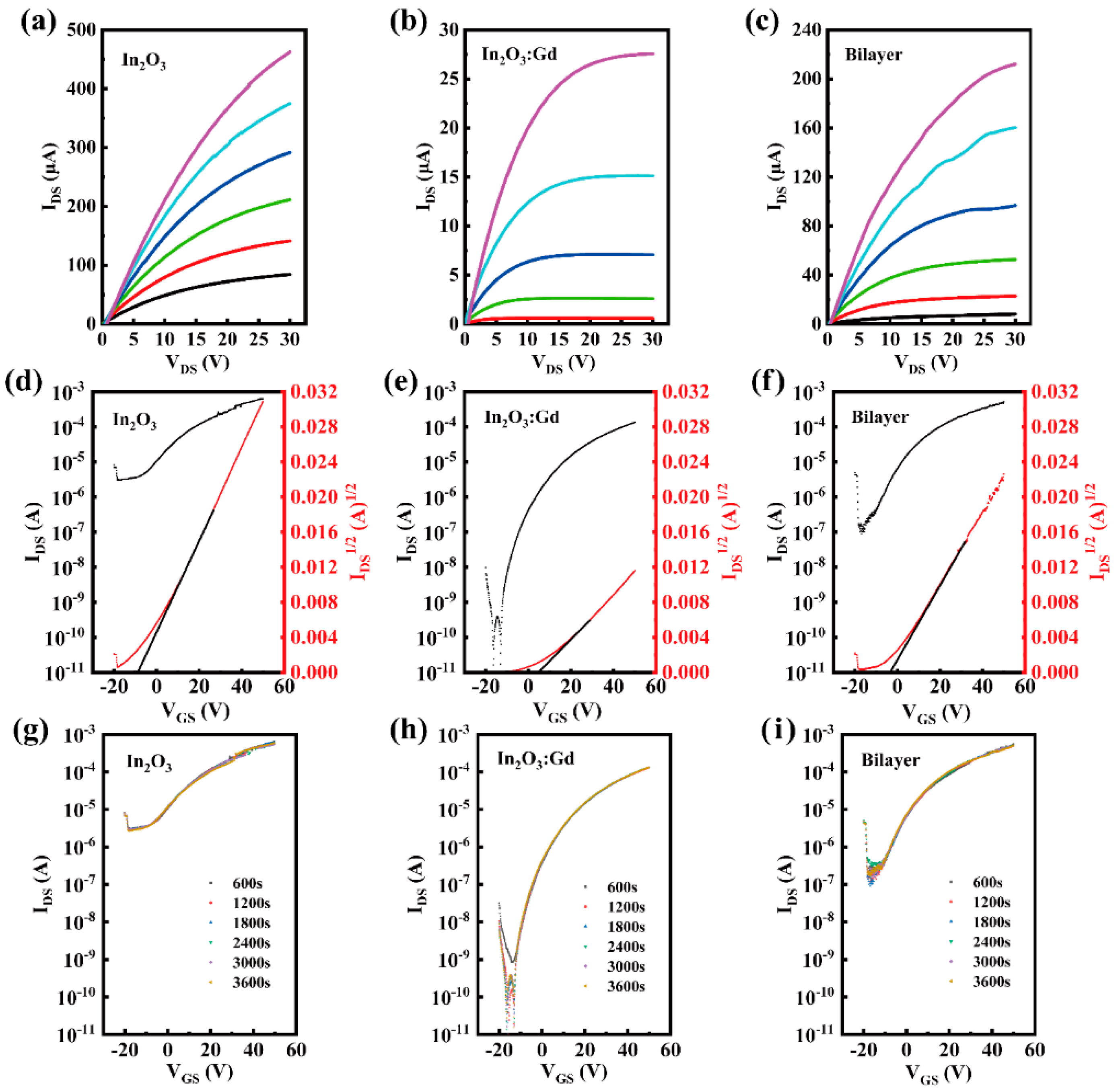
The representative output and transfer curves of TFTs with In2O3 or InGdO single-layer and In2O3/InGdO heterojunction channel layer are shown in Figure 2a–f. The output characteristics of the TFTs were measured by changing the drain voltage (VDS) from 0 to 30 V at different constant gate voltages (VGS) varied from 0 to 30 V in a step of 6 V. The transfer characteristics of TFTs were measured at a VDS of 10 V and a VGS swing from −20~+50 V, whereas the source electrodes were fixed to 0 V. By a linear fit plot of the square root of the IDS versus VGS, the mobility is obtained from the equation:
I DS = ( C i μ W 2 L ) ( V GS V th ) 2
where Ci is the capacitance per unit area of the SiO2 layer, and Vth, VGS, W, and L denote the threshold voltage, the gate voltage, the channel width, and channel length, respectively. The Vth can be extracted by linear extrapolation of the ID1/2-VGS at saturation regions. To further investigate the electrical properties of the TFTs, the subthreshold swing (SS) values are noticed and directly reflect the switching speed of the TFT devices. SS is directly related to the trap states at the interface of the dielectric layer to the metal oxide; it can be derived as follows:
SS = ( dlog ( I DS ) dV GS ) 1        
Based on Figure 2d–f, the In2O3 TFT exhibited a mobility of 9.34 cm2V−1s−1, Vth of −7.94 V, Ioff of 2.89 × 10⁻⁶, and Ion/Ioff of 2.65 × 10². As speculated, the InGdO TFT showed a significantly decreased Ioff of 1.79 × 10⁻¹¹A and a superior Ion/Ioff of 1.30 × 10⁷, which are desirable for practical applications. However, the on-state current (Ion) was significantly reduced in the InGdO TFTs. Simultaneously, the InGdO TFT achieved a lower mobility of 1.37 cm2V−1s−1 and a positive offset Vth, in comparison to In2O3 TFT. This is attributed to the formation of strong oxygen bonds between Gd ions and oxygen, which reduces mobility because the lack of oxygen vacancies prevents prefilling of trap states [1,13,33]. The Vth value for the InGdO TFT increased to approximately 5.89 V compared with that of the control In2O3 TFT. Additionally, the forward shift in Vth is caused by the need for a larger gate voltage to induce more carriers to prefill traps [1]. This follows the previous report that a more positive drift of Vth indicates a lower mobility in the channels [16]. Concurrently, the InGdO TFT exhibited an impressive switching speed; its SS was surprisingly improved to 1.75 V/dec compared with the In2O3 TFT with a very unsatisfactory SS. The tremendous enhancement in SS illustrates that the concentration of the traps at the SiO2/InGdO interface is greatly diminished for the InGdO TFT [34]. Interestingly, the In2O3/InGdO TFT presented a noteworthy mobility, Vth, improved Ion/Ioff, and acceptable Ioff and SS, as shown in Figure 2f. When VGS      0 V, electrons near the InGdO layer are induced and aggregated to form a conductive channel. When the VGS is more than the Vth, the dominant current path formed by the electron aggregation between the insulating layer and the In2O3 layer creates a high-concentration carrier channel. The InGdO thin film plays a vital position as the buffer layer; it can drastically decrease the Ioff of the In2O3/InGdO TFT. The In2O3 film provides enough current carriers; therefore, it enhances the Ion/Ioff of the device. It should be emphasized that the mobility value of the In2O3/InGdO TFT reaches up to 5.38 cm2V−1s−1, surpassing that of the InGdO TFT, which is accredited to the In2O3 layer with extremely high mobility. The Ion/Ioff, SS, Vth and Ioff values of In2O3/InGdO TFT were also improved to 9.01 × 10³, 7.68 V/dec, −3.77 V and 7.86 × 10⁻⁸ A, respectively, compared with those of the In2O3 TFT. The superior performance of the In2O3/InGdO TFTs strongly suggests that the In-based TFTs were effectively optimized without significantly sacrificing the carrier mobility by adopting the In2O3/InGdO heterojunction structure. It can be inferred that the InGdO capping layer on the In2O3 film further reduced the trap states through the controlled crystallization during the deposition annealing process, as mentioned in the XRD and AFM analyses, and is also partially responsible for the superior performance of the In2O3/InGdO heterojunction device.
The transfer curves for In2O3, InGdO, and In2O3/InGdO TFTs under positive bias stability (PBS) were investigated to analyze the electrical stability of the devices, respectively, as illustrated in Figure 2g–i. The threshold voltage shift was designated as ΔVth. The PBS of the TFTs were conducted with a consecutive 6-time sweep under VGS swept in the range of −20 to +50 V and VDS fixed at high positive bias of +10 V for a duration of 1 h at room temperature. From Figure 2g, the In2O3 TFT exhibits a high ΔVth of 1.71 V, which is due to the numerous oxygen vacancies at the bulk region or the massive trap states at the SiO2/In2O3 interface [17,35]. In addition, it was reported that the interaction between the channel layer and oxygen in an ambient atmosphere plays a critical role in determining the Vth instability. When the PBS test was applied in the atmosphere, excess electrons accumulated in the channel layer and were captured by the surrounding oxygen molecules, which exhausts electron carriers and leads to the Vth positive shift [36]. The InGdO TFTs exhibited improved PBS stability of 0.85 V, which is attributed to the reduced oxygen vacancies at the interface and/or bulk region by the presence of Gd in In2O3 or the strong oxygen binders Gd prevent the desorption of oxygen from the atmosphere [17]. Additionally, the PBS property of In2O3/InGdO TFT was shown in Figure 2i. The device has an intermediate ΔVth value of 1.26 V, which is essentially due to the total amount of oxygen vacancies obviously decreased from the In2O3 to the In2O3/InGdO; it is partially responsible for the superior PBT stability of the In2O3/InGdO TFTs. Moreover, it may also be one of the reasons that the strong oxygen binder Gd prevents the desorption of oxygen in the air.
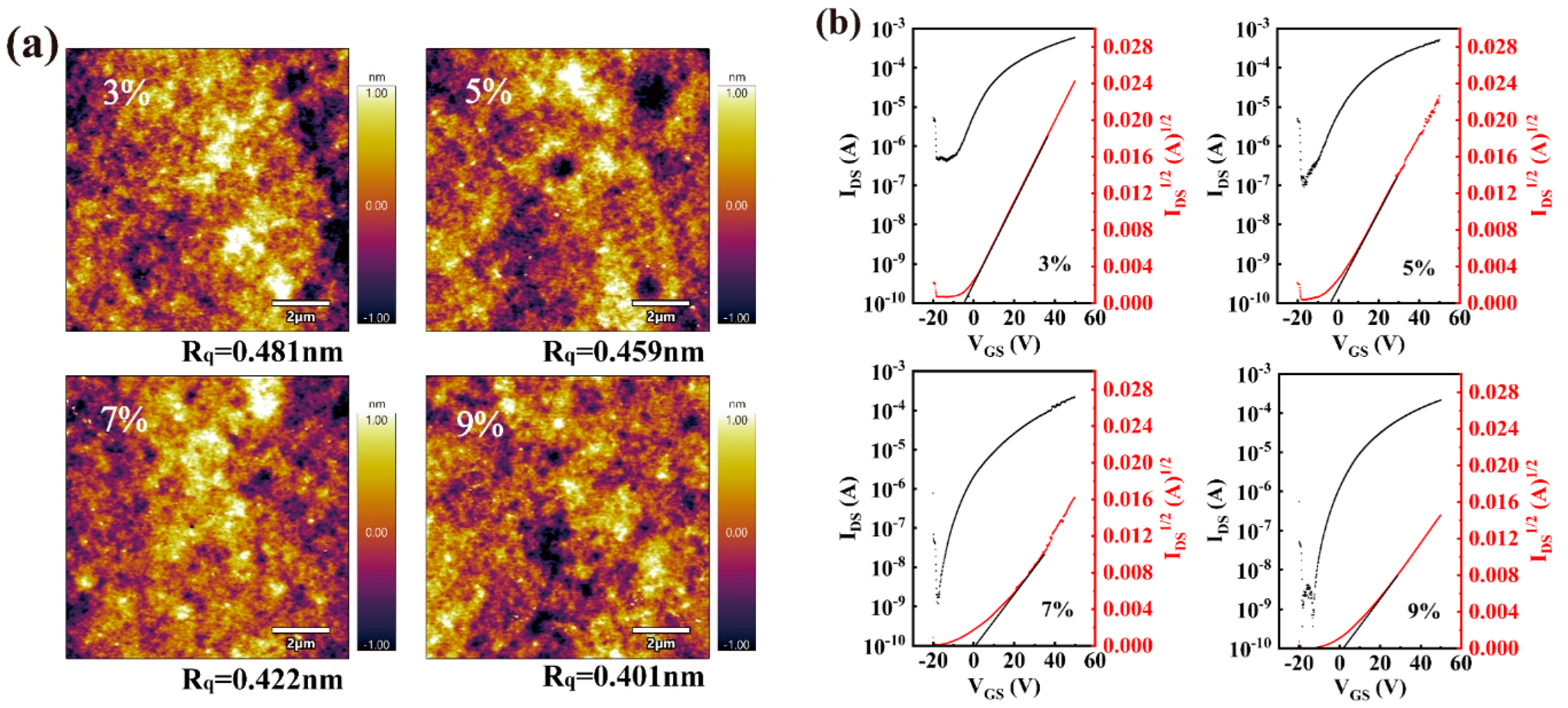
To further optimize the performance of the heterojuction TFTs, we fabricated and investigated In2O3/InGdO TFTs with different Gd doping concentrations. The morphology of the In2O3/InGdO thin films was analyzed for understanding the dependence of the properties of the In2O3/InGdO TFTs on the Gd doping concentration, as shown in Figure 3a. The RMS roughness of the 3%, 5%, 7%, and 9% Gd-doped In2O3/InGdO films were 0.481 nm, 0.459 nm, 0.422 nm and 0.401 nm, respectively. There was no obvious difference in RMS roughness levels of less than 1 nm, illustrating that the samples are smooth and continuous, which is conducive to strengthening their adhesion and forming a good Ohmic contact between the channel layers and Al source/drain electrodes. Next, the In2O3/InGdO TFTs with Gd concentrations increasing from 3% to 5%, 7%, and 9% were fabricated and measured, as indicated in Figure 3b. The results are as follows, with accumulating Gd doping concentration: the mobility decreases evidently from 6.22 to 5.38, 4.34, and 2.54 cm2V−1s−1, and the Vth gradually rises from −4.61 to −3.77, 0.97, and 2.40 V. Because the oxygen vacancy in the channel layer was suppressed by the Gd ions, less oxygen vacancy which remains in the channel layer ultimately induces a lower conductive In2O3/InGdO channel. The improvement of the Ion/Ioff from 1.84 × 10³ to 9.01 × 10³, 3.18 × 10⁵, and 3.71 × 10⁵ is owing to the low Ioff derived from the higher Gd doping concentration in the InGdO layer, and the guaranteed Ion originated from the In2O3 layer thus leads to the increase in Ion/Ioff. Additionally, the SS varies from 8.10 to 7.68, 4.54, and then to 3.18 V/dec, which proves that the SS of devices can be effectively improved by modulating the buffer layer via changing the concentration of Gd doping ions in the heterojunction channel TFTs.
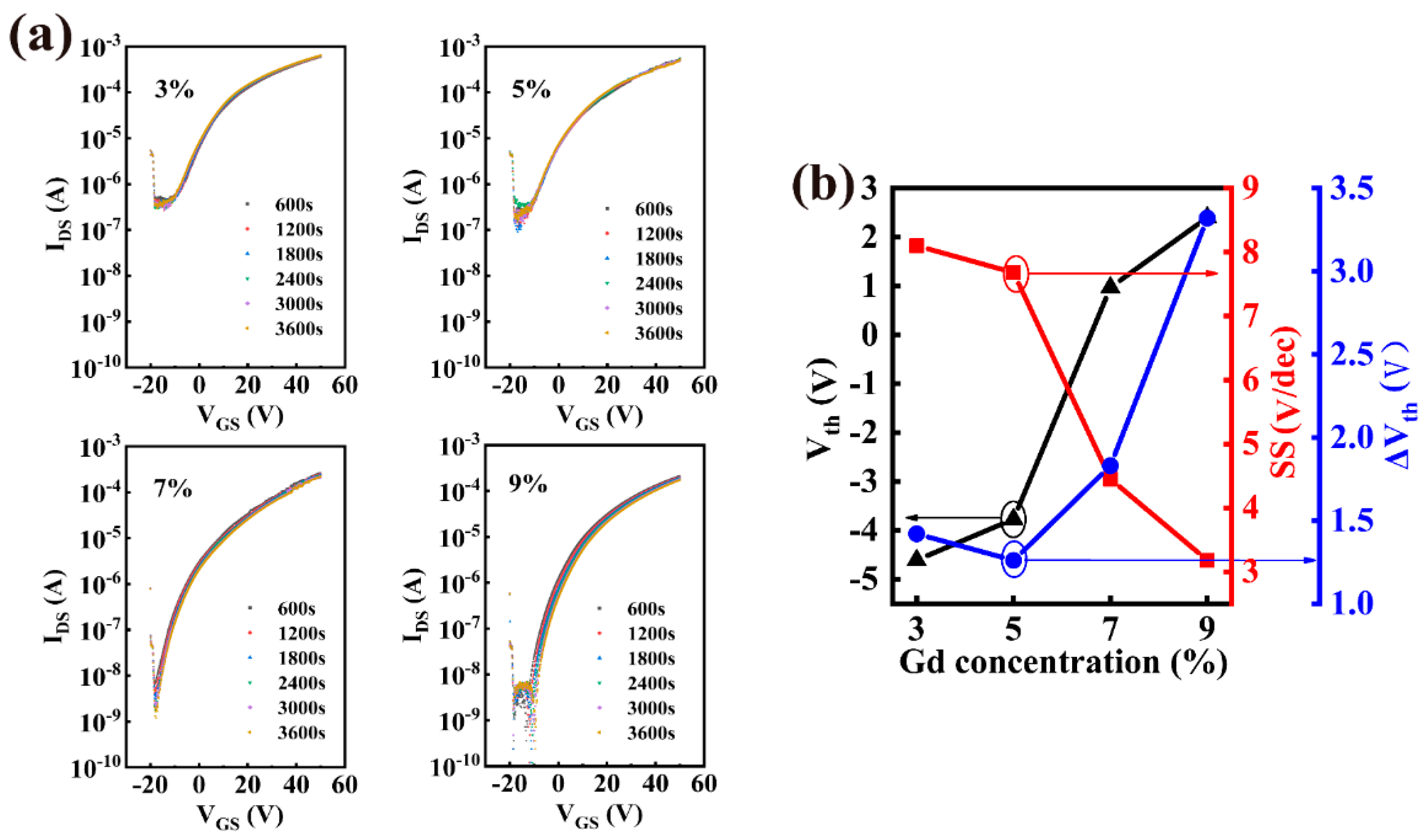
The evolution of the transfer curves of the TFTs under the PBS was studied to further investigate the influence of the Gd doping concentration on the stability of In2O3/InGdO TFTs, as shown in Figure 4a. We found that the ΔVth value decreased slightly when the content of Gd ions increased from 3% to 5%, which is due to fewer oxygen vacancies existing in the channel layer because of the introduction of more Gd ions in higher concentrations of doping samples. The ΔVth value increased again when the content of Gd ions increased from 7% to 9%, and the devices showed a larger ΔVth with stress time. Generally, SS values reflect ΔVth, which is related to the fast bulk traps and the interface trap density between the dielectric and the semiconductor [2,23,37]. Thus, we can speculate that additional trap states are generated at the dielectric/semiconductor interface during PBS of TFTs with highly doped semiconductor films or the fast bulk trap density of the device plays a more dominant role than the interfacial trap density [12]. The variations of Vth, SS and ΔVth are shown in Figure 4b. Additionally, relevant electrical performance parameters are extracted and listed in Table 1. Overall, the In2O3/InGdO TFTs demonstrate optimum electrical performance and stability at 7% Gd content, which has been verified by several of the experiments.
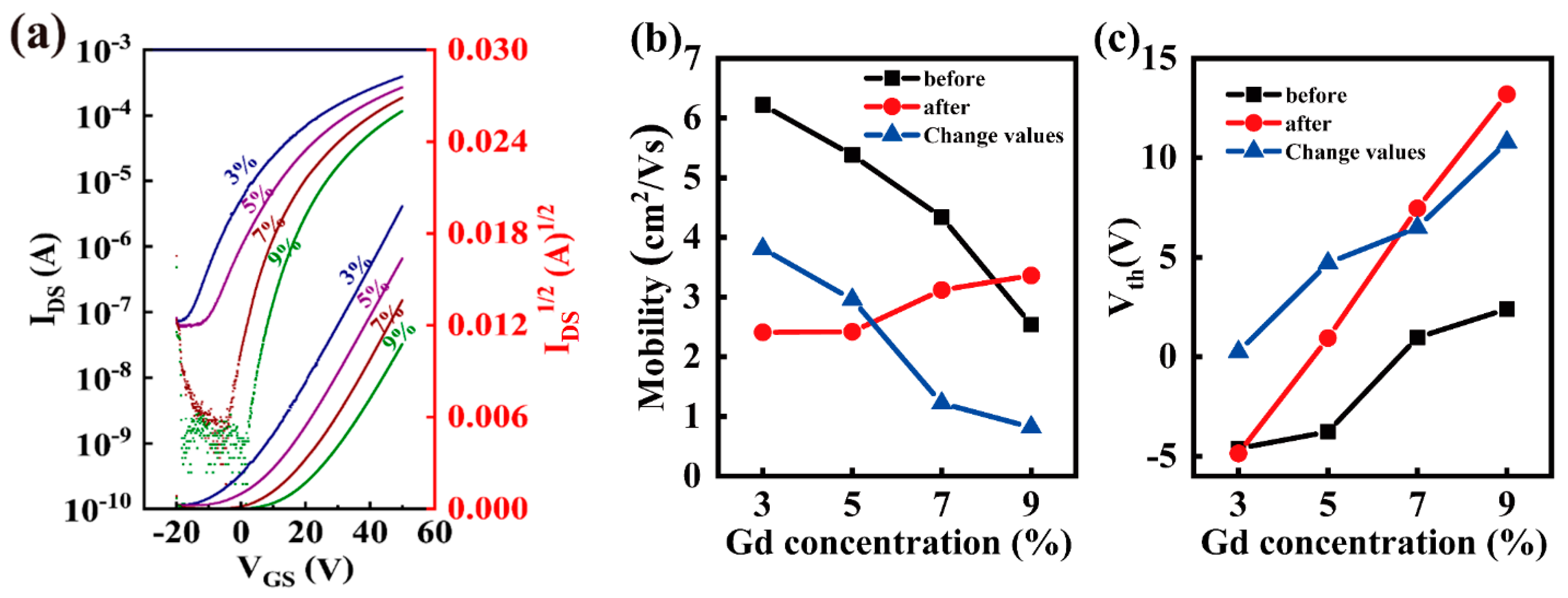
The transfer characteristics as a function of the Gd doping concentration of In2O3/InGdO TFTs after three months are shown in Figure 5a and associated parameters were extracted and listed in Table 2. It was observed that the devices still have relatively favorable electrical performance compared to the initial one, despite having the larger Vth. Aging tests have proven that In2O3/InGdO TFTs can accomplish long-term air stability while maintaining optimal switching property at high mobility. The most intriguing part is that the mobility values of the TFTs increase from 2.41 to 2.42, 3.12, and 3.36 cm2V−1s−1, which is contrary to the increasing doping concentrations from 3% to 5%, 7%, and 9%. Additionally, the Vth values for In2O3/InGdO TFTs changed, with 3%, 5%, 7% and 9% Gd concentrations gradually increased from −4.86 to 0.94, 7.46 and 13.19 V, as shown in Figure 5c. Here, mobility is also associated with a strong increase in Vth. In addition, we found that the mobility values of the TFTs change from 6.22 to 2.41 cm2V−1s−1 for 3% Gd-doped In2O3/InGdO TFT, from 5.38 to 2.42 cm2V−1s−1 for 5% Gd-doped In2O3/InGdO TFT, from 4.34 to 3.12 cm2V−1s−1 for 7% Gd-doped In2O3/InGdO TFTs, and from 2.54 to 3.36 cm2V−1s−1 for 9% Gd-doped In2O3/InGdO TFTs after three months. The corresponding values of the mobility change for In2O3/InGdO TFTs with 3%, 5%, 7% and 9% Gd concentrations gradually diminished from 3.81 to 2.96, 1.22 and 0.82 cm2V−1s−1; the specific trends are shown in Figure 5b. Thereby, we presume that the Gd ions play a key role in inhibiting the aging of the device, although further confirmation is still desirable.

4. Conclusions

In conclusion, we fabricated TFTs with the In2O3/InGdO heterojunction channel layer using a solution process, and compared the electrical properties with single-layer In2O3 TFTs and InGdO TFTs. In our results, the InGdO TFT showed a higher Ion/Ioff of 1.30 × 10⁷, a smaller SS of 1.75 V/dec, and a smaller ΔVth of 0.85 V. Unfortunately, the InGdO TFT achieved a lower mobility of 1.37 cm2V−1s−1 in comparison to the In2O3 TFT. However, the In2O3/InGdO TFT, composed of a highly conductive In2O3 film as the primary transmission layer and a subconductive InGdO film as the buffer layer, showed high electrical performance with higher mobility and higher Ion/Ioff. The results indicate that the high carrier concentration the In2O3 layer close to the insulation layer ensures the excellent mobility of In2O3/InGdO TFTs and low carrier concentration InGdO layer can reduce the Ioff of the devices, thereby increasing the Ion/Ioff of the devices. Furthermore, the PBS test results indicate that TFTs with In2O3/InGdO heterojunction channels are much more stable. In addition, to further optimize the performance of the heterojunction TFTs, the influence of the Gd doping concentration have been thoroughly studied. The results show the 7% Gd-doped In2O3/InGdO TFT has optimum characteristics, displaying a superb mobility of 4.34 cm2V−1s−1, a close-to-0 Vth of 0.97 V, an SS of 4.54 V/dec, a high Ion/Ioff of 3.18 × 10⁵, and a small ΔVth of 1.83 V. Finally, an aging test was carried out after three months, indicating that the In2O3/InGdO TFTs enable long-term air stability while retaining an optimal switching property of high mobility. The work demonstrates that the heterojunction channel structure of solution-processed metal-oxide semiconductors is feasible for fabricating the high performance TFTs, which further explores a broad pathway for the development of high-performance, low-cost, and large-area oxide electronics.

Author Contributions

Conceptualization, X.Z. and S.L.; methodology, P.Z.; validation, G.S. and L.Y.; writing—original draft preparation, S.L.; writing—review and editing, X.Z.; supervision, X.Z.; project administration, X.Z.; funding acquisition, X.Z. All authors have read and agreed to the published version of the manuscript.

Funding

This research was funded by Natural Science Foundation of Henan Province (Grant No. 202300410036), Key research project in University of Henan Province (20A510003) and the National Natural Science Foundation of China (Grant No. U1504625).

Institutional Review Board Statement

Not applicable.

Informed Consent Statement

Not applicable.

Data Availability Statement

All data generated or analyzed during this study are included in this published article.

Conflicts of Interest

The authors declare no conflict of interest.

References

  1. Yu, X.; Zhou, N.; Smith, J.; Lin, H.; Stallings, K.; Yu, J.; Marks, T.J.; Facchetti, A. Synergistic approach to high-performance oxide thin film transistors using a bilayer channel architecture. ACS Appl. Mater. Interfaces 2013, 5, 7983–7988. [Google Scholar] [CrossRef] [PubMed]
  2. Abliz, A.; Huang, C.W.; Wang, J.; Xu, L.; Liao, L.; Xiao, X.; Wu, W.W.; Fan, Z.; Jiang, C.; Li, J.; et al. Rational Design of ZnO:H/ZnO Bilayer Structure for High-Performance Thin-Film Transistors. ACS Appl. Mater. Interfaces 2016, 8, 7862–7868. [Google Scholar] [CrossRef]
  3. Bang, K.; Son, G.-C.; Son, M.; Jun, J.-H.; An, H.; Baik, K.H.; Myoung, J.-M.; Ham, M.-H. Effects of Li doping on the structural and electrical properties of solution-processed ZnO films for high-performance thin-film transistors. J. Alloy. Compd. 2018, 739, 41–46. [Google Scholar] [CrossRef]
  4. Chen, X.; Wan, J.; Wu, H.; Liu, C. ZnO bilayer thin film transistors using H2O and O3 as oxidants by atomic layer deposition. Acta Mater. 2020, 185, 204–210. [Google Scholar] [CrossRef]
  5. Khim, D.; Lin, Y.H.; Nam, S.; Faber, H.; Tetzner, K.; Li, R.; Zhang, Q.; Li, J.; Zhang, X.; Anthopoulos, T.D. Modulation-Doped In2O3/ZnO Heterojunction Transistors Processed from Solution. Adv. Mater. 2017, 29, 1605837. [Google Scholar] [CrossRef]
  6. Zhao, X.; Li, J.; Yang, Y.; Zhu, C.; Huang, J.; Duan, J.; Lu, Y.; Lan, P.; Song, W. Low indium content In–Zn–O system towards transparent conductive films: Structure, properties and comparison with AZO and GZO. J. Mater. Sci. Mater. Electron. 2017, 28, 13297–13302. [Google Scholar] [CrossRef]
  7. Li, H.; Han, D.; Dong, J.; Yu, W.; Liang, Y.; Luo, Z.; Zhang, S.; Zhang, X.; Wang, Y. Enhanced electrical properties of dual-layer channel ZnO thin film transistors prepared by atomic layer deposition. Appl. Surf. Sci. 2018, 439, 632–637. [Google Scholar] [CrossRef]
  8. He, J.; Li, G.; Lv, Y.; Wang, C.; Liu, C.; Li, J.; Flandre, D.; Chen, H.; Guo, T.; Liao, L. Defect Self-Compensation for High-Mobility Bilayer InGaZnO/In2O3 Thin-Film Transistor. Adv. Electron. Mater. 2019, 5, 1900125. [Google Scholar] [CrossRef]
  9. Yuan, Z.; Zhu, X.; Wang, X.; Cai, X.; Zhang, B.; Qiu, D.; Wu, H. Annealing effects of In2O3 thin films on electrical properties and application in thin film transistors. Thin Solid Film. 2011, 519, 3254–3258. [Google Scholar] [CrossRef]
  10. Kim, T.; Jang, B.; Bae, J.-H.; Park, H.; Cho, C.S.; Kwon, H.-J.; Jang, J. Improvement in the Performance of Sol–Gel Processed In2O3Thin-Film Transistor Depending on Sb Dopant Concentration. IEEE Electron. Device Lett. 2017, 38, 1027–1030. [Google Scholar] [CrossRef]
  11. Parthiban, S.; Kwon, J.-Y. Role of dopants as a carrier suppressor and strong oxygen binder in amorphous indium-oxide-based field effect transistor. J. Mater. Res. 2014, 29, 1585–1596. [Google Scholar] [CrossRef]
  12. Jaehnike, F.; Pham, D.V.; Bock, C.; Kunze, U. Role of gallium and yttrium dopants on the stability and performance of solution processed indium oxide thin-film transistors. J. Mater. Chem. C 2019, 7, 7627–7635. [Google Scholar] [CrossRef]
  13. Lee, S.-H.; Kim, T.; Lee, J.; Avis, C.; Jang, J. Solution-processed gadolinium doped indium-oxide thin-film transistors with oxide passivation. Appl. Phys. Lett. 2017, 110, 122102. [Google Scholar] [CrossRef]
  14. Abliz, A.; Xu, L.; Wan, D.; Duan, H.; Wang, J.; Wang, C.; Luo, S.; Liu, C. Effects of yttrium doping on the electrical performances and stability of ZnO thin-film transistors. Appl. Surf. Sci. 2019, 475, 565–570. [Google Scholar] [CrossRef]
  15. Jeon, S.; Kim, S.I.; Park, S.; Song, I.; Park, J.; Kim, S.; Kim, C. Low-Frequency Noise Performance of a Bilayer InZnO–InGaZnO Thin-Film Transistor for Analog Device Applications. IEEE Electron. Device Lett. 2010, 31, 1128–1130. [Google Scholar] [CrossRef]
  16. Li, H.; Han, D.; Liu, L.; Dong, J.; Cui, G.; Zhang, S.; Zhang, X.; Wang, Y. Bi-layer Channel AZO/ZnO Thin Film Transistors Fabricated by Atomic Layer Deposition Technique. Nanoscale Res. Lett. 2017, 12, 223. [Google Scholar] [CrossRef] [PubMed]
  17. Cho, S.W.; Yun, M.G.; Ahn, C.H.; Kim, S.H.; Cho, H.K. Bi-layer channel structure-based oxide thin-film transistors consisting of ZnO and Al-doped ZnO with different Al compositions and stacking sequences. Electron. Mater. Lett. 2015, 11, 198–205. [Google Scholar] [CrossRef]
  18. Xiao, P.; Dong, T.; Lan, L.; Lin, Z.; Song, W.; Song, E.; Sun, S.; Li, Y.; Gao, P.; Luo, D.; et al. High-mobility flexible thin-film transistors with a low-temperature zirconium-doped indium oxide channel layer. Phys. Status Solidi (RRL)-Rapid Res. Lett. 2016, 10, 493–497. [Google Scholar] [CrossRef]
  19. Chauhan, R.N.; Tiwari, N.; Liu, P.-T.; Shieh, H.-P.D.; Kumar, J. Silicon induced stability and mobility of indium zinc oxide based bilayer thin film transistors. Appl. Phys. Lett. 2016, 109, 202107. [Google Scholar] [CrossRef]
  20. Yun, M.G.; Ahn, C.H.; Kim, Y.K.; Cho, S.W.; Cho, H.K.; Kim, H. Effects of top-layer thickness on electrical performance and stability in VZTO/ZTO bi-layer thin-film transistors. J. Alloy. Compd. 2016, 672, 449–456. [Google Scholar] [CrossRef]
  21. Hsu, H.-H.; Chang, C.-Y.; Cheng, C.-H.; Chiou, S.-H.; Huang, C.-H. High Mobility Bilayer Metal–Oxide Thin Film Transistors Using Titanium-Doped InGaZnO. IEEE Electron. Device Lett. 2014, 35, 87–89. [Google Scholar] [CrossRef]
  22. Choi, J.H.; Yang, J.-H.; Nam, S.; Pi, J.-E.; Kim, H.-O.; Kwon, O.-S.; Park, E.-S.; Hwang, C.-S.; Cho, S.H. InZnO/AlSnZnInO Bilayer Oxide Thin-Film Transistors with High Mobility and High Uniformity. IEEE Electron. Device Lett. 2016, 37, 1295–1298. [Google Scholar] [CrossRef]
  23. Seul, H.J.; Kim, M.J.; Yang, H.J.; Cho, M.H.; Cho, M.H.; Song, W.B.; Jeong, J.K. Atomic Layer Deposition Process-Enabled Carrier Mobility Boosting in Field-Effect Transistors through a Nanoscale ZnO/IGO Heterojunction. ACS Appl. Mater. Interfaces 2020, 12, 33887–33898. [Google Scholar] [CrossRef]
  24. Liang, K.; Wang, Y.; Shao, S.; Luo, M.; Pecunia, V.; Shao, L.; Zhao, J.; Chen, Z.; Mo, L.; Cui, Z. High-performance metal-oxide thin-film transistors based on inkjet-printed self-confined bilayer heterojunction channels. J. Mater. Chem. C 2019, 7, 6169–6177. [Google Scholar] [CrossRef]
  25. Lee, H.; Zhang, X.; Kim, J.W.; Kim, E.J.; Park, J. Investigation of the Electrical Characteristics of Bilayer ZnO/In2O3 Thin-Film Transistors Fabricated by Solution Processing. Materials 2018, 11, 2103. [Google Scholar] [CrossRef]
  26. Yue, D.; Guo, S.; Han, S.; Cao, P.; Zeng, Y.; Xu, W.; Fang, M.; Liu, W.; Zhu, D.; Lu, Y.; et al. Facile fabrication of MgZnO/ZnO composites for high performance thin film transistor. J. Alloy. Compd. 2021, 873, 159840. [Google Scholar] [CrossRef]
  27. Nam, S.; Yang, J.-H.; Cho, S.H.; Choi, J.H.; Kwon, O.-S.; Park, E.-S.; Lee, S.-J.; Cho, K.-I.; Jang, J.; Hwang, C.-S. Solution-processed indium-free ZnO/SnO2 bilayer heterostructures as a low-temperature route to high-performance metal oxide thin-film transistors with excellent stabilities. J. Mater. Chem. C 2016, 4, 11298–11304. [Google Scholar] [CrossRef]
  28. Yang, C.P.; Chang, S.J.; Chang, T.H.; Wei, C.Y.; Juan, Y.M.; Chiu, C.J.; Weng, W.Y. Thin-Film Transistors With Amorphous Indium–Gallium-Oxide Bilayer Channel. IEEE Electron. Device Lett. 2017, 38, 572–575. [Google Scholar] [CrossRef]
  29. Lee, W.J.; Choi, J.G.; Sung, S.; Kim, C.H.; Na, S.; Joo, Y.C.; Park, S.; Yoon, M.H. Rapid and Reliable Formation of Highly Densified Bilayer Oxide Dielectrics on Silicon Substrates via DUV Photoactivation for Low-Voltage Solution-Processed Oxide Thin-Film Transistors. ACS Appl. Mater. Interfaces 2021, 13, 2820–2828. [Google Scholar] [CrossRef]
  30. Xu, W.; Zhang, G.; Feng, X. Room temperature fabricated high performance IAZO thin film transistors with dual-active-layer structure and sputtered Ta2O5 gate insulator. J. Alloy. Compd. 2021, 862, 158030. [Google Scholar] [CrossRef]
  31. Huang, W.; Guo, P.; Zeng, L.; Li, R.; Wang, B.; Wang, G.; Zhang, X.; Chang, R.P.H.; Yu, J.; Bedzyk, M.J.; et al. Metal Composition and Polyethylenimine Doping Capacity Effects on Semiconducting Metal Oxide-Polymer Blend Charge Transport. J. Am. Chem. Soc. 2018, 140, 5457–5473. [Google Scholar] [CrossRef] [PubMed]
  32. Seo, J.S.; Bae, B.S. Improved electrical performance and bias stability of solution-processed active bilayer structure of indium zinc oxide based TFT. ACS Appl. Mater. Interfaces 2014, 6, 15335–15343. [Google Scholar] [CrossRef] [PubMed]
  33. Jeong, S.; Ha, Y.G.; Moon, J.; Facchetti, A.; Marks, T.J. Role of gallium doping in dramatically lowering amorphous-oxide processing temperatures for solution-derived indium zinc oxide thin-film transistors. Adv. Mater. 2010, 22, 1346–1350. [Google Scholar] [CrossRef] [PubMed]
  34. Su, J.; Wang, Q.; Ma, Y.; Li, R.; Dai, S.; Wang, Y.; Yang, H.; Zhang, X. Amorphous InZnO:Li/ZnSnO:Li dual-active-layer thin film transistors. Mater. Res. Bull. 2019, 111, 165–169. [Google Scholar] [CrossRef]
  35. Saha, J.K.; Billah, M.M.; Jang, J. Triple-Stack ZnO/AlZnO/YZnO Heterojunction Oxide Thin-Film Transistors by Spray Pyrolysis for High Mobility and Excellent Stability. ACS Appl. Mater. Interfaces 2021, 13, 37350–37362. [Google Scholar] [CrossRef]
  36. Liu, A.; Liu, G.X.; Zhu, H.H.; Xu, F.; Fortunato, E.; Martins, R.; Shan, F.K. Fully solution-processed low-voltage aqueous In2O3 thin-film transistors using an ultrathin ZrOx dielectric. ACS Appl. Mater. Interfaces 2014, 6, 17364–17369. [Google Scholar] [CrossRef]
  37. Cho, M.H.; Choi, C.H.; Seul, H.J.; Cho, H.C.; Jeong, J.K. Achieving a Low-Voltage, High-Mobility IGZO Transistor through an ALD-Derived Bilayer Channel and a Hafnia-Based Gate Dielectric Stack. ACS Appl. Mater. Interfaces 2021, 13, 16628–16640. [Google Scholar] [CrossRef] [PubMed]
Figure 1. Schematic cross-sectional view of (a) the In2O3 or InGdO and (b) the In2O3/InGdO heterojunction TFTs. (c) XRD patterns of the In2O3, InGdO, and In2O3/InGdO thin films annealed at 300 °C. AFM surface morphology of (d) In2O3 (e) InGdO (f) In2O3/InGdO thin films annealed at 300 °C.
Nanomaterials 12 02783 g001
Figure 2. The representative output curves (ac) and transfer curves (df) and transfer curves under the PBS (gi) of the In2O3 or InGdO single-layer and In2O3/InGdO heterojunction TFTs at VDS = 10 V.
Nanomaterials 12 02783 g002
Figure 3. (a) AFM images of surface morphology of the In2O3/InGdO TFTs with different Gd concentrations. (b) Typical transfer curves of the In2O3/InGdO TFTs with different Gd concentrations at VDS = 10 V.
Nanomaterials 12 02783 g003
Figure 4. (a) The evolution of the transfer cures as a function of applied stress time at VDS = 10 V of the In2O3/InGdO TFTs with different Gd concentrations. (b) The volatility of threshold voltage, subthreshold swing and ΔVth of the In2O3/InGdO TFTs with increasing Gd concentrations.
Nanomaterials 12 02783 g004
Figure 5. (a) Transfer curves of the In2O3/InGdO TFTs with different Gd doping concentrations at VDS = 10 V after three months. (b) The fluctuations of mobility of the In2O3/InGdO TFTs with different Gd doping concentrations before and after three months. (c) The fluctuations of Vth of the In2O3/InGdO TFTs with different Gd doping concentrations before and after three months.
Nanomaterials 12 02783 g005
Table 1. Extracted electrical parameters in the In2O3/InGdO TFTs with various Gd doping concentrations.
Gd
Concentration
Saturation Mobility
( c m 2 /V s)
Threshold
Voltage (V)
Subthreshold
Swing (V/dec)
Off-State
Current (A)
On/Off RatioΔVth
(V)
In 2 O 3 / In 2 O 3 : Gd
(3%)
6.22−4.618.103.55 × 10 7 1.84 × 10 3 1.42
In 2 O 3 / In 2 O 3 : Gd
(5%)
5.38−3.777.687.86 × 10 8 9.01 × 10 3 1.26
In 2 O 3 / In 2 O 3 : Gd
(7%)
4.340.974.541.24 × 10 9 3.18 × 10 5 1.83
In 2 O 3 / In 2 O 3 : Gd
(9%)
2.542.403.189.12 × 10 10 3.71 × 10 5 3.32
Table 2. Extracted electrical parameters in the In2O3/InGdO TFTs with various Gd doping concentrations after three months.
Gd
Concentration
Saturation Mobility
( c m 2 /V s)
Threshold Voltage (V)Subthreshold Swing (V/dec)Off-State
Current (A)
On/Off Ratio
In 2 O 3 / In 2 O 3 : Gd
(3%)
2.41−4.868.827.54 × 10 8 8.03 × 10 3
In 2 O 3 / In 2 O 3 : Gd
(5%)
2.420.948.285.76 × 10 8 8.65 × 10 3
In 2 O 3 / In 2 O 3 : Gd
(7%)
3.127.463.931.06 × 10 9 3.44 × 10 5
In 2 O 3 / In 2 O 3 : Gd
(9%)
3.3613.193.402.96 × 10 10 8.38 × 10 5
Publisher’s Note: MDPI stays neutral with regard to jurisdictional claims in published maps and institutional affiliations.