
Tailoring the Hybrid Magnetron Sputtering Process (HiPIMS and dcMS) to Manufacture Ceramic Multilayers: Powering Conditions, Target Materials, and Base Layers

 , ,
, ,  ,
,  , ,
, ,  ,
,  ,
, 
Abstract
:1. Introduction
2. Materials and Methods
2.1. Coating Deposition
2.2. Coating Characterization
3. Results and Discussion
4. Conclusions
Author Contributions
Funding
Data Availability Statement
Acknowledgments
Conflicts of Interest
References
- Cavaleiro, A.; de Hosson, J.T.M. Nanostructured Coatings, 1st ed.; Springer: New York, NY, USA, 2006; ISBN 978-0-387-25642-9. [Google Scholar]
- Holmberg, K.; Mathews, A. Coatings Tribology: Properties, Mechanisms, Techniques and Applications in Surface Engineering, 2nd ed.; Elsevier Science: Amsterdam, The Netherlands, 2009. [Google Scholar]
- Guimarães, M.C.R.; de Castilho, B.C.N.M.; Cunha, C.; Correr, W.R.; Mordente, P.; Alvarez, F.; Pinto, H.C. On the Effect of Aluminum on the Microstructure and Mechanical Properties of CrN Coatings Deposited by HiPIMS. Mater. Res. 2018, 21, 1–6. [Google Scholar] [CrossRef]
- Guimaraes, M.C.R.; de Castilho, B.C.N.M.; de Souza Nossa, T.; Avila, P.R.T.; Cucatti, S.; Alvarez, F.; Garcia, J.L.; Pinto, H.C. On the Effect of Substrate Oscillation on CrN Coatings Deposited by HiPIMS and DcMS. Surf. Coat. Technol. 2018, 340, 112–120. [Google Scholar] [CrossRef]
- Steyer, P.; Mendibide, C.; Millet, J.-P.; Mazille, H. Improvement of High Temperature Corrosion Resistance of Tool Steels by Nanostructured PVD Coatings. Mater. Sci. Forum 2003, 426–432, 2503–2508. [Google Scholar] [CrossRef]
- Brizuela, M.; Garcia-Luis, A.; Braceras, I.; Oñate, J.I.; Sánchez-López, J.C.; Martínez-Martínez, D.; López-Cartes, C.; Fernández, A. Magnetron Sputtering of Cr(Al)N Coatings: Mechanical and Tribological Study. Surf. Coat. Technol. 2005, 200, 192–197. [Google Scholar] [CrossRef]
- Bobzin, K.; Lugscheider, E.; Nickel, R.; Bagcivan, N.; Krämer, A. Wear Behavior of Cr1-XAlxN PVD-Coatings in Dry Running Conditions. Wear 2007, 263, 1274–1280. [Google Scholar] [CrossRef]
- Chim, Y.C.; Ding, X.Z.; Zeng, X.T.; Zhang, S. Oxidation Resistance of TiN, CrN, TiAlN and CrAlN Coatings Deposited by Lateral Rotating Cathode Arc. Thin Solid Film. 2009, 517, 4845–4849. [Google Scholar] [CrossRef]
- Bunshah, F.R. Handbook of Deposition Technologies for Films and Coatings: Science, Applications and Technology, 2nd ed.; William Andrew: Norwich, NY, USA, 1994; ISBN 9780815517467. [Google Scholar]
- Helmersson, U.; Lattemann, M.; Bohlmark, J.; Ehiasarian, A.P.; Gudmundsson, J.T. Ionized Physical Vapor Deposition (IPVD): A Review of Technology and Applications. Thin Solid Film. 2006, 513, 1–24. [Google Scholar] [CrossRef] [Green Version]
- Martin, P.M. Handbook of Deposition Technologies for Films and Coatings: Science, Applications and Technology, 3rd ed.; Elsevier Science: Amsterdam, The Netherlands, 2009; ISBN 9780815520320. [Google Scholar]
- Kelly, P.J.; Arnell, R.D. Magnetron Sputtering: A Review of Recent Developments and Applications. Vacuum 2000, 56, 159–172. [Google Scholar] [CrossRef]
- Kouznetsov, V.; MacÁk, K.; Schneider, J.M.; Helmersson, U.; Petrov, I. A Novel Pulsed Magnetron Sputter Technique Utilizing Very High Target Power Densities. Surf. Coat. Technol. 1999, 122, 290–293. [Google Scholar] [CrossRef]
- Alami, J.; Bolz, S.; Sarakinos, K. High Power Pulsed Magnetron Sputtering: Fundamentals and Applications. J. Alloy. Compd. 2009, 483, 530–534. [Google Scholar] [CrossRef]
- Sarakinos, K.; Alami, J.; Konstantinidis, S. High Power Pulsed Magnetron Sputtering: A Review on Scientific and Engineering State of the Art. Surf. Coat. Technol. 2010, 204, 1661–1684. [Google Scholar] [CrossRef]
- Samuelsson, M.; Lundin, D.; Sarakinos, K.; Björefors, F.; Wälivaara, B.; Ljungcrantz, H.; Helmersson, U. Influence of Ionization Degree on Film Properties When Using High Power Impulse Magnetron Sputtering. J. Vac. Sci. Technol. A Vac. Surf. Film. 2012, 30, 031507. [Google Scholar] [CrossRef] [Green Version]
- de Castilho, B.C.N.M.; Rodrigues, A.M.; Avila, P.R.T.; Apolinario, R.C.; de Souza Nossa, T.; Walczak, M.; Fernandes, J.V.; Menezes, R.R.; de Araújo Neves, G.; Pinto, H.C. Hybrid Magnetron Sputtering of Ceramic Superlattices for Application in a next Generation of Combustion Engines. Sci. Rep. 2022, 12, 2342. [Google Scholar] [CrossRef]
- Greczynski, G.; Lu, J.; Johansson, M.P.; Jensen, J.; Petrov, I.; Greene, J.E.; Hultman, L. Role of Ti N+ and Al N+ Ion Irradiation (N=1, 2) during Ti 1-XAl XN Alloy Film Growth in a Hybrid HIPIMS/Magnetron Mode. Surf. Coat. Technol. 2012, 206, 4202–4211. [Google Scholar] [CrossRef] [Green Version]
- del Giudice, L.; Adjam, S.; la Grange, D.; Banakh, O.; Karimi, A.; Sanjinés, R. NbTiN Thin Films Deposited by Hybrid HiPIMS/DC Magnetron Co-Sputtering. Surf. Coat. Technol. 2016, 295, 99–106. [Google Scholar] [CrossRef]
- Evaristo, M.; Fernandes, F.; Cavaleiro, A. Room and High Temperature Tribological Behaviour of W-DLC Coatings Produced by DCMS and Hybrid DCMS-HiPIMS Configuration. Coatings 2020, 10, 319. [Google Scholar] [CrossRef] [Green Version]
- Hauk, V. Structural and Residual Stress Analysis by Nondestructive Methods; Elsevier: Amsterdam, The Netherlands, 1997. [Google Scholar]
- Paufler, P. Landoldt-Börnstein New Series, Group III; Hellwege, K.H., Ed.; Springer: Berlin/Heidelberg, Germany, 1979; Volume 11. [Google Scholar]
- Oliver, W.C.; Pharr, G.M. An Improved Technique for Determining Hardness and Elastic Modulus Using Load and Displacement Sensing Indentation Experiments. J. Mater. Res. 1992, 7, 1564–1583. [Google Scholar] [CrossRef]
- Bruno, R.A.; Rabello, R.B.; Silva, D.A.; Araujo, J.A. DLC coated ring pack for heavy duty diesel engines. In Blucher Engineering Proceedings; Editora Blucher: São Paulo, Brazil, 2017; pp. 462–476. [Google Scholar]
- Avila, P.R.T.; Apolinário, R.C.; Rodrigues, A.M.; Fernandes, J.V.; Menezes, R.R.; de Araújo Neves, G.; Pinto, H.C. On Improving Wear Resistance of Cr-Al-N Coatings Using Dynamic Glancing Angle DC Magnetron Sputtering. Nanomaterials 2021, 11, 2187. [Google Scholar] [CrossRef]
- Avila, P.R.T.; da Silva, E.P.; Rodrigues, A.M.; Aristizabal, K.; Pineda, F.; Coelho, R.S.; Garcia, J.L.; Soldera, F.; Walczak, M.; Pinto, H.C. On Manufacturing Multilayer-like Nanostructures Using Misorientation Gradients in PVD Films. Sci. Rep. 2019, 9, 15898. [Google Scholar] [CrossRef] [Green Version]
- Avila, P.R.T.; Rodrigues, A.M.; Guimarães, M.C.R.; Walczak, M.; Menezes, R.R.; de Araújo Neves, G.; Pinto, H.C. Nitrogen-Enriched Cr1−xAlxN Multilayer-Like Coatings Manufactured by Dynamic Glancing Angle Direct Current Magnetron Sputtering. Materials 2020, 13, 3650. [Google Scholar] [CrossRef]
- Anders, A. A Structure Zone Diagram Including Plasma-Based Deposition and Ion Etching. Thin Solid Film. 2010, 518, 4087–4090. [Google Scholar] [CrossRef] [Green Version]
- Vetter, J.; Eriksson, A.O.; Reiter, A.; Derflinger, V.; Kalss, W. Quo Vadis: AlCr-Based Coatings in Industrial Applications. Coatings 2021, 11, 344. [Google Scholar] [CrossRef]
- Musil, J.; Kunc, F.; Zeman, H.; Poláková, H. Relationships between Hardness, Young’s Modulus and Elastic Recovery in Hard Nanocomposite Coatings. Surf. Coat. Technol. 2002, 154, 304–313. [Google Scholar] [CrossRef]
- Tsui, T.Y.; Pharr, G.M.; Oliver, W.C.; Bhatia, C.S.; White, R.L.; Anders, S.; Anders, A.; Brown, I.G. Nanoindentation and Nanoscratching of Hard Carbon Coatings for Magnetic Disks. MRS Proc. 1995, 383, 447. [Google Scholar] [CrossRef] [Green Version]


| Sample Name | M01 | M02 | M03 | |
|---|---|---|---|---|
| Chamber pressure | 2.67 × 10⁻¹ Pa | |||
| Bias | −120 V | |||
| Carousel Speed | 1.0 rpm | |||
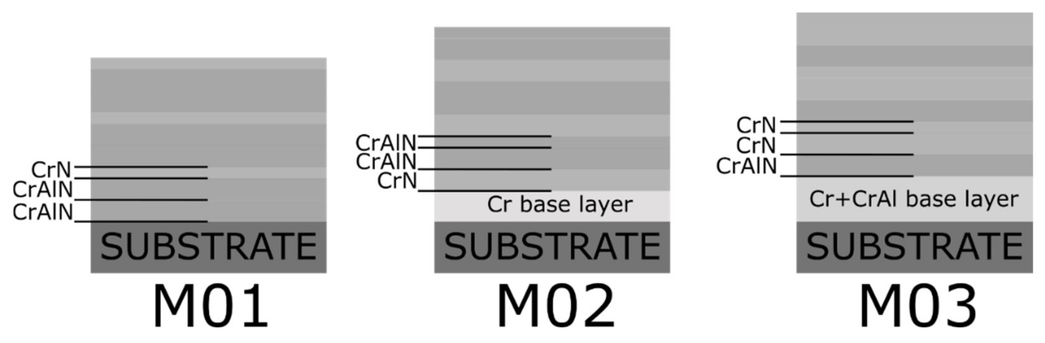
| Base Layer | None | Cr | Cr + CrAl | |
| Base Layer Deposition Time | 2 h | |||
| Target (Base layer) | None | Cr HiPIMS | Same as coating | |
| Atmosphere (Base layer) | Ar (40 sccm) | |||
| Atmosphere (Coating) | Ar (40 sccm) and N2 (50 sccm) | |||
| Target (Coating) | HiPIMS | Cr | CrAl | Cr |
| DC | CrAl | CrAl | Cr | |
| DC | CrAl | Cr | CrAl | |
| M01 | M02 | M03 | ||
|---|---|---|---|---|
| Thickness [μm] | Total | 11.4 ± 0.3 | 11.3 ± 0.1 | 14.9 ± 0.2 |
| Deposition Rate [µm/h] | Base layer | - | 0.35 | 1.2 |
| Coating | 0.57 | 0.53 | 0.63 | |
| Periodicity [nm] | Estimated | 9.5 | 8.7 | 10.5 |
| Calculated by X-ray | 7.1 | 7.7 | - | |
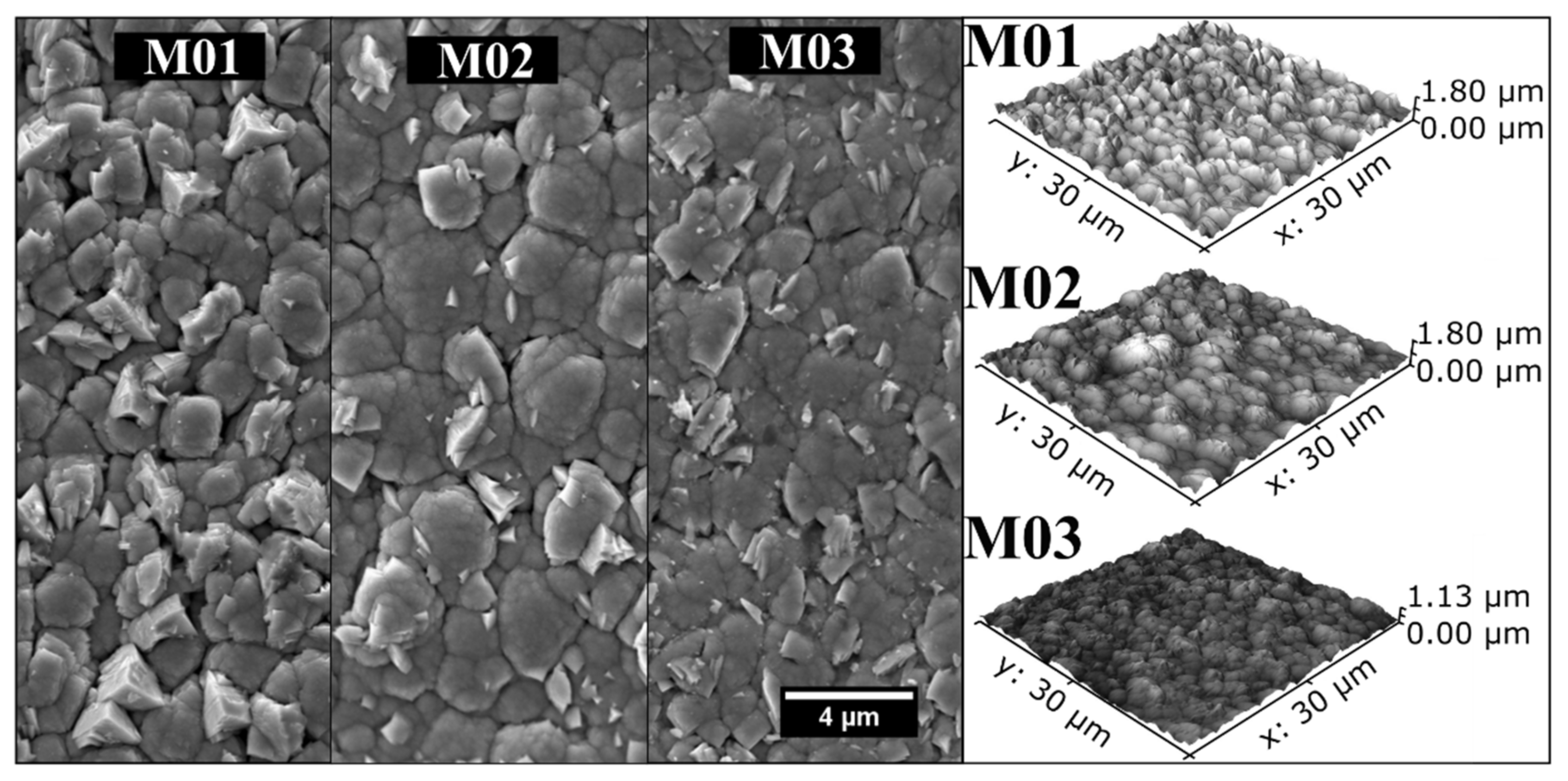
| Roughness [nm] | Ra | 187 | 183 | 120 |
Publisher’s Note: MDPI stays neutral with regard to jurisdictional claims in published maps and institutional affiliations. |
© 2022 by the authors. Licensee MDPI, Basel, Switzerland. This article is an open access article distributed under the terms and conditions of the Creative Commons Attribution (CC BY) license (https://creativecommons.org/licenses/by/4.0/).
Share and Cite
de Castilho, B.C.N.M.; de Sousa Mazuco, F.; Rodrigues, A.M.; Avila, P.R.T.; Apolinario, R.C.; Daum, P.; da Costa, F.P.; Menezes, R.R.; de Araújo Neves, G.; Greiner, C.; et al. Tailoring the Hybrid Magnetron Sputtering Process (HiPIMS and dcMS) to Manufacture Ceramic Multilayers: Powering Conditions, Target Materials, and Base Layers. Nanomaterials 2022, 12, 2465. https://doi.org/10.3390/nano12142465
de Castilho BCNM, de Sousa Mazuco F, Rodrigues AM, Avila PRT, Apolinario RC, Daum P, da Costa FP, Menezes RR, de Araújo Neves G, Greiner C, et al. Tailoring the Hybrid Magnetron Sputtering Process (HiPIMS and dcMS) to Manufacture Ceramic Multilayers: Powering Conditions, Target Materials, and Base Layers. Nanomaterials. 2022; 12(14):2465. https://doi.org/10.3390/nano12142465
Chicago/Turabian Stylede Castilho, Bruno César Noronha Marques, Felipe de Sousa Mazuco, Alisson Mendes Rodrigues, Pedro Renato Tavares Avila, Raira Chefer Apolinario, Philipp Daum, Fabiana Pereira da Costa, Romualdo Rodrigues Menezes, Gelmires de Araújo Neves, Christian Greiner, and et al. 2022. "Tailoring the Hybrid Magnetron Sputtering Process (HiPIMS and dcMS) to Manufacture Ceramic Multilayers: Powering Conditions, Target Materials, and Base Layers" Nanomaterials 12, no. 14: 2465. https://doi.org/10.3390/nano12142465
APA Stylede Castilho, B. C. N. M., de Sousa Mazuco, F., Rodrigues, A. M., Avila, P. R. T., Apolinario, R. C., Daum, P., da Costa, F. P., Menezes, R. R., de Araújo Neves, G., Greiner, C., & Pinto, H. C. (2022). Tailoring the Hybrid Magnetron Sputtering Process (HiPIMS and dcMS) to Manufacture Ceramic Multilayers: Powering Conditions, Target Materials, and Base Layers. Nanomaterials, 12(14), 2465. https://doi.org/10.3390/nano12142465