1. Introduction
In recent years, the instrumented indentation test has gained massive popularity to determine the mechanical behavior of different materials due to its straightforward and standardized experimental procedure. The method requires only a small volume of material for measurement, minimal specimen preparation, and low costs, at the same time enabling the evaluation of the indentation by considering both the force and the displacement during plastic and elastic deformation [
1]. By monitoring the complete loading cycle of increasing and removing the test force, a wide range of mechanical properties, such as the Martens hardness (
Ms), the indentation hardness (
HIT), the indentation modulus (
EIT), the plane strain modulus (
E*), the indentation creep (
CIT), the indentation relaxation (
RIT), and the elasto-plastic behavior (work,
W), can be determined in one measurement [
1]. Based on the measurement results, it is possible to construct stress–strain diagrams, which are of great importance for materials and coatings for which the conventional static tensile test is not applicable. In addition to the above-mentioned mechanical properties, by applying higher loads, it is possible to estimate the indentation fracture toughness of the material based on the cracks at the tips of the Vickers indent.
These mechanical quantities are calculated based on the indenter’s contact (projected) area. Crucial differences can arise when comparing the actual contact area with the area calculated assuming an ideal indenter geometry, particularly at small, measured indentation depths. These differences occur due to the rounding and wear of the indenter’s tip following use. For that reason, it is necessary to determine the actual indenter’s contact surface (area) and use it to calculate the material parameters, ensuring the accuracy and repeatability of the measured values. An indirect way to determine the actual contact area is periodical calibration by utilizing indentations into a material of certified indentation modulus and Poisson’s ratio, known as the reference material [
1].
The reference materials known as the reference blocks are specially produced to assure the structure’s necessary homogeneity, uniformity, and long-term stability. In that way, the homogeneity of mechanical properties is confirmed. Stable temperature and humidity properties, as well as an amorphous molecular structure and an almost pure homogenous microstructure, established the position of the fused silica glass as the most investigated/most used reference material for instrumented indentation tests. Since it has a relatively low modulus of elasticity and Poisson’s ratio, fused silica is supremely brittle. According to the calibration certificate, it is not recommended to perform indentations over 100 mN using the Berkovich or Vickers indenter due to cracks that may influence the results. During this research, the indentation forces were increased to initiate a crack on the corner of Vickers indentations.
The crack shapes appearing in brittle materials are related to the indenter shape and to the nature of the material [
2]. According to Lee et al. [
3], there are five major crack types formed after unloading the sample: radial, lateral, median, half-penny, and Hertzian cone cracks [
2]. Independently of the indenter’s geometry (sharp Vickers or Berkovich, spherical, flat punch), similar crack patterns can be observed in fused silica, with the preferential mode being a cone crack or other types of median-radial cracking [
4]. The initiation of the cone crack is formed on the specimen surface outside the contact zone of the indenter and the fused silica specimen. The propagation of the cone crack has the incline angle,
, in a range from 30°, as reported by Hagan [
5], to 45°, as reported by Michel et al. [
6]. In addition, it has also been established that the incline angle depends mainly on the Poisson’s ratio [
7].
Hagan [
5] concluded that the cone-crack formation is driven only by the elastic stress during the indentation, and the initiation ring is formed only due to positive (tensile) radial stress outside the contact region [
8]. One of the indentation fracture theories presented by Lawn and Evans [
9] indicates that medial (radial, half-penny) cracks are driven by the stress nucleation caused by material flaws under the indenter, and that a flaw has to have a finite size to initiate a median crack. These conclusions are compared with our numerical modeling in the following sections.
Currently, for the modeling of the indentation crack nucleation and propagation, the most used numerical approach is the cohesive zone modeling (CZM). Bruns et al. [
2] modeled the cracking of fused silica under the Berkovich indenter. The authors proposed using the Drucker-Prager Cap plasticity model, which is able to reproduce elasto-plastic material behavior and the hardening due to material densification. Lee et al. [
3] also used CZM to analyze the cracking of a brittle material under a four-sided pyramid (Vickers indenter). The biggest drawback of CZM is that the crack nucleation and propagation directions have to be determined a priori: cracking appears only in the a priori defined cohesive planes. This makes CZM suitable only for capturing the radial or half-penny cracks, but not the cone cracks, which are not planar. Among other possible approaches, the extended finite element method (XFEM) [
10] and the peridynamics [
11] have been attempted. Although both methods are capable of reproducing complex crack patterns, their usage in 3D modeling is still a daunting task, because they tend to become extremely complex due to problems associated with the crack tracking in XFEM, or a proper definition of internal forces and efficient numerical implementation in peridynamics.
The phase-field (PF) method seems to be an appropriate approach to overcome the latter problems. It does not require ad hoc criteria for the nucleation, propagation, or branching of cracks, and its numerical implementation in the existing FEM codes is relatively simple and straightforward. However, due to high computational costs, mainly caused by the need to use very dense meshes in the regions where damage appears, only 2D models have so far been proposed. In general, it has been shown that one of the main problems in phase-field modeling of the indentation process is accurate modeling of crack initiation in an otherwise defect-free material. Additional considerable problems include the proper definition of the length scale parameter value or the definition of the crack driving force. Strobl and Seeling [
8] proposed a 2D phase-field brittle formulation for the simulation of cone-crack formation under the flat indenter. They have studied various modifications of standard AT1 and AT2 models, which render the phase-field method more suitable for indentation simulations. In doing so, they identified the most important problems and proposed certain conditions that have to be fulfilled by the brittle phase-field models in indentation simulations, such as: using appropriate energy decompositions and crack driving functions to account for the tension-compression behavior and crack boundary conditions, using small length scale parameter values in comparison to characteristic crack dimensions to ensure the accurate capture of crack initiation, defining appropriate degradation functions that prevent erroneous phase-field evolution and ensure the linear response before the initiation of damage, and incorporating the material’s tensile strength and fracture toughness as independent material parameters. In their work, they utilized a hybrid approach, where no split is used for the Cauchy stress tensor because the cracks remain opened during the indentation, while the directional split proposed by Steinke and Kaliske [
12] is used for the crack driving function to avoid the crack evolution being driven by a compression stress state. Thereby, the crack driving function itself is formulated by using positive principal stresses as it is deemed more appropriate than by using strains. Small values of length parameters had to be used to capture the spontaneous crack initiation, leading to restrictions on the minimal values of the tension strength in their AT2 model. Fourth-order degradation functions were used to ensure the linear elastic response prior to the onset of damage, but such choice compromises the crack propagation to the fully broken state. The overestimation of the surface crack energy, caused by an over-smearing of the phase-field if a relatively large value of length parameter is used, is avoided by a recalibration of the length parameter and yield functions. The irreversibility of the phase-field is ensured by employing the “crack-like” constraint, allowing for irreversibility of the damage before the onset of a well-defined crack. However, such approach does not work well for all simulation setups. Despite all mentioned restrictions, for a certain choice of input variables for which all required conditions are satisfied, their modified model was able to reproduce the main features of cone-crack initiation and propagation: the formation of the initiation ring around the indenter, a vertical crack propagation, and the conical crack propagation with an inclination to the sample surface. Kindrachuk and Klunker [
13] used a similar brittle phase-field formulation for the axis-symmetric 2D simulation of spherical indentation to investigate a kinked cone-crack propagation, caused by the changing contact conditions between the propagating spherical indenter and the sample surface. They performed a frictionless contact analysis by employing an ad-hoc crack driving force based on the strain measure, similar to the Beltrami criterion of failure, instead of a stress-based crack driving force. The irreversibility was enforced in a “damage-like” manner by employing a history variable. Only one problem setup was analyzed, and the applicability of the method was not studied in detail. In a very recent work, Wu et al. [
14] used an axis-symmetric phase-field cohesive zone model to investigate the flat punch indentation of a homogeneous material with borosilicate glass properties. Therein, the cohesive zone model has been applied to correctly capture the crack nucleation in the otherwise defect-free material. Here, the failure strength can be chosen independently from the fracture toughness by applying the Wu-Nguyen phase-field model for quasi-brittle fracture, where the length parameter is introduced as an independent parameter. This allows for the choice of the length parameter value that is small enough to accurately capture the crack initiation and to prevent the unphysical widening of the damaged zone during the crack propagation. That approach shows impressive potential for correctly capturing all important details of the cracking process caused by the indentation, including the initiation. However, its implementation is more complex than the phase-field models based on the AT2 model, as it requires special solvers for the imposition of the irreversibility condition on the phase-field.
In comparison to the similar phase-field models for the indentation problem, encountered in the available literature, the novelties of the present work are:
To the authors’ knowledge, the present paper represents the first 3D phase-field model of the Vickers indentation fracture to this date.
An asymmetric model, where the energy decomposition is applied for both the crack driving force and the stress field, is used.
Contact analysis with friction is applied.
The proposed numerical model is validated by experimental indentation, showing that the formation of a cone crack is accurately predicted by the current model in the Vickers indentation.
The paper is organized as follows. The experimental setup is presented in
Section 2. Afterwards, the most important details of the used phase-field formulation are exposed, along with the energy decomposition, which has a significant influence on the indentation modeling. Then, the numerical model is described in detail. In
Section 3, the obtained numerical results are compared with the experimental data. Finally, some conclusions are presented in
Section 4.
3. Results and Discussion
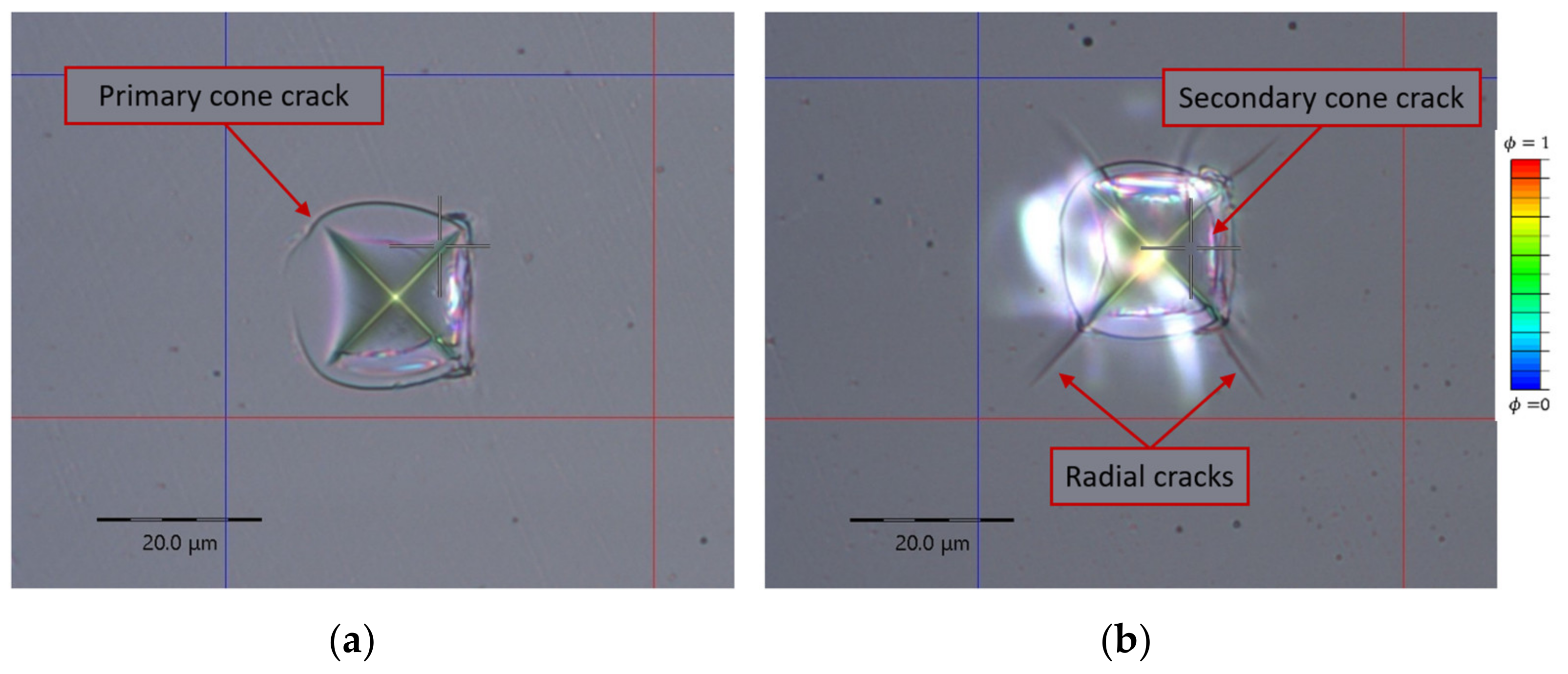
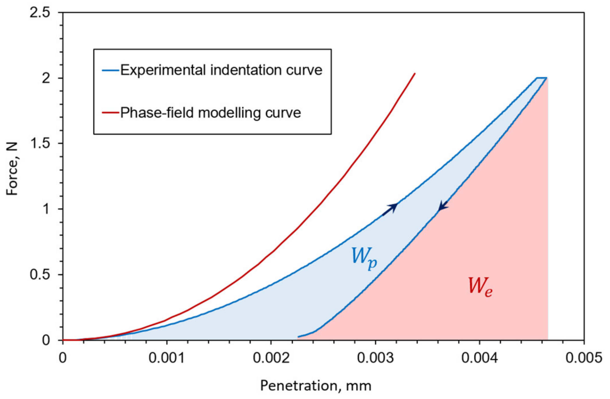
The experimental measurements clearly demonstrate the occurrence of a significant plastic deformation during the Vickers indentation. It is visible as a residual indent after unloading (
Figure 2) and the residual plastic energy in
Figure 1. Even though the elasto-plastic deformation has been detected by other authors, such as in [
2], as an important phenomenon during the Vickers indentation of fused silica, here we applied a brittle phase-field formulation due to the high costs of the phase-field simulations and a complex coupling of damage and plasticity phenomena in the phase-field models. It can be seen from the indentation curve comparison (
Figure 1) that the numerical, brittle formulation, can describe the experimental indentation loading curve relatively well, although with a significantly stiffer response caused by the lack of plastic deformation. Therefore, the implementation of a plastic material model will be in the focus of future research since the authors believe that an adaptive elasto-plastic phase-field formulation is a well-suited approach to model the complex Vickers indentation.
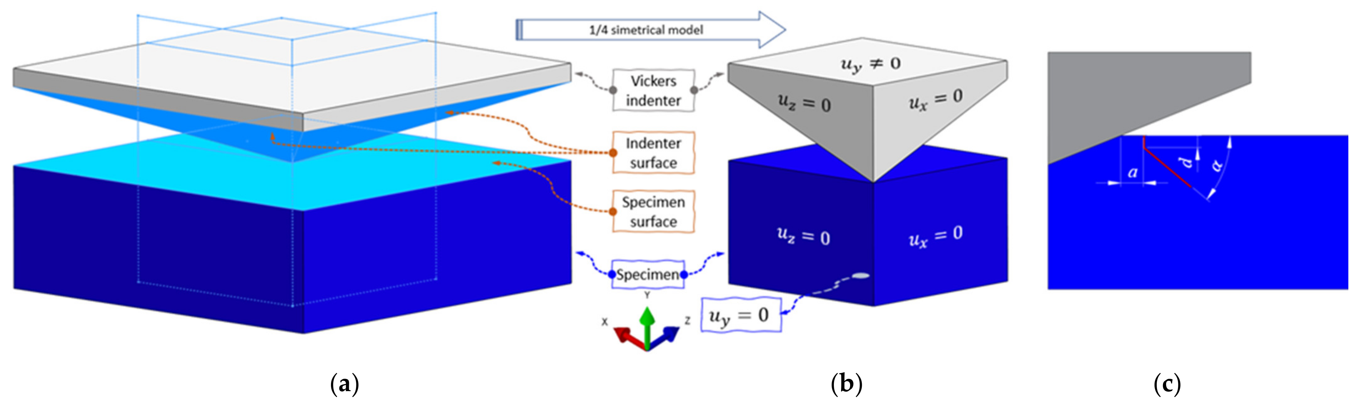
Since the presented phase-field formulation is implemented in the commercial FE software ABAQUS, the use of all interaction features is possible. In this model, the contact interaction is prescribed on the contact surfaces, as described in a later section.
The use of other contact parameters did not afford good results, such as small sliding contact formulation or the penalty contact method. Investigation has shown that the indentation curve did not change (quantitatively) in comparison with the final contact modeling (finite sliding and the Lagrange formulation), but the formation of the cracks, i.e., the growth of the scalar phase-field parameter on the surface, did change. Cracks form in the early stages of the loading process and below the indenter itself. The small sliding contact does not allow the motion of the nodes of adjacent surfaces when the contact is established. This means that the slave nodes stick to the master surface as soon as the contact is established. With the progress of the loading process, they stay stuck to the master surface, unlike the finite sliding formulation, which allows the motion of the nodes in the contact.
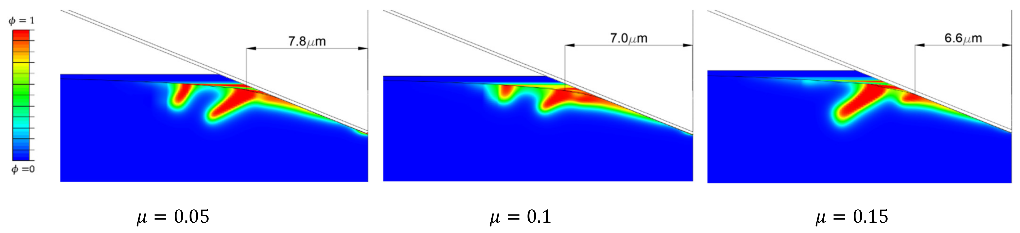
Friction between the indenter surface and the specimen surface is also an influential parameter (
Figure 6). As friction increases, the initial ring forms closer to the indenter centerline. Moreover, the initiation ring of the secondary cone crack (
Figure 2b) propagates deeper as friction decreases.
Unlike Strobl and Seelig [
8], who concluded that the energy decomposition proposed by Freddi cannot replicate the cone crack under the flat indenter with their 2D phase-field formulation, it was shown here that it is possible to model the cone crack with the Vickers indenter by our 3D formulation employing the above-proposed Freddi decomposition.
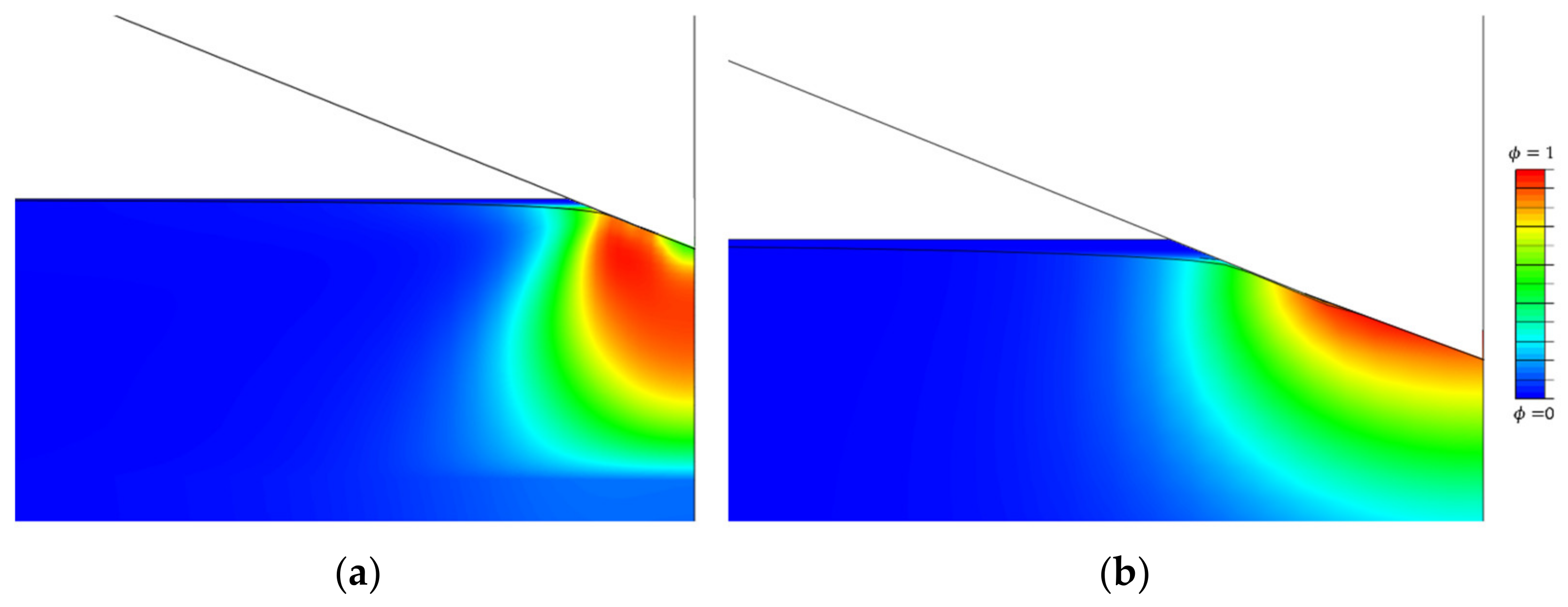
At the beginning of the loading phase, as soon as the contact is established, the phase-field starts to rise slowly. Since the Freddi energy decomposition is introduced, the negative compression stress does not influence the crack initiation. Only after the indenter notably penetrates the specimen does the phase-field start to intensely rise. The formation of the damage below the indenter is not noticed, unlike in the model with the Miehe energy decomposition (
Figure 3).
As reported by Strobl and Seelig [
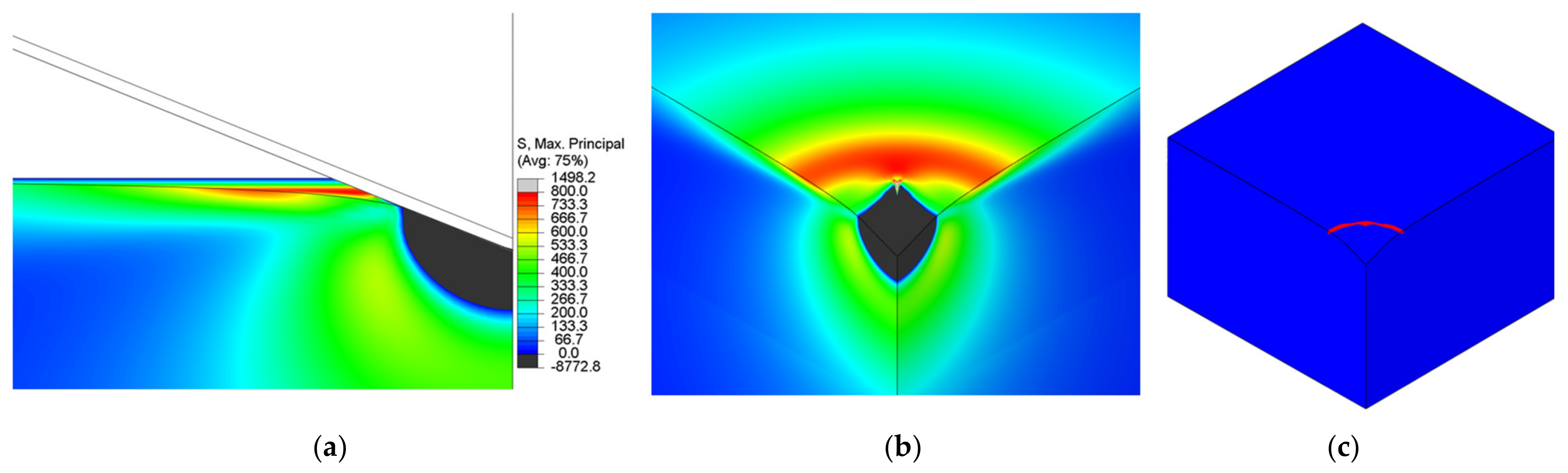
8], the tensile stress on the specimen surface is responsible for the cone-crack initiation. It is visible that the initiation is governed by a weak surface-positive stress field (
Figure 7a,b) that forms crack initiation in the shape of a ring. The initiation ring (
Figure 7) is located outside the contact region at a certain distance from the indenter contact edge.
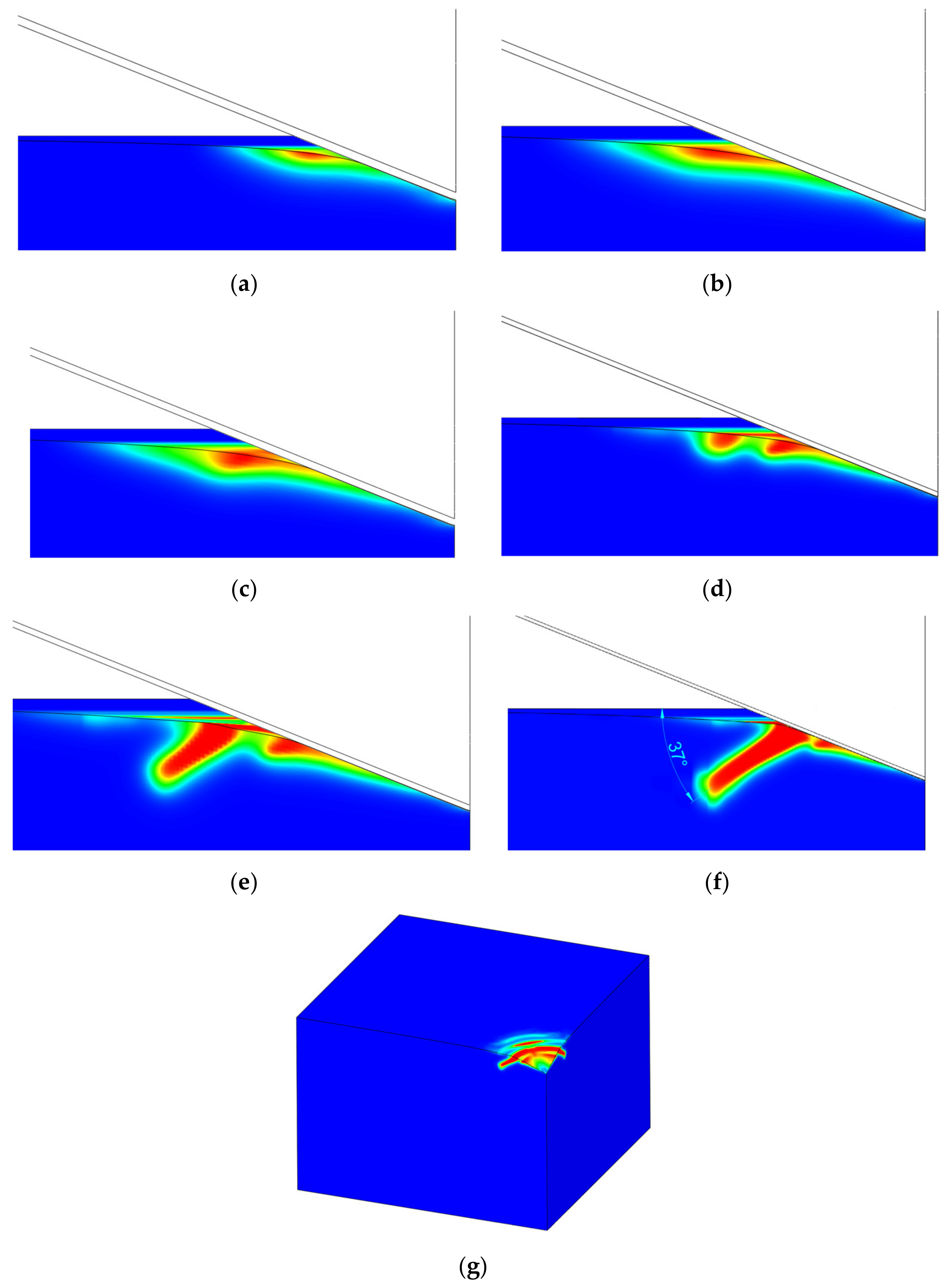
By increasing the load, the crack starts to propagate orthogonally to the surface towards the interior of the material (see the dimension,
d, in
Figure 4c). This propagation direction has been well-captured in both 2D numerical [
8,
13] and 3D experimental [
5,
6] observations. With increasing load, the crack continues to propagate with an incline angle of around 45° with respect to the surface (
Figure 4b).
As reported by recent phase-field modeling by Strobl and Seeling [
8] and Wu et al. [
14], and an experimental investigation by Kocer and Collins [
7], the Poisson’s ratio is the most influential material parameter that influences the angle of the cone crack (in case of a flat punch indenter). However, in the case of an inclined indenter (Vickers or Berkovich), the angle of the cone crack is around 40–45°, as reported by Hagan [
5] and Michel et al. [
6], which is significantly higher than the angle encountered in the flat punch indentation. In our simulation, a somewhat smaller inclination angle of the cone crack has been observed, as shown in
Figure 8f.
The primary and secondary cracks are visible in
Figure 8b. The size of the primary (small) cone crack is dependent on the friction coefficient (
Figure 6), but both are noticed in experimental measurements (
Figure 2), as well as in the relevant literature [
37].
Unlike the flat punch, where the contact area is constant, in the Vickers indentation we can expect that the indenter will pass through the crack at some point during the indentation. In terms of the numerical analysis, the crack starts to thicken. This happens when the force is just below 2000 mN. At this force, a new cone crack starts to form, again outside the contact region. Further loading leads to the formation of a new cone crack (
Figure 8g), but with a slightly smaller inclination angle.
4. Conclusions
As shown in
Section 2, from the considered energy splits, only the spectral energy split proposed by Freddi can accurately replicate cone-crack behavior. The decomposition proposed by Amor fails to model the crack since finite elements in the compression state lose their stiffness and excessive distortion of elements occurs. A similar growth of the scalar damage field was observed using the decomposition proposed by Miehe.
As can be seen from the presented results, the phase-field method is capable of modeling the cone crack formation during the Vickers indentation in fused silica if an appropriate energy split is used. The phase-field numerical model can initiate a ring on the specimen surface outside of the contact region of the indenter, as noticed by Hagan [
5] and Lawn and Evans [
9]. These indentation crack phenomena are also visible in
Figure 2, where a cone crack is formed outside the residual indent. This fact is in accordance with the Lawn and Evans theory that says that the cone crack is the dominant crack mode in the indentation of intact fused silica and that radial-median (half-penny) or lateral cracks are formed due to specimen irregularities or flaws beneath the indenter. A crack in the ideal numerical model without flaws is initiated only by a positive stress field on the surface (
Figure 7a,b). From the aspect of linear fracture mechanics (assuming brittle materials), fracture occurs, according to the principal stress hypothesis, when the maximum principal stress reaches the fracture strength of a material [
4]. This statement can also be corelated with the phase-field formulation and energy splits, where fracture occurs when one positive stress reaches the critical value.
Regarding the contact formulation, as described, the finite sliding contact is the accordance formulation, since small sliding cannot replicate the conditions appearing in the investigated cone crack. The reason for this lies in small sliding formulation, which “glues” the corresponding nodes from the master and slave surfaces. With further penetration, the nodes of the slave surface are dragged by the corresponding master nodes, which creates positive tensile stress on the specimen, i.e., the slave surface.
By further increasing the load, the crack starts to propagate orthogonally to the surface to a certain depth, firstly in the direction parallel to the loading direction and then at a certain incline angle, which corresponds well to the numerical and experimental observations conducted in the relevant literature.
Even though fused silica is usually presented as an elastic, brittle material, from the obtained experimental indentation curve (
Figure 1), it is visible that there occurs a significant plastic deformation, also visible after unloading in the form of a residual indent. The authors’ opinion is that no significant change in the crack pattern, with the introduction of a ductile phase-field formulation, will appear since the crack is still driven by only elastic deformation energy.
This research creates new questions in the numerical modeling of indentation cracking, as well as the validation of different phase-field formulations, since fused silica consists of pure silicon dioxide, SiO2, and can be assumed to be homogeneous. The use of graphic accelerated servers will enhance the computational speeds in future investigations, especially in combination with efficient adaptive remeshing and faster equation solvers. The use of a ductile formulation instead of a brittle one will possibly describe the real indentation curve even better. Additionally, the use of ductile formulation with different energy decompositions could possibly describe the radial (also median and half-penny) cracks, which appear as the second-dominant crack pattern in the fused silica indentation. This could explain why different crack patterns appear on the same specimen at the same indentation force.


 ,
, 


