Article

MoO3@MoS2 Core-Shell Structured Hybrid Anode Materials for Lithium-Ion Batteries

1
Department of Energy & Materials Engineering, Dongguk University, Seoul 04620, Korea
2
Hybrid Materials Center (HMC), Sejong University, Seoul 05006, Korea
3
Department of Nanotechnology and Advanced Materials Engineering, Sejong University, Seoul 05006, Korea
4
Advanced Analysis & Data Center, Korea Institute of Science and Technology (KIST), Seoul 02792, Korea
5
Division of Electronics and Electrical Engineering, Dongguk University-Seoul, Seoul 04620, Korea
6
Centre for Energy Storage Research, Korea Institute of Science and Technology (KIST), Seoul 02792, Korea
*
Authors to whom correspondence should be addressed.
Nanomaterials 2022, 12(12), 2008; https://doi.org/10.3390/nano12122008
Submission received: 12 May 2022 / Revised: 31 May 2022 / Accepted: 7 June 2022 / Published: 10 June 2022

Abstract

:
We explore a phase engineering strategy to improve the electrochemical performance of transition metal sulfides (TMSs) in anode materials for lithium-ion batteries (LIBs). A one-pot hydrothermal approach has been employed to synthesize MoS2 nanostructures. MoS2 and MoO3 phases can be readily controlled by straightforward calcination in the (200–300) °C temperature range. An optimized temperature of 250 °C yields a phase-engineered MoO3@MoS2 hybrid, while 200 and 300 °C produce single MoS2 and MoO3 phases. When tested in LIBs anode, the optimized MoO3@MoS2 hybrid outperforms the pristine MoS2 and MoO3 counterparts. With above 99% Coulombic efficiency (CE), the hybrid anode retains its capacity of 564 mAh g−1 after 100 cycles, and maintains a capacity of 278 mAh g−1 at 700 mA g−1 current density. These favorable characteristics are attributed to the formation of MoO3 passivation surface layer on MoS2 and reactive interfaces between the two phases, which facilitate the Li-ion insertion/extraction, successively improving MoO3@MoS2 anode performance.

Graphical Abstract

1. Introduction

For the ever-growing need for renewable resources, the energy storage area has attracted much attention to alleviate environmental catastrophe and energy difficulties caused by traditional fossil fuels [1]. In this regard, rechargeable Li-ion batteries (LIBs) have become by far the most promising energy storage systems for portable electronic devices and electric vehicles, due to their comparatively greater energy and power density, and long-cycle life [2,3,4]. Since the electrochemical properties of the active materials govern the LIB’s performance, the development of new materials for LIBs is a crucial factor. Although LIBs are receiving growing attention, a graphite anode with a theoretical capacity of 372 mAh g−1 cannot meet the challenging requirements for higher energy density [5].
To substitute for graphite, various anode materials have been explored to improve the electrochemical performance, including transition metal dichalcogenides (TMDs) [6,7,8,9,10], transition metal oxides (TMOs) [11,12,13], titanium-based materials [14,15], carbon nanomaterials [16,17], and their composite materials [18,19]. Alloying-type anodes (Si, Sn, Ge) are the other alternative candidates that can replace graphite due to their very high theoretical capacity and relatively higher working potential, beneficial for reducing the risk of dendrite formation. However, the major drawback of these alloy-type anode materials is their massive volume expansion during cycling: for instance, Si expands up to 320%, leading to the failure of the active material. Extensive studies are ongoing to fix their volume expansion and stabilize them for LIBs [20,21,22]. Anode materials of the insertion type, such as carbonaceous materials and titanium-based oxides, have limited specific capacity. Compared to these insertion-type materials, conversion-type materials have a higher theoretical capacity of (600–1000 mAh g−1) and may be ideal to meet the energy demand for large-scale energy storages [23]. Over the past several decades, TMOs, one of the conversion-type materials’ families, have been studied extensively in LIBs [23,24]. Recent research has shifted focus from transition metal oxides (TMOs) to transition metal sulfides (TMSs), due to their better electrical conductivity, mechanical and thermal stability, and higher electrochemical activity [25,26]. The majority of TMSs have 2D layered structures with a chemical composition of MSn (where n = 1 or 2, and M = Mo, W, Ti,V, or Sn). With an analogous layered structure to that of graphite anodes, 2D TMSs enable high rate capability via facile Li insertion and extraction, while the strong covalent bonding within the layers provides structural rigidity and robustness, leading to stable cyclability [27]. Even the interlayer spacings of these layer-structured TMSs are wider than graphite (~3.3 Å), for example, ~6.2 Å for MoS2, ~5.9 Å for SnS2, and ~5.7 Å for VS2 [28]. Using 2D TMSs with larger interlayer spacing can significantly reduce the diffusion barriers for Li-ions, and accommodate their expansion upon insertion. Most importantly, TMSs have a higher voltage platform compared to graphite anodes, which prevents the formation of lithium dendrites, and ensures their high safety [26]. Thanks to those advantageous properties, several TMS-based materials have shown larger Li storage capacities than graphite anodes, making them promising candidates for high-performance LIB anodes [25,26]. Molybdenum sulfide (MoS2), one of the most intriguing TMSs, has been studied in a number of applications, including nanoelectronics, electrocatalysis, and energy storage systems [29,30]. The MoS2 anode in LIBs undergoes an intercalation-assisted conversion reaction, where a Mo nanocrystal is embedded in the Li2S matrix as the final lithiated product and displays a high theoretical capacity of 670 mAh g1 [28,31].
Although TMSs materials have many advantages, there are still challenges that need to be urgently solved. A particular problem is the sulfur dissolution in electrolytes caused by soluble polysulfide intermediates that occur during Li2S formation/decomposition, which results in the loss of sulfur components, thus abruptly deteriorating the capacity [26]. Various composite strategies with transition metal oxides have been explored to address the above problems, such as the TiO2@MoS2 [32], SnO2/SnS2 [33], MoO2/MoS2 [34], MoO3/MoS2 [35], MoO3/SnS2 [36], Fe2O3/MoS2 [37], and MoS2/MnO [38], which showed improved electrochemical performance in LIBs. However, making composites with TMO materials would not be optimal for mitigating the severe shuttling of lithium polysulfide (LiPSs), since the sulfide electrode interface remains exposed to the electrolyte. Surface protection, such as introducing a metal oxide protective layer, might help reduce polysulfide shuttling by preventing the dissolution of intermediates and accumulation of the sulfur phase on the lithium counter electrode [39]. W.-H. Ryu et al. reported a WO3 protective layer on WS2 nanofiber anode material, which dramatically improves the cycling performance in a sodium-ion battery [40]. Therefore, the synergistic effect of structurally stable TMOs’ surfaces with conductive TMS cores can be the key characteristic of potentially excellent electrochemical performance.
Herein, motivated by such synergetic effects of the TMO-covered TMS hybrid structure, we have proposed an in situ formation of MoO3 on the MoS2 TMS (denoted as MoO3@MoS2) by simple post-annealing of hydrothermally synthesized MoS2. Structural characterizations have verified the formation of the MoO3@MoS2 hybrid structure. The MoO3@MoS2 hybrid anode has demonstrated much-improved cycling stability compared with the single-phase MoS2 and MoO3 counterparts, without sacrificing the high power and capacity.

2. Experimental Section

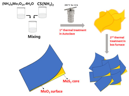
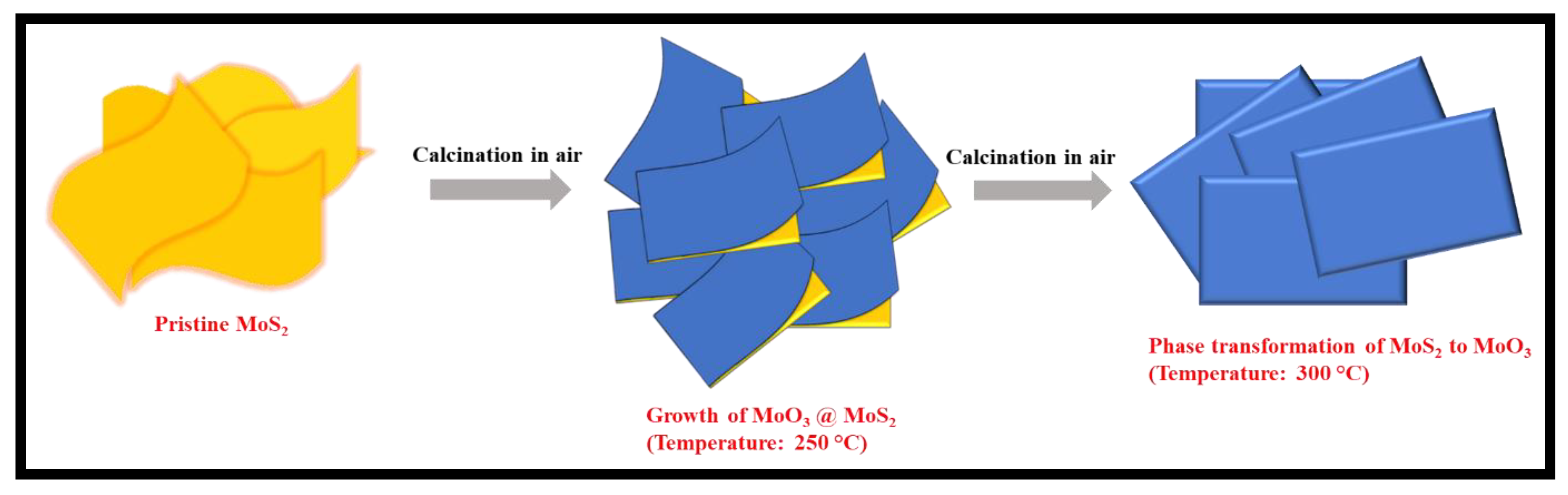
2.1. Synthesis of MoS2, MoO3@MoS2, and MoO3

The modified one-pot method was employed to synthesize the MoS2 [41]. First, thiourea (SC(NH2)2, solution A), and ammonium molybdate ((NH4)2MoO4, solution B) were dissolved in separate beakers for 30 min, followed by pouring solution B into solution A. This mixture was stirred moderately for another 30 min. Next, the transparent solution was placed into a 100 mL capacity Teflon-lined, stainless-steel autoclave, which was transferred to a convection oven programmed for the reaction at 200 °C for 12 h. After natural cooling to room temperature (RT), the black precipitates were collected, centrifuged with DI water and ethanol three times, then vacuum-dried at 100 °C for 1 h. Then, the as-synthesized MoS2 was further calcined at (200, 250, and 300) °C at a 5 °C/min rate in a box furnace. As per the structural results, the (200, 250, and 300) °C annealed samples were denoted as MoS2, MoO3@MoS2, and MoO3, respectively.

2.2. Material Characterizations

High-resolution powder X-ray diffraction (HRPD) data were collected at the 9B beamline of the Pohang Acceleration Laboratory (PAL, Pohang, South Korea), using a monochromated X-ray with a wavelength (λ) of 1.5183 Å. The Raman spectra were collected using a Renishaw inVia system with an excitation wavelength of 532 nm. X-ray photoelectron spectroscopy (XPS) measurements (Ulvac PHI X-tool spectrometer) were performed with Al–Kα X-ray radiation, to investigate the chemical and valance states of the materials. The Mo K-edge X-ray absorption spectroscopy (XAS) spectra were measured at the Pohang Accelerator Laboratory (PAL) 8C beamline, in transmission mode, and processed with Athena software. The morphology and microstructure of the powders were analyzed by field-emission scanning electron microscopy (FE-SEM, Regulus 8230, HITACHI) and transmission electron microscopy (TEM, Talos F200X, ThermoFisher). Thermogravimetric analysis (TGA) of the as-prepared sample was carried out on a NETZSCH (STA 449F3, Selb, Germany) thermal analyzer with a heating rate of 10 °C/min in open-air conditions. Electrical conductivity was evaluated using a Loresta-GP low-resistivity meter (MCP-T610, Mitsubishi Chemical corp.). The sample porosity characteristics were determined by nitrogen adsorption and desorption measurements at 77 k (Micromeritics, Norcross, GA, USA).

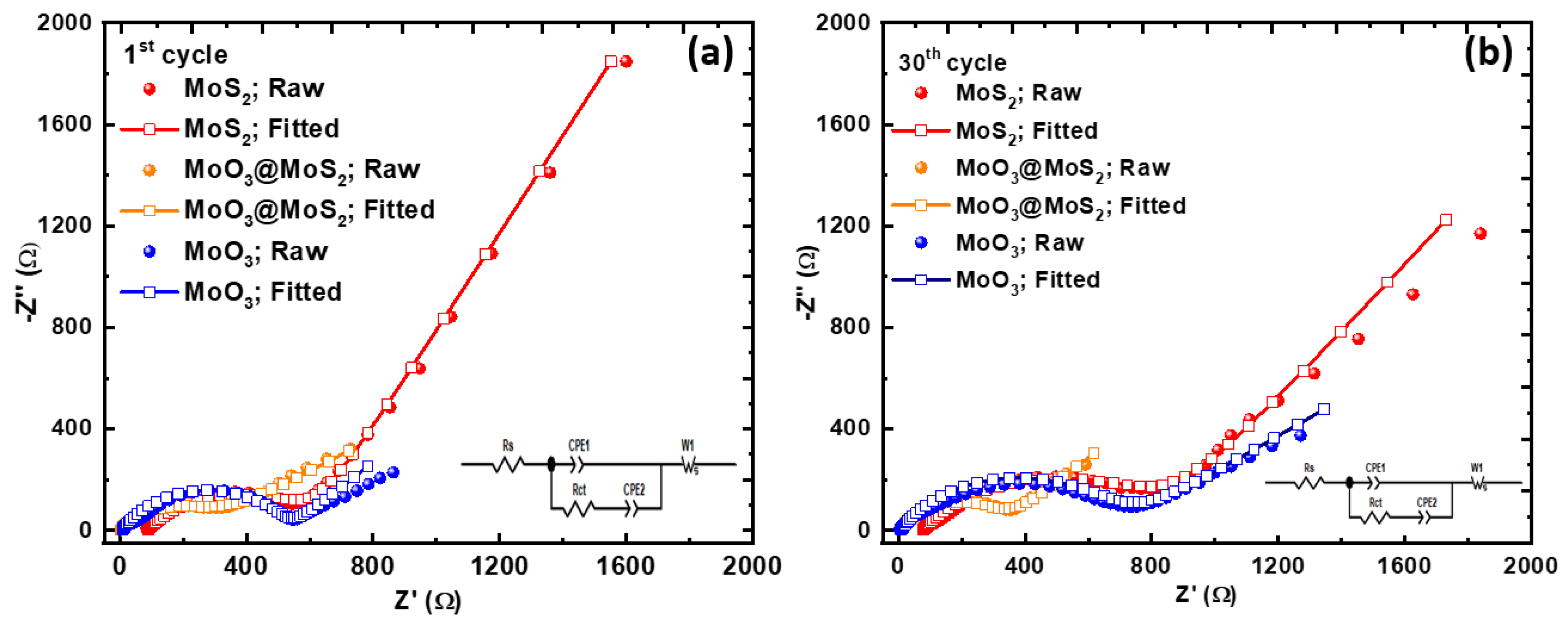
2.3. Electrochemical Measurements

The 2032-coin cells with a two-electrode configuration were used to perform the electrochemical experiments. The MoS2, MoO3@MoS2, and MoO3 powder samples were thoroughly mixed with conductive carbon black and poly(vinylidene) fluoride (PVDF) binder dissolved in N-methyl pyrrolidone (NMP) solution in an 8:1:1 weight ratio to make a viscous slurry. The working electrode was prepared using a doctor blade casting on a Cu foil current collector. The electrode loading level was controlled to be ~2.27 mg cm−2 of active material. We used a TMAX roll press machine for calendaring. The density of electrodes was calculated to be 1.8997 g/cm3. The coin cells were assembled inside a glove box filled with Ar gas, with a Li metal counter electrode, a separator (Celgard 3501), and 1.0 M LiPF6 in a 1:1 (v:v) ratio of ethylene carbonate/dimethyl carbonate with 3% FEC additive as the electrolyte. After stabilizing the coin cell for 24 h, electrochemical tests were performed using a Neware (CT-4008–5 V 10 mA-164) battery cycler at RT. A Bio-Logic electrochemical system (VMP-3) was used to measure the cyclic voltammetry (CV). The cells were cycled at different current densities (35 to 700) mA g−1 between the potential window of (0.01–3.00) V. A cyclic voltammetry (CV) test was done under a 0.1 mV s−1 scan rate within the potential window of (0.01–3.00) V. A PGSTAT 302 electrochemical workstation (Metrohm Autolab) was employed to measure the electrochemical impedance spectroscopy (EIS) in the frequency range (100 kHz to 0.01 Hz) at an open-circuit voltage (OCV).

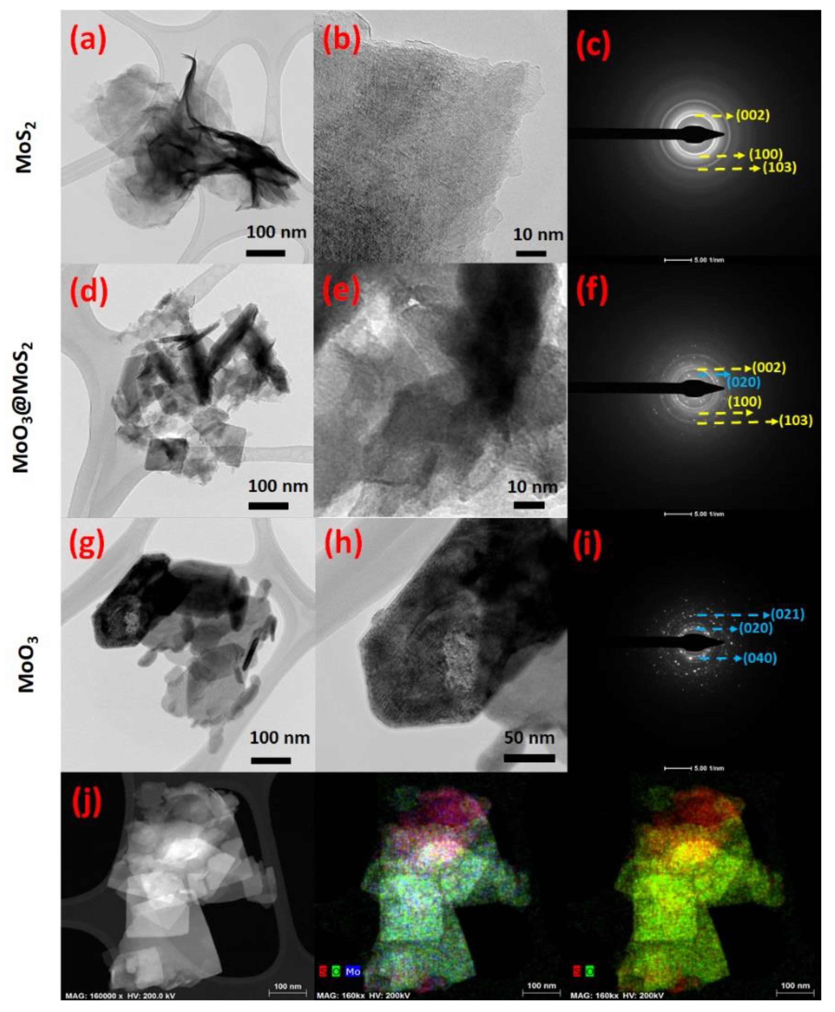
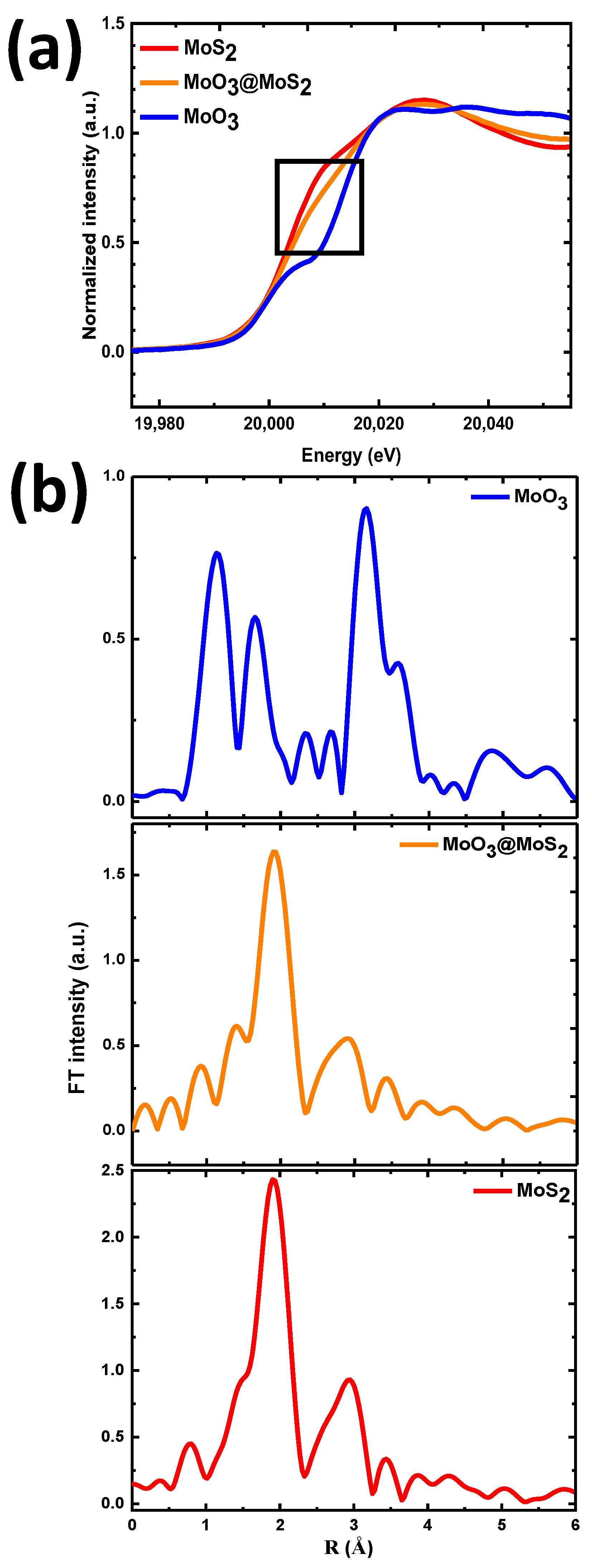
3. Results and Discussion

Scheme 1 shows a schematic of the hydrothermal reaction followed by post-annealing in the air to synthesize MoO3@MoS2 hybrid material. The SEM images in Figure 1a,b demonstrate that the as-prepared MoS2 exhibits a 2D-sheet-like morphology, reflecting its 2D hexagonal structure, similar to the previous reports [27,41]. These nanosheets are twisted together due to their curved morphology, which causes many voids between them. When annealed at 250 °C in the air, the surface of the 2D-sheet-like structures appears somewhat disrupted, associated with the potential formation of a MoO3 layer (Figure 1c,d). The presence of Mo, S, and O in the EDS (Energy dispersive spectroscopy) pattern (Figure S1 of the Supplementary Information (SI)) indicates that the MoO3@MoS2 hybrid has been successfully formed. Evidently, the MoO3@MoS2 hybrids exhibit a morphology that shows a mixture of sheet-like and particle-like characteristics, such that the surfaces appear excessively rough, in apparent contrast to the smooth surface of the pristine MoS2 nanosheets (Figure 1a). On the other hand, when the sample is further annealed at 300 °C, different sizes of cuboid-shaped grains are observed for pure MoO3 formation (Figure 1e,f).
Synchrotron-based high-resolution powder diffraction (HRPD) was used to investigate the crystal structure of the MoS2, MoO3@MoS2, and MoO3 samples, as presented in Figure 2a and Figure S2. The characteristic peaks of the MoS2 sample annealed at 200 °C match very well with those of the hexagonal-structured 2D MoS2 with the space group P63/mmc (JCPDS # 37–1492), while the intense XRD peaks for MoO3 annealed at 300 °C confirm the formation of a highly crystalline α-MoO3 phase with an orthorhombic structure and space group Pbnm (JCPDS # 35–0609). Notably, the MoO3@MoS2 sample annealed at 250 °C exhibits the diffraction peaks corresponding to both hexagonal MoS2 and orthorhombic MoO3 phases, verifying the hybrid structure formation. Notably, the MoO3 peak intensity in the MoO3@MoS2 hybrid was relatively lower than that of the MoO3 sample heated at 300 °C, suggesting the relatively lower content of the MoO3 than the MoS2. Figure S3a–c depicts the HRPD profile matching data of MoS2, MoO3@MoS2, and MoO3. The as-prepared hybrid material perfectly matches and contains the well-positioned diffraction peaks of MoS2 and MoO3. The lattice volume (v) of the MoS2 component in MoO3@MoS2 hybrid decreased by 0.71% when it was annealed at 250 °C, as shown in Table S1. The lattice volume contraction is due to the formation of the MoO3 layer, which compresses the core lattice [42]. In the hybrid, however, the MoS2 phase is not sufficiently crystallized to allow Rietveld refinement for calculating the weight fraction of MoS2 and MoO3.
Furthermore, the Raman spectra in Figure 2b also prove the successful formation of the MoO3@MoS2 hybrid, agreeing with the XRD results. The MoS2 spectrum presents the E12g (380.5 cm−1) and A1g (406 cm−1) peaks corresponding to the in-plane and out-of-plane vibration modes of Mo-S, respectively [43]. The characteristic peak for the MoO3 phase positioned at 664 cm1 belongs to B2g/B3g mode associated with the triply coordinated oxygen stretching in the 3MoO6− [44]. The Raman spectrum of the MoO3@MoS2 demonstrates the signature of both MoS2 and MoO3 peaks, confirming the formation of the MoO3@MoS2 hybrid.
XPS analysis was further performed to verify the chemical and electronic state at the sample’s surface. Figure S4 of the SI shows the survey spectrum of the MoO3@MoS2 sample, supporting the concurrent presence of Mo, S, and O elements in the prepared sample. Figure 3a compares the high-resolution Mo 3d core level XPS spectrum for the MoS2, MoO3@MoS2, and MoO3 samples. Two distinct peaks displayed at 229.3 and 232.5 eV for MoS2 correspond to Mo4+ 3d3/2 and 3d5/2 states, respectively. The high-resolution XPS spectrum of the MoO3 profile exhibits the 236.1 and 233.5 eV peaks corresponding to the Mo6+ 3d3/2 and 3d5/2 states, respectively [45]. The Mo 3d region of the MoO3@MoS2-XPS profile reveals the presence of mixed Mo6+ and Mo4+ oxidation states. Interestingly, the intensity of two distinct peaks at 236.1 and 233.5 eV associated with the MoO3 is predominant in the XPS spectra of the MoO3@MoS2 sample. Meanwhile, the two other peaks correspond to Mo4+ oxidation states associated with the MoS2 shift to low binding energy, suggesting that electron transfer occurs between MoO3 and MoS2 [37]. This finding implies that the hybrid sample shows a strong coupling between the MoS2 and MoO3 interface. Figure 3b shows the S 2p XPS region of MoS2, MoO3@MoS2, and MoO3. For MoS2, the deconvoluted S 2p profile exhibits the doublet at 162.1 and 163.2 eV, while MoO3 shows no peak, confirming that only O and Mo are present in the MoO3 sample. The MoO3@MoS2 hybrid displays a noticeable shift of the two S 2p peaks to a lower binding energy, revealing that the MoO3 surface layer influences the valence states of the S species. The spectrum also includes a weak and broad peak at 168.9 eV, likely corresponding to the S-O bond formed during the post-annealing in air [46,47]. In Figure 3c, the deconvoluted O 1s region clearly establishes the Mo-O bonding in the MoO3 and MoO3@MoS2 hybrid samples [48,49,50]. Environmental sources and complete oxidation at 300 °C are attributed to the observed weak and strong O 1s peaks of MoS2 and MoO3, respectively. When compared to the MoO3@MoS2 hybrid sample, the shallow O 1s peak supports the evolution of the MoO3 oxide layer at the MoS2 surface.
Overall, the Raman results are in complete accordance with the XRD results, but XPS results show somehow opposite behavior regarding the crystal structure of the MoO3@MoS2 hybrid sample. While XRD is a bulk probe (detected in the micrometer range), XPS is a surface probe (of a few nanometers). Based on the XPS data recorded in the Mo 3d and S 2p regions, the peak density associated with the sulfur phase dropped while the peak density for the oxide phase strengthened (Figure 3a,b), suggesting the MoS2 surface almost converted to MoO3. XRD results show that the MoS2 phase predominates over the MoO3 phase in bulk, while the XPS peaks show that the oxide phase prevails on the surface of the MoO3@MoS2 hybrid. The ratio of the integral area between oxygen and sulfur obtained from XPS survey data is 9:1 (O2p/S2p~90.42/9.58). This ratio asserts our statement that the surface of MoS2 almost converted to MoO3. In contrast, we observed 1.5 wt% loss after the oxidation process above 250 °C in the TGA curve of as-synthesized MoS2 (Figure S5). Based on the calculation (see the SI), the bulk MoO3:MoS2 ratio is approximately 1.5:8.5 in the MoO3@MoS2 hybrid. This finding confirms the results of XRD and Raman. Furthermore, another bulk probe technique, X-ray absorption spectroscopy (XAS), also exhibits a similar tendency to XRD. The Mo K-edge position of the MoO3@MoS2 hybrid is much closer to that of MoS2 spectra, as shown in Figure 4a. There are two notable peaks in the Fourier-transformed extended X-ray absorption fine structure (FT-EXAFS) spectra (without phase correction) of MoS2 at approximately 1.91 and 2.92 Å, corresponding to Mo-S and Mo-Mo interaction in the first and second coordination shells, respectively [51]. As expected, the FT-EXAFS spectrum of MoO3@MoS2 matches very well with MoS2, rather than MoO3. This finding further confirms that the MoS2 phase dominates the core of the MoO3@MoS2 hybrid, validating our XRD and Raman results. In light of these results, we conclude that the precise control of the post-annealing procedure (i.e., 250 °C in air) produces a MoO3 surface layer on the MoS2 backbone. Scheme 2 graphically presents the structural changes during the post-annealing. The optimization of the post-calcination temperature (~250 °C) is critical in tuning the surface oxidation degree of the MoO3@MoS2 hybrid, as the sulfide phase completely transforms into MoO3 at 300 °C.
The morphology and phase information of MoS2, MoO3@MoS2, and MoO3 nanostructures are further elucidated by TEM/EDS analysis, as depicted in Figure 5. The typical sheet-like morphology of MoS2 is further confirmed by TEM images (Figure 5a,b). The selected area electron diffraction (SAED) patterns in Figure 5c displays three diffraction rings for the (002), (100), and (103) lattice planes, indicating the hexagonal MoS2 polycrystalline structure (JCPDS # 37–1492). After introducing MoO3, the sheet-like structures of MoS2 are partially broken, as seen in Figure 5d,e. An enlarged TEM image shows d002 edges of the MoS2 phase (Figure S6 of the SI). The MoO3@MoS2 diffraction ring intensity appears weaker and blurrier than MoS2 on the SAED (Figure 5f), but likely relates to the MoS2 phase. This indicates that the sulfide phases are oxidized on the surface and turn into MoO3 phases, which disrupts the MoS2 crystallinity. These observations are consistent with the XRD and XPS results (Figure 2a and Figure 3). In comparison, the cuboid-shaped MoO3 (Figure 5g,h) shows entirely different SAED patterns (Figure 5i). The TEM-EDS elemental mapping (Figure 5j) indicates the uniform distribution of the Mo, S, and O species in the MoO3@MoS2 particles. It is evident that sulfur (red) exists within the particle’s core bodies, while oxide (green) is present at the surface, entirely covering the core. Figure S7a–c shows the BET sorption isotherm of MoS2, MoO3@MoS2, and MoO3 samples. The type-III isotherm profiles and absence of a hysteresis loop suggest the low porosity of all the materials. The BET surface area of MoS2, MoO3@MoS2, and MoO3 is only 8.71, 8.42, and 9.85 m2 g−1, respectively (Table S2). The pore distribution curve (Figure S7d) indicates the presence of only interparticle porosity.
The electrochemical performance of each sample was tested in the LIB half-cells. The cyclic voltammetry (CV) of the MoO3@MoS2 hybrid was measured in the voltage window of 0.01 to 3.0 V with a sweep speed of 0.1 mV s−1; the result is shown in Figure 6a. A reduction peak is located at 1.01 V, attributed to the Li-ion insertion between MoS2 layers and forming LixMoS2. Another peak positioned at 0.46 V is linked to the conversion reaction of LixMoS2 to (Mo + Li2S) [52]. These two reduction peaks shifted to a higher potential at about 1.91 and 1.15 V from the second cycle onwards. A shallow reduction peak at 0.1 V in the first cycle is the characteristic of solid electrolyte interface (SEI) formation. In the anodic scan, peaks located at 1.73 and 2.29 V are linked to the reverse conversion reaction of Mo + Li2S into MoS2, respectively [34]. The position of the oxidation peaks remains unchanged in the following cycles. Notably, a small irreversible peak at 2.11 V is found in the first cathodic scan, indicating Li+ intercalation into MoO3 crystals to generate LixMoO3 [53]. Following the first cycle, the corresponding reduction peak did not occur, suggesting that the MoS2 is the predominant participant in the redox activity of the MoS2@MoO3 hybrid anode. Therefore, it seems that the main function of MoO3 is to stabilize MoS2. Further, the observed CV shows excellent reversibility from the 2nd to 5th cycles, which indicates superior cycling stability. The observed area under the curve of the MoO3@MoS2 composite is higher than that of its pristine components (shown in Figure S8a,b in SI), indicating enhanced capacity. Figure 6b shows the galvanostatic discharge/charge (GCD) curve of MoO3@MoS2 at the current density of 50 mA g−1; where the initial cycle reveals a remarkably high reversible (charge) capacity of ~721 mAh g−1. The observed capacity is close to the theoretical limit of MoO3@MoS2 (~737 mAh g−1). Based on the TGA data (Figure S5), we estimated the theoretical capacity as described in SI. Figure S9a–c shows the extended discharge/charge curves for MoS2, MoO3@MoS2, and MoO3. When comparing the GCD curves of the three samples, it can be seen that the MoO3@MoS2 hybrid outperforms the MoS2 and MoO3 counterparts in terms of cycling stability during 100 cycles, establishing its good stability as an active anode material for LIBs. Moreover, the similar trend of the charge/discharge curve for the hybrid anode from the second cycle indicates excellent electrochemical stability and conversion reversibility. In contrast, the charge/discharge capacities for the pristine MoS2 gradually deteriorated over the 100 cycles. Figure 6c further illustrates the difference in cyclability among MoS2, MoO3@MoS2, and MoO3 anodes. The MoO3@MoS2 anode possesses a higher initial charge (reversible) capacity than MoS2 and MoO3, with a Coulombic efficiency (CE) of 80.5, 83.5, and 41.5%, respectively. There is a significant decrease in capacity for the first few cycles of the MoO3@MoS2 anode. This phenomenon is commonly observed in the conversion-based anode materials, because during the discharge-charge process of the initial cycles, the SEI layer is not fully formed. This accounts for the low CE and capacity loss during initial cycles, as reported in previous studies [6,7,8,9,10,11,12,13,14,15,16,17,18,19,20]. The CV result described earlier also accords with this behavior. However, after a few cycles, the MoO3@MoS2 anode started to stabilize and the Coulombic efficiency improved, which is a marked difference from the pristine MoS2 or MoO3 anodes. The obtained result highlights the superior Li+ storage performance of the MoO3@MoS2 anode. In addition, the MoO3@MoS2 anode demonstrates a notably higher capacity (~564 mAh g−1) than that of MoS2 (~34 mAh g−1) and MoO3 (~434 mAh g−1) at the end of 100 cycles. Compared with an anode made of pure MoS2, the MoO3@MoS2 anode exhibits enhanced electrochemical properties because of the MoO3 passivation layer on the surface of the conductive MoS2. When we disassembled cells for MoS2 and MoO3@MoS2 electrodes after 30 cycles, we observed the active material residue on the lithium foil (counter electrode) for the MoS2 anode sample. Contrary to this, there was no active material found on lithium foil (counter electrode) in the hybrid anode sample (Figure S10). During the charge/discharge cycles, MoS2 and MoO3@MoS2 anodes undergo a steady conversion process, as evidenced by their Mo K-edge EXAFS spectra measured after the 50 cycles. The FT-EXAFS spectra peaks from their 50th cycle remain almost identical to those from their pristine state (Figure S11). Figure 6d and S12 show the rate capability of the MoO3@MoS2 hybrid and its pristine components (MoS2 and MoO3). As the current densities increase from 35 to 700 mA g−1, the capacities of the MoO3@MoS2 anode decrease; but when the current density is returned to its initial value (35 mA g−1), the active material retains a high-capacity value (~434 mAh g−1). The pure MoO3 shows very poor rate performance compared to MoS2, which is attributed to the poor conductive characteristics of the oxide material, as presented in Table 1.
Figure 7a,b shows the electrochemical impedance spectroscopy (EIS) data with a fitted profile, measured after the 1st and 30th cycles, respectively. An equivalent electrical circuit is presented, where Rs is the solution resistance, Rct is the charge transfer resistance, W is Warburg impedance, while the (CPE1 and CPE2) are the constant phase elements. Figure 7a clearly shows that the semi-circle of the MoO3@MoS2 hybrid anode Nyquist plot is much smaller than its counterparts (MoS2 and MoO3) after the 1st cycle. The calculated solution resistance (Rs) and charge transfer resistance (Rct) of the hybrid anode are 2.392 and 284.308 Ω, respectively, which are lower than those of MoS2 and MoO3 (Table S3). Furthermore, after 30 cycles, the resistance of all the materials increases, but among them, MoO3@MoS2 shows much smaller resistivity. The hybrid anode material shows a lower Rct value (304.539 Ω) among the three materials (Table S4) thanks to the chemically resistive nature of oxide, which protects the sulfide phase from the dissolution into the electrolyte.

4. Conclusions

A novel, in situ approach to the synthesis of a hybrid nanostructure has been successfully optimized. This involves a two-step process of a hydrothermal reaction with subsequent air annealing. The successful formation of the MoS2 core-MoO3 shell hybrid structure was verified by XRD, Raman, XPS, and XAS results. SEM and TEM studies reveal the morphology evolution with the growth of an oxide layer on the bulk sulfide, which facilitates stable cycling stability without sacrificing the high capacity and fast-charging performance. The MoO3@MoS2 hybrid anode delivered an excellent specific charge capacity of 721 mAh g−1, a good rate-capability of 278 mAh g−1 at 700 mA g−1, and the retained capacity was ~564 mAh g−1 after 100 cycles, with excellent (~99%) Coulombic efficiency. The outstanding performance of the hybrid anode results from the synergistic interaction between the passivating layer of MoO3, which eradicates the excessive dissolution of active material, and the conducting core of MoS2, which ensures smooth electronic conduction. The work presented in this paper provides a simple, two-step, facile method to synthesize different transition metal oxide/sulfide hybrid nanostructures.

Supplementary Materials

The following supporting information can be downloaded at: https://www.mdpi.com/article/10.3390/nano12122008/s1, Figure S1: EDX spectrum of MoO3@MoS2; Figure S2: XRD of (a) MoS2 and (b) MoO3, including MoO3@MoS2, compared with their corresponding standard (PDF) data; Figure S3: Profile matching of HRPD data of (a) MoS2, (b) MoO3@MoS2, and (c) MoO3; Figure S4: XPS survey spectrum of MoS2, MoO3, and MoO3@MoS2; Figure S5: Thermogravimetric analysis (TGA) curve of as-synthesized MoS2 in air; Figure S6: HR-TEM image of the MoO3@MoS2 sample; Figure S7: (a–c) BET and (d) corresponding BJH profile of MoS2, MoO3, and MoO3@MoS2; Figure S8: CV curves of (a) MoS2 and (b) MoO3 anodes; Figure S9: GCD curves of the (a) MoS2, (b) MoO3@MoS2 and (c) MoO3; Figure S10: Photos of Li counter electrodes for the MoS2 and MoO3@MoS2 electrodes half-cells; Figure S11: Ex-situ Mo K-edge FT-EXAFS spectra of MoS2 and MoO3@MoS2 after 50 cycles; Figure S12: The galvanostatic voltage profiles (rate performance) of MoS2 and MoO3@MoS2 anodes at different current densities in LIBs; Table S1: Unit cell parameters of MoS2, MoO3@MoS2, and MoO3; Table S2: Result of BET analysis of MoS2, MoO3@MoS2, and MoO3; Table S3: Fitted solution resistance (Rs) and charge transfer resistance (Rct) values of MoS2, MoO3@MoS2, and MoO3 after 1st cycle; Table S4: Fitted solution resistance (Rs) and charge transfer resistance (Rct) values of MoS2, MoO3@MoS2, and MoO3 after 30th cycle; Table S5: Comparative table depicting electrochemical performance of selected TMO/TMS and/or carbon hybrids. References [33,36,54,55,56,57,58] were cited in Supplementary Materials.

Author Contributions

M.F.: conceptualization; investigation; visualization; writing—original draft. S.H.: investigation. M.I.: investigation; supervision; writing—review and editing. J.-Y.K., D.H., J.-H.B., D.V., B.A., S.A., H.-S.K., A.N.S. and J.J.: investigation. K.-W.N.: conceptualization; funding acquisition; resources; supervision; writing—review and editing. All authors have read and agreed to the published version of the manuscript.

Funding

This work was supported by the Ministry of Trade, Industry & Energy (MOTIE, grant No. 20012318) and by the Ministry of SMEs and Startups (MSS, grant No. S3126915).

Data Availability Statement

The data presented in this study are available on request from the corresponding author.

Conflicts of Interest

The authors declare no conflict of interest.

References

  1. Luo, W.; Shen, F.; Bommier, C.; Zhu, H.; Ji, X.; Hu, L. Na-Ion Battery Anodes: Materials and Electrochemistry. Acc. Chem. Res. 2016, 49, 231–240. [Google Scholar] [CrossRef] [PubMed]
  2. Chu, S.; Majumdar, A. Opportunities and challenges for a sustainable energy future. Nature 2012, 488, 294–303. [Google Scholar] [CrossRef] [PubMed]
  3. Ding, Y.; Cano, Z.P.; Yu, A.; Lu, J.; Chen, Z. Automotive Li-Ion Batteries: Current Status and Future Perspectives. Electrochem. Energy Rev. 2019, 2, 1–28. [Google Scholar] [CrossRef]
  4. Liang, Y.; Zhao, C.Z.; Yuan, H.; Chen, Y.; Zhang, W.; Huang, J.Q.; Yu, D.; Liu, Y.; Titirici, M.M.; Chueh, Y.L.; et al. A review of rechargeable batteries for portable electronic devices. InfoMat 2019, 1, 6–32. [Google Scholar] [CrossRef] [Green Version]
  5. Buqa, H.; Goers, D.; Holzapfel, M.; Spahr, M.E.; Novák, P. High Rate Capability of Graphite Negative Electrodes for Lithium-Ion Batteries. J. Electrochem. Soc. 2005, 152, A474. [Google Scholar] [CrossRef]
  6. Wang, X.; Zhang, Z.; Chen, Y.; Qu, Y.; Lai, Y.; Li, J. Morphology-controlled synthesis of MoS2 nanostructures with different lithium storage properties. J. Alloys Compd. 2014, 600, 84–90. [Google Scholar] [CrossRef]
  7. Zhang, S.; Chowdari, B.V.R.; Wen, Z.; Jin, J.; Yang, J. Constructing Highly Oriented Configuration by Few-Layer MoS2: Toward High-Performance Lithium-Ion Batteries and Hydrogen Evolution Reactions. ACS Nano 2015, 9, 12464–12472. [Google Scholar] [CrossRef]
  8. Radovsky, G.; Popovitz-Biro, R.; Staiger, M.; Gartsman, K.; Thomsen, C.; Lorenz, T.; Seifert, G. Tenne, Synthesis of copious amounts of SnS2 and SnS2/SnS nanotubes with ordered superstructures. Angew. Chem. 2011, 123, 12524–12528. [Google Scholar] [CrossRef]
  9. Vikraman, D.; Hussain, S.; Prasanna, K.; Karuppasamy, K.; Jung, J.; Kim, H.-S. Facile method to synthesis hybrid phase 1T@2H MoSe2 nanostructures for rechargeable lithium ion batteries. J. Electroanal. Chem. 2019, 833, 333–339. [Google Scholar] [CrossRef]
  10. Hussain, S.; Faizan, M.; Vikraman, D.; Rabani, I.; Ali, B.; Kim, H.-S.; Jung, J.; Nam, K.-W. Eutectoid WxC embedded WS2 nanosheets as a hybrid composite anode for lithium-ion batteries. Ceram. Int. 2021, 47, 18646–18655. [Google Scholar] [CrossRef]
  11. Islam, M.; Jeong, M.-G.; Ali, G.; Oh, I.-H.; Chung, K.Y.; Sun, Y.-K.; Jung, H.-G. A 4 V Li-ion battery using all-spinel-based electrodes. ChemSusChem 2018, 11, 2165–2170. [Google Scholar] [CrossRef] [PubMed]
  12. Islam, M.; Ali, G.; Akbar, M.; Ali, B.; Jeong, M.; Kim, J.; Chung, K.Y.; Nam, K.; Jung, H. Investigating the energy storage performance of the ZnMn2O4 anode for its potential application in lithium-ion batteries. Int. J. Energy Res. 2022, 46, 6444–6456. [Google Scholar] [CrossRef]
  13. Feng, Y.; Liu, H.; Liu, Y.; Li, J. Tunable oxygen deficient in MoO3−x/MoO2 heterostructure for enhanced lithium storage properties. Int. J. Energy Res. 2022, 46, 5789–5799. [Google Scholar] [CrossRef]
  14. Madian, M.; Eychmüller, A.; Giebeler, L. Current Advances in TiO2-Based Nanostructure Electrodes for High Performance Lithium Ion Batteries. Batteries 2018, 4, 7. [Google Scholar] [CrossRef] [Green Version]
  15. Chen, Z.; Belharouak, I.; Sun, Y.-K.; Amine, K. Titanium-Based Anode Materials for Safe Lithium-Ion Batteries. Adv. Funct. Mater. 2013, 13, 959–969. [Google Scholar] [CrossRef]
  16. Ding, R.; Huang, Y.; Li, G.; Liao, Q.; Wei, T.; Liu, Y.; Huang, Y.; He, H. Carbon Anode Materials for Rechargeable Alkali Metal Ion Batteries and in-situ Characterization Techniques. Front. Chem. 2020, 8, 607504. [Google Scholar] [CrossRef]
  17. Xiong, D.; Li, X.; Bai, Z.; Shan, H.; Fan, L.; Wu, C.; Li, D.; Lu, S. Superior Cathode Performance of Nitrogen-Doped Graphene Frameworks for Lithium Ion Batteries. ACS Appl. Mater. Interfaces 2017, 9, 10643–10651. [Google Scholar] [CrossRef]
  18. Chen, Y.M.; Yu, X.Y.; Li, Z.; Paik, U.; Lou, X.W. Hierarchical MoS 2 tubular structures internally wired by carbon nanotubes as a highly stable anode material for lithium-ion batteries. Sci. Adv. 2016, 2, e1600021. [Google Scholar] [CrossRef] [Green Version]
  19. Liu, X.; Wang, Y.; Yang, Y.; Lv, W.; Lian, G.; Golberg, D.; Wang, X.; Zhao, X.; Ding, Y. A MoS2/carbon hybrid anode for high-performance li-ion batteries at low temperature. Nano Energy 2020, 70, 104550. [Google Scholar] [CrossRef]
  20. Nzereogu, P.; Omah, A.; Ezema, F.; Iwuoha, E.; Nwanya, A. Anode materials for lithium-ion batteries: A review. Appl. Surf. Sci. Adv. 2022, 9, 100233. [Google Scholar] [CrossRef]
  21. Yan, Y.; Liu, Y.; Zhang, Y.; Qin, C.; Yu, H.; Bakenov, Z.; Wang, Z. Sn modified nanoporous Ge for improved lithium storage performance. J. Colloid Interface Sci. 2021, 602, 563–572. [Google Scholar] [CrossRef] [PubMed]
  22. Li, H.; Yamaguchi, T.; Matsumoto, S.; Hoshikawa, H.; Kumagai, T.; Okamoto, N.L.; Ichitsubo, T. Circumventing huge volume strain in alloy anodes of lithium batteries. Nat. Commun. 2020, 11, 1584. [Google Scholar] [CrossRef] [PubMed] [Green Version]
  23. Fang, S.; Bresser, D.; Passerini, S. Transition Metal Oxide Anodes for Electrochemical Energy Storage in Lithium- and Sodium-Ion Batteries. Adv. Energy Mater. 2020, 10, 1902485. [Google Scholar] [CrossRef]
  24. Reddy, M.V.; Rao, G.V.S.; Chowdari, B.V.R. Metal Oxides and Oxysalts as Anode Materials for Li Ion Batteries. Chem. Rev. 2013, 113, 5364–5457. [Google Scholar] [CrossRef] [PubMed]
  25. Zhao, J.; Zhang, Y.; Wang, Y.; Li, H.; Peng, Y. The application of nanostructured transition metal sulfides as anodes for lithium ion batteries. J. Energy Chem. 2018, 27, 1536–1554. [Google Scholar] [CrossRef] [Green Version]
  26. Xu, X.; Liu, W.; Kim, Y.; Cho, J. Nanostructured transition metal sulfides for lithium ion batteries: Progress and challenges. Nano Today 2014, 9, 604–630. [Google Scholar] [CrossRef]
  27. Zhang, G.; Liu, H.; Qu, J.; Li, J. Two-dimensional layered MoS2: Rational design, properties and electrochemical applications. Energy Environ. Sci. 2016, 9, 1190–1209. [Google Scholar] [CrossRef]
  28. Wu, J.; Ihsan-Ul-Haq, M.; Ciucci, F.; Huang, B.; Kim, J.-K. Rationally designed nanostructured metal chalcogenides for advanced sodium-ion batteries. Energy Storage Mater. 2021, 34, 582–628. [Google Scholar] [CrossRef]
  29. Kumar, V.P.; Panda, D.K. Review˗next generation 2D material molybdenum disulfide (MoS2): Properties, applications and challenges. ECS J. Solid State Sci. Technol. 2022, 11, 033012. [Google Scholar] [CrossRef]
  30. Zuo, J.-H.; Zhai, P.-B.; He, Q.-Q.; Wang, L.; Chen, Q.; Gu, X.-K.; Yang, Z.-L.; Gong, Y.-J. In-situ constructed three-dimensional MoS2–MoN heterostructure as the cathode of lithium–sulfur battery. Rare Met. 2022, 41, 1743–1752. [Google Scholar] [CrossRef]
  31. Zhang, L.; Sun, D.; Kang, J.; Feng, J.; Bechtel, H.A.; Wang, L.-W.; Cairns, E.J.; Guo, J. Electrochemical Reaction Mechanism of the MoS2 Electrode in a Lithium-Ion Cell Revealed by in Situ and Operando X-ray Absorption Spectroscopy. Nano Lett. 2018, 18, 1466–1475. [Google Scholar] [CrossRef] [PubMed] [Green Version]
  32. Liao, J.-Y.; de Luna, B.; Manthiram, A. TiO2-B nanowire arrays coated with layered MoS2 nanosheets for lithium and sodium storage. J. Mater. Chem. A 2016, 4, 801–806. [Google Scholar] [CrossRef]
  33. Chang, K.; Chen, W.-X.; Li, H.; Li, H. Microwave-assisted synthesis of SnS2/SnO2 composites by l-cysteine and their electrochemical performances when used as anode materials of Li-ion batteries. Electrochim. Acta 2011, 56, 2856–2861. [Google Scholar] [CrossRef]
  34. Deng, Z.; Hu, Y.; Ren, D.; Lin, S.; Jiang, H.; Li, C. Reciprocal hybridization of MoO2 nanoparticles and few-layer MoS2 for stable lithium-ion batteries. Chem. Commun. 2015, 51, 13838–13841. [Google Scholar] [CrossRef]
  35. Villevieille, C.; Wang, X.-J.; Krumeich, F.; Nesper, R.; Novák, P. MoS2 coating on MoO3 nanobelts: A novel approach for a high specific charge electrode for rechargeable Li-ion batteries. J. Power Sources 2015, 279, 636–644. [Google Scholar] [CrossRef]
  36. Hu, C.; Shu, H.; Shen, Z.; Zhao, T.; Liang, P.; Chen, X. Hierarchical MoO3/SnS2 core–shell nanowires with enhanced electrochemical performance for lithium-ion batteries. Phys. Chem. Chem. Phys. 2018, 20, 17171–17179. [Google Scholar] [CrossRef]
  37. Qu, B.; Sun, Y.; Liu, L.; Li, C.; Yu, C.; Zhang, X.; Chen, Y. Ultrasmall Fe2O3 nanoparticles/MoS2 nanosheets composite as high-performance anode material for lithium ion batteries. Sci. Rep. 2017, 7, 42772. [Google Scholar] [CrossRef]
  38. Li, Z.; Sun, P.; Zhan, X.; Zheng, Q.; Feng, T.; Braun, P.V.; Qi, S. Metallic 1T phase MoS2/MnO composites with improved cyclability for lithium-ion battery anodes. J. Alloys Compd. 2019, 796, 25–32. [Google Scholar] [CrossRef]
  39. Ahmed, B.; Anjum, D.H.; Hedhili, M.N.; Alshareef, H.N. Mechanistic insight into the stability of HfO2-coated MoS2 nanosheet anodes for sodium ion batteries. Small 2015, 11, 4341–4350. [Google Scholar] [CrossRef]
  40. Ryu, W.-H.; Wilson, H.; Sohn, S.; Li, J.; Tong, X.; Shaulsky, E.; Schroers, J.; Elimelech, M.; Taylor, A.D. Heterogeneous WSx/WO3 thorn-bush nanofiber electrodes for sodium-ion batteries. ACS Nano 2016, 10, 3257–3266. [Google Scholar] [CrossRef]
  41. Xie, J.; Zhang, J.; Li, S.; Grote, F.; Zhang, X.; Zhang, H.; Wang, R.; Lei, Y.; Pan, B.; Xie, Y. Controllable Disordered Engineering in Oxygen-Incorporated MoS2 Ultrathin Nanosheets for Efficient Hydrogen Evolution. J. Am. Chem. Soc. 2013, 135, 17881–17888. [Google Scholar] [CrossRef] [PubMed]
  42. Mishra, N.; Rathore, D.; Pandey, R.K. A comparative study of conventional type II and inverted core–shell nanostructures based on CdSe and ZnS. Opt. Quantum Electron. 2018, 50, 107. [Google Scholar] [CrossRef]
  43. Li, H.; Zhang, Q.; Yap, C.C.R.; Tay, B.K.; Edwin, T.H.T.; Olivier, A.; Baillargeat, D. From Bulk to Monolayer MoS2: Evolution of Raman Scattering. Adv. Funct. Mater. 2012, 22, 1385–1390. [Google Scholar] [CrossRef]
  44. Sinaim, H.; Ham, D.J.; Lee, J.S.; Phuruangrat, A.; Thongtem, S.; Thongtem, T. Free-polymer controlling morphology of α-MoO3 nanobelts by a facile hydrothermal synthesis, their electrochemistry for hydrogen evolution reactions and optical properties. J. Alloys Compd. 2012, 516, 172–178. [Google Scholar] [CrossRef]
  45. Vikraman, D.; Liu, H.; Hussain, S.; Karuppasamy, K.; Youi, H.-K.; Jung, J.; Kang, J.; Kim, H.-S. Influence of morphological tuned nanostructure hybrid layers on efficient bulk heterojunction organic solar cell and X-ray detector performances. Appl. Surf. Sci. 2021, 543, 148863. [Google Scholar] [CrossRef]
  46. Kim, S.S.; Britcher, L.; Kumar, S.; Griesser, H.J. XPS Study of Sulfur and Phosphorus Compounds with Different Oxidation States. Sains Malays. 2018, 47, 1913–1922. [Google Scholar] [CrossRef]
  47. Dahl-Petersen, C.; Šarić, M.; Brorson, M.; Moses, P.G.; Rossmeisl, J.; Lauritsen, J.V.; Helveg, S. Topotactic Growth of Edge-Terminated MoS2 from MoO2 Nanocrystals. ACS Nano 2018, 12, 5351–5358. [Google Scholar] [CrossRef] [Green Version]
  48. Hussain, S.; Rabani, I.; Vikraman, D.; Feroze, A.; Ali, M.; Seo, Y.-S.; Song, W.; An, K.-S.; Kim, H.-S.; Chun, S.-H.; et al. MoS2@X2C (X = Mo or W) hybrids for enhanced supercapacitor and hydrogen evolution performances. Chem. Eng. J. 2020, 421, 127843. [Google Scholar] [CrossRef]
  49. Brezesinski, T.; Wang, J.; Tolbert, S.H.; Dunn, B. Ordered mesoporous α-MoO3 with iso-oriented nanocrystalline walls for thin-film pseudocapacitors. Nat. Mater. 2010, 9, 146–151. [Google Scholar] [CrossRef]
  50. Zhou, K.; Zhou, W.; Liu, X.; Sang, Y.; Ji, S.; Li, W.; Lu, J.; Li, L.; Niu, W.; Liu, H. Ultrathin MoO3 nanocrystal self-assembled on graphene nanosheets via oxygen bonding as supercapacitor electrodes of high capacitance and long cycle life. Nano Energy 2015, 12, 510–520. [Google Scholar] [CrossRef]
  51. Zhang, H.; Lin, H.; Zheng, Y.; Hu, Y.; MacLennan, A. Understanding of the effect of synthesis temperature on the crystallization and activity of nano-MoS2 catalyst. Appl. Catal. B Environ. 2015, 165, 537–546. [Google Scholar] [CrossRef]
  52. Wang, Q.; Li, J. Facilitated lithium storage in MoS2 overlayers supported on coaxial carbon nanotubes. J. Phys. Chem. C 2007, 111, 1675–1682. [Google Scholar] [CrossRef]
  53. Cao, D.; Dai, Y.; Xie, S.; Wang, H.; Niu, C. Pyrolytic synthesis of MoO3 nanoplates within foam-like carbon nanoflakes for enhanced lithium ion storage. J. Colloid Interface Sci. 2018, 514, 686–693. [Google Scholar] [CrossRef] [PubMed]
  54. Li, X.; Li, W.; Li, M.; Cui, P.; Chen, D.; Gengenbach, T.; Chu, L.; Liu, H.; Song, G. Glucose-assisted synthesis of the hierarchical TiO2 nanowire@MoS2 nanosheet nanocomposite and its synergistic lithium storgae performance. J. Mater. Chem. A 2015, 3, 2762–2769. [Google Scholar] [CrossRef]
  55. Li, X.; Fu, J.; Sun, Y.; Sun, M.; Cheng, S.; Chen, K.; Yang, X.; Lou, Q.; Xu, T.; Shang, Y.; et al. Design and understanding of core/branch-structured VS2 nanosheets@CNTs as high-performance anode materials for lithium-ion batteries. Nanoscale 2019, 11, 13343–13353. [Google Scholar] [CrossRef]
  56. Zhu, K.; Wang, X.; Liu, J.; Li, S.; Wang, H.; Yang, L.; Liu, S.; Xie, T. Novel amorphous MoS2/MoO3/nitrogen-doped carbon composite with excellent electrochemical performance for lithium ion batteries and sodium ion batteries. ACS Sustain. Chem. Eng. 2017, 5, 8025–8034. [Google Scholar] [CrossRef]
  57. Yang, X.; Zhang, Z.; Fu, Y.; Li, Q. Porous hollow carbon spheres decorated with molybdenum diselenide nanosheets as anodes for highly reversible lithium and sodium storage. Nanoscale 2015, 7, 10198–10203. [Google Scholar] [CrossRef]
  58. Liu, M.; Gao, H.; Hu, G.; Zhu, K.; Huang, H. Facile preparation of core-shell Si@Li4Ti5O12 nanocomposite as large-capacity lithium-ion battery anode. J. Energy Chem. 2020, 40, 89–98. [Google Scholar] [CrossRef] [Green Version]
Scheme 1. Schematic of MoO3@MoS2 synthesis.
Nanomaterials 12 02008 sch001
Figure 1. FE-SEM images for (a,b) MoS2, (c,d) MoO3@MoS2, and (e,f) MoO3.
Nanomaterials 12 02008 g001
Figure 2. (a) HRPD and (b) Raman spectra of MoS2, MoO3@MoS2, and MoO3.
Nanomaterials 12 02008 g002
Figure 3. (a) Mo 3d, (b) S 2p, and (c) O 1s XPS spectra of MoS2, MoO3@MoS2, and MoO3.
Nanomaterials 12 02008 g003
Figure 4. Mo K-edge (a) XANES, and (b) FT-EXAFS spectra, of MoS2, MoO3@MoS2, and MoO3.
Nanomaterials 12 02008 g004
Scheme 2. Schematic of the phase transformation of MoS2 between (~200 and ~300) °C.
Nanomaterials 12 02008 sch002
Figure 5. TEM images and corresponding SAED pattern of (ac) MoS2, (df) MoO3@MoS2, (gi) MoO3. (j) TEM-EDS mapping image of MoO3@MoS2.
Nanomaterials 12 02008 g005
Figure 6. (a) CV and (b) discharge/charge profiles of MoO3@MoS2 between (0.01 and 3.00) V. (c) Comparative cycling performance at a current density of 50 mA g−1 and (d) rate performance of MoS2, MoO3@MoS2, and MoO3 anodes in LIBs.
Nanomaterials 12 02008 g006
Figure 7. EIS profiles of MoS2, MoO3@MoS2, and MoO3 (a) after the 1st cycle, and (b) after the 30th cycle.
Nanomaterials 12 02008 g007
Table 1. Electrical conductivity measurement (by four-point probe) results.
Serial No.MaterialAverage Electrical Conductivity (µS·cm2)
01MoS25.2442
02MoO3@MoS20.6443
03MoO30.0282
Publisher’s Note: MDPI stays neutral with regard to jurisdictional claims in published maps and institutional affiliations.

