
Sequential Synthesis Methodology Yielding Well-Defined Porous 75%SrTiO3/25%NiFe2O4 Nanocomposite


 ,
,  , , , ,
  and
and
Abstract
:1. Introduction
2. Materials and Methods
2.1. Porous Heterostructure Foams 100−xSTO/xNFO Multistep Synthesis Method
2.2. Porous Heterostructure 100−xSTO/xNFO Characterization
3. Results
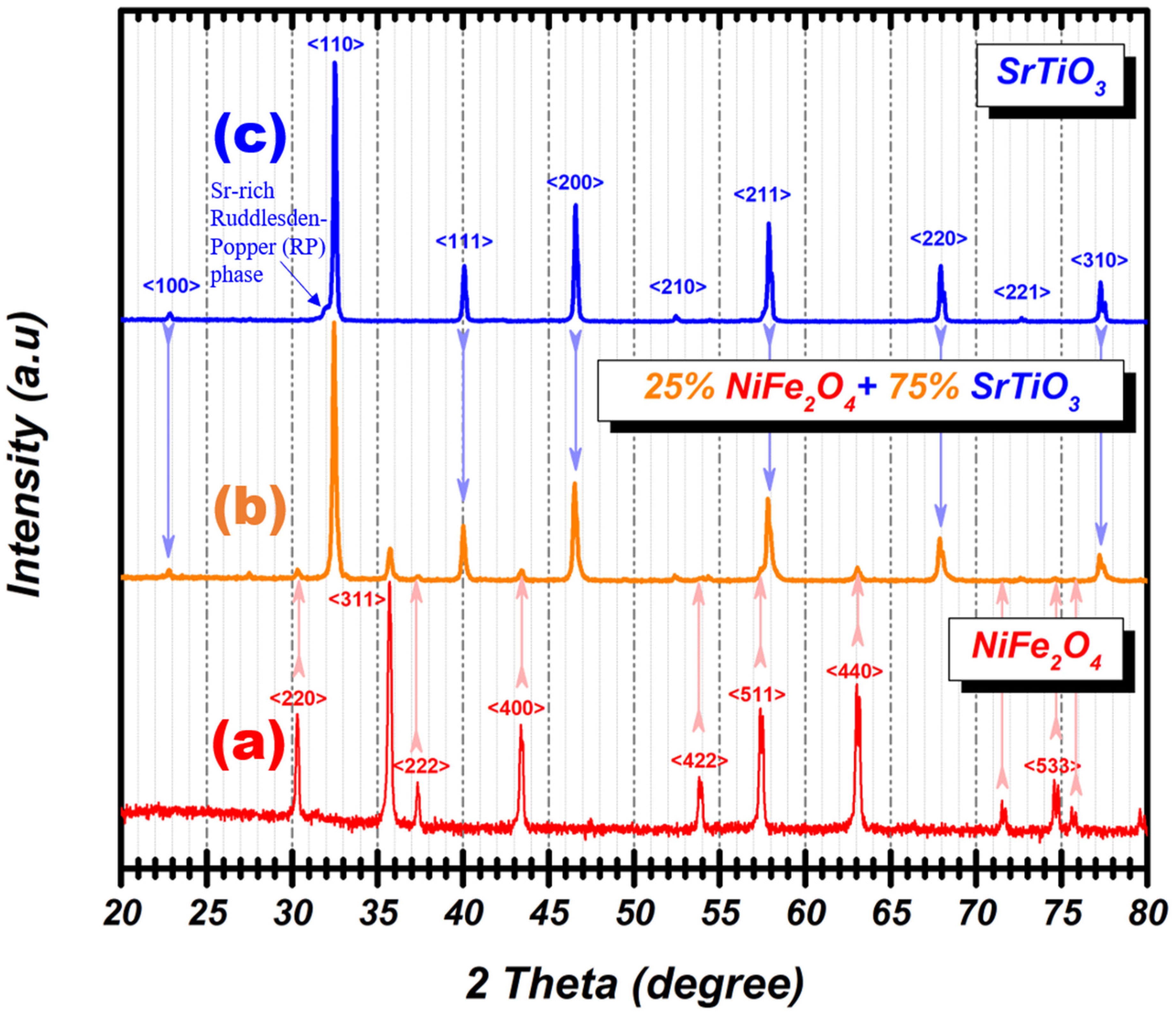
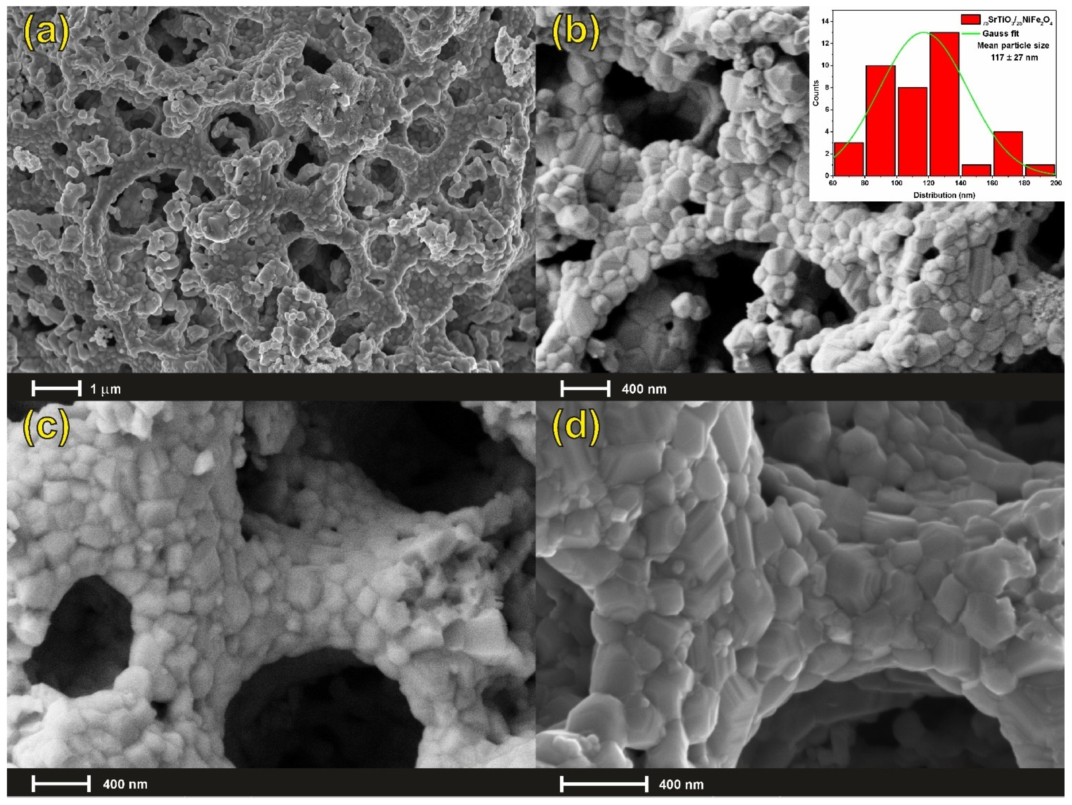
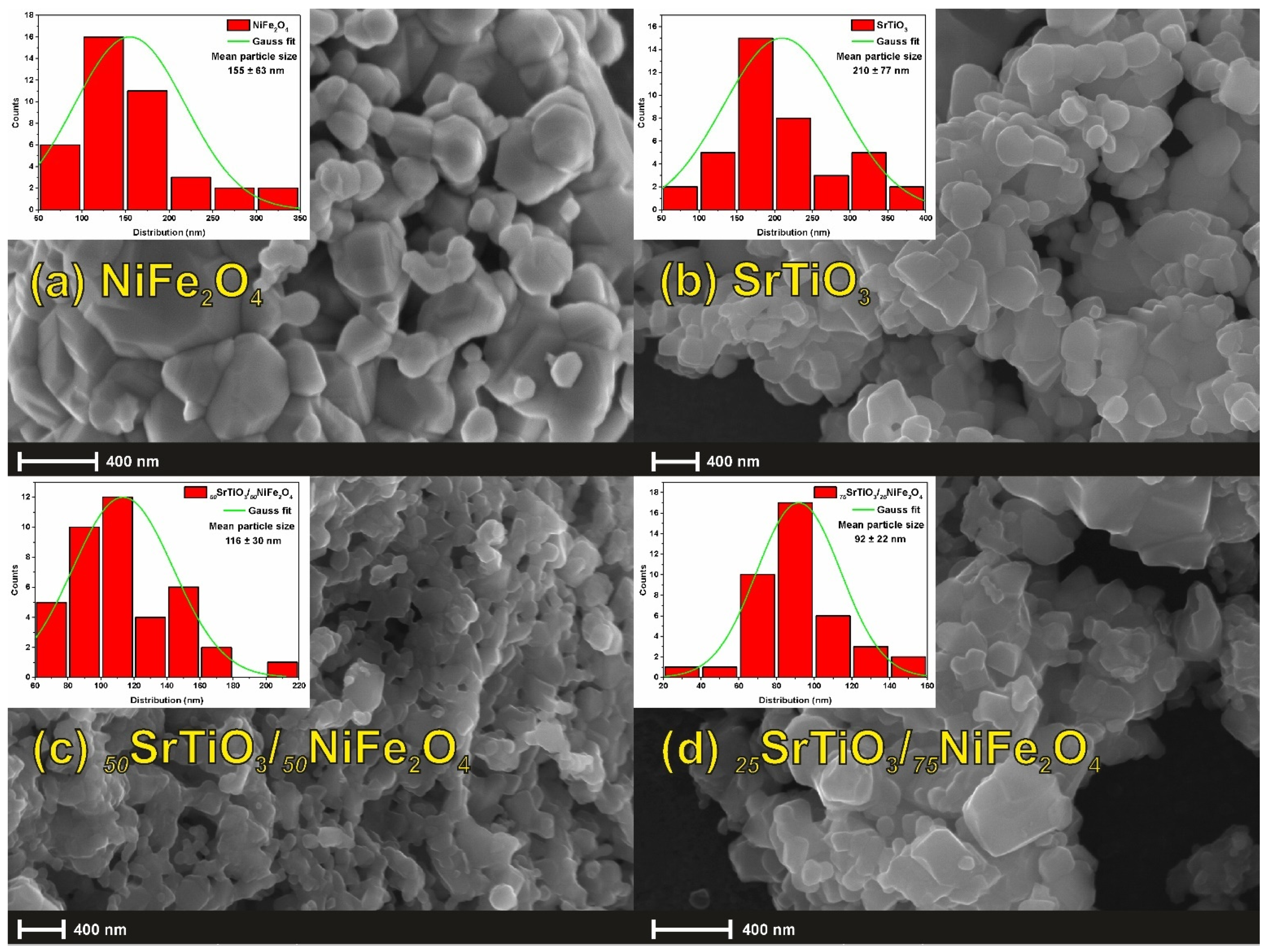
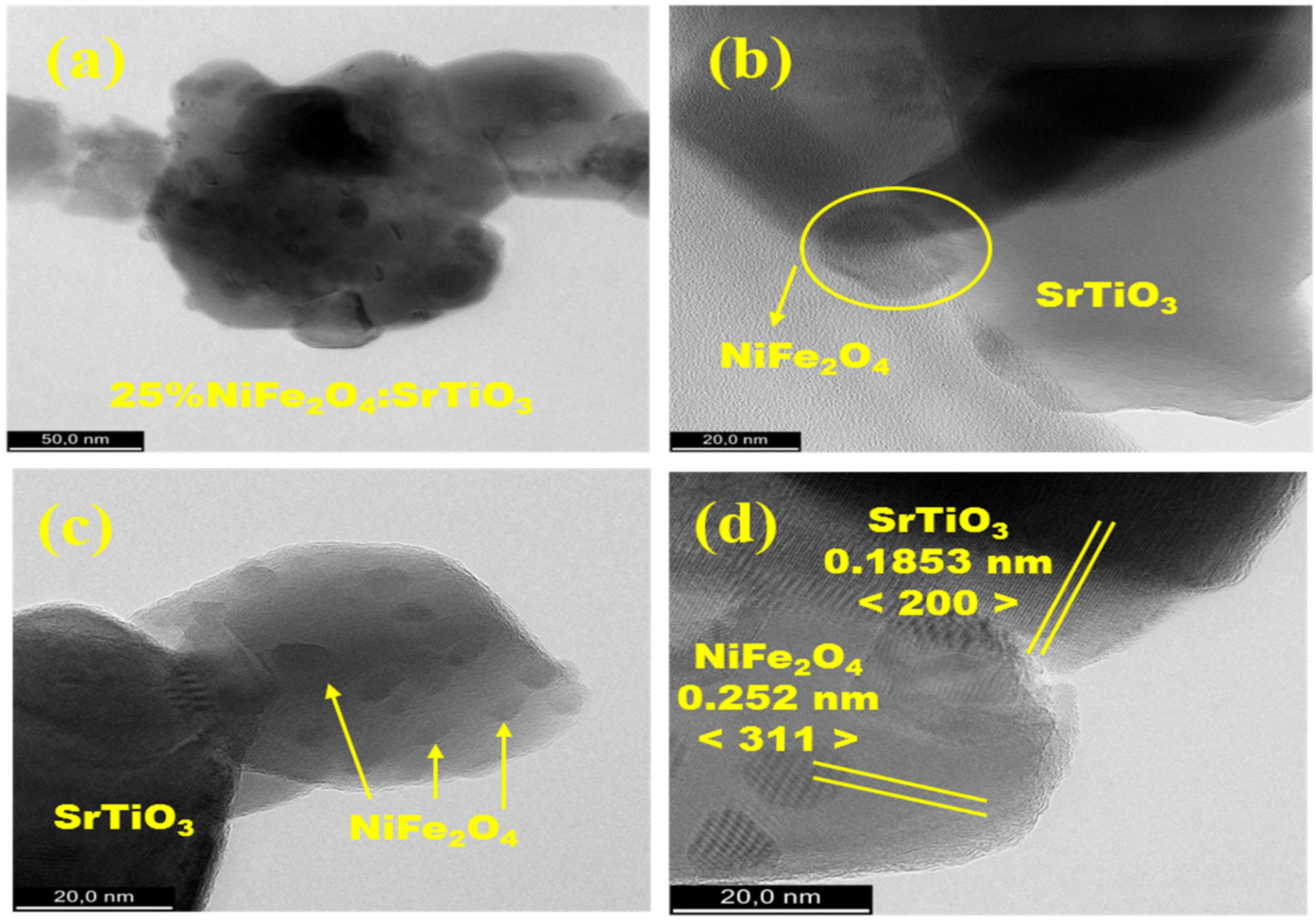
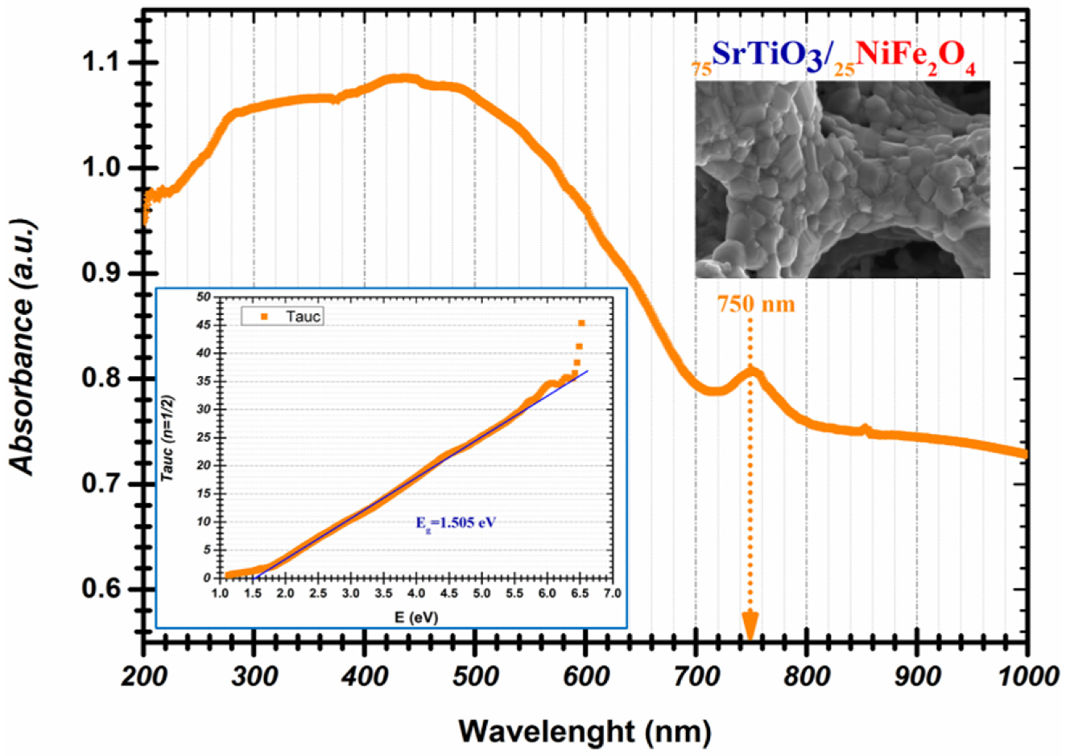
3.1. Microstructural Characterization
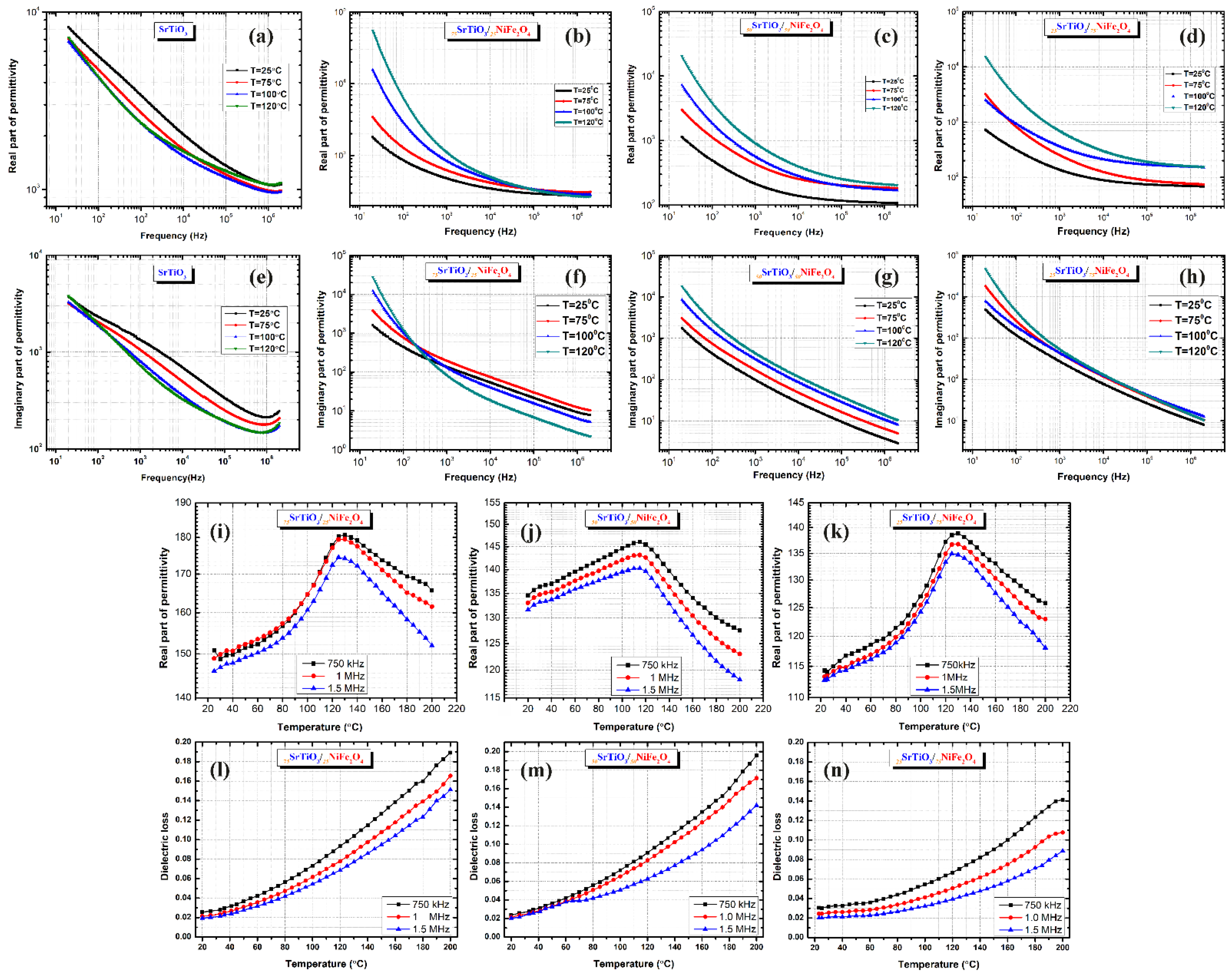
3.2. Comparative Analysis of the Dielectric Properties
4. Conclusions
Supplementary Materials
Author Contributions
Funding
Data Availability Statement
Conflicts of Interest
References
- Zheng, H.; Zhan, Q.; Zavaliche, F.; Sherburne, M.; Straub, F.; Cruz, M.P.; Chen, L.-Q.; Dahmen, U.; Ramesh, R. Controlling self-assembled perovskite− spinel nanostructures. Nano Lett. 2006, 6, 1401–1407. [Google Scholar] [CrossRef] [PubMed]
- Lendlein, A.; Trask, R.S. Multifunctional materials: Concepts, function-structure relationships, knowledge-based design, translational materials research. Multifunct. Mater. 2018, 1, 10201. [Google Scholar] [CrossRef]
- Gibson, R.F. A review of recent research on mechanics of multifunctional composite materials and structures. Compos. Struct. 2010, 92, 2793–2810. [Google Scholar] [CrossRef]
- Ren, K.; Zheng, R.; Xu, P.; Cheng, D.; Huo, W.; Yu, J.; Zhang, Z.; Sun, Q. Electronic and Optical Properties of Atomic-Scale Heterostructure Based on MXene and MN (M= Al, Ga): A DFT Investigation. Nanomaterials 2021, 11, 2236. [Google Scholar] [CrossRef] [PubMed]
- Ren, K.; Sun, M.; Luo, Y.; Wang, S.; Yu, J.; Tang, W. First-principle study of electronic and optical properties of two-dimensional materials-based heterostructures based on transition metal dichalcogenides and boron phosphide. Appl. Surf. Sci. 2019, 476, 70–75. [Google Scholar] [CrossRef]
- Chen, Y.; Lai, Z.; Zhang, X.; Fan, Z.; He, Q.; Tan, C.; Zhang, H. Phase engineering of nanomaterials. Nat. Rev. Chem. 2020, 4, 243–256. [Google Scholar] [CrossRef]
- Reunchan, P.; Ouyang, S.; Umezawa, N.; Xu, H.; Zhang, Y.; Ye, J. Theoretical design of highly active SrTiO 3-based photocatalysts by a codoping scheme towards solar energy utilization for hydrogen production. J. Mater. Chem. A 2013, 1, 4221–4227. [Google Scholar] [CrossRef] [Green Version]
- Jing, P.; Du, J.; Wang, J.; Lan, W.; Pan, L.; Li, J.; Wei, J.; Cao, D.; Zhang, X.; Zhao, C.; et al. Hierarchical SrTiO3/NiFe2O4 composite nanostructures with excellent light response and magnetic performance synthesized toward enhanced photocatalytic activity. Nanoscale 2015, 7, 14738–14746. [Google Scholar] [CrossRef]
- Vivek, S.; Geetha, P.; Saravanan, V.; Kumar, A.S.; Lekha, C.S.C.; Sudheendran, K.; Anantharaman, M.R.; Nair, S.S. Magnetoelectric coupling in strained strontium titanate and Metglas based magnetoelectric trilayer. J. Alloys Compd. 2019, 789, 1056–1061. [Google Scholar] [CrossRef]
- Coey, J.M.D.; Venkatesan, M.; Stamenov, P. Surface magnetism of strontium titanate. J. Phys. Condens. Matter 2016, 28, 485001. [Google Scholar] [CrossRef] [PubMed] [Green Version]
- Kleemann, W.; Dec, J.; Tkach, A.; Vilarinho, P.M. SrTiO3—Glimpses of an Inexhaustible Source of Novel Solid State Phenomena. Condens. Matter 2020, 5, 58. [Google Scholar] [CrossRef]
- Bannikov, V.V.; Shein, I.R.; Kozhevnikov, V.L.; Ivanovskii, A.L. Magnetism without magnetic ions in non-magnetic perovskites SrTiO3, SrZrO3 and SrSnO3. J. Magn. Magn. Mater. 2008, 320, 936–942. [Google Scholar] [CrossRef]
- Ke, H.; Zhang, H.; Zhou, J.; Jia, D.; Zhou, Y. Room-temperature multiferroic and magnetodielectric properties of SrTiO3/NiFe2O4 composite ceramics. Ceram. Int. 2019, 45, 8238–8242. [Google Scholar] [CrossRef]
- Jian, G.; Xue, F.; Zhang, C.; Yan, C.; Zhao, N.; Wong, C.P. Orientation dependence of elastic and piezomagnetic properties in NiFe2O4. J. Magn. Magn. Mater. 2017, 442, 141–144. [Google Scholar] [CrossRef]
- Dey, P.; Debnath, R.; Singh, S.; Mandal, S.K.; Roy, J.N. Irreversibility in room temperature current–voltage characteristics of NiFe2O4 nanoparticles: A signature of electrical memory effect. J. Magn. Magn. Mater. 2017, 421, 132–137. [Google Scholar] [CrossRef]
- Jin, R.; Jiang, H.; Sun, Y.; Ma, Y.; Li, H.; Chen, G. Fabrication of NiFe2O4/C hollow spheres constructed by mesoporous nanospheres for high-performance lithium-ion batteries. Chem. Eng. J. 2016, 303, 501–510. [Google Scholar] [CrossRef]
- Xu, R.; Huang, J.; Barnard, E.S.; Hong, S.S.; Singh, P.; Wong, E.K.; Jansen, T.; Harbola, V.; Xiao, J.; Wang, B.Y. Strain-induced room-temperature ferroelectricity in SrTiO3 membranes. Nat. Commun. 2020, 11, 1–8. [Google Scholar]
- He, J.; Lu, X.; Zhu, W.; Hou, Y.; Ti, R.; Huang, F.; Lu, X.; Xu, T.; Su, J.; Zhu, J. Induction and control of room-temperature ferromagnetism in dilute Fe-doped SrTiO3 ceramics. Appl. Phys. Lett. 2015, 107, 12409. [Google Scholar] [CrossRef]
- Zhang, W.; Li, H.-P.; Pan, W. Ferromagnetism in electrospun Co-doped SrTiO3 nanofibers. J. Mater. Sci. 2012, 47, 8216–8222. [Google Scholar] [CrossRef]
- Zhu, H.-Y.; Jiang, R.; Fu, Y.-Q.; Li, R.-R.; Yao, J.; Jiang, S.-T. Novel multifunctional NiFe2O4/ZnO hybrids for dye removal by adsorption, photocatalysis and magnetic separation. Appl. Surf. Sci. 2016, 369, 1–10. [Google Scholar] [CrossRef]
- Gorgizadeh, M.; Azarpira, N.; Sattarahmady, N. In vitro and in vivo tumor annihilation by near-infrared photothermal effect of a NiFe2O4/C nanocomposite. Colloids Surf. B Biointerfaces 2018, 170, 393–400. [Google Scholar] [CrossRef]
- Rodrigues, A.R.O.; Rio, I.S.R.; Coutinho, E.M.S.; Coutinho, P.J.G. Development of NiFe2O4/Au nanoparticles covered with lipid bilayers for applications in combined cancer therapy. In Proceedings of the Fourth International Conference on Applications of Optics and Photonics, Lisbon, Portuga, 31 May–4 June 2019; Volume 11207, p. 112071O. [Google Scholar]
- Cabral, T.C.S.; Ardisson, J.D.; de Miranda, M.C.; Gomes, D.A.; Fernandez-Outon, L.E.; Sousa, E.M.B.; Ferreira, T.H. Boron nitride nanotube@NiFe2O4: A highly efficient system for magnetohyperthermia therapy. Nanomedicine 2019, 14, 3075–3088. [Google Scholar] [CrossRef]
- Zhang, Y.; Xie, M.; Roscow, J.; Bao, Y.; Zhou, K.; Zhang, D.; Bowen, C.R. Enhanced pyroelectric and piezoelectric properties of PZT with aligned porosity for energy harvesting applications. J. Mater. Chem. A 2017, 5, 6569–6580. [Google Scholar] [CrossRef] [PubMed] [Green Version]
- Roscow, J.I.; Lewis, R.W.C.; Taylor, J.; Bowen, C.R. Modelling and fabrication of porous sandwich layer barium titanate with improved piezoelectric energy harvesting figures of merit. Acta Mater. 2017, 128, 207–217. [Google Scholar] [CrossRef]
- Castro, A.; Morère, J.; Cabañas, A.; Ferreira, L.P.; Godinho, M.; Ferreira, P.; Vilarinho, P.M. Designing nanocomposites using supercritical CO2 to insert Ni nanoparticles into the pores of nanopatterned BaTiO3 thin films. J. Mater. Chem. C 2017, 5, 1083–1089. [Google Scholar] [CrossRef]
- Castro, A.; Martins, M.A.; Ferreira, L.P.; Godinho, M.; Vilarinho, P.M.; Ferreira, P. Multifunctional nanopatterned porous bismuth ferrite thin films. J. Mater. Chem. C 2019, 7, 7788–7797. [Google Scholar] [CrossRef] [Green Version]
- Baumgartner, J.; Dey, A.; Bomans, P.H.H.; Le Coadou, C.; Fratzl, P.; Sommerdijk, N.A.J.M.; Faivre, D. Nucleation and growth of magnetite from solution. Nat. Mater. 2013, 12, 310–314. [Google Scholar] [CrossRef]
- Deshpande, K.; Mukasyan, A.; Varma, A. Direct synthesis of iron oxide nanopowders by the combustion approach: Reaction mechanism and properties. Chem. Mater. 2004, 16, 4896–4904. [Google Scholar] [CrossRef]
- George, C.N.; Thomas, J.K.; Jose, R.; Kumar, H.P.; Suresh, M.K.; Kumar, V.R.; Wariar, P.R.S.; Koshy, J. Synthesis and characterization of nanocrystalline strontium titanate through a modified combustion method and its sintering and dielectric properties. J. Alloys Compd. 2009, 486, 711–715. [Google Scholar] [CrossRef]
- Leventis, N.; Chandrasekaran, N.; Sadekar, A.G.; Sotiriou-Leventis, C.; Lu, H. One-pot synthesis of interpenetrating inorganic/organic networks of CuO/resorcinol-formaldehyde aerogels: Nanostructured energetic materials. J. Am. Chem. Soc. 2009, 131, 4576–4577. [Google Scholar] [CrossRef]
- Brun, N.; García-González, C.A.; Smirnova, I.; Titirici, M.M. Hydrothermal synthesis of highly porous carbon monoliths from carbohydrates and phloroglucinol. RSC Adv. 2013, 3, 17088–17096. [Google Scholar] [CrossRef]
- Zhang, X.; Han, D.; Hua, Z.; Yang, S. Porous Fe3O4 and gamma-Fe2O3 foams synthesized in air by sol-gel autocombustion. J. Alloys Compd. 2016, 684, 120–124. [Google Scholar] [CrossRef]
- Xia, Y.; He, Z.; Lu, Y.; Tang, B.; Sun, S.; Su, J.; Li, X. Fabrication and photocatalytic property of magnetic SrTiO3/NiFe2O4 heterojunction nanocomposites. RSC Adv. 2018, 8, 5441–5450. [Google Scholar] [CrossRef] [Green Version]
- Kočí, K.; Obalová, L.; Matějová, L.; Plachá, D.; Lacný, Z.; Jirkovský, J.; Šolcová, O. Effect of TiO2 particle size on the photocatalytic reduction of CO2. Appl. Catal. B Environ. 2009, 89, 494–502. [Google Scholar] [CrossRef]
- Viennois, R.; Hermet, P.; Machon, D.; Koza, M.M.; Bourgogne, D.; Fraisse, B.; Petrović, A.P.; Maurin, D. Stability and Lattice Dynamics of Ruddlesden–Popper Tetragonal Sr2TiO4. J. Phys. Chem. C 2020, 124, 27882–27893. [Google Scholar] [CrossRef]
- Ge, W.; Zhu, C.; An, H.; Li, Z.; Tang, G.; Hou, D. Sol–gel synthesis and dielectric properties of Ruddlesden–Popper phase Srn+1TinO3n+1 (n = 1, 2, 3, ∞). Ceram. Int. 2014, 40, 1569–1574. [Google Scholar] [CrossRef]
- Luque, R.; Campelo, J.M.; Luna, D.; Marinas, J.M.; Romero, A.A. Catalytic performance of Al-MCM-41 materials in the N-alkylation of aniline. J. Mol. Catal. A Chem. 2007, 269, 190–196. [Google Scholar] [CrossRef]
- Kruk, M.; Jaroniec, M. Gas adsorption characterization of ordered organic− inorganic nanocomposite materials. Chem. Mater. 2001, 13, 3169–3183. [Google Scholar] [CrossRef]
- Walerczyk, W.; Zawadzki, M.; Grabowska, H. Solvothermal Synthesis and Catalytic Properties of Nanocrystalline ZnFe2−xAlxO4 (x = 0, 1, 2) Spinels in Aniline Methylation. Catal. Letters 2012, 142, 71–80. [Google Scholar] [CrossRef]
- Li, Y.; Zhou, X.; Luo, W.; Cheng, X.; Zhu, Y.; El-Toni, A.M.; Khan, A.; Deng, Y.; Zhao, D. Pore Engineering of Mesoporous Tungsten Oxides for Ultrasensitive Gas Sensing. Adv. Mater. Interfaces 2019, 6(1), 1801269. [Google Scholar] [CrossRef]
- Han, S.; Hyeon, T. Simple silica-particle template synthesis of mesoporous carbons. Chem. Commun. 1999, 19, 1955–1956. [Google Scholar] [CrossRef]
- Kushwaha, S.; Sreelatha, G.; Padmaja, P. Physical and chemical modified forms of palm shell: Preparation, characterization and preliminary assessment as adsorbents. J. Porous Mater. 2013, 20, 21–36. [Google Scholar] [CrossRef]
- Zeng, K.; Zhang, D. Recent progress in alkaline water electrolysis for hydrogen production and applications. Prog. Energy Combust. Sci. 2010, 36, 307–326. [Google Scholar] [CrossRef]
- Borhan, A.I.; Gherca, D.; Cojocaru, Ş.; Lupu, N.; Roman, T.; Zaharia, M.; Palamaru, M.N.; Iordan, A.R. One-pot synthesis of hierarchical magnetic porous γ-Fe2O3@NiFe2O4 composite with solid-phase morphology changes promoted by adsorption of anionic azo-dye. Mater. Res. Bull. 2020, 122, 110664. [Google Scholar] [CrossRef]
- Yu, Z.; Ang, C. Maxwell–Wagner polarization in ceramic composites BaTiO3–(Ni0.3Zn0.7)Fe2.1O4. J. Appl. Phys. 2002, 91, 794–797. [Google Scholar] [CrossRef]
- Zeng, F.; Cao, M.; Zhang, L.; Liu, M.; Hao, H.; Yao, Z.; Liu, H. Microstructure and dielectric properties of SrTiO3 ceramics by controlled growth of silica shells on SrTiO3 nanoparticles. Ceram. Int. 2017, 43, 7710–7716. [Google Scholar] [CrossRef]
- Jonscher, A.K. Dielectric Relaxation in Solids; Chelsea Dielectrics Press Limited: London, UK, 1983. [Google Scholar]
- Li, G.; Liu, H.; Wang, Z.; Hao, H.; Yao, Z.; Cao, M.; Yu, Z. Dielectric properties and relaxation behavior of Sm substituted SrTiO3 ceramics. J. Mater. Sci. Mater. Electron. 2014, 25, 4418–4424. [Google Scholar] [CrossRef]
- Lu, S.G.; Xu, Z.K.; Wang, Y.P.; Guo, S.S.; Chen, H.; Li, T.L.; Or, S.W. Effect of CoFe2O4 content on the dielectric and magnetoelectric properties in Pb(ZrTi)O3/CoFe2O4 composite. J. Electroceramics 2008, 21, 398. [Google Scholar] [CrossRef]
- Bammannavar, B.K.; Naik, L.R. Electrical properties and magnetoelectric effect in (x) Ni0.5Zn0.5 Fe2O 4+(1−x) BPZT composites. Smart Mater. Struct. 2009, 18, 085013. [Google Scholar] [CrossRef]
- Pei, Y.; Li, Q.; Shi, W.; Zhang, B.; Chen, Q.; Yue, X.; Xiao, D.; Zhu, J. Effect of CoFe2O4 content on the dielectric and magnetoelectric properties in CoFe2O4/Pb (Mg1/3Nb2/3)0.35 Ti0.65O3 composites. Ferroelectrics 2010, 410, 82–87. [Google Scholar] [CrossRef]


| Sample | Space Group | Direct Cell Parameters (Å) | Direct Cell Volume (Å3) | Reliability Factors |
|---|---|---|---|---|
| SrTiO3 | P m -3 m | a = b = c = 3.9034(3) | 59.476(3) | 0.796/0.899 |
| NiFe2O4 | F d -3 m | a = b = c = 8.3402(3) | 580.141(4) | 1.79/3.97 |
| TiO2 | P 42/m n m | a = b = 4.5912(2) c = 2.9697(6) | 62.601(4) | 5.01/13.2 |
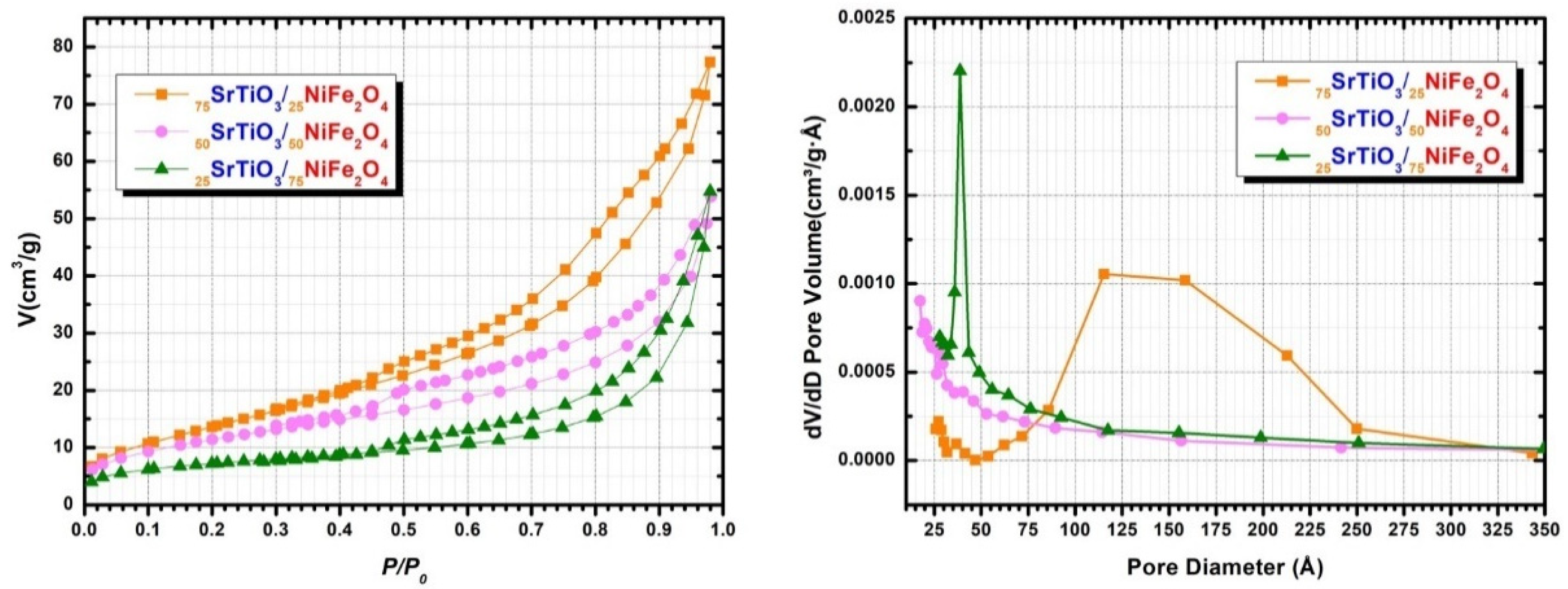
| Sample | BET Surface Area (m2 g−1) | Langmuir Surface Area (m2 g−1) | Volume of Pores (Adsorption) (cm3 g−1) | Volume of Pores (Desorption) (cm3 g−1) | Average Pore Width (Adsorption) (nm) | Average Pore Width (Desorption) (nm) |
|---|---|---|---|---|---|---|
| 75STO/25NFO | 52 ± 1 | 75 ± 1 | 0.148 ± 0.004 | 0.146 ± 0.004 | 15.86 ± 0.91 | 13.97 ± 0.78 |
| 50STO/50NFO | 39 ± 1 | 59 ± 3 | 0.082 ± 0.001 | 0.074± 0.003 | 8.30 ± 0.77 | 7.44 ± 0.97 |
| 25STO/75NFO | 25 ± 2 | 36 ± 1 | 0.078 ± 0.002 | 0.074 ± 0.006 | 7.76 ± 1.12 | 7.36 ± 0.64 |
| Compound | Composition | Band Gap Values (eV) | References |
|---|---|---|---|
| SrTiO3 | pristine | 3.20 | [7] |
| SrTiO3 | pristine | 3.15 | [34] |
| NiFe2O4 | pristine | 1.70 | [44] |
| NiFe2O4 | pristine | 1.82 | [34] |
| NiFe2O4 | pristine | 1.40 | [45] |
| γ-Fe2O3@NiFe2O4 | 50% γ-Fe2O3 50% NiFe2O4 | 1.38 | [45] |
| SrTiO3/NiFe2O4 | 15% SrTiO3 85% NiFe2O4 | 1.42 | [34] |
| 75STO/25NFO | 75% SrTiO3 25% NiFe2O4 | 1.50 | This Study |
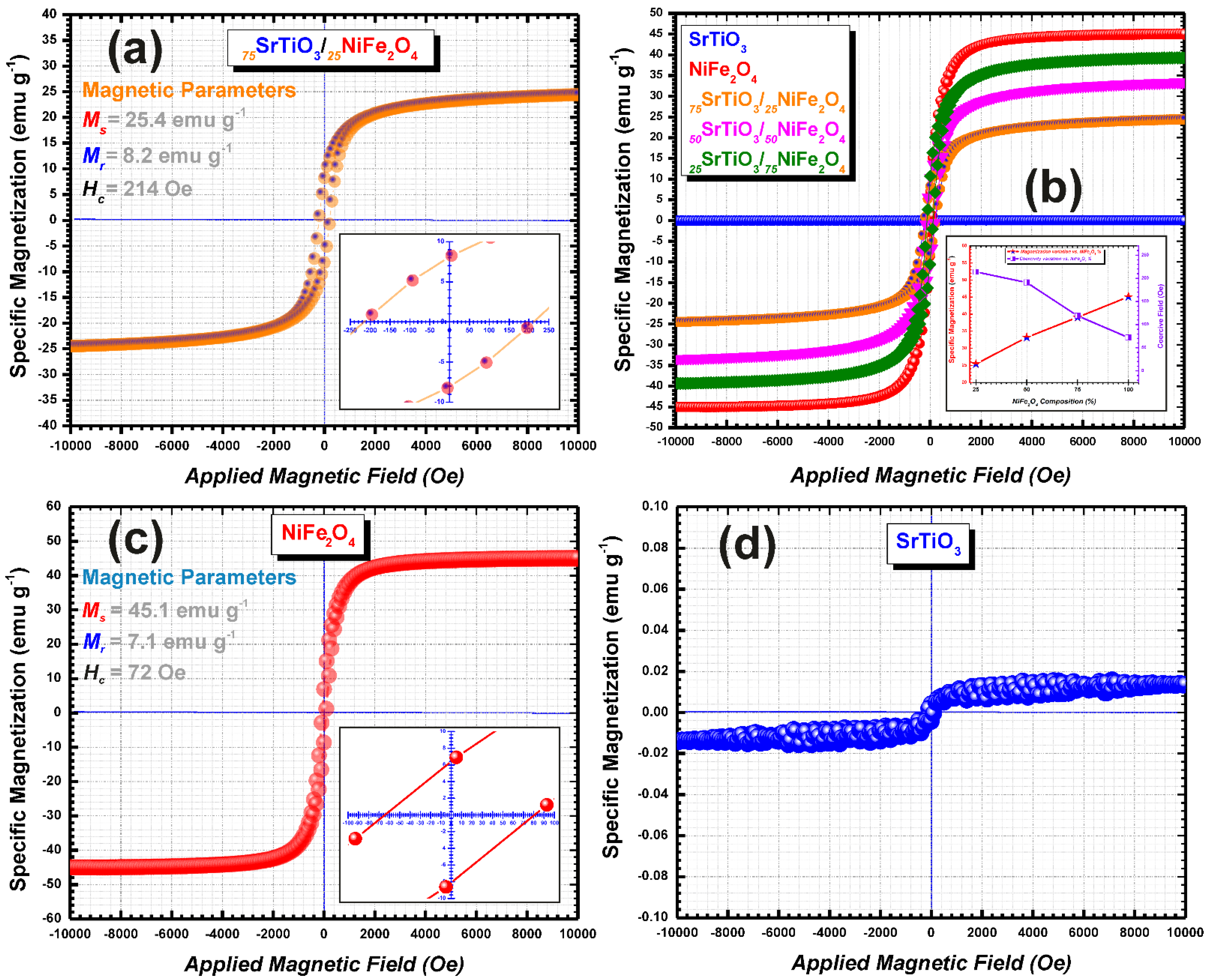
| Sample | Specific Magnetization (emu g−1) | Remanent Magnetization (emu g−1) | Coercive Field (Oe) | References |
|---|---|---|---|---|
| SrTiO3 | - | - | - | This Study |
| 75SrTiO3/25NiFe2O4 | 25.4 | 8.2 | 214 | This Study |
| 50SrTiO3/50NiFe2O4 | 33.2 | 10.5 | 191 | This Study |
| 25SrTiO3/75NiFe2O4 | 39.1 | 10.2 | 119 | This Study |
| NiFe2O4 | 45.1 | 7.1 | 72 | This Study |
| SrTiO3/NiFe2O4 porous nanotubes | 10 | n.a | n.a | [8] |
| SrTiO3/NiFe2O4 nanoparticle-in nanotubes | 18 | n.a | n.a | [8] |
| NiFe2O4 | 40 | n.a | n.a | [34] |
| 85% NiFe2O4 15% SrTiO3 | 23.3 | n.a | n.a | [34] |
Publisher’s Note: MDPI stays neutral with regard to jurisdictional claims in published maps and institutional affiliations. |
© 2021 by the authors. Licensee MDPI, Basel, Switzerland. This article is an open access article distributed under the terms and conditions of the Creative Commons Attribution (CC BY) license (https://creativecommons.org/licenses/by/4.0/).
Share and Cite
Baba-Ahmed, I.; Ghercă, D.; Iordan, A.-R.; Palamaru, M.N.; Mita, C.; Baghdad, R.; Ababei, G.; Lupu, N.; Benamar, M.A.; Abderrahmane, A.; et al. Sequential Synthesis Methodology Yielding Well-Defined Porous 75%SrTiO3/25%NiFe2O4 Nanocomposite. Nanomaterials 2022, 12, 138. https://doi.org/10.3390/nano12010138
Baba-Ahmed I, Ghercă D, Iordan A-R, Palamaru MN, Mita C, Baghdad R, Ababei G, Lupu N, Benamar MA, Abderrahmane A, et al. Sequential Synthesis Methodology Yielding Well-Defined Porous 75%SrTiO3/25%NiFe2O4 Nanocomposite. Nanomaterials. 2022; 12(1):138. https://doi.org/10.3390/nano12010138
Chicago/Turabian StyleBaba-Ahmed, Ilyes, Daniel Ghercă, Alexandra-Raluca Iordan, Mircea Nicolae Palamaru, Carmen Mita, Rachid Baghdad, Gabriel Ababei, Nicoleta Lupu, Mohamed Amine Benamar, Abdelkader Abderrahmane, and et al. 2022. "Sequential Synthesis Methodology Yielding Well-Defined Porous 75%SrTiO3/25%NiFe2O4 Nanocomposite" Nanomaterials 12, no. 1: 138. https://doi.org/10.3390/nano12010138
APA StyleBaba-Ahmed, I., Ghercă, D., Iordan, A.-R., Palamaru, M. N., Mita, C., Baghdad, R., Ababei, G., Lupu, N., Benamar, M. A., Abderrahmane, A., Roman, T., Bulai, G., Leontie, L., & Borhan, A. I. (2022). Sequential Synthesis Methodology Yielding Well-Defined Porous 75%SrTiO3/25%NiFe2O4 Nanocomposite. Nanomaterials, 12(1), 138. https://doi.org/10.3390/nano12010138