
Improved Solvothermal Synthesis of γ-Fe2O3 Magnetic Nanoparticles for SiO2 Coating


Abstract
:1. Introduction
2. Materials and Methods
2.1. Chemicals and Materials
2.2. Synthesis of Magnetic Iron-Oxide Nanoparticles by Co-Precipitation
2.3. Synthesis of Magnetic Iron-Oxide Nanoparticles by Solvothermal Method
2.4. Optimized Preparation of Silica Coated Magnetic Iron-Oxide Nanoparticles
2.5. MNP Physical Characterisation
2.5.1. Scanning Electron Microscopy (SEM)
2.5.2. Dynamic Light Scattering (DLS)
2.5.3. X-ray Diffraction (XRD)
2.5.4. Transmission Electron Microscopy (TEM)
2.5.5. X-ray Photoelectron Spectroscopy (XPS)
3. Results and Discussion
3.1. Magnetic Nanoparticles
3.1.1. Magnetic Nanoparticle Synthesis by Co-Precipitation
3.1.2. Magnetic Nanoparticle by Solvothermal Synthesis
3.1.3. Effect of Surfactants in Capping MNPs
3.2. Material Characterization
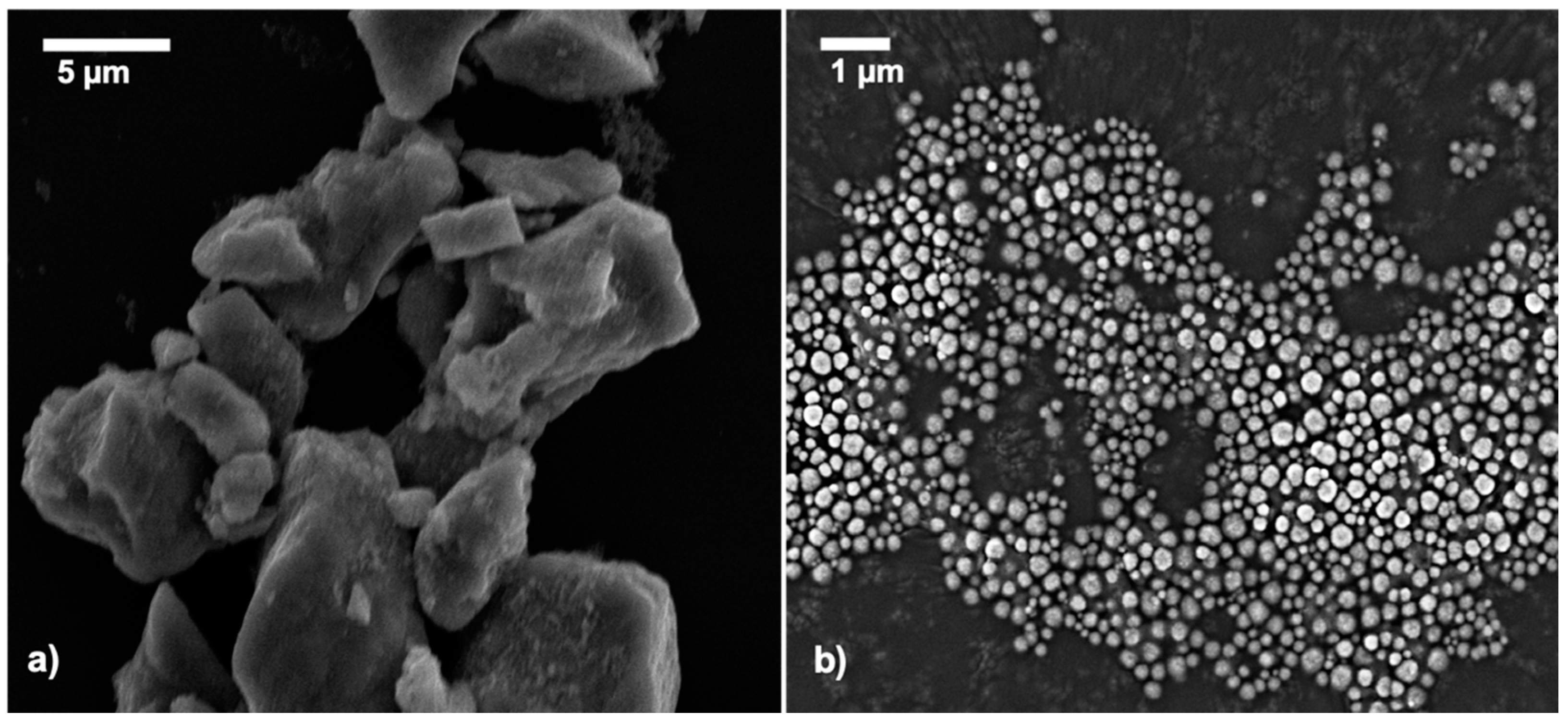
3.2.1. Surface Morphology Analysis
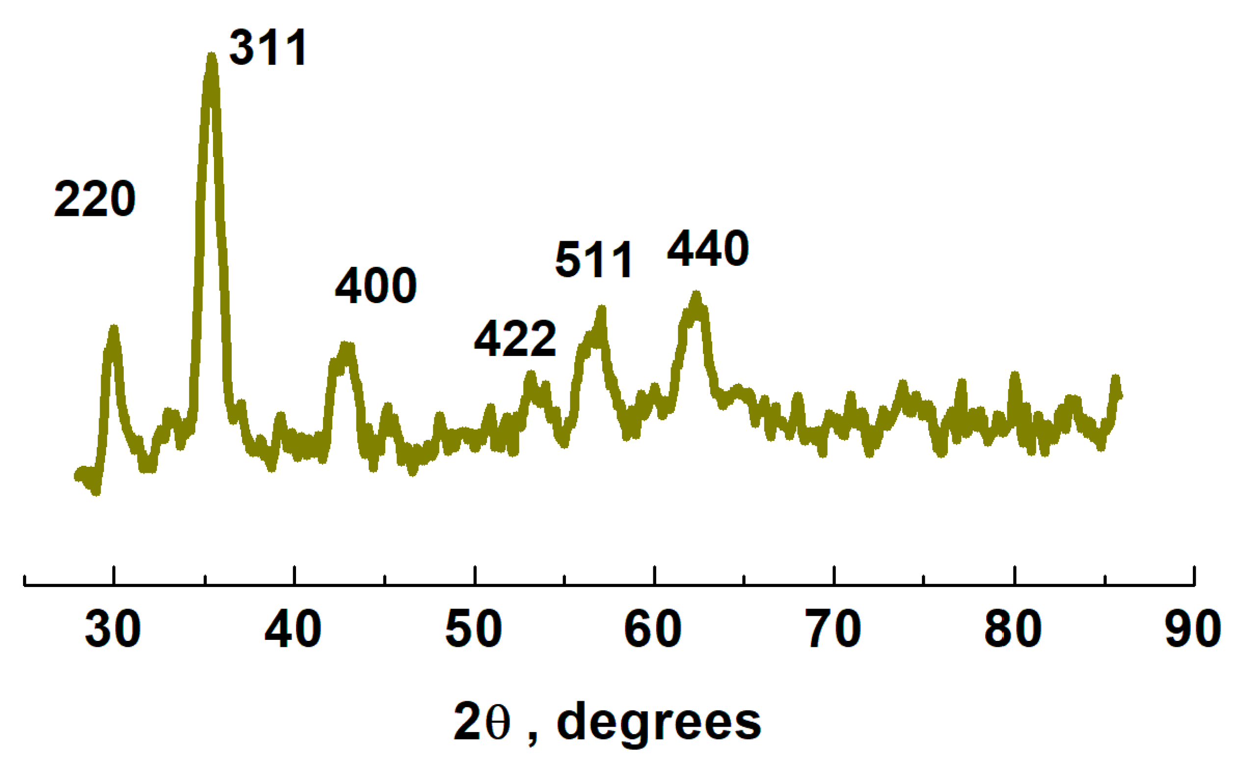
3.2.2. X-Ray Diffraction
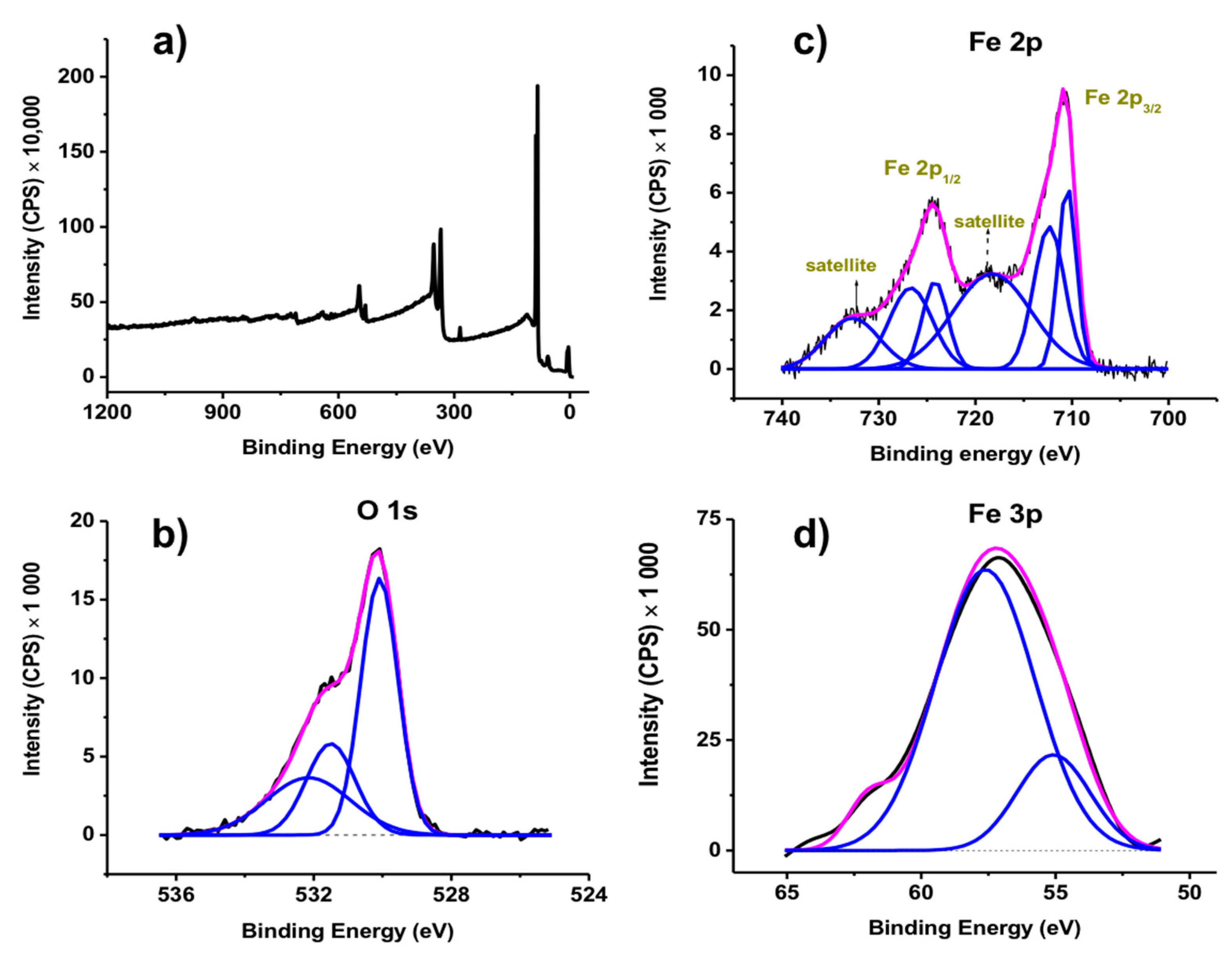
3.2.3. X-Ray Photoelectron Spectroscopy
3.3. Silica Coated Magnetic Nanoparticles (Sc-MNPs)
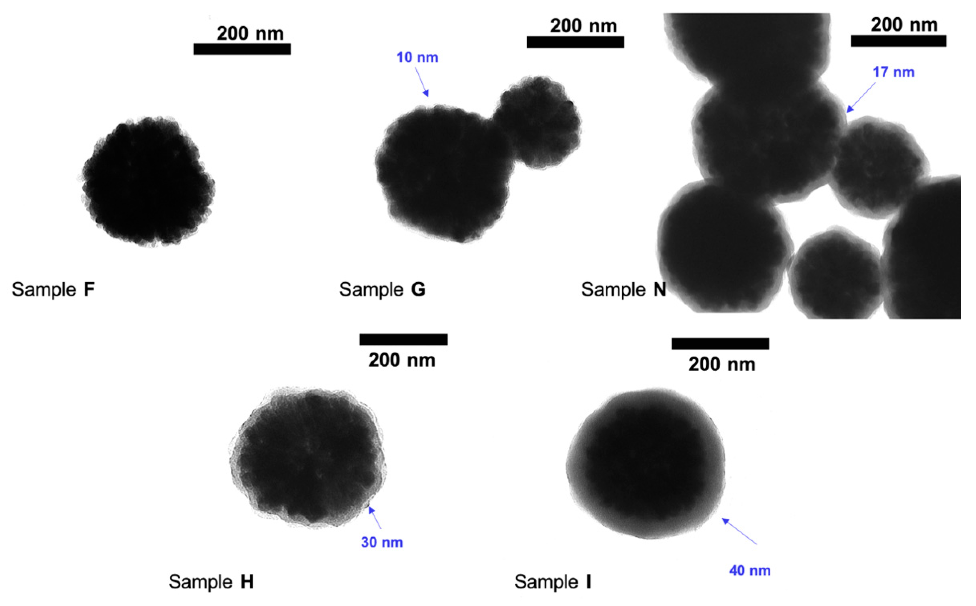
Surface Morphology Analysis
4. Conclusions
Supplementary Materials
Author Contributions
Funding
Acknowledgments
Conflicts of Interest
References
- Gloag, L.; Mehdipour, M.; Chen, D.; Tilley, R.D.; Gooding, J.J. Advances in the application of magnetic nanoparticles for sensing. Adv. Mater. 2019, 31, 1904385. [Google Scholar] [CrossRef]
- Canfarotta, F.; Piletsky, S.A. Engineered magnetic nanoparticles for biomedical applications. Adv. Healthc. Mater. 2014, 3, 160. [Google Scholar] [CrossRef] [PubMed]
- Wu, K.; Liu, D.S.J.; Saha, R.; Wang, J.-P. Magnetic nanoparticles in nanomedicine: A review of recent advances. Nanotechnology 2019, 30, 502003. [Google Scholar] [CrossRef] [Green Version]
- Williams, P.S.; Moore, L.R.; Joshi, P.; Goodin, M.; Zborowski, M.; Fleischman, A. Microfluidic chip for graduated magnetic separation of circulating tumor cells by their epithelial cell adhesion molecule expression and magnetic nanoparticle binding. J. Chromatogr. A 2021, 1637, 461823. [Google Scholar] [CrossRef] [PubMed]
- Wei, X.; Chen, K.; Guo, S.; Liu, W.; Zhao, X.-Z. Emerging microfluidic technologies for the detection of circulating tumor cells and fetal nucleated red blood cells. ACS Appl. Bio Mater. 2021, 4, 1140. [Google Scholar] [CrossRef]
- Kim, K.Y.; Chang, K.-A. Therapeutic potential of magnetic nanoparticle-based human adipose-derived stem cells in a mouse model of parkinson’s disease. Int. J. Mol. Sci. 2021, 22, 654. [Google Scholar] [CrossRef]
- Hou, Y.; Sun, Z.; Rao, W.; Liu, J. Nanoparticle-mediated cryosurgery for tumor therapy. Nanomedicine 2018, 14, 493. [Google Scholar] [CrossRef] [PubMed]
- Gaston, E.; Fraser, J.F.; Xu, Z.P.; Ta, H.T. Nano- and micro-materials in the treatment of internal bleeding and uncontrolled hemorrhage. Nanomedicine 2018, 14, 507. [Google Scholar] [CrossRef] [Green Version]
- Nabavinia, M.; Beltran-Huarac, J. Recent progress in iron oxide nanoparticles as therapeutic magnetic agents for cancer treatment and tissue engineering. ACS Appl. Bio Mater. 2020, 3, 8172. [Google Scholar] [CrossRef]
- Peralta, M.E.; Jadhav, S.A.; Magnacca, G.; Scalarone, D.; Martire, D.O.; Parolo, M.E.; Carlos, L. Synthesis and in vitro testing of thermoresponsive polymer-grafted core-shell magnetic mesoporous silica nanoparticles for efficient controlled and targeted drug delivery. J. Colloid Interface Sci. 2019, 544, 198. [Google Scholar] [CrossRef]
- Ulbrich, K.; Hola, K.; Subr, V.; Bakandritsos, A.; Tucek, J.; Zboril, R. Targeted drug delivery with polymers and magnetic nanoparticles: Covalent and noncovalent approaches, release control, and clinical studies. Chem. Rev. 2016, 116, 5338. [Google Scholar] [CrossRef]
- Magro, M.; Martinello, T.; Bonaiuto, E.; Gomiero, C.; Baratella, D.; Zoppellaro, G.; Cozza, G.; Patruno, M.; Zboril, R.; Vianello, F. Covalently bound DNA on naked iron oxide nanoparticles: Intelligent colloidal nano-vector for cell transfection. Biochim. Biophys. Acta Gen. Subj. 2017, 1861, 2802. [Google Scholar] [CrossRef]
- Dallet, L.; Stanicki, D.; Voisin, P.; Miraux, S.; Ribot, E.J. Micron-sized iron oxide particles for both mri cell tracking and magnetic fluid hyperthermia treatment. Sci. Rep. 2021, 11, 3286. [Google Scholar] [CrossRef] [PubMed]
- Naud, C.; Thebault, C.; Carriere, M.; Hou, Y.; Morel, R.; Berger, F.o.; Dieny, B.; Joisten, H. Cancer treatment by magneto-mechanical effect of particles, a review. Nanoscale Adv. 2020, 2, 3632. [Google Scholar] [CrossRef]
- Jeon, M.; Halbert, M.V.; Stephen, Z.R.; Zhang, M. Iron oxide nanoparticles as t1 contrast agents for magnetic resonance imaging: Fundamentals, challenges, applications, and prospectives. Adv. Mater. 2020, 33, e1906539. [Google Scholar] [CrossRef]
- Wierucka, M.; Biziuk, M. Application of magnetic nanoparticles for magnetic solid-phase extraction in preparing biological, environmental and food samples. Trends Analyt. Chem. 2014, 59, 50. [Google Scholar] [CrossRef]
- Baron, D.; Dolanska, P.; Medrikova, Z.; Zboril, R.; Petr, J. Online stacking of carboxylated magnetite core-shell nanoparticles in capillary electrophoresis. J. Sep. Sci. 2017, 40, 2482. [Google Scholar] [CrossRef] [PubMed]
- Garcia-Cruz, A.; Cowen, T.; Voorhaar, A.; Piletska, E.; Piletsky, S.A. Molecularly imprinted nanoparticles-based assay (mina)–detection of leukotrienes and insulin. Analyst 2020, 145, 4224. [Google Scholar] [CrossRef]
- Esen, C.; Czulak, J.; Cowen, T.; Piletska, E.; Piletsky, S.A. Highly efficient abiotic assay formats for methyl parathion: Molecularly imprinted polymer nanoparticle assay as an alternative to enzyme-linked immunosorbent assay. Anal. Chem. 2019, 91, 958. [Google Scholar] [CrossRef] [PubMed]
- Wu, K.; Saha, R.; Su, D.; Krishna, V.D.; Liu, J.; Cheeran, M.C.J.; Wang, J.-P. Magnetic-nanosensor-based virus and pathogen detection strategies before and during covid-19. ACS Appl. Nano Mater. 2020, 3, 9560. [Google Scholar] [CrossRef]
- Zhong, J.; Rosch, E.L.; Viereck, T.; Schilling, M.; Ludwig, F. Toward rapid and sensitive detection of sars-cov-2 with functionalized magnetic nanoparticles. ACS Sens. 2021, 6, 976. [Google Scholar] [CrossRef]
- Bao, Y.; Wen, T.; Samia, A.C.S.; Khandhar, A.; Krishnan, K.M. Magnetic nanoparticles: Material engineering and emerging applications in lithography and biomedicine. J. Mater. Sci. 2016, 51, 513. [Google Scholar] [CrossRef] [PubMed] [Green Version]
- Shahidi, S. Magnetic nanoparticles application in the textile industry—A review. J. Ind. Text. 2019, 50, 970. [Google Scholar] [CrossRef]
- Wang, Z.; Zhang, Z.; Yan, R.; Fu, X.; Wang, G.; Wang, Y.; Li, Z.; Zhang, X.; Hou, J. Facile fabrication of snowman-like magnetic molecularly imprinted polymer microspheres for bisphenol a via one-step pickering emulsion polymerization. React. Funct. Polym. 2021, 164, 104911. [Google Scholar] [CrossRef]
- Tavallaie, R.; McCarroll, J.; Le Grand, M.; Ariotti, N.; Schuhmann, W.; Bakker, E.; Tilley, R.D.; Hibbert, D.B.; Kavallaris, M.; Gooding, J.J. Nucleic acid hybridization on an electrically reconfigurable network of gold-coated magnetic nanoparticles enables microrna detection in blood. Nat. Nanotechnol. 2018, 13, 1066. [Google Scholar] [CrossRef]
- Trifonov, A.; Stemmer, A.; Tel-Vered, R. Carbon-coated magnetic nanoparticles as a removable protection layer extending the operation lifetime of bilirubin oxidase-based bioelectrode. Bioelectrochemistry 2021, 137, 107640. [Google Scholar] [CrossRef]
- Refaat, D.; Aggour, M.G.; Farghali, A.A.; Mahajan, R.; Wiklander, J.G.; Nicholls, I.A.; Piletsky, S.A. Strategies for molecular imprinting and the evolution of mip nanoparticles as plastic antibodies-synthesis and applications. Int. J. Mol. Sci. 2019, 20, 6304. [Google Scholar] [CrossRef] [Green Version]
- Mahajan, R.; Rouhi, M.; Shinde, S.; Bedwell, T.; Incel, A.; Mavliutova, L.; Piletsky, S.; Nicholls, I.A.; Sellergren, B.R. Highly efficient synthesis and assay of protein-imprinted nanogels by using magnetic templates. Angew. Chem. Int. Ed. Engl. 2019, 58, 727. [Google Scholar] [CrossRef] [Green Version]
- Piletsky, S.S.; Cass, A.E.G.; Piletska, E.V.; Czulak, J.; Piletsky, S.A. A novel assay format as an alternative to elisa: Mina test for biotin. ChemNanoMat 2018, 4, 1214. [Google Scholar] [CrossRef]
- Rossi, L.M.; Costa, N.J.S.; Silva, F.P.; Wojcieszak, R. Magnetic nanomaterials in catalysis: Advanced catalysts for magnetic separation and beyond. Green Chem. 2014, 16, 2906. [Google Scholar] [CrossRef]
- Lorenz, P.; Luchs, T.; Hirsch, A. Molecular solar thermal batteries through combination of magnetic nanoparticle catalysts and tailored norbornadiene photoswitches. Chemistry 2021, 27, 4993. [Google Scholar] [CrossRef] [PubMed]
- Zambrzycki, C.; Shao, R.; Misra, A.; Streb, C.; Herr, U.; Güttel, R. Iron based core-shell structures as versatile materials: Magnetic support and solid catalyst. Catalysts 2021, 11, 72. [Google Scholar] [CrossRef]
- Akbarzadeh, A.; Samiei, M.; Davaran, S. Magnetic nanoparticles: Preparation, physical properties, and applications in biomedicine. Nanoscale Res. Lett. 2012, 7, 144. [Google Scholar] [CrossRef] [PubMed] [Green Version]
- Lu, A.-H.; Salabas, E.L.; Schüth, F. Magnetic nanoparticles: Synthesis, protection, functionalization, and application. Angew. Chem. Int. Ed. Engl. 2007, 46, 1222. [Google Scholar] [CrossRef]
- Pérez, N.; Moya, C.; Tartaj, P.; Labarta, A.; Batlle, X. Aggregation state and magnetic properties of magnetite nanoparticles controlled by an optimized silica coating. J. Appl. Phys. 2017, 121, 044304. [Google Scholar] [CrossRef]
- Gul, S.; Khan, S.B.; Rehman, I.U.; Khan, M.A.; Khan, M.I. A comprehensive review of magnetic nanomaterials modern day theranostics. Front. Mater. 2019, 6, 179. [Google Scholar] [CrossRef] [Green Version]
- Guardia, P.; Perez, N.; Labarta, A.; Batlle, X. Controlled synthesis of iron oxide nanoparticles over a wide size range. Langmuir 2010, 26, 5843. [Google Scholar] [CrossRef]
- Kim, H.-J.; Kim, S.H.; Kim, H.-M.; Kim, Y.S.; Oh, J.-M. Surface roughness effect on the cellular uptake of layered double hydroxide nanoparticles. Appl. Clay Sci. 2021, 202, 105992. [Google Scholar] [CrossRef]
- Tripathy, A.; Nine, M.J.; Silva, F.S. Biosensing platform on ferrite magnetic nanoparticle: Synthesis, functionalization, mechanism and applications. Adv. Colloid Interface Sci. 2021, 290, 102380. [Google Scholar] [CrossRef]
- Rouhi, M.; Lakouraj, M.M.; Baghayeri, M.; Hasantabar, V. Novel conductive magnetic nanocomposite based on poly (indole-co-thiophene) as a hemoglobin diagnostic biosensor: Synthesis, characterization and physical properties. Int. J. Polym. Mater. 2016, 66, 12. [Google Scholar] [CrossRef]
- Yan, A.; Liu, X.; Qiu, G.; Wu, H.; Yi, R.; Zhang, N.; Xu, J. Solvothermal synthesis and characterization of size-controlled Fe3O4 nanoparticles. J. Alloys Compd. 2008, 458, 487. [Google Scholar] [CrossRef]
- Huang, Y.; Zhang, L.; Huan, W.; Liang, X.; Liu, X.; Yang, Y. A study on synthesis and properties of Fe3O4 nanoparticles by solvothermal method. Glass Phys. Chem. 2010, 36, 325. [Google Scholar] [CrossRef]
- Liu, B.; Wang, D.; Huang, W.; Yao, A.; Kamitakahara, M.; Ioku, K. Preparation of magnetite nanoparticles coated with silica via a sol-gel approach. J. Ceram. Soc. Jpn. 2007, 115, 877. [Google Scholar] [CrossRef] [Green Version]
- Xu, J.; Sun, J.; Wang, Y.; Sheng, J.; Wang, F.; Sun, M. Application of iron magnetic nanoparticles in protein immobilization. Molecules 2014, 19, 11465–11486. [Google Scholar] [CrossRef]
- Majidi, S.; Sehrig, F.Z.; Farkhani, S.M.; Goloujeh, M.S.; Akbarzadeh, A. Current methods for synthesis of magnetic nanoparticles. Artif. Cells Nanomed. Biotechnol. 2016, 44, 722. [Google Scholar] [CrossRef] [PubMed]
- Wu, W.; He, Q.; Jiang, C. Magnetic iron oxide nanoparticles: Synthesis and surface functionalization strategies. Nanoscale Res. Lett. 2008, 3, 397. [Google Scholar] [CrossRef] [PubMed] [Green Version]
- Movlaee, K.; Ganjali, M.R.; Norouzi, P.; Neri, G. Iron-based nanomaterials/graphene composites for advanced electrochemical sensors. Nanomaterials 2017, 7, 406. [Google Scholar] [CrossRef] [Green Version]
- Kozakova, Z.; Kuritka, I.; Kazantseva, N.E.; Babayan, V.; Pastorek, M.; Machovsky, M.; Bazant, P.; Saha, P. The formation mechanism of iron oxide nanoparticles within the microwave-assisted solvothermal synthesis and its correlation with the structural and magnetic properties. Dalton Trans. 2015, 44, 21099. [Google Scholar] [CrossRef] [Green Version]
- Guo, W.; Sun, Y.W.; Luo, G.S.; Wang, Y.J. Interaction of peg with ionic surfactant sds to form template for mesoporous material. Colloids Surf. A Physicochem. Eng. Asp. 2005, 252, 71. [Google Scholar] [CrossRef]
- Zhang, Y.; Li, L.; Ma, W.; Zhang, Y.; Yu, M.; Guo, J.; Lu, H.; Wang, C. Two-in-one strategy for effective enrichment of phosphopeptides using magnetic mesoporous gamma-Fe2O3 nanocrystal clusters. ACS Appl. Mater. Interfaces 2013, 5, 614. [Google Scholar] [CrossRef]
- Yamashita, T.; Hayes, P. Analysis of xps spectra of Fe2+ and Fe3+ ions in oxide materials. Appl. Surf. Sci. 2008, 254, 2441. [Google Scholar] [CrossRef]
- Figueroa, A.I.; Moya, C.; Bartolome, J.; Bartolome, F.; Garcia, L.M.; Perez, N.; Labarta, A.; Batlle, X. Sio2 coating effects in the magnetic anisotropy of Fe3−xO4 nanoparticles suitable for bio-applications. Nanotechnology 2013, 24, 155705. [Google Scholar] [CrossRef] [Green Version]
- Pham, X.-H.; Hahm, E.; Kim, H.-M.; Son, B.S.; Jo, A.; An, J.; Thi, T.A.T.; Nguyen, D.Q.; Jun, B.-H. Silica-coated magnetic iron oxide nanoparticles grafted onto graphene oxide for protein isolation. Nanomaterials 2020, 10, 117. [Google Scholar] [CrossRef] [PubMed] [Green Version]
- Joshi, D.P.; Pant, G.; Arora, N.; Nainwal, S. Effect of solvents on morphology, magnetic and dielectric properties of (alpha-fe2o3@sio2) core-shell nanoparticles. Heliyon 2017, 3, 253. [Google Scholar] [CrossRef] [PubMed] [Green Version]
- Deng, Y.-H.; Wang, C.-C.; Hu, J.-H.; Yang, W.-L.; Fu, S.-K. Investigation of formation of silica-coated magnetite nanoparticles via sol–gel approach. Colloids Surf. A Physicochem. Eng. Asp. 2005, 262, 87. [Google Scholar] [CrossRef]
- Han, H.; Johnson, A.; Kaczor, J.; Kaur, M.; Paszczynski, A.; Qiang, Y. Silica coated magnetic nanoparticles for separation of nuclear acidic waste. J. Appl. Phys. 2010, 107, 09B520. [Google Scholar] [CrossRef]
- Kashanian, F.; Kokkinis, G.; Bernardi, J.; Zand, M.R.; Shamloo, A.; Giouroudi, I. A novel magnetic microfluidic platform for on-chip separation of 3 types of silica coated magnetic nanoparticles (Fe3O4@SiO2). Sens. Actuators A Phys. 2018, 270, 223. [Google Scholar] [CrossRef]
- Elmobarak, W.F.; Almomani, F. Functionalization of silica-coated magnetic nanoparticles as powerful demulsifier to recover oil from oil-in-water emulsion. Chemosphere 2021, 279, 130360. [Google Scholar] [CrossRef] [PubMed]
- Antarnusa, G.; Suharyadi, E. A synthesis of polyethylene glycol (peg)-coated magnetite Fe3O4 nanoparticles and their characteristics for enhancement of biosensor. Mater. Res. Express. 2020, 7, 056103. [Google Scholar] [CrossRef]


| Sample No. | MNP Concentration (mg/mL) | TEOS Concentration (M) | Catalyst Concentration (M) | Ethanolic Solution (%, v/v) EtOH in H2O |
|---|---|---|---|---|
| A | 1 | 0.05 | 0.10 | H2O |
| B | 1 | 0.05 | 0.10 | EtOH |
| C | 1 | 0.05 | 0.10 | 20 |
| D | 1 | 0.05 | 0.10 | 40 |
| E | 1 | 0.05 | 0.10 | 60 |
| F | 1 | 0.05 | 0.01 | 80 |
| G | 1 | 0.05 | 0.05 | 80 |
| H | 1 | 0.05 | 0.25 | 80 |
| I | 1 | 0.05 | 0.50 | 80 |
| J | 1 | 0.01 | 0.10 | 80 |
| K | 1 | 0.10 | 0.10 | 80 |
| L | 1 | 0.25 | 0.10 | 80 |
| M | 1 | 0.50 | 0.10 | 80 |
| N | 1 | 0.05 | 0.10 | 80 |
| O | 0.5 | 0.10 | 0.10 | 80 |
| P | 0.1 | 0.10 | 0.10 | 80 |
| Sample Name | Batch No | Z Average (nm) | PDI | ZP (mV) |
|---|---|---|---|---|
| nMNPs | B1 | 324 ± 2.99 | 0.192 ± 0.020 | −22.60 ± 0.30 |
| B2 | 335 ± 2.26 | 0.200 ± 0.009 | −06.70 ± 0.33 | |
| B3 | 329 ± 2.27 | 0.207 ± 0.007 | −10.70 ± 0.25 | |
| sMNPs | B1 | 291 ± 1.51 | 0.138 ± 0.005 | 03.52 ± 1.74 |
| B2 | 283 ± 9.01 | 0.166 ± 0.037 | 17.00 ± 1.77 | |
| B3 | 307 ± 11.4 | 0.223 ± 0.024 | 07.25 ± 1.70 | |
| pMNPs | B1 | 173 ± 1.73 | 0.089 ± 0.025 | 14.00 ± 1.30 |
| B2 | 300 ± 4.66 | 0.157 ± 0.035 | 17.01 ± 0.85 | |
| B3 | 215 ± 6.78 | 0.111 ± 0.019 | 13.03 ± 2.49 | |
| spMNPs | B1 | 261 ± 15.0 | 0.229 ± 0.027 | 37.70 ± 0.12 |
| B2 | 263 ± 9.30 | 0.166 ± 0.048 | 39.70 ± 3.44 | |
| B3 | 247 ± 9.06 | 0.160 ± 0.023 | 41.00 ± 3.59 |
Publisher’s Note: MDPI stays neutral with regard to jurisdictional claims in published maps and institutional affiliations. |
© 2021 by the authors. Licensee MDPI, Basel, Switzerland. This article is an open access article distributed under the terms and conditions of the Creative Commons Attribution (CC BY) license (https://creativecommons.org/licenses/by/4.0/).
Share and Cite
Mahajan, R.; Suriyanarayanan, S.; Nicholls, I.A. Improved Solvothermal Synthesis of γ-Fe2O3 Magnetic Nanoparticles for SiO2 Coating. Nanomaterials 2021, 11, 1889. https://doi.org/10.3390/nano11081889
Mahajan R, Suriyanarayanan S, Nicholls IA. Improved Solvothermal Synthesis of γ-Fe2O3 Magnetic Nanoparticles for SiO2 Coating. Nanomaterials. 2021; 11(8):1889. https://doi.org/10.3390/nano11081889
Chicago/Turabian StyleMahajan, Rashmi, Subramanian Suriyanarayanan, and Ian A. Nicholls. 2021. "Improved Solvothermal Synthesis of γ-Fe2O3 Magnetic Nanoparticles for SiO2 Coating" Nanomaterials 11, no. 8: 1889. https://doi.org/10.3390/nano11081889
APA StyleMahajan, R., Suriyanarayanan, S., & Nicholls, I. A. (2021). Improved Solvothermal Synthesis of γ-Fe2O3 Magnetic Nanoparticles for SiO2 Coating. Nanomaterials, 11(8), 1889. https://doi.org/10.3390/nano11081889