Article

The Halogenation Effects of Electron Acceptor ITIC for Organic Photovoltaic Nano-Heterojunctions

1
Department of Applied Physics, Lanzhou University of Technology, Lanzhou 730050, China
2
Department of Physics, Lanzhou City University, Lanzhou 730070, China
3
School of Materials Science and Engineering, Lanzhou University of Technology, Lanzhou 730050, China
4
College of Physics and Electronic Engineering, Northwest Normal University, Lanzhou 730070, China
*
Author to whom correspondence should be addressed.
Nanomaterials 2021, 11(12), 3417; https://doi.org/10.3390/nano11123417
Submission received: 26 October 2021 / Revised: 8 December 2021 / Accepted: 12 December 2021 / Published: 16 December 2021
(This article belongs to the Section Theory and Simulation of Nanostructures)

Abstract

:
Molecular engineering plays a critical role in the development of electron donor and acceptor materials for improving power conversion efficiency (PCE) of organic photovoltaics (OPVs). The halogenated acceptor materials in OPVs have shown high PCE. Here, to investigate the halogenation mechanism and the effects on OPV performances, based on the density functional theory calculations with the optimally tuned screened range-separated hybrid functional and the consideration of solid polarization effects, we addressed the halogenation effects of acceptor ITIC, which were modeled by bis-substituted ITIC with halogen and coded as IT-2X (X = F, Cl, Br), and PBDB-T:ITIC, PBDB-T:IT-2X (X = F, Cl, Br) complexes on their geometries, electronic structures, excitations, electrostatic potentials, and the rate constants of charge transfer, exciton dissociation (ED), and charge recombination processes at the heterojunction interface. The results indicated that halogenation of ITIC slightly affects molecular geometric structures, energy levels, optical absorption spectra, exciton binding energies, and excitation properties. However, the halogenation of ITIC significantly enlarges the electrostatic potential difference between the electron acceptor and donor PBDB-T with the order from fluorination and chlorination to bromination. The halogenation also increases the transferred charges of CT states for the complexes. Meanwhile, the halogenation effects on CT energies and electron process rates depend on different haloid elements. No matter which kinds of haloid elements were introduced in the halogenation of acceptors, the ED is always efficient in these OPV devices. This work provides an understanding of the halogenation mechanism, and is also conducive to the designing of novel materials with the aid of the halogenation strategy.

1. Introduction

Organic photovoltaics (OPVs) have received extensive attention in recent years due to their light weight, low cost, semitransparency, flexibility, etc. The design and development of high-performance OPV devices are of great significance to solving the energy crisis [1,2,3]. Up to now, the power conversion efficiency (PCE) record of OPVs was over 18% [4,5,6,7]. Most of the electron processes for OPV power conversion happen in the active layer which is composed of both electron donor and acceptor materials. As the core of the OPV device, the changing active layer materials can tune photovoltaic performances [8,9]. In the past few years, the design and development of new electron donor and acceptor materials for OPV active layer have promoted the rapid improvement of PCE. Fullerene and its derivatives were usually used as electron acceptor materials due to their high electron affinity and electron mobility. However, their shortcomings of fullerenes limit their extensive application in OPV, including for complicated manufacturing processes, poor absorption in the visible and infrared region, and scare energy level adjustability. Non-fullerenes acceptors (NFAs) have many advantages over fullerenes, such as tunable energy levels and high molar absorption coefficients, resulting in a situation where NFAs have gradually replaced fullerenes as electron acceptors in OPV.
Backbone modification, side-chain engineering, and end-group substitution are common strategies for designing new electron donor and acceptor materials of OPV. Among these methods, halogen substitution has been shown to be effective for improving OPV performance. A fluorine atom is a type of halogen atom with the strongest electronegativity (3.98) and the smallest size (the van der Waals radius of 147 pm), which can effectively adjust the π-electron properties without causing unexpected steric hindrance. Experiments also proved that some chlorinated and brominated systems showed similar or stronger capability for adjusting π-conjugated electronic properties [10,11,12], which were caused by the larger dipole moments of C-Cl and C-Br bonds than that of a C-F bond [13]. Therefore, it is extremely important to research the influence of halogenation on materials’ physical properties and to explore the relationship between physical properties and photovoltaic performance.
Developing donor or acceptor materials by halogenation improved OPV performance [14,15]. Pei et al. found that the chlorinated backbone of a isoindigo-based polymer donor and acceptor (PC71BM) showed an appropriate degree of phase separation, reduced film crystallinity, and improved OPV performance (which was ascribed to the donor molecular stacking orientation [16]). Forrest et al. synthesized the BT-CIC by chlorinating BT-IC, and found that the chlorination caused the improved planarity of molecular geometry and significant red-shift of absorption spectrum (about 60 nm) with the 1.33 eV bandgap, resulting in an external quantum efficiency (EQE) of 75% in the wavelength region of 630–850 nm and of more than 11% of PCE [17]. Yan et al. reported that the C8-ITCC-Cl NFA which is chlorinated thienyls in C8-ITCC increased PCE from 10.8% to 12.7%, and found the chlorination of NFA induced the stronger noncovalent interactions which is favorable to improve the layered π-π stacking [18]. This highlighted the potential of halogenated thiophene end groups in NFA to improve PCE. Yasuda et al. designed a new type of NFA BDT-ID-X (X = F, Cl, Br, I), and found that subtle halogenations at the NFA end group can significantly affect the photoelectronic properties and film morphology [12]. Among them, Br and I substitutions can drastically reduce the surface free energies of donor/acceptor interfaces, forming fine bulk heterojunction (BHJ) for OPV. Hou et al. investigated the fluorinated electron donor PBDB-TF, fluorinated NFA BTP-4F, and chlorinated BTP-4Cl, and found that the halogenation can increase open-circuit voltage (VOC) and PCE (15.6% and 16.5%, respectively) by reducing energy losses [19]. The corresponding energy losses are 0.60 eV and 0.53 eV, and the non-radiative energy losses are 0.25 eV and 0.21 eV, respectively, which are lower than those of most reported OPVs. Cao et al. designed the NFA BDTBO-4F and BDTBO-4Cl through halogenation strategy and adopted PM6 as electron donor for fabricating OPV. Hole transfer at donor/acceptor interfaces was still efficient though the highest occupied molecular orbital (HOMO) offsets between the donor and acceptor are smaller than 0.1 eV, and the PM6:BDTBO-4F device exhibited a low charge recombination (CR) rate, high charge mobility, and suitable phase separation [20]. Also, halogenation at different substitution positions can cause changes in π-π stacking distance, supermolecular interaction, miscibility, and steric hindrance, which affect the aggregation behavior in blends [21,22,23,24,25,26,27].
In addition to experimental studies, many theoretical works were also conducted to understand the halogenation effects on OPV material properties [28,29]. Bredas et al. compared the electronic properties of polymers PBT4T-2OD and PffBT4T-2OD for understanding the correlation between solution temperature-dependent aggregation and solid-state stacking, and found that fluorination can enhance the planarity of the donor polymer backbone and increase the interaction among polymers, promoting molecule packing order for higher PCE [30]. Koehler et al. found that fluorination tends to reduce exciton binding energy (Eexb), improve exciton dissociation (ED) efficiency, promote carrier mobility, restrict bimolecular CR, and reduce the resistance of bulk heterojunction [31]. Hou et al. reported that halogenation generates a larger difference of molecular surface average electrostatic potential (ESP) between the electron donor and acceptor [32]. Therefore, it induces a stronger intermolecular electric field at donor/acceptor interface which can increase ED efficiency and then enlarge the short-circuit current density (Jsc) [33]. Based on the designed compounds, Mahmood et al. found that the fluorination of the end-groups increased the dipole moment difference between the ground state and the first excited state with the reduced Eexb, and also enhanced electronic coupling for charge transport [34]. Our previous work indicated that electron donor halogenation can remarkably influence energy level alignment at heterojunction interfaces, and the improved PCE induced by donor halogenation can be mainly ascribed to the increased charge transfer (CT) excitation energies and suppression of CR processes [35].
The ITIC is a superstar of NFA and has been received extensive research attention since it inaugurated a new era of OPV [31,36,37]. The A-D-A type molecular architecture of ITIC, containing large planar conjugated backbone and strong electron-withdrawing end groups, promotes the π-electron delocalization and intramolecular charge transfer/transport. The study of the fluorinated and chlorinated ITIC by Hou et al. found that chlorination has a stronger ability to stabilize molecular energy levels and broaden the absorption spectrum than fluorination, and the position of halogen atoms can affect the crystallinity of halogenated ITIC [38,39]. Among the OPV devices based on bis-substituted halogenation (F, Cl, Br) of ITIC as NFAs and PBDB-T as electron donor, the fluorinated system generated the largest Jsc, while the brominated system exhibited the highest FF (about 0.71) with a small amount of agglomeration area in the blended film, leading to the reduction of EQE and Jsc [40].
Overall, why halogenation of active layer materials usually improve OPV performance can be qualitatively attributed to two aspects. On the one hand, halogenation tunes electronic structures and excitation properties, including stabilizing molecular energy levels, enhancement of light absorption, increasing EQE and, thus Jsc, and reducing energy losses and then increasing Voc [41]. On the other hand, halogenation improves aggregation, packing order, crystallization and film morphologies due to the strengthened intramolecular or intermolecular interaction, achieving effective ED and charge transfer/transport [24,40,42,43,44]. However, the fundamental understanding of halogenation mechanisms, including the effects on electron processes at interface and OPV work principles, still remains uninvestigated. Here, to investigate acceptor halogenation effects, we selected PBDB-T:ITIC and PBDB-T:IT-2X (X = F, Cl, Br) as the model systems whose molecular structures are shown in Figure 1, and analyzed the molecular geometries, electronic structures, optical properties, excitation properties, ESP and the kinetics of electron processes at the heterojunction interfaces.

2. Computational Methods

The molecular structures of PBDB-T, ITIC and IT-2X (X = F, Cl, Br) were optimized at the level of ωB97XD/6-31G(d,p) [45,46]. Two repeat units were considered as the molecular structure of polymer donor PBDB-T in calculations, since the calculated frontier molecular orbitals (MOs) of polymer donor D18 whose molecular structure is similar to that of PBDB-T indicated that the frontier MOs are mainly localized on two repeat units [47]. Based upon the optimized molecular structures of PBDB-T, ITIC and IT-2X (X = F, Cl, Br), the PBDB-T:ITIC and PBDB-T:IT-2X (X = F, Cl, Br) heterojunction interfaces were modeled by using their complexes, in which the face-on configuration was considered due to the experimental results and the promoted π-π stacking [48]. To reduce the computational cost, the alkyl chains (-C2H5, -C4H9 in the polymer donor and -C6H13 in the acceptors) in the complexes were substituted with -CH3, since the side chain only affects the active layer morphology and does not affect other properties [49]; this simplification has been widely used in other works [31,50,51]. The constructed PBDB-T:ITIC and PBDB-T:IT-2X (X = F, Cl, Br) complexes were further optimized using ωB97XD/6-31G(d,p) methods. The excitation properties of donor and acceptor molecules, as well as the PBDB-T:ITIC and PBDB-T:IT-2X (X = F, Cl, Br) complexes, were calculated using time-dependent density functional theory (TDDFT) methods. The solid environment of OPV devices was simulated by self-consistent reaction field (SCRF) method with polarization continuum model (PCM) [52], requiring the static and dynamic dielectric constant (εs and εd) to describe the polarization effects of solid environment. The εs and εd of models are 3.5 and 3.3, respectively.
TDDFT results heavily depend on the selected DFT functional. The long range corrected hybrid functional with the optimally tuned range separation parameter ω exhibited excellent performance in calculations of CT excitation. However, the optimally tuned range separation parameter in solid phase for long range corrected hybrid functional is quite small. Zheng et al. presented the optimally tuned screened range-separated hybrid (OT-SRSH) functional method, and gave the reasonable physical interpretation for optimally tuned range separation parameter [53]. In this work, the OT-SRSH functional method was applied with LC-PBE functional and 6-31G(d,p) basis sets for excitations, ESP and electronic coupling calculations. The following methods were adopted for optimally tuning ω [35,54,55]:
E 1 ω = | E D H O M O ω + E D + ω E D ω |   +   | E A H O M O ω + E A + ω E A ω | E 2 ω = | E D H O M O ω + E D + ω E D ω |   +   | E A H O M O ω + E A ω E A ω | E ω = E 1 ω + E 2 ω
where E D H O M O ω , E A H O M O ω , E A H O M O ω are the HOMO level to the neutral donor, acceptor at neutral state and acceptor at anion state, respectively. The E D + ω , E A + ω , E A ω are the single-point energy of the donor at cation state, acceptor at cation state, and acceptor at anion state, respectively. The E D ω and E A ω are the neutral state energy of the donor and acceptor, respectively. The optimally tuned ω is 0.155, 0.155, 0.167, 0.144, 0.155 Bohr−1 for PBDB-T, ITIC and IT-2X (X = F, Cl, Br), respectively.
In order to investigate the effect of acceptor halogenation on the electronic processes, the rate of CT, CR, and ED were calculated using Marcus’ theory. The rate constant K can be calculated as following formula,
K = 4 π 3 h 2 λ k B T | V | 2 e x p Δ G + λ 2 4 λ k B T
where λ is the reorganization energy, including the internal-reorganization energy λi and the external-reorganization energy λext, V represents the electronic coupling between the initial state and the final state, ΔG is the free energy change, K B is Boltzmann’s constant, h is Planck’s constant, and T is temperature (300 K was adopted). The λi were estimated from the energies of donor and acceptor molecules [55,56]. The two-sphere model was adopted to calculate the λext [57]. The electronic couplings of CR processes were calculated using the Generalized Mulliken Hush (GMH) model [58,59], and the electronic couplings of CT and ED processes were calculated using two-state model [60].
The DFT and TDDFT calculations in this work were conducted using Gaussian 09 software [61]. The Multiwfn software was applied for the quantitative analysis of ESP, charge density difference (CDD), the transferred charges (Δq) and CT distance (Δd) [62,63,64].

3. Results and Discussion

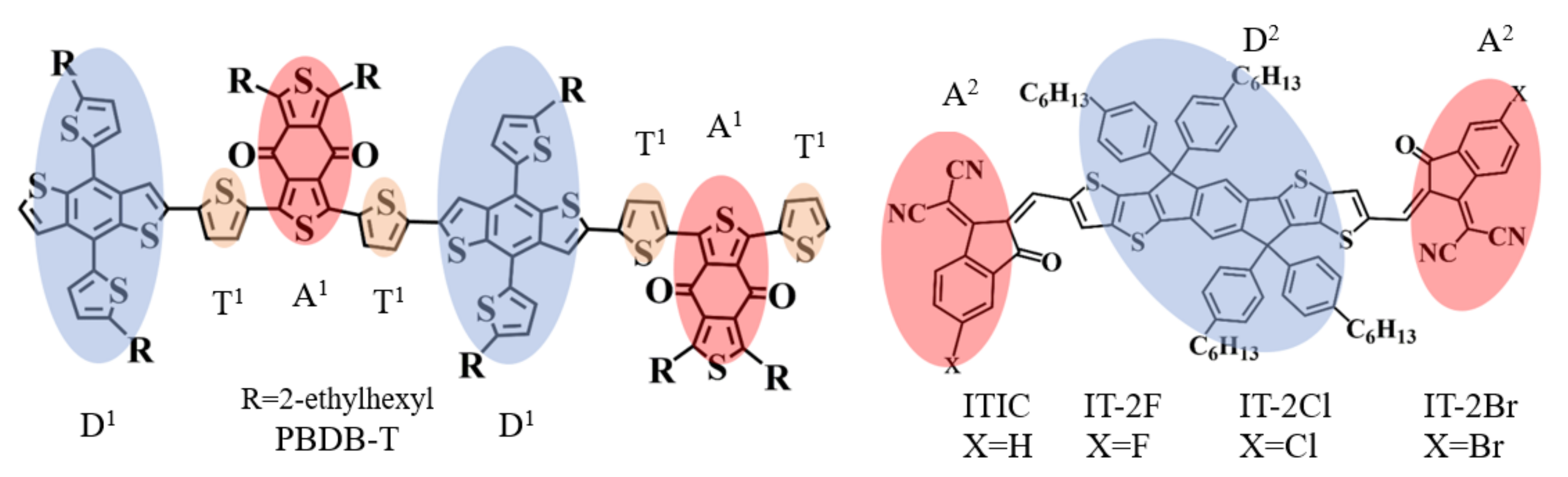
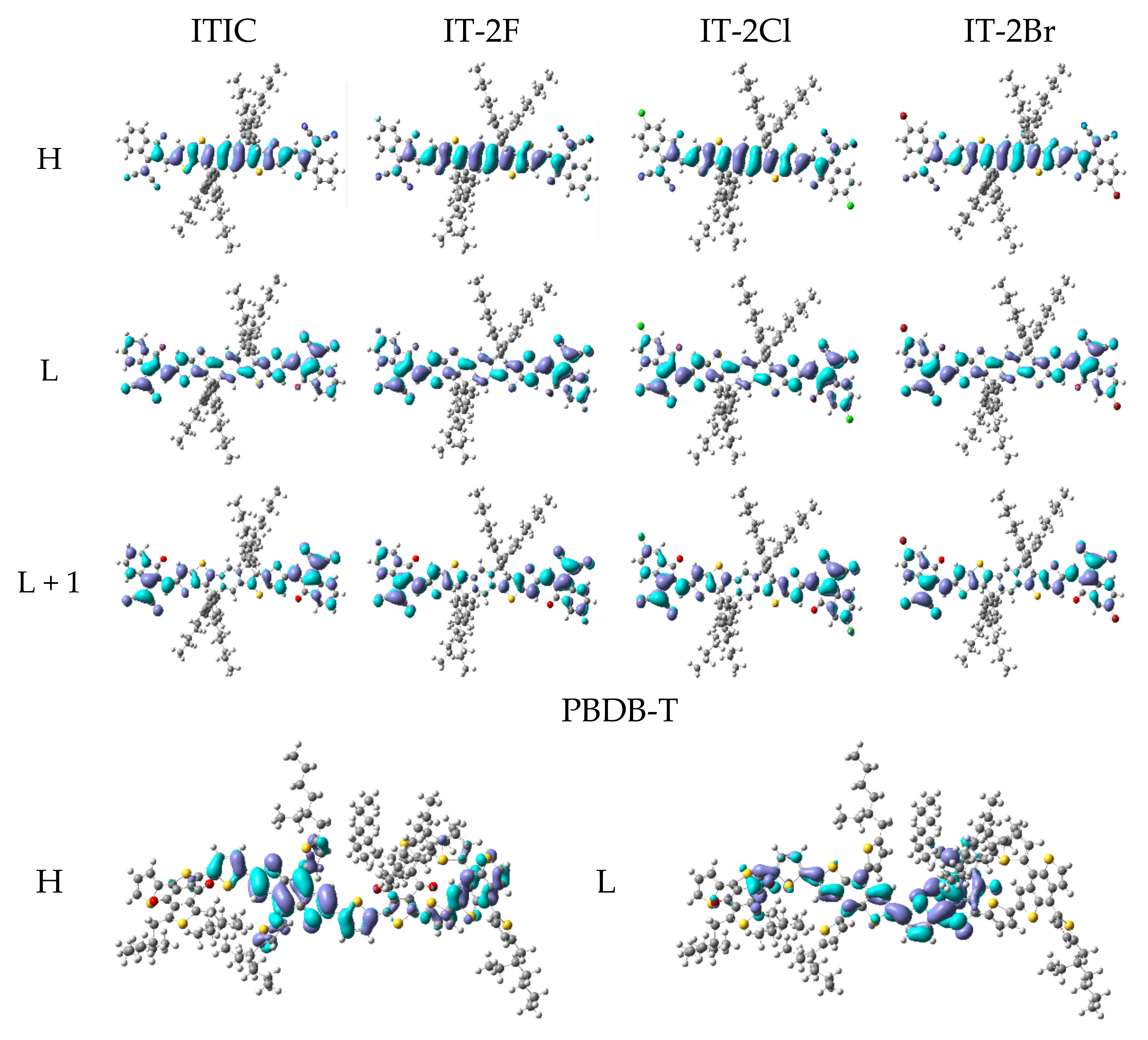
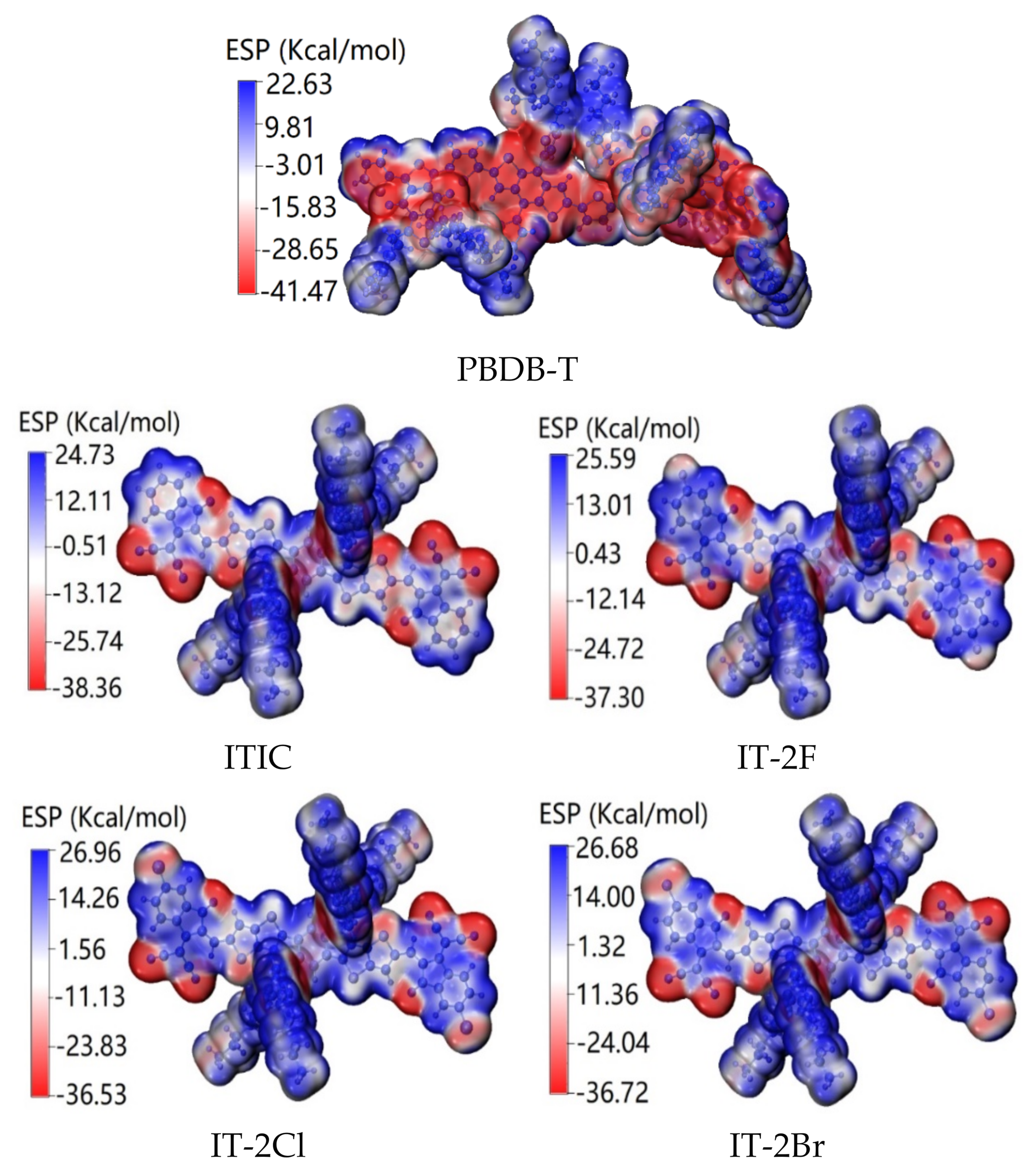
3.1. PBDB-T, ITIC and IT-2X (X = F, Cl, Br) Properties

The unit of PBDB-T with D-π-A type structure contains electron donor moiety based on benzo[1,2-b:4,5-b′]dithiophene (BDT) core, thienyl as π-spacer, and acceptor fragment based upon 5,7-bis(2-ethylhexyl)benzo[1,2-c:4,5-c′]dithiophene-4,8-dione (BDD) moiety, labeled as D1, T1, and A1 in Figure 1, respectively. For the A-D-A structure ITIC and IT-2X (X = F, Cl, Br), the acceptor fragments are 3,9-bis(2-methylene-(3-(1,1-dicyanomethylene)-indanone)) (DCI), and the 5,5,11,11-tetrakis(4hexylphenyl)-dithieno[2,3-d:2′,3′-d′]-s-indaceno[1,2-b:5,6-b′]-dithiophene (DID) fragment plays the role of donor. The optimized molecular structures of PBDB-T, ITIC and IT-2X (X = F, Cl, Br) are shown in Figure S1 in Supporting Material (SM), where the atomic serial numbers are also labeled. Table 1 lists the bond lengths, bond angles, and dihedral angles of the optimized PBDB-T, ITIC and IT-2X (X = F, Cl, Br) molecules, which can describe the distances and orientations among different moieties. More detailed geometric data are listed in Table S1 in SM. The dihedral angles between T1 and BDD/BDT moieties in PBDB-T indicate the non-planar main chain and significant torsion among these fragments, which result from the steric hindrance of alkyl in side chain and dione in BDD moiety. For ITIC and IT-2X (X = F, Cl, Br), the DCI and DID are planar fragments, cyano groups are coplanar with DCI, and small torsion angles between DCI and DID (3.8°, −7.6°, −7.8°, 3.2° in ITIC and IT-2X (X = F, Cl, Br), respectively) indicate their quasi-planar structures, meaning that introducing halogen atom into DCI fragments at end sites cannot significantly affect the planarity of backbone. The molecular backbone planarity can promote electron delocalization and enhance intramolecular CT. Moreover, the intramolecular hydrogen bonds between the O in DCI and the adjacent H in DID enhance the backbone planarity of ITIC and IT-2X (X = F, Cl, Br). The average C-X (X = H, F, Cl, Br) bond lengths are 1.09, 1.34, 1.74, and 1.89 Å, respectively. The increase of C-X bond lengths is caused by the size of the halogen atoms. Hence, considering the end sites halogenation and the variations of torsion angles between DCI and DID fragments, the halogenation of ITIC cannot significantly reduce backbone planarity and increase steric hindrance. However, due to the strong electronegativity of halogen atom, halogenation can induce stronger inter-molecular hydrogen bonds, which are favorable for molecular packing order, and then for efficient charge transport/transfer processes.
Table 2 shows the energies of HOMO, the lowest unoccupied molecular orbital (LUMO) and other MOs, as well as the HOMO-LUMO gap (H-Lgap) of PBDB-T, ITIC, and IT-2X (X = F, Cl, Br) molecules. The data indicate that the fluorination, chlorination, and bromination downshift the HOMO about 0.03, 0.04, and 0.05 eV, respectively, and reduce LUMO about 0.02, 0.08, and 0.08 eV, respectively, corresponding to slight variation of H-Lgap, agreeing experimental tendency of HOMO and LUMO variations by halogenation that were estimated by using electrochemical cyclic voltammetry measurements [40]. Also, halogenation of ITIC cannot effectively modify the energy differences between HOMO and HOMO-1, as well as between LUMO and LUMO+1, which were introduced as descriptors in machine-learning study of OPV materials [65]. Compared with ITIC, the downshift of HOMO and LUMO energies of IT-2X (X = F, Cl, Br) can be understood from the electronegativity of halogen atoms [66,67]. The strong electronegativity of halogen atoms causes more positive charges populated on the phenyl ring that bonded with halogen atoms, resulting in more electron localization and polarization effects [31]. Meanwhile, strong electronegativity of the halogen atom also changes the orbital hybridization of carbon atoms that bind with halogen atoms. The LUMO energy offset between donor and acceptor is usually considered as driving force for ED, while the energy offset between the LUMO of acceptor and the HOMO of donor is regarded as the driving force for CR. In terms of the data listed in Table 2, the halogenation of ITIC increase ED driving force and reduce CR driving force.
It was observed that the electron donor PBDB-T film exhibited good complementary absorption with those of acceptor ITIC and IT-2X (X = F, Cl, Br) [40]. PBDB-T has a good absorption characteristic in the region of 450–650 nm with absorption peaks at 615.5 nm and 567.5 nm, respectively. The absorption ranges of ITIC and IT-2X (X = F, Cl, Br) are between 600–815 nm. The complementary absorption of donor and acceptor in organic heterojunction are favorable to improve Jsc by enhancing photon harvest [68]. The simulated absorption spectrum presented in Figure 2 well reproduced experimental results, including absorption profile, the wavelength at absorption maxima (λmax) and relative shift among IT-2X (X = F, Cl, Br). For instance, the λmax of IT-2F is blue shifted 13.5 nm relative to those of IT-2Cl and IT-2Br, agreeing well with that of experimental 14 nm excellently [40].
Table 3 lists the main transition configurations, excited states characters (ESC), oscillator strengths (f), excitation energies and wavelengths of the selected excited states. More detailed data of PBDB-T, ITIC and IT-2X (X = F, Cl, Br) are given in Table S2 in SM. The related MOs are presented in Figure 3, and more MOs are shown in Figure S2 in SM. The HOMO of PBDB-T is mainly contributed by BDT and thienyl fragments, whereas the LUMO is mainly composed of BDD, thienyl and BDT fragments. Hence, in terms of transition configurations and MOs, the main character of PBDB-T’s S1 state is hybridized of CT and LE that is localized in donor fragment BDT (DLE). The PBDB-T’s other excited states that are listed in Table 3 are CT or hybridizations of CT and DLE. Considering the f of PBDB-T’s S1 state, the BDT and thienyl fragments are effective moieties in determining its light harvest efficiency. For ITIC and IT-2X (X = F, Cl, Br), their HOMOs are mainly contributed by DID fragment, while their LUMOs extend to DCI fragments. According to S1 transition configurations of ITIC and IT-2X (X = F, Cl, Br), the overlap between HOMO and LUMO means the LE of DID, which belongs to DLE. However, the relocation between HOMO and LUMO suggests CT excitations. Hence, the S1 states of ITIC and IT-2X (X = F, Cl, Br) hybridize the CT and DLE. The other excited states listed in Table 3 are also hybrid excitations. Since LE usually corresponds to large f that determine light harvest efficiency, DID is an effective chromophore for light harvest of ITIC and IT-2X (X = F, Cl, Br). CT excitations are also expected for increasing current density, efficient ED, and charge transfer/transport. The hybrid excitations combine the merits of CT and LE. Furthermore, halogenation doesn’t significantly influence on excitation properties (transition configurations and ESC, etc.) of IT-2X (X = F, Cl, Br) except the slight change of excitation energies. The S1 excitation energies indicate that fluorination slightly increases excitation energy, while the chlorination and bromination slight reduce excitation energies. This can be understood from the transition configurations and halogenation effects on frontier MO energies. Moreover, there are some quasi-degenerated excited states (see Table S2 in SM), for instance, S11 and S12, S13, and S14 of IT-2X (X = F, Cl, Br). The CT of these excited states can be enhanced due to coherence among quasi-degenerated states.
The CDD, CT distances Δd and the transferred charges Δq for the selected low-lying excited states of ITIC and IT-2X (X = F, Cl, Br) are shown in Figure S3 in SM. The interpenetrating of electron density increment/decrement regions and small Δq support these excited states are hybrid excitations of CT and LE. Moreover, the CDD of ITIC and IT-2X (X = F, Cl, Br) suggest that the DCI and DID fragments are electron acceptor and donors, respectively, and the phenyl moieties in side chains also play the role of electron donor. In addition, the A-D-A type structure and symmetry of ITIC and IT-2X (X = F, Cl, Br) result into small Δd of the excited states presented in Figure S3.
Figure 4 shows the ESP of ITIC, IT-2X (X = F, Cl, Br), and PBDB-T molecules. For PBDB-T, the low ESP is mainly contributed by backbone, and the high ESP is dominated by side chains. For ITIC and IT-2X (X = F, Cl, Br), the high ESP are mainly contributed by alkyl in side-chains, and the low ESP mainly concentrate on O, S, and N atoms in backbone. Moreover, halogenation reduces the ESP at substitution sites. The average ESP values are −48.6, 63.8, 85.3, 105.9 and 106.4 Kcal/mol for PBDB-T, ITIC, IT-2F, IT-2Cl, and IT-2Br, respectively. Since the increased average ESP value of electron acceptor can increase the electron accepting ability [69], the halogenation of ITIC promotes their electron accepting ability, which is favorable for enhancing CT between donor-acceptor complexes [32]. Furthermore, halogenation of ITIC also generate the enlarged ESP differences between donor and acceptors, and further induce stronger interface electric field that can promote the ED and CT at the donor-acceptor interface [33]. Moreover, the enlarged ESP difference between donor and acceptors may also suppressing non-radiation recombination (which was regarded as one of the important energetic losses route in OPV) [70].

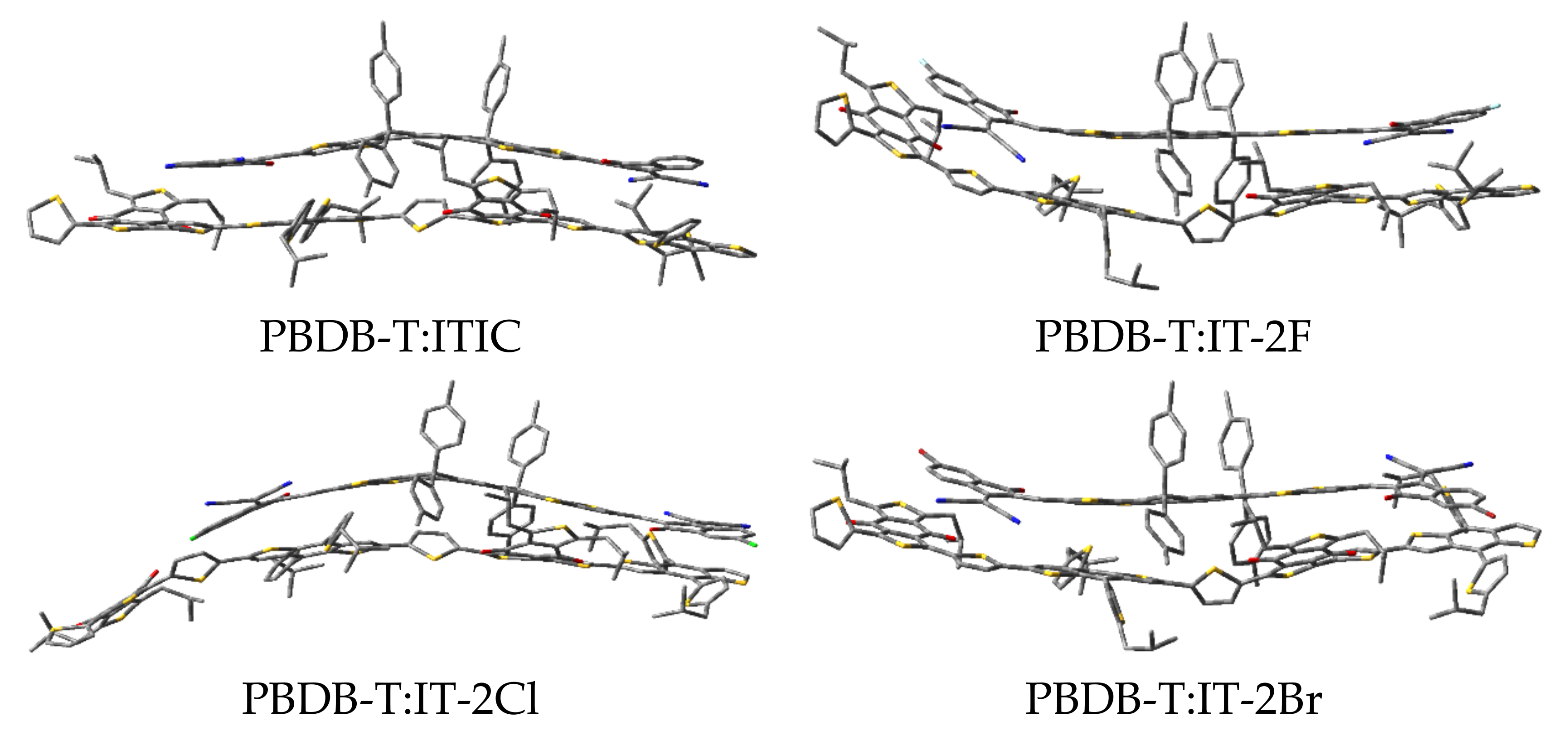
3.2. PBDB-T:ITIC and PBDB-T:IT-2X (X = F, Cl, Br) Properties

The optimized structures of PBDB-T:ITIC and PBDB-T:IT-2X (X = F, Cl, Br) complexes are shown in Figure 5, and the selected geometric parameters are given in Table 4. Compared with those of the corresponding geometric parameters of the ITIC and IT-2X (X = F, Cl, Br) molecules, the changes in bond lengths and angles are smaller than 0.001 Å and 1° for the corresponding electron acceptors in complexes, respectively. The data in Table 4 indicate that the non-bond intermolecular interaction reduce the backbone planarity of ITIC and IT-2X (X = F, Cl, Br) in complexes. The distance between the mass centers of donor and acceptor in PBDB-T:ITIC and PBDB-T:IT-2X (X = F, Cl, Br) complexes are 4.32, 3.03, 5.86, and 3.19 Å, respectively. The maximum dihedral angle variations in complexes locate at the torsion between the donor DID and acceptor DCI fragments in ITIC and IT-2X (X = F, Cl, Br), and the corresponding values are 11°, 19°, 9°, 13°, respectively. Similarly, relative to those of isolated PBDB-T molecules, the changes of bond lengths and angles in complexes are very tiny. Due to the absence of intramolecular hydrogen bonds in PBDB-T, the PBDB-T’s backbone is more flexible than ITIC and IT-2X (X = F, Cl, Br), corresponding to several remarkable dihedral angle changes of PBDB-T in complexes. The intermolecular non-bonding interactions can be evaluated from the binding energies (Eb) of the complexes. The calculated results show that halogenation increases Eb (see Table 5), indicating that halogenation enhances the non-bonding intermolecular interaction between electron donor and acceptor, which is beneficial to improve the morphology regioregularity that was approved by relatively smooth surfaces of PBDB-T:IT-2X (X = F, Br) blended films [40]. The data of quadrupole moments of ITIC and halogenated systems (see Table S5 in SM) indicate halogenation results into an increase of the quadrupole, and then contribute to enhance quadrupole interaction between the donor and acceptor molecules in complexes [71]. Moreover, the large Eb may enhance interface stability and improve resistance to thermal/light stress [72].
Table 5 also gives the HOMO and LUMO energies, as well as the H-Lgap values of the PBDB-T:ITIC and PBDB-T:IT-2X (X = F, Cl, Br) complexes. Similar to that of ITIC and IT-2X (X = F, Cl, Br) molecules, the fluorination slightly elevates the LUMO of complex with broadening H-Lgap, whereas the chlorination and bromination induce down-shift of LUMO of complexes, corresponding to H-Lgap reductions. Among these complexes, the H-Lgap of PBDB-T:IT-2Cl complex is the smallest. According to Shockley-Queisser theory, the lowering H-Lgap tends to reduce energy loss [73]. Hence, chlorination and bromination may be helpful to suppress energy loss.
The absorption spectra of complexes that were presented in Figure 2b indicate that the halogenation not only induce the red-shift about 30–65 nm, but also enhance absorption in longer wavelength regions. The enhanced optical absorption is expected for prominent OPV materials since it can improve the utilization of photon energy from solar radiation.
Organic materials with a smaller exciton binding energy (Eexb) usually show better charge separation efficiency, which impacts the free charge carrier generation in photon-to-electricity conversion of OPV. The calculated Eexb of PBDB-T:ITIC and PBDB-T:IT-2X (X = F, Cl, Br) complexes are 0.63, 0.59, 0.62, and 0.60 eV, respectively, meaning that halogenation reduces Eexb. The small Eexb is favorable to reduce interfacial energy offsets toward efficient ED for free charge carrier generation in OPV [74,75,76]. In terms of the related parameters for calculating Eexb listed in Table S6, the main reason for Eexb reduction is halogenation increases electron affinity.
Table 6 lists the excitation energies, corresponding oscillator strengths, excitation wavelengths, excited state characteristics and the main transition configurations of PBDB-T:ITIC and PBDB-T:IT-2X (X = F, Cl, Br) complexes. Details of more excited states are listed in Table S4 in SM. Figure 6 presents the selected MOs of PBDB-T:ITIC and PBDB-T:IT-2X (X = F, Cl, Br) complexes. More MOs are showing in Figure S4 in SM. According to transition configurations and MOs, the excited states’ characters were assigned. The S1 states of all the complexes in this work are CT excitations, and the energies of local excitation in acceptor (ALE) and in donor (DLE) are higher than that of CT states, indicating energetic permission for ED. Comparing the CT state energy of PBDB-T:ITIC complex, the fluorination and bromination increase CT energy 0.11 and 0.02 eV, respectively, while the chlorination reduces CT energy 0.13 eV. Combined with the empirical formula of VOC [77], the large CT excitation energy is beneficial to improve the VOC. Meanwhile, the halogenation effects on CT excitation energies of these complexes are similar to that on H-Lgap, which can be understood from transition configurations and weak intermolecular interaction between PBDB-T and acceptor in complexes. In addition, couple of excited states with higher energy of these complexes exhibit hybridization of CT and local excitation (see Table S4 in SM), which are favorable to charge carrier generation by hot ED processes [78].
The Δq and Δd of the PBDB-T:ITIC and PBDB-T:IT-2X (X = F, Cl, Br) complexes are also calculated to quantitatively describe the CT and LE of the complexes. The CDD, Δq and Δd of the selected excited states are given in Figure 7 (more details to see Figure S5 in SM). Apparently, the Δq labeled in Figure 7 and Figure S4 support the assignments of excited state characters. The halogenation of the complexes increases Δq of CT excitations. The Δd for most of excited CT states are in range of typical intermolecular distances between donor and acceptor in organic photovoltaic heterojunctions. Furthermore, the order of Δq related to S1 states of the halogenated complexes is same as that of experimental JSC [40]. The Δq was demonstrated as one of the critical factors to determine JSC [79].

3.3. Rate Constants of Charge Transfer, Exciton Dissociation and Charge Recombination

Table 7 lists the calculated λ (including λi and λext), ∆G and V of the CT, CR and ED processes, which are required for calculating rate constants. Tables S6–S7 in SM provide the detailed parameters for calculating V. Since the halogenation site is at the end group of ITIC, the halogenation influences on λ are very tiny for each process (<0.01 eV). Meanwhile, the halogenation effects on ∆G are smaller than 0.1 eV for each process. As to V, apart from chlorination of ED process, the halogenation reduce V for each process. Compared with the rates of PBDB-T:ITIC complex, the fluorination increase CT rate and decrease CR rate. However, both the chlorination and bromination reduce CT rates and increase ED rates. For ED processes, the fluorination and chlorination decrease ED rates, while the bromination increases ED rate. In real OPV devices, CT, CR, and ED processes are competitive, resulting into ultimate performance. Considering the CT and ED rates are more than 13 orders larger than CR rates, meaning the efficient ED in these OPV devices. In the experiment, the ratio of the photocurrent density (Jph) and its saturation (Jsat) is used to evaluate exciton dissociation efficiency and charge collection [40]. Charge collection is mainly determined by cathode/anode layers and their interfaces. Due to the same OPV architecture and experimental condition, the Jsat must be same. Hence, the Jph/Jsat ratios expose the ED efficiency. The Jph/Jsat ratios of PBDB-T:ITIC, PBDB-T:IT-2F, PBDB-T:IT-2Cl and PBDB-T:IT-2Br were 93.3%, 92.2%, 90.6%, and 94.8%, respectively [40], agreeing well with the tendency of the calculated ED rates.

4. Conclusions

In this work, based on the quantum chemical calculations and the selected model systems which include donor PBDB-T, acceptors ITIC and IT-2X (X = F, Cl, Br), the halogenation mechanism and its effects on photovoltaic performances were studied. The main conclusions are as followings:
Halogenation of electron acceptor ITIC in OPV heterojunction slightly affect the molecular geometric structures, MO energy levels, optical absorption spectra, exciton binding energies, and excitation properties. However, the halogenation of ITIC significantly enlarge the ESP difference between electron acceptor and donor PBDB-T with the order from fluorination and chlorination to bromination that can induce an electric field at the heterojunction interface, and the halogenation can also increase the transferred charges of CT states for the complexes, corresponding to the increase of Jsc. Meanwhile, the halogenation effects on CT energies and electron processes rates depend on different elements. No matter which kinds of elements were introduced in the halogenation of the acceptor, the ED is always efficient in these OPV devices since the ED rates are more than 13-fold larger than CR rates. Hence, the main halogenation effects on OPV performances can be ascribed to its influences on ESP, transferred charges, and electron processes rates.
This work provides help in understanding the mechanism of halogenation influences on OPV performances of acceptor material properties, and is also conducive to the design of new high-performance acceptor materials with the aid of halogenation strategy.

Supplementary Materials

The following are available online at https://www.mdpi.com/article/10.3390/nano11123417/s1. Figure S1: The optimized structures of PBDB-T, ITIC and IT-2X (X = F, Cl, Br) in gas phase. The atomic serial numbers are also labeled to give geometrical parameters. The hydrogen atoms are omitted for clarity. (ωB97XD/6-31G**). Figure S2: The selected frontier molecular orbitals involved in transition configurations for the ITIC and IT-2X (X = F, Cl, Br) and PBDB-T. (LC-PBE/6-31G**; ω = 0.155, 0.167, 0.144, 0.155, 0.155 Bohr−1; α = 0.200, β = 0.086; εs = 3.5, εd = 3.3; H = HOMO, L = LUMO). Figure S3: Charge density difference for the low-lying excited states of ITIC, IT-2X (X = F, Cl, Br) and PBDB-T molecules. The regions colored in red (blue) indicate the increase (decrease) of electron density during excitation processes, respectively. The charge transfer distance Δd and the transferred charges Δq are shown. (LC-PBE/6-31G**; ω = 0.155, 0.167, 0.144, 0.155 Bohr−1; α = 0.200, β = 0.086; εs = 3.5, εd = 3.3). Figure S4: Selected frontier molecular orbitals for PBDB-T:ITIC and PBDB-T:IT-2X (X = F, Cl, Br) complexes. (LC-PBE/6-31G**; ω = 0.155, 0.167, 0.144, 0.155 Bohr−1; α = 0.200, β = 0.086; εs = 3.5, εd = 3.3; H = HOMO, L = LUMO). Figure S5: Charge density difference for the low-lying excited states of PBDB-T:ITIC and PBDB-T:IT-2X (X = F, Cl, Br) complexes. The regions colored in red (blue) indicate the increase (decrease) of electron density during excitation processes, respectively. The charge transfer distance Δd and the transferred charges Δq are shown. (LC-PBE/6-31G**; ω = 0.155, 0.167, 0.144, 0.155 Bohr−1; α = 0.200, β = 0.086; εs = 3.5, εd = 3.3), Table S1: The selected geometrical parameters, including bond lengths (in Å), bond angles (in°) and dihedral angles (in°) which were defined by two, three and four atoms, respectively. (ωB97XD/6-31G**). Table S2: Electronic transition energies (in eV), excitation wavelengths (in nm), excited states characters (ESC), corresponding oscillator strengths (f), and the main transition configurations with coefficients larger than 10% for the PBDB-T, ITIC and IT-2X (X = F, Cl, Br). CT (ACT) represents the charge transfer from the donor (acceptor) segment to the acceptor (donor) segment. DLE (ALE) represents the local excitation that occurs on the donor (acceptor) segment. (LC-PBE/6-31G**; α = 0.200, β = 0.086; εs = 3.5, εd = 3.3; ω unit is Bohr−1). Table S3: The selected bond lengths (in Å) and bond angles (in °) of PBDB-T:ITIC and PBDB-T:IT-2X (X = F, Cl, Br) complexes. The atomic serial numbers is shown in Figure S1 of supporting material. (ωB97XD/6-31G**). Table S4: Electronic transition energies (in eV), corresponding oscillator strengths (f), excitation wavelengths (in nm), excited states characters (ESC) and main transition configurations with coefficients larger than 10% for PBDB-T:ITIC and PBDB-T:IT-2X (X = F, Cl, Br) complexes. (LC-PBE/6-31G**; εs = 3.5, εd = 3.3; α = 0.200, β = 0.086; the ω unit is Bohr−1). Table S5: The components of the dipole moment (in Debye) and quadrupole moment (in Debye-Ang) of ITIC and IT-2X (X = F, Cl, Br) molecules. ( U 1 = X 2 + Y 2 + Z 2 ; LC-PBE/6-31G**; ω = 0.155, 0.167, 0.144, 0.155 Bohr−1; α = 0.200, β = 0.086; εs = 3.5, εd = 3.3). Table S6: Calculated electronic coupling V (in eV) in CR process of PBDB-T:ITIC and PBDB-T:IT-2X (X = F, Cl, Br) complexes. u correspond the transition dipole moment (in a.u); μg and μe represent the dipole moment at the ground state and excited state (in Debye), respectively. Δμge indicates the change in dipole moment between the ground state and the lowest singlet excited state (in Debye); ΔE is the energy differnence between the ground state and the excited state (in eV). (LC-PBE/6-31G**; ω = 0.155, 0.167, 0.144, 0.155 Bohr−1; α = 0.200, β = 0.086; εs = 3.5, εd = 3.3). Table S7: Electronic coupling V (in meV) in CT and ED process of PBDB-T:ITIC and PBDB-T:IT-2X (X = F, Cl, Br) complexes. Ei and Ef are the energy (in eV) of initial and final states; Sif covresponds the overlap matrix element, and Hif (meV) is the off-diagonal hamiltonian of charge-localized state. (LC-PBE/6-31G**; ω = 0.155, 0.167, 0.144, 0.155 Bohr−1; α = 0.200, β = 0.086; εs = 3.5, εd = 3.3).

Author Contributions

Conceptualization, C.Z.; Methodology, C.Z.; Data curation, Y.W. (Yu Wang); Visualization, Y.W. (Yu Wang); Validation, C.Z., B.Y., L.Y. and J.G.; Writing—original draft, Y.W. (Yu Wang); Writing—review& editing, C.Z.; Formal analysis, C.Z., B.Y., L.Y., J.G., Z.L., Y.W. (Youzhi Wu) and H.C., Investigation, Y.W. (Yu Wang) and C.Z.; Resources, C.Z.; Supervision, C.Z.; Project administration, C.Z.; Funding acquisition, C.Z. All authors have read and agreed to the published version of the manuscript.

Funding

This research was funded by the National Natural Science Foundation of China (Grant No.11964016) and the HongLiu First-class Disciplines Development Program of Lanzhou University of Technology.

Institutional Review Board Statement

Not applicable.

Informed Consent Statement

Not applicable.

Data Availability Statement

The data presented in this study are available on request from the corresponding author.

Acknowledgments

This work was supported by the National Natural Science Foundation of China (Grant No.11964016) and the HongLiu First-class Disciplines Development Program of Lanzhou University of Technology. The authors were grateful to the National Supercomputing Center in Shenzhen.

Conflicts of Interest

The authors declare no conflict of interest.

References

  1. Cheng, P.; Li, G.; Zhan, X.; Yang, Y. Next-generation organic photovoltaics based on non-fullerene acceptors. Nat. Photonics 2018, 12, 131–142. [Google Scholar] [CrossRef]
  2. Inganas, O. Organic photovoltaics over three decades. Adv. Mater. 2018, 30, 1800388–1800413. [Google Scholar] [CrossRef] [PubMed]
  3. Lu, L.; Zheng, T.; Wu, Q.; Schneider, A.M.; Zhao, D.; Yu, L. Recent advances in bulk heterojunction polymer solar cells. Chem. Rev. 2015, 115, 12666–12731. [Google Scholar] [CrossRef]
  4. Liu, Q.; Jiang, Y.; Jin, K.; Qin, J.; Xu, J.; Li, W.; Xiong, J.; Liu, J.; Xiao, Z.; Sun, K.; et al. 18% efficiency organic solar cells. Sci. Bull. 2020, 65, 272–275. [Google Scholar] [CrossRef] [Green Version]
  5. Lin, Y.; Nugraha, M.I.; Firdaus, Y.; Scaccabarozzi, A.D.; Aniés, F.; Emwas, A.H.; Yengel, E.; Zheng, X.; Liu, J.; Wahyudi, W.; et al. A simple n-dopant derived from diquat boosts the efficiency of organic solar cells to 18.3%. ACS Energy Lett. 2020, 5, 3663–3671. [Google Scholar] [CrossRef]
  6. Lin, Y.; Firdaus, Y.; Isikgor, F.H.; Nugraha, M.I.; Yengel, E.; Harrison, G.T.; Hallani, R.; El-Labban, A.; Faber, H.; Ma, C.; et al. Self-assembled monolayer enables hole transport layer-free organic solar cells with 18% efficiency and improved operational stability. ACS Energy Lett. 2020, 5, 2935–2944. [Google Scholar] [CrossRef]
  7. Cui, Y.; Xu, Y.; Yao, H.; Bi, P.; Hong, L.; Zhang, J.; Zu, Y.; Zhang, T.; Qin, J.; Ren, J.; et al. Single-junction organic photovoltaic cell with 19% efficiency. Adv. Mater. 2021, 41, 2102420. [Google Scholar] [CrossRef]
  8. Nam, M.; Cha, M.; Lee, H.H.; Hur, K.; Lee, K.T.; Yoo, J.; Han, I.K.; Kwon, S.J.; Ko, D.H. Long-term efficient organic photovoltaics based on quaternary bulk heterojunctions. Nat. Commun. 2017, 8, 14068–14077. [Google Scholar] [CrossRef] [Green Version]
  9. Lu, L.; Kelly, M.A.; You, W.; Yu, L. Status and prospects for ternary organic photovoltaics. Nat. Photonics 2015, 9, 491–500. [Google Scholar] [CrossRef]
  10. Wang, Y.; Zhang, Y.; Qiu, N.; Feng, H.; Gao, H.; Kan, B.; Ma, Y.; Li, C.; Wan, X.; Chen, Y. A halogenation strategy for over 12% efficiency nonfullerene organic solar cells. Adv. Energy Mater. 2018, 8, 1702870–1702876. [Google Scholar] [CrossRef]
  11. Zhang, M.; Zeng, M.; Ye, L.; Tan, S.; Zhao, B.; Ryu, H.S.; Woo, H.Y.; Sun, Y. Effects of monohalogenated terminal units of non-fullerene acceptors on molecular aggregation and photovoltaic performance. Sol. Energy 2020, 208, 866–872. [Google Scholar] [CrossRef]
  12. Furukawa, S.; Yasuda, T. Strategic end-halogenation of π-conjugated small molecules enabling fine morphological control and enhanced performance of organic solar cells. J. Mater. Chem. A 2019, 7, 14806–14815. [Google Scholar] [CrossRef]
  13. Yao, H.; Wang, J.; Xu, Y.; Zhang, S.; Hou, J.H. Recent progress in chlorinated organic photovoltaic materials. Acc. Chem. Res. 2020, 53, 822–832. [Google Scholar] [CrossRef]
  14. Chen, Y.; Ma, R.; Liu, T.; Xiao, Y.; Kim, H.K.; Zhang, J.; Ma, C.; Sun, H.; Bai, F.; Guo, X.; et al. Side-chain engineering on Y-series acceptors with chlorinated end groups enables high-performance organic solar cells. Adv. Energy Mater. 2021, 20, 2003777. [Google Scholar] [CrossRef]
  15. Zhao, Q.; Qu, J.; He, F. Chlorination: An effective strategy for high-performance organic solar cells. Adv. Sci. 2020, 7, 2000509. [Google Scholar] [CrossRef]
  16. Zheng, Y.Q.; Wang, Z.; Dou, J.H.; Zhang, S.D.; Luo, X.Y.; Yao, Z.F.; Wang, J.Y.; Pei, J. Effect of halogenation in isoindigo-based polymers on the phase separation and molecular orientation of bulk heterojunction solar cells. Macromolecules 2015, 48, 5570–5577. [Google Scholar] [CrossRef]
  17. Li, Y.; Lin, J.D.; Che, X.; Qu, Y.; Liu, F.; Liao, L.S.; Forrest, S.R. High efficiency near-infrared and semitransparent non-fullerene acceptor organic photovoltaic cells. J. Am. Chem. Soc. 2017, 139, 17114–17119. [Google Scholar] [CrossRef]
  18. Zhang, J.; Li, Y.; Hu, H.; Zhang, G.; Ade, H.; Yan, H. Chlorinated thiophene end groups for highly crystalline alkylated non-fullerene acceptors toward efficient organic solar cells. Chem. Mater. 2019, 31, 6672–6676. [Google Scholar] [CrossRef]
  19. Cui, Y.; Yao, H.; Zhang, J.; Zhang, T.; Wang, Y.; Hong, L.; Xian, K.; Xu, B.; Zhang, S.; Peng, J.; et al. Over 16% efficiency organic photovoltaic cells enabled by a chlorinated acceptor with increased open-circuit voltages. Nat. Commun. 2019, 10, 2515–2522. [Google Scholar] [CrossRef]
  20. Ma, S.; Wu, S.; Zhang, J.; Song, Y.; Tang, H.; Zhang, K.; Huang, F.; Cao, Y. Heptacyclic S, N-heteroacene-based near-infrared nonfullerene acceptor enables high-performance organic solar cells with small highest occupied molecular orbital offsets. ACS Appl. Mater. Inter. 2020, 12, 51776–51784. [Google Scholar] [CrossRef]
  21. Wang, Q.; Li, M.; Zhang, X.; Qin, Y.; Wang, J.; Zhang, J.; Hou, J.H.; Janssen, R.A.J.; Geng, Y. Carboxylate-substituted polythiophenes for efficient fullerene-free polymer solar cells: The effect of chlorination on their properties. Macromolecules 2019, 52, 4464–4474. [Google Scholar] [CrossRef]
  22. Zhang, Q.; Yan, L.; Jiao, X.; Peng, Z.; Liu, S.; Rech, J.J.; Klump, E.; Ade, H.; So, F.; You, W. Fluorinated thiophene units improve photovoltaic device performance of donor–acceptor copolymers. Chem. Mater. 2017, 29, 5990–6002. [Google Scholar] [CrossRef]
  23. Duan, C.; Zango, G.; Garcia Iglesias, M.; Colberts, F.J.; Wienk, M.M.; Martinez-Diaz, M.V.; Janssen, R.A.; Torres, T. The role of the axial substituent in subphthalocyanine acceptors for bulk-heterojunction solar cells. Angew. Chem. Int. Ed. Engl. 2017, 56, 148–152. [Google Scholar] [CrossRef]
  24. Chao, P.; Chen, H.; Pu, M.; Zhu, Y.; Han, L.; Zheng, N.; Zhou, J.; Chang, X.; Mo, D.; Xie, Z.; et al. Chlorinated benzo[1;2-b:4;5-c′]dithiophene-4;8-dione polymer donor: A small atom makes a big difference. Adv. Sci. 2021, 8, 2003641. [Google Scholar] [CrossRef]
  25. Ji, H.; Li, J.; Du, M.; Yang, J.; Tang, A.; Li, G.; Guo, Q.; Zhou, E. Fluorination of the quinoxaline-based p-type polymer and n-type small molecule for high VOC organic solar cells. J. Phys. Chem. C 2021, 125, 10876–10882. [Google Scholar] [CrossRef]
  26. Yu, H.; Qi, Z.; Yu, J.; Xiao, Y.; Sun, R.; Luo, Z.; Cheung, A.M.H.; Zhang, J.; Sun, H.; Zhou, W.; et al. Fluorinated end group enables high-performance all-polymer solar cells with near-infrared absorption and enhanced device efficiency over 14%. Adv. Energy Mater. 2020, 11, 2003171. [Google Scholar] [CrossRef]
  27. Ma, R.; Li, G.; Li, D.; Liu, T.; Luo, Z.; Zhang, G.; Zhang, M.; Wang, Z.; Luo, S.; Yang, T.; et al. Understanding the effect of end group halogenation in tuning miscibility and morphology of high-performance small molecular acceptors. Sol. RRL 2020, 4, 2000250. [Google Scholar] [CrossRef]
  28. Qiu, W.; Zheng, S. Designing and screening high-performance non-fullerene acceptors: A theoretical exploration of modified Y6. Sol. RRL 2021, 5, 2100023. [Google Scholar] [CrossRef]
  29. Qiu, W.; Zheng, S. Effects of functionalization of Y6 end-groups with electron-withdrawing groups on the photovoltaic properties at the donor-acceptor interfaces of PM6/Y6 OSCs: A theoretical insight. Org. Electron. 2021, 96, 106235. [Google Scholar] [CrossRef]
  30. Ashokan, A.; Wang, T.; Ravva, M.K.; Brédas, J.-L. Impact of solution temperature-dependent aggregation on the solid-state packing and electronic properties of polymers for organic photovoltaics. J. Mater. Chem. C 2018, 6, 13162–13170. [Google Scholar] [CrossRef]
  31. Benatto, L.; Koehler, M. Effects of fluorination on exciton binding energy and charge transport of π-conjugated donor polymers and the ITIC molecular acceptor: A theoretical study. J. Phys. Chem. C 2019, 123, 6395–6406. [Google Scholar] [CrossRef]
  32. Liao, Q.; Kang, Q.; Yang, Y.; An, C.; Xu, B.; Hou, J.H. Tailoring and modifying an organic electron acceptor toward the cathode interlayer for highly efficient organic solar cells. Adv. Mater. 2020, 32, 1906557–1906565. [Google Scholar] [CrossRef]
  33. Bai, R.R.; Zhang, C.R.; Liu, Z.J.; Chen, X.K.; Wu, Y.Z.; Wang, W.; Chen, H.S. Electric field effects on organic photovoltaic heterojunction interfaces: The model case of pentacene/C60. Comput. Theor. Chem. 2020, 1186, 112914. [Google Scholar] [CrossRef]
  34. Mahmood, A.; Irfan, A. Effect of fluorination on exciton binding energy and electronic coupling in small molecule acceptors for organic solar cells. Comput. Theor. Chem. 2020, 1179, 112797. [Google Scholar] [CrossRef]
  35. Bai, R.R.; Zhang, C.R.; Wu, Y.Z.; Shen, Y.L.; Liu, Z.J.; Chen, H.S. Donor halogenation effects on electronic structures and electron process rates of donor/C60 heterojunction interface: A theoretical study on FnZnPc (n = 0, 4, 8, 16) and ClnSubPc (n = 0, 6). J. Phys. Chem. A 2019, 123, 4034–4047. [Google Scholar] [CrossRef]
  36. Doumon, N.Y.; Dryzhov, M.V.; Houard, F.V.; Le Corre, V.M.; Rahimi Chatri, A.; Christodoulis, P.; Koster, L.J.A. Photostability of fullerene and non-fullerene polymer solar cells: The role of the acceptor. ACS. Appl. Mater. Inter. 2019, 11, 8310–8318. [Google Scholar] [CrossRef] [Green Version]
  37. Yang, Y. The original design principles of the Y-series nonfullerene acceptors, from Y1 to Y6. ACS Nano 2021. [Google Scholar] [CrossRef]
  38. Zhang, Y.; Yao, H.; Zhang, S.; Qin, Y.; Zhang, J.; Yang, L.; Li, W.; Wei, Z.; Gao, F.; Hou, J. Fluorination vs. chlorination: A case study on high performance organic photovoltaic materials. Sci. China Chem. 2018, 61, 1328–1337. [Google Scholar] [CrossRef]
  39. Zhang, H.; Yao, H.; Hou, J.X.; Zhu, J.; Zhang, J.; Li, W.; Yu, R.; Gao, B.; Zhang, S.; Hou, J.H. Over 14% efficiency in organic solar cells enabled by chlorinated nonfullerene small-molecule acceptors. Adv. Mater. 2018, 30, 1800613–1800619. [Google Scholar] [CrossRef]
  40. Lu, S.; Li, F.; Zhang, K.; Zhu, J.; Cui, W.; Yang, R.; Yu, L.; Sun, M. Halogenation on terminal groups of ITIC based electron acceptors as an effective strategy for efficient polymer solar cells. Sol. Energy 2020, 195, 429–435. [Google Scholar] [CrossRef]
  41. Price, S.C.; Stuart, A.C.; Yang, L.; Zhou, H.; You, W. Fluorine substituted conjugated polymer of medium band gap yields 7% efficiency in polymer-fullerene solar cells. J. Am. Chem. Soc. 2011, 133, 4625–4631. [Google Scholar] [CrossRef]
  42. Chen, T.W.; Peng, K.L.; Lin, Y.W.; Su, Y.J.; Ma, K.J.; Hong, L.; Chang, C.C.; Hou, J.H.; Hsu, C.S. A chlorinated nonacyclic carbazole-based acceptor affords over 15% efficiency in organic solar cells. J. Mater. Chem. A 2020, 8, 1131–1137. [Google Scholar] [CrossRef]
  43. Luo, Z.H.; Sun, R.; Zhong, C.; Liu, T.; Zhang, G.Y.; Zou, Y.; Jiao, X.C.; Min, J.; Yang, C.L. Altering alkyl-chains branching positions for boosting the performance of small-molecule acceptors for highly efficient nonfullerene organic solar cells. Sci. China Chem. 2020, 63, 361–369. [Google Scholar] [CrossRef]
  44. Yu, H.; Pan, M.; Sun, R.; Agunawela, I.; Zhang, J.; Li, Y.; Qi, Z.; Han, H.; Zou, X.; Zhou, W.; et al. Regio-regular polymer acceptors enabled by determined fluorination on end groups for all-polymer solar cells with 15.2% efficiency. Angew. Chem. Int. Ed. Engl. 2021, 60, 10137–10146. [Google Scholar] [CrossRef]
  45. Chai, J.D.; Head-Gordon, M. Long-range corrected hybrid density functionals with damped atom-atom dispersion corrections. Phys. Chem. Chem. Phys. 2008, 10, 6615–6620. [Google Scholar] [CrossRef] [Green Version]
  46. Petersson, G.A.; Bennett, A.; Tensfeldt, T.G.; Al-Laham, M.A.; Shirley, W.A.; Mantzaris, J.A. A complete basis set model chemistry. Part 1. The total energies of closed-shell atoms and hydrides of the first-row elements. J. Chem. Phys 1988, 89, 2193–2218. [Google Scholar] [CrossRef]
  47. Cao, Z.; Yang, S.; Wang, B.; Shen, X.; Han, G.; Yi, Y. Multi-channel exciton dissociation in D18/Y6 complexes for high-efficiency organic photovoltaics. J. Mater. Chem. A 2020, 8, 20408–20413. [Google Scholar] [CrossRef]
  48. Zheng, Y.; Huang, J.; Wang, G.; Kong, J.; Huang, D.; Mohadjer Beromi, M.; Hazari, N.; Taylor, A.D.; Yu, J. A highly efficient polymer non-fullerene organic solar cell enhanced by introducing a small molecule as a crystallizing-agent. Mater. Today 2018, 21, 79–87. [Google Scholar] [CrossRef]
  49. Gadisa, A.; Oosterbaan, W.D.; Vandewal, K.; Bolsée, J.C.; Bertho, S.; D’Haen, J.; Lutsen, L.; Vanderzande, D.; Manca, J.V. Effect of alkyl side-chain length on photovoltaic properties of poly(3-alkylthiophene)/PCBM bulk heterojunctions. Adv. Funct. Mater. 2009, 19, 3300–3306. [Google Scholar] [CrossRef]
  50. Fei, Z.; Boufflet, P.; Wood, S.; Wade, J.; Moriarty, J.; Gann, E.; Ratcliff, E.L.; McNeill, C.R.; Sirringhaus, H.; Kim, J.S.; et al. Influence of backbone fluorination in regioregular poly(3-alkyl-4-fluoro)thiophenes. J. Am. Chem. Soc. 2015, 137, 6866–6879. [Google Scholar] [CrossRef] [PubMed] [Green Version]
  51. Few, S.; Frost, J.M.; Kirkpatrick, J.; Nelson, J. Influence of chemical structure on the charge transfer state spectrum of a polymer:fullerene complex. J. Phys. Chem. C 2014, 118, 8253–8261. [Google Scholar] [CrossRef]
  52. Scalmani, G.; Frisch, M.J. Continuous surface charge polarizable continuum models of solvation. I. general formalism. J. Chem. Phys. 2010, 132, 114110. [Google Scholar] [CrossRef] [PubMed]
  53. Zheng, Z.; Egger, D.A.; Brédas, J.L.; Kronik, L.; Coropceanu, V. Effect of solid-state polarization on charge-transfer excitations and transport levels at organic interfaces from a screened range-separated hybrid functional. J. Phys. Chem. Lett. 2017, 8, 3277–3283. [Google Scholar] [CrossRef]
  54. Baer, R.; Livshits, E.; Salzner, U. Tuned range-separated hybrids in density functional theory. Annu. Rev. Phys. Chem. 2010, 61, 85–109. [Google Scholar] [CrossRef]
  55. Bai, R.R.; Zhang, C.R.; Wu, Y.Z.; Yuan, L.H.; Zhang, M.L.; Chen, Y.H.; Liu, Z.J.; Chen, H.S. Interface configuration effects on excitation, exciton dissociation, and charge recombination in organic photovoltaic heterojunction. Int. J. Quantum Chem. 2020, 120, e26103. [Google Scholar] [CrossRef]
  56. Lemaur, V.; Steel, M.; Beljonne, D.; Bredas, J.L.; Cornil, J. Photoinduced charge generation and recombination dynamics in model donor/acceptor pairs for organic solar cell applications: A full quantum-chemical treatment. J. Am. Chem. Soc. 2005, 127, 6077–6086. [Google Scholar] [CrossRef]
  57. Marcus, R.A. Electron transfer reactions in chemistry. Theory and experiment. Rev. Mod. Phys. 1993, 65, 599–610. [Google Scholar] [CrossRef] [Green Version]
  58. Cave, R.J.; Newton, M.D. Generalization of the Mulliken-Hush treatment for the calculation of electron transfer matrix elements. Chem. Phys. Lett. 1996, 249, 15–19. [Google Scholar] [CrossRef]
  59. Voityuk, A.A. Estimation of electronic coupling in π-stacked donor-bridge-acceptor systems: Correction of the two-state model. J. Chem. Phys. 2006, 124, 064505–064510. [Google Scholar] [CrossRef] [Green Version]
  60. Hsu, C.P. The electronic couplings in electron transfer and excitation energy transfer. Acc. Chem. Res. 2009, 4, 509–518. [Google Scholar] [CrossRef]
  61. Frisch, M.; Trucks, G.; Schlegel, H.; Scuseria, G.; Robb, M.; Cheeseman, J.; Scalmani, G.; Barone, V.; Mennucci, B.; Petersson, G. Gaussian 09 D. 01. Revision A. 1; Gaussian, Inc.: Wallingford, CT, USA, 2009. [Google Scholar]
  62. Lu, T.; Chen, F. Multiwfn: A multifunctional wavefunction analyzer. J. Comput. Chem. 2012, 33, 580–592. [Google Scholar] [CrossRef]
  63. Liu, Z.; Lu, T.; Chen, Q. An sp-hybridized all-carboatomic ring, cyclo[18]carbon: Electronic structure, electronic spectrum, and optical nonlinearity. Carbon 2020, 165, 461–467. [Google Scholar] [CrossRef]
  64. Lu, T.; Manzetti, S. Wavefunction and reactivity study of benzo[a]pyrene diol epoxide and its enantiomeric forms. Struct. Chem. 2014, 25, 1521–1533. [Google Scholar] [CrossRef]
  65. Sahu, H.; Ma, H. Unraveling correlations between molecular properties and device parameters of organic solar cells using machine learning. J. Phys. Chem. Let. 2019, 10, 7277–7284. [Google Scholar] [CrossRef]
  66. Fan, Q.; Su, W.; Zhang, M.; Wu, J.; Jiang, Y.; Guo, X.; Liu, F.; Russell, T.P.; Zhang, M.; Li, Y. Synergistic effects of side-chain engineering and fluorination on small molecule acceptors to simultaneously broaden spectral response and minimize voltage loss for 13.8% efficiency organic solar cells. Sol. RRL 2019, 3, 1900169–1900177. [Google Scholar] [CrossRef]
  67. Tang, M.L.; Oh, J.H.; Reichardt, A.D.; Bao, Z. Chlorination: A general route toward electron transport in organic semiconductors. J. Am. Chem. Soc. 2009, 131, 3733–3740. [Google Scholar] [CrossRef] [PubMed]
  68. Bauer, N.; Zhang, Q.; Rech, J.J.; Dai, S.; Peng, Z.; Ade, H.; Wang, J.; Zhan, X.; You, W. The impact of fluorination on both donor polymer and non-fullerene acceptor: The more fluorine, the merrier. Nano Res. 2019, 12, 2400–2405. [Google Scholar] [CrossRef]
  69. Xu, Y.; Yao, H.; Ma, L.; Wang, J.; Hou, J. Efficient charge generation at low energy losses in organic solar cells: A key issues review. Rep. Prog. Phys. 2020, 83, 082601–082632. [Google Scholar] [CrossRef]
  70. Xu, Y.; Yao, H.; Ma, L.; Hong, L.; Li, J.; Liao, Q.; Zu, Y.; Wang, J.; Gao, M.; Ye, L.; et al. Tuning the hybridization of local exciton and charge-transfer states in highly efficient organic photovoltaic cells. Angew. Chem. Int. Ed. Engl. 2020, 59, 9004–9010. [Google Scholar] [CrossRef]
  71. Yu, R.; Yao, H.; Xu, Y.; Li, J.; Hong, L.; Zhang, T.; Cui, Y.; Peng, Z.; Gao, M.; Ye, L.; et al. Quadrupole moment induced morphology control via a highly volatile small molecule in efficient organic solar cells. Adv. Funct. Mater. 2021, 31, 2010535. [Google Scholar] [CrossRef]
  72. Cha, H.; Wu, J.; Wadsworth, A.; Nagitta, J.; Limbu, S.; Pont, S.; Li, Z.; Searle, J.; Wyatt, M.F.; Baran, D.; et al. An efficient, “Burn in” free organic solar cell employing a nonfullerene electron acceptor. Adv. Mater. 2017, 29, 1701156–1701163. [Google Scholar] [CrossRef]
  73. Zhao, J.; Yao, C.; Ali, M.U.; Miao, J.; Meng, H. Recent advances in high-performance organic solar cells enabled by acceptor–donor–acceptor–donor–acceptor (A–DA′D–A) type acceptors. Mater. Chem. Front. 2020, 4, 3487–3504. [Google Scholar] [CrossRef]
  74. Zhu, L.; Zhang, J.; Guo, Y.; Yang, C.; Yi, Y.; Wei, Z. Small exciton binding energies enabling direct charge photogeneration towards low-driving-force organic solar cells. Angew. Chem. Int. Ed. Engl. 2021, 28, 15348–15353. [Google Scholar] [CrossRef]
  75. Jo, J.W.; Bae, S.; Liu, F.; Russell, T.P.; Jo, W.H. Comparison of two D−A type polymers with each being fluorinated on D and A unit for high performance solar cells. Adv. Funct. Mater. 2015, 25, 120–125. [Google Scholar] [CrossRef]
  76. Stuart, A.C.; Tumbleston, J.R.; Zhou, H.; Li, W.; Liu, S.; Ade, H.; You, W. Fluorine substituents reduce charge recombination and drive structure and morphology development in polymer solar cells. J. Am. Chem. Soc. 2013, 135, 1806–1815. [Google Scholar] [CrossRef] [PubMed]
  77. Vandewal, K.; Gadisa, A.; Oosterbaan, W.D.; Bertho, S.; Banishoeib, F.; Van Severen, I.; Lutsen, L.; Cleij, T.J.; Vanderzande, D.; Manca, J.V. The relation between open-circuit voltage and the onset of photocurrent generation by charge-transfer absorption in polymer : fullerene bulk heterojunction solar cells. Adv. Funct. Mater. 2008, 18, 2064–2070. [Google Scholar] [CrossRef] [Green Version]
  78. Han, G.; Yi, Y. Local excitation/charge-transfer hybridization simultaneously promotes charge generation and reduces nonradiative voltage loss in nonfullerene organic solar cells. J. Phys. Chem. Lett. 2019, 10, 2911–2918. [Google Scholar] [CrossRef] [PubMed]
  79. Xu, P.; Zhang, C.R.; Wu, Y.Z.; Yuan, L.H.; Chen, Y.H.; Liu, Z.J.; Chen, H.S. Fusing thienyl with N-annulated perylene dyes and photovoltaic parameters for dye-sensitized solar cells. J. Phys. Chem. A 2020, 124, 3626–3635. [Google Scholar] [CrossRef]
Figure 1. The molecular structures of electron donor PBDB-T, electron acceptors ITIC and IT-2X (X = F, Cl, Br). The polymer donor PBDB-T includes two repeat units. The molecules of electron donor and acceptor materials include electron donor fragments, acceptor fragments and thiophene units that connect the donor and acceptor fragments (labeled D, A, and T1 in the figure). The fragments D1 and D2 are electron donor moieties; the fragments A1 and A2 are electron acceptor moieties.
Nanomaterials 11 03417 g001
Figure 2. The simulated absorption spectra of electron donor PBDB-T, electron acceptors ITIC and IT-2X (X = F, Cl, Br) (a) and the donor/acceptor complexes (b) in solid phase. The half-width at half-maximum of 0.330 eV (a) and 0.255 eV (b) were applied for absorption spectra simulations. The wavelengths (in nm) at absorption maxima are marked in the figure. (LC-PBE/6–31G**; α = 0.200, β = 0.086; εs = 3.5, εd = 3.3).
Nanomaterials 11 03417 g002
Figure 3. The selected frontier molecular orbitals for the ITIC, IT-2X (X = F, Cl, Br) and PBDB-T. (LC-PBE/6-31G**, ω = 0.155, 0.167, 0.144, 0.155, 0.155 Bohr−1; α = 0.200, β = 0.086; εs = 3.5, εd = 3.3; H = HOMO, L = LUMO).
Nanomaterials 11 03417 g003
Figure 4. Electrostatic potentials (ESP) distributions of ITIC, IT-2X (X = F, Cl, Br) and PBDB-T molecules. The red (blue) color represents the low (high) potential areas. (LC-PBE/6-31G(d,p); α = 0.200, β = 0.086; εs = 3.5, εd = 3.3; ω = 0.155, 0.155, 0.167, 0.144, 0.155 Bohr−1).
Nanomaterials 11 03417 g004
Figure 5. The optimized structures of PBDB-T:ITIC and PBDB-T:IT-2X (X = F, Cl, Br) complexes. (ωB97XD/6-31G**).
Nanomaterials 11 03417 g005
Figure 6. The selected frontier molecular orbitals for PBDB-T:ITIC and PBDB-T:IT-2X (X = F, Cl, Br) complexes. (LC-PBE/6-31G**, ω = 0.155, 0.167, 0.144, 0.155 Bohr−1; α = 0.200, β = 0.086; εs = 3.5, εd = 3.3; H = HOMO, L = LUMO).
Nanomaterials 11 03417 g006
Figure 7. Charge density difference for the low-lying excited states of PBDB-T:ITIC and PBDB-T:IT-2X (X = F, Cl, Br) complexes. The regions colored in red (blue) indicate the increase (decrease) of electron density during excitation processes, respectively. The charge transfer distance Δd and the transferred charges Δq are shown. (LC-PBE/6-31G**, ω = 0.155, 0.167, 0.144, 0.155 Bohr.
Nanomaterials 11 03417 g007
Table 1. The selected geometrical parameters, including bond length (in Å), bond angles (in °) and dihedral angles (in °) which were defined by two, three, and four atoms. (ωB97XD/6-31G**).
DefinitionBond LengthDefinitionBond AnglesDefinitionDihedral Angles
ITIC
1–21.0851-2-3120.16-15-17-183.8
9–101.37011-10-12112.28-9-10-111.8
66–671.37074-73-65120.164-66-67-69−177.5
73–741.08569-67-68112.261-60-58-573.8
IT-2F
1–21.3351-2-3119.26-15-17-18−7.6
9–101.37011-10-12112.68-9-10-11−2.6
66–671.37074-73-65119.264-66-67-69176.1
73–741.33569-67-68112.661-60-58-57−7.6
IT-2Cl
1–21.7411-2-3119.56-15-17-18−7.8
9–101.37011-10-12112.68-9-10-11−2.8
66–671.37074-73-65119.564-66-67-69175.8
73–741.74169-67-68112.661-60-58-57−7.8
IT-2Br
1–21.8881-2-3119.66-15-17-183.2
9–101.37011-10-12112.48-9-10-111.7
66–671.37074-73-65119.664-66-67-69−177.6
73–741.88869-67-68112.461-60-58-573.2
PBDB-T
2–31.4631-2-3126.51-2-3-4130.2
6–71.4635-6-7128.55-6-7-8−119.4
10–111.4549-10-11130.89-10-11-12151.1
18–191.45513-14-15122.113-14-15-16−126.7
22–231.45918-19-20130.159-60-61-6257.5
14–151.47321-22-23128.617-18-19-20−141.6
60–611.47359-60-61120.521-22-23-24140.0
Table 2. The selected molecular orbital energies (in eV), HOMO-LUMO gap (H-Lgap, in eV) for the PBDB-T, ITIC and IT-2X (X = F, Cl, Br) molecules in solid phase. (LC-PBE/6-31G**; α = 0.200, β = 0.086; ε s = 3.5, ε d = 3.3; the ω unit is Bohr−1).
MoleculeHOMO−1HOMOLUMOLUMO+1H-Lgap
PBDB-T−5.53−5.47−2.31−2.163.16
ITIC−6.42−5.72−3.26−3.042.46
IT-2F−6.46−5.75−3.28−3.042.48
IT-2Cl−6.46−5.76−3.34−3.122.42
IT-2Br−6.47−5.77−3.34−3.132.43
Table 3. The calculated transition energies (in eV), excitation wavelengths (in nm), excited states characters (ESC), corresponding oscillator strengths (f), and the main transition configurations with coefficients larger than 10%. CT and ACT represent the charge transfer from the donor segment to the acceptor segment and from the acceptor segment to the donor segment. DLE (ALE) represents the local excitation that occurs on the donor (acceptor) segment. The states with f > 0.1 and excitation wavelength longer than 400 nm are listed (LC-PBE/6-31G**; the ω unit is Bohr−1; α = 0.200, β = 0.086; ε s = 3.5, ε d = 3.3).
StatesMain Transition ConfigurationsESCE (eV/nm)f
PBDB-T (ω = 0.155)
S1H→L(83%)CT&DLE2.57/482.920.9508
S3H-1→L + 2(27%); H→L + 2(29%);
H→L + 3(13%)
CT2.78/446.130.1666
S5H-1→L + 2(11%); H→L + 1(11%)CT2.92/424.740.1366
H→L + 2(23%); H→L + 3(32%)
S7H-2→L(62%)CT&DLE3.07/404.480.4274
ITIC (ω = 0.155)
S1H→L(96%)CT&DLE1.92/646.562.8141
S3H→L + 2(91%)CT&DLE2.66/466.840.1901
S8H-4→L(78%)CT&DLE2.92/424.180.3927
S9H-1→L + 1(87%)CT&DLE2.95/420.570.1265
IT-2F (ω = 0.167)
S1H→L(96%)CT&DLE1.93/644.022.8684
S3H→L + 2(90%)CT&DLE2.62/472.710.1270
S8H-4→L(80%)CT&DLE2.93/423.680.3566
S9H-1→L + 1(89%)CT&DLE2.97/417.180.1644
IT-2Cl (ω = 0.144)
S1H→L(96%)CT&DLE1.89/657.522.8394
S3H→L + 2(91%)CT&DLE2.57/483.050.1742
S8H-4→L(82%)CT&DLE2.87/432.150.3433
S9H-1→L + 1(90%)CT&DLE2.91/426.220.1671
IT-2Br (ω = 0.155)
S1H→L(96%)CT&DLE1.89/657.372.8730
S3H→L + 2(91%)CT&DLE2.58/480.800.1798
S8H-4→L(79%)CT&DLE2.88/430.870.3450
S9H-1→L + 1(90%)CT&DLE2.91/425.850.1808
Table 4. The selected dihedral angles (in °) of PBDB-T:ITIC and PBDB-T:IT-2X (X = F, Cl, Br) complexes. The corresponding atomic serial numbers are shown Figure S1 in Supporting Material. (ωB97XD/6-31G**).
Dihedral AnglesPBDB-T:ITICPBDB-T:IT-2FPBDB-T:IT-2ClPBDB-T:IT-2Br
1-2-3-4 a126.4130.0149.3131.0
5-6-7-8 a157.6177.0142.60.0
9-10-11-12 a−166.0167.4−150.6174.5
59-60-61-62 a126.3123.2136.3123.8
13-14-15-16 a−125.3−62.9−124.4−56.1
17-18-19-20 a−136.5131.2−123.4132.7
21-22-23-24 a128.0−150.7129.4−152.7
25-26-27-28 a−159.9−157.4−163.4−152.8
29-30-31-32 a155.1158.0−178.5−171.1
33-34-35-36 a−116.0−117.2−115.5−111.7
37-38-39-40 a−142.3−145.1−131.2−139.6
6-15-17-18 b−1.1−19.0−2.5−11.9
37-21-30-31 b101.287.0−73.9−84.5
20-21-22-23 b93.6103.491.3105.9
42-41-50-51 b−18.6−21.3−15.6−19.6
40-41-43-44 b−4.1−4.3−8.6−4.6
61-60-58-57 b−11.0−8.29.212.8
a the atomic serial numbers of the PBDB-T. b the atomic serial numbers of the electron acceptors.
Table 5. The HOMO and LUMO energies (in eV), HOMO−LUMO Gaps (H−Lgap, in eV), and binding energies Eb (in eV) of the complexes formed by donor and acceptor. (LC-PBE/6-31G**; α = 0.200, β = 0.086; εs = 3.5, εd = 3.3; the ω unit is Bohr−1).
Complexes ω HOMOLUMOH-LgapEb
PBDB-T:ITIC0.155−5.34−3.122.233.34
PBDB-T:IT-2F0.167−5.40−3.102.303.62
PBDB-T:IT-2Cl0.144−5.34−3.242.093.35
PBDB-T:IT-2Br0.155−5.37−3.162.213.80
Table 6. Electronic transition energies (in eV), corresponding oscillator strengths (f), excitation wavelengths (in nm), excited states characters (ESC), and main transition configurations with coefficients larger than 10% for the selected excited states of PBDB-T:ITIC and PBDB-T:IT-2X (X = F, Cl, Br) complexes. (LC-PBE/6-31G**, the ω unit is Bohr−1; α = 0.200, β = 0.086; εs = 3.5, εd = 3.3).
StatesMain Transitioncon FigurationsESCE (eV/nm)f
PBDB-T:ITIC (ω = 0.155)
S1H→L(75%); H→L + 1(16%)CT1.60/777.010.0522
S3H-2→L(75%); H→L + 1(13%)ALE1.95/636.261.9895
S9H-2→L + 1(59%)ALE2.30/539.930.1396
S11H→L + 3(47%); H→L + 4(22%)CT&DLE2.38/521.461.4261
PBDB-T:IT-2F (ω = 0.167)
S1H-1→L(21%); H-1→L + 1(14%);
H→L(60%)
CT1.71/723.80.0398
S3H-2→L(88%)ALE1.91/647.972.1042
S11H-1→L + 5(12%); H→L + 3(10%);
H→L + 4(46%)
DLE2.43/509.861.5504
PBDB-T:IT-2Cl (ω = 0.144)
S1H→L(79%); H→L + 1(16%)CT1.47/844.090.0212
S3H-2→L(89%)ALE1.89/654.392.1403
S12H→L + 4(23%); H→L + 5(62%)DLE2.42/513.061.2822
PBDB-T:IT-2Br (ω = 0.155)
S1H→L(75%)CT1.62/767.380.0266
S3H-2→L(90%)ALE1.87/662.952.0919
S11H→L + 3(11%); H→L + 4(62%)DLE2.39/518.121.4911
Table 7. Calculated reorganization energies λ (in eV), free energy changes ΔG (in eV), electron coupling V (in eV) and rate constants K (in s−1) of the PBDB-T:ITIC and PBDB-T:IT-2X (X = F, Cl, Br) complexes for the three electron processes.
AcceptorsETPλiλextλ∆GV|∆G + λ|K
ITICCT0.1790.0240.203−0.8110.1790.6082.69 × 107
CR0.1820.0240.206−1.2500.3691.0443.26 × 10−7
ED0.1570.0240.181−0.5450.0380.3644.81 × 1010
IT-2FCT0.1820.0230.205−0.7720.1530.5672.29 × 108
CR0.1860.0230.209−1.2580.3291.0492.73 × 10−7
ED0.1640.0230.187−0.5370.0180.3502.16 × 1010
IT-2ClCT0.1810.0260.207−0.8050.0530.5985.49 × 106
CR0.1830.0260.208−1.1710.1780.9632.56 × 10−4
ED0.1650.0260.190−0.6030.0600.4132.38 × 1010
IT-2BrCT0.1760.0230.199−0.7760.0470.5778.31 × 106
CR0.1800.0230.202−1.1930.2610.9911.09 × 10−5
ED0.1640.0230.187−0.4840.0260.2972.70 × 1011
Publisher’s Note: MDPI stays neutral with regard to jurisdictional claims in published maps and institutional affiliations.

