
Co Nanoparticle-Encapsulated Nitrogen-Doped Carbon Nanotubes as an Efficient and Robust Catalyst for Electro-Oxidation of Hydrazine


 and
and 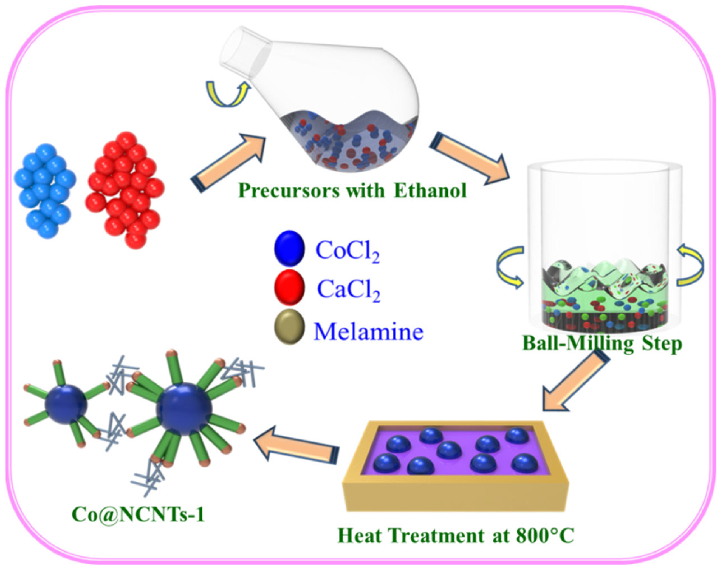
Abstract
:1. Introduction
2. Experimental Part
2.1. Reagents
2.2. Synthesis of Co@NCNTs, and NCNTs Nanomaterials
2.3. Characterization of Nanomaterials
2.4. Electrochemical Measurements
3. Results and Discussion
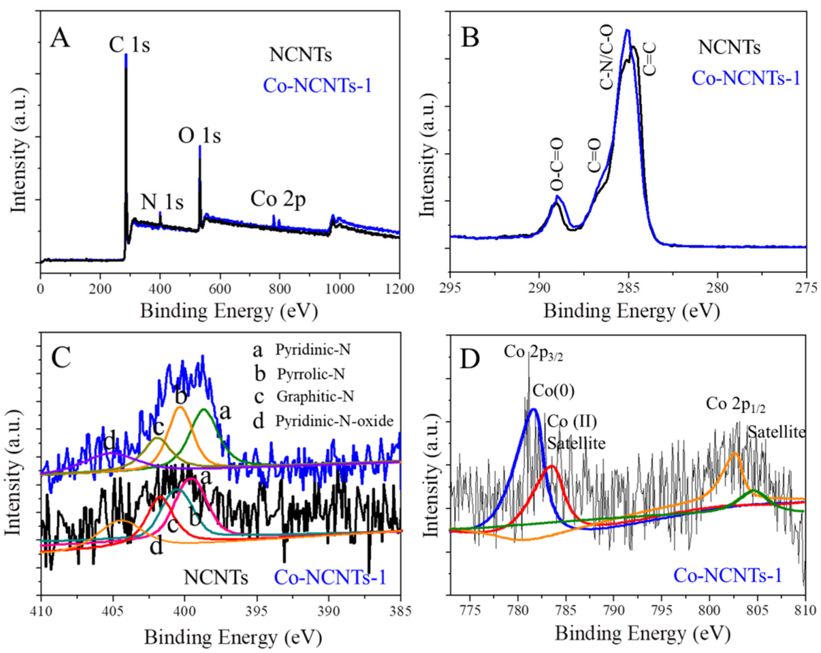
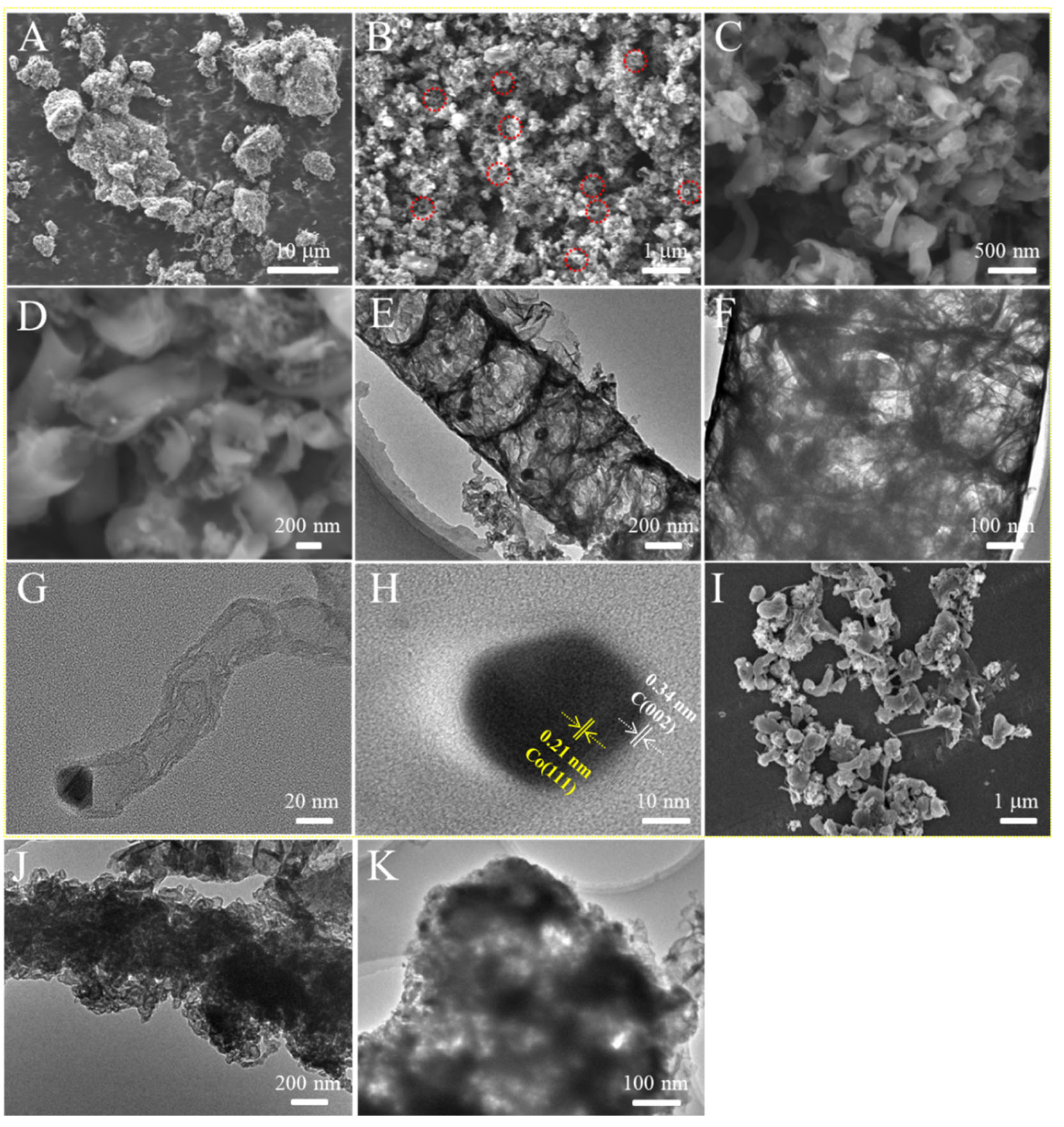
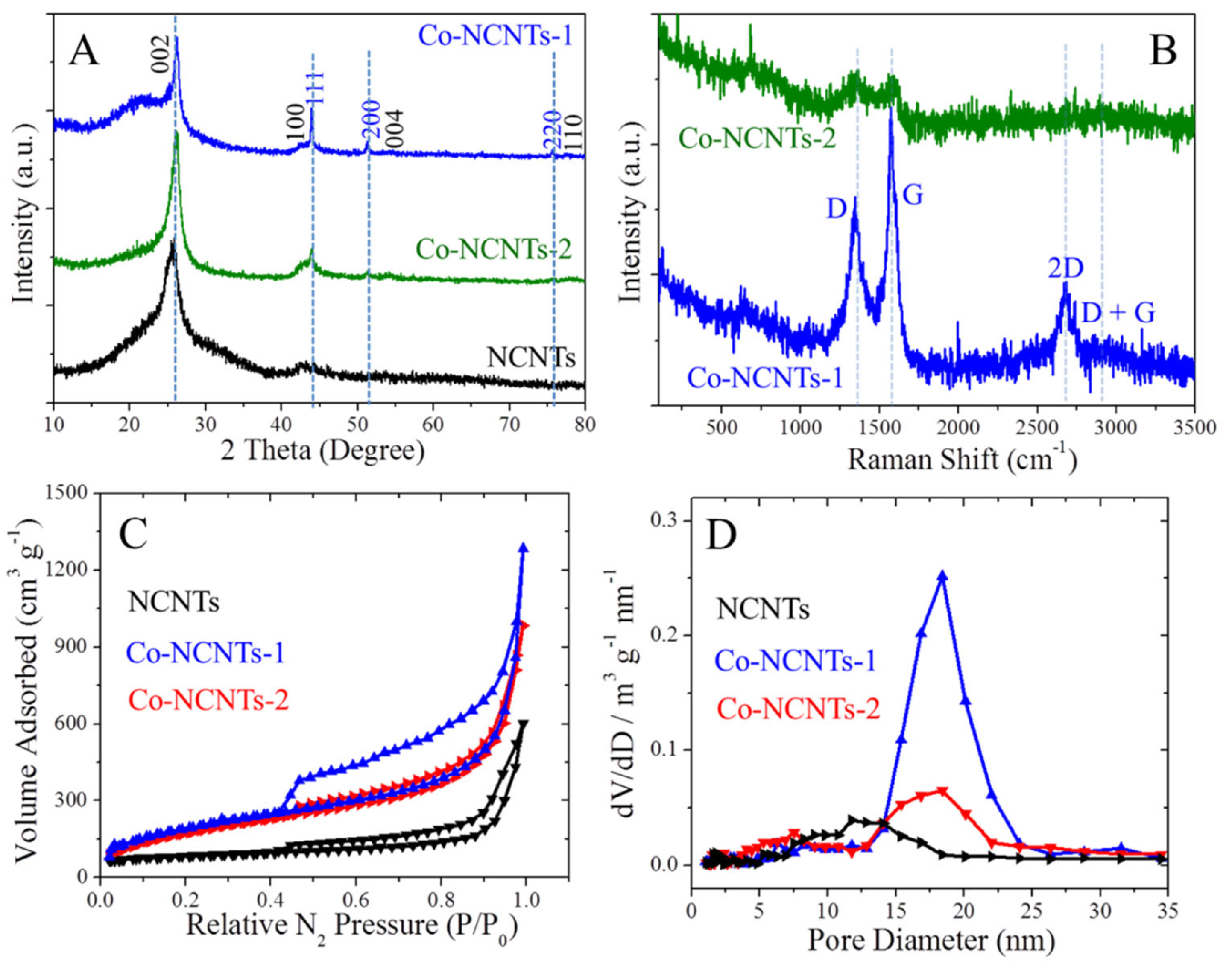
3.1. Characterization of Co@NCNTs Nanomaterials
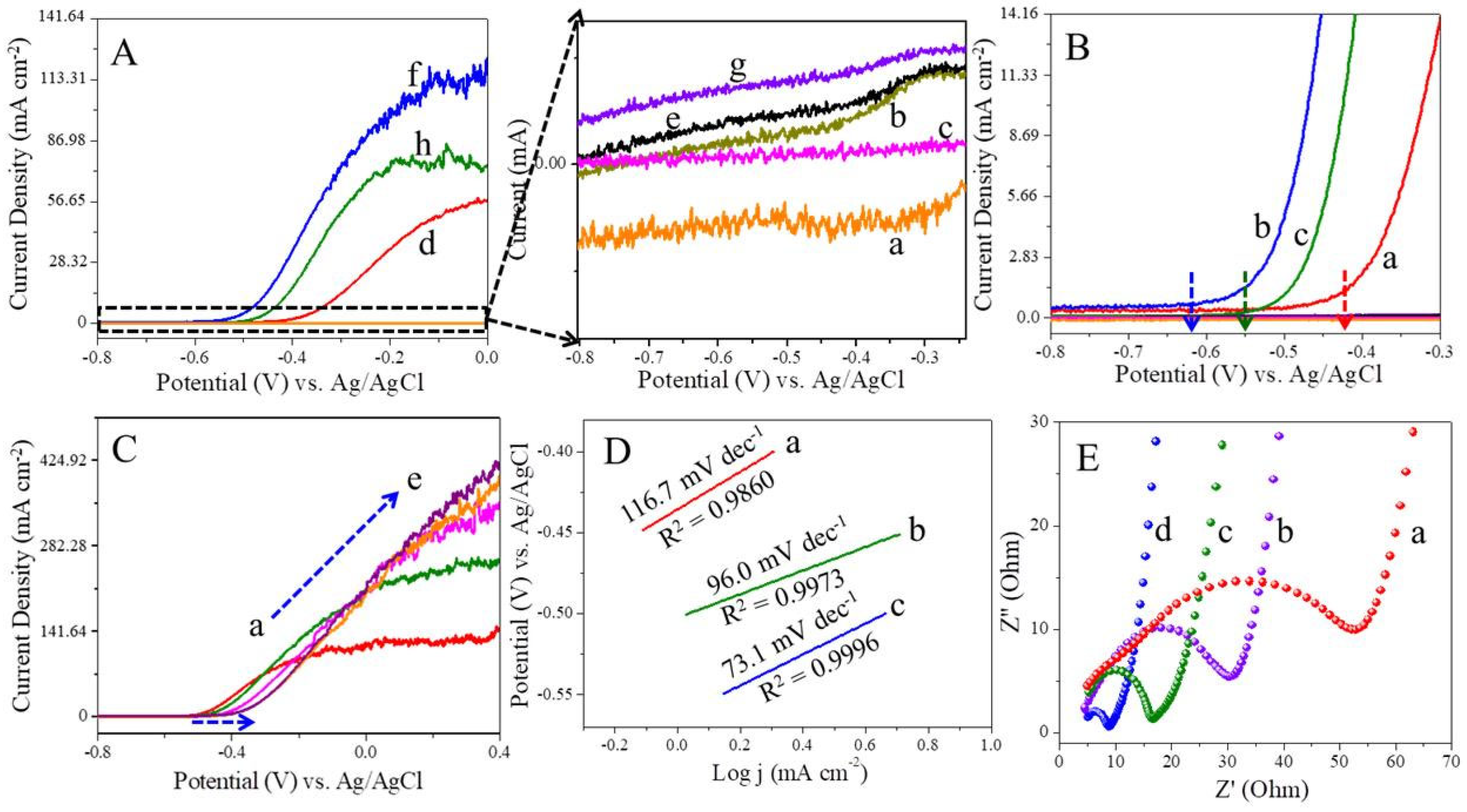
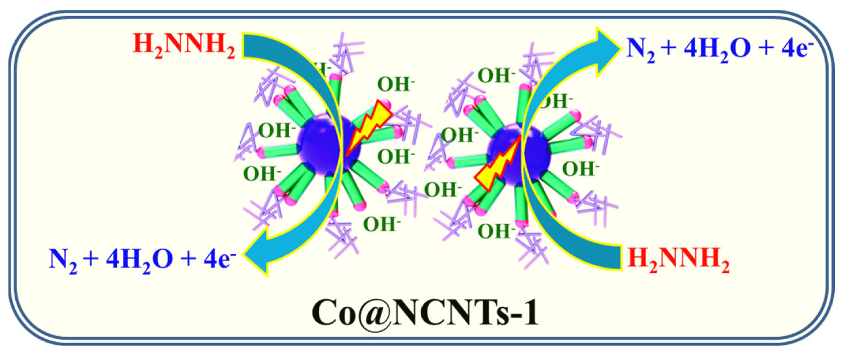
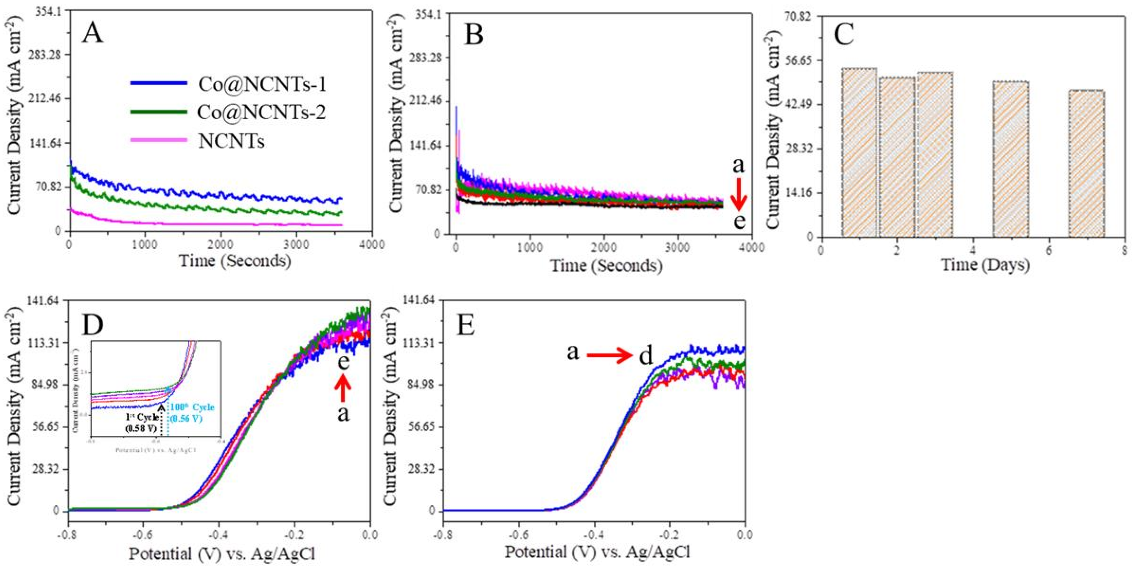
3.2. Electro-Oxidation of Hydrazine at NCNTs and Co@NCNTs
3.3. Amperometric Study of Hydrazine at NCNTs and Co@NCNTs
4. Conclusions
Supplementary Materials
Author Contributions
Funding
Institutional Review Board Statement
Informed Consent Statement
Conflicts of Interest
References
- Staffell, I.; Scamman, D.; Velazquez Abad, A.; Balcombe, P.; Dodds, P.E.; Ekins, P.; Shah, N.; Ward, K.R. The role of hydrogen and fuel cells in the global energy system. Energy Environ. Sci. 2019, 12, 463–491. [Google Scholar] [CrossRef] [Green Version]
- Shaari, N.; Kamarudin, S.K.; Bahru, R.; Osman, S.H.; Md Ishak, N.A.I. Progress and challenges: Review for direct liquid fuel cell. Int. J. Energy Res. 2021, 45, 6644–6688. [Google Scholar] [CrossRef]
- Yu, E.H.; Krewer, U.; Scott, K. Principles and Materials Aspects of Direct Alkaline Alcohol Fuel Cells. Energies 2010, 3, 1499–1528. [Google Scholar] [CrossRef]
- Ong, B.C.; Kamarudin, S.K.; Basri, S. Direct liquid fuel cells: A review. Int. J. Hydrogen Energy 2017, 42, 10142–10157. [Google Scholar] [CrossRef]
- Zakil, F.A.; Kamarudin, S.K.; Basri, S. Modified Nafion membranes for direct alcohol fuel cells: An overview. Renew. Sustain. Energy Rev. 2016, 65, 841–852. [Google Scholar] [CrossRef]
- Karim, N.A.; Alias, M.S.; Yang, H. Recent Developments for the Application of 3D Structured Material Nickel Foam and Graphene Foam in Direct Liquid Fuel Cells and Electrolyzers. Catalysts 2021, 11, 279. [Google Scholar] [CrossRef]
- Maduraiveeran, G. Nanoporous structured mixed transition metal oxides nanomaterials for electrochemical energy conversion technologies. Mater. Lett. 2021, 283, 128763. [Google Scholar] [CrossRef]
- Khalafallah, D.; Zhi, M.; Hong, Z. Development Trends on Nickel-Based Electrocatalysts for Direct Hydrazine Fuel Cells. ChemCatChem 2021, 13, 81–110. [Google Scholar] [CrossRef]
- Xie, Y.; Wang, Z.; Wang, H.; Lu, L.; Subramanian, P.; Ji, S.; Kannan, P. α-Co(OH)2 Thin-Layered Cactus-Like Nanostructures Wrapped Ni3S2 Nanowires: A Robust and Potential Catalyst for Electro-oxidation of Hydrazine. ChemElectroChem 2021, 8, 937–947. [Google Scholar] [CrossRef]
- Wang, H.; Ding, J.; Kannan, P.; Ji, S. Cobalt nanoparticles intercalated nitrogen-doped mesoporous carbon nanosheet network as potential catalyst for electro-oxidation of hydrazine. Int. J. Hydrogen Energy 2020, 45, 19344–19356. [Google Scholar] [CrossRef]
- Jiang, H.; Wang, Z.; Kannan, P.; Wang, H.; Wang, R.; Subramanian, P.; Ji, S. Grain boundaries of Co(OH)2-Ni-Cu nanosheets on the cotton fabric substrate for stable and efficient electro-oxidation of hydrazine. Int. J. Hydrogen Energy 2019, 44, 24591–24603. [Google Scholar] [CrossRef]
- Ding, J.; Kannan, P.; Wang, P.; Ji, S.; Wang, H.; Liu, Q.; Gai, H.; Liu, F.; Wang, R. Synthesis of nitrogen-doped MnO/carbon network as an advanced catalyst for direct hydrazine fuel cells. J. Power Sources 2019, 413, 209–215. [Google Scholar] [CrossRef]
- Kumaran, R.; Boopathi, S.; Kundu, M.; Sasidharan, M.; Maduraiveeran, G. The morphology-dependent electrocatalytic activities of spinel-cobalt oxide nanomaterials for direct hydrazine fuel cell application. New J. Chem. 2018, 42, 13087–13095. [Google Scholar] [CrossRef]
- Sanabria-Chinchilla, J.; Asazawa, K.; Sakamoto, T.; Yamada, K.; Tanaka, H.; Strasser, P. Noble Metal-Free Hydrazine Fuel Cell Catalysts: EPOC Effect in Competing Chemical and Electrochemical Reaction Pathways. J. Am. Chem. Soc. 2011, 133, 5425–5431. [Google Scholar] [CrossRef]
- Wang, Y.; Liu, X.; Tan, T.; Ren, Z.; Lei, Z.; Wang, W. A phosphatized pseudo-core-shell Fe@Cu-P/C electrocatalyst for efficient hydrazine oxidation reaction. J. Alloys Compd. 2019, 787, 104–111. [Google Scholar] [CrossRef]
- Liu, X.; Li, Y.; Chen, N.; Deng, D.; Xing, X.; Wang, Y. Ni3S2@Ni foam 3D electrode prepared via chemical corrosion by sodium sulfide and using in hydrazine electro-oxidation. Electrochim. Acta 2016, 213, 730–739. [Google Scholar] [CrossRef]
- Yamazaki, S.-i.; Ioroi, T.; Tanimoto, K.; Yasuda, K.; Asazawa, K.; Yamaguchi, S.; Tanaka, H. Electrochemical oxidation of hydrazine derivatives by carbon-supported metalloporphyrins. J. Power Sources 2012, 204, 79–84. [Google Scholar] [CrossRef]
- Yi, Q.; Yu, W. Nanoporous gold particles modified titanium electrode for hydrazine oxidation. J. Electroanal. Chem. 2009, 633, 159–164. [Google Scholar] [CrossRef]
- Kim, J.D.; Choi, M.Y.; Choi, H.C. Graphene-oxide-supported Pt nanoparticles with high activity and stability for hydrazine electro-oxidation in a strong acidic solution. Appl. Surf. Sci. 2017, 420, 700–706. [Google Scholar] [CrossRef]
- Wang, J.; Khaniya, A.; Hu, L.; Beazley, M.J.; Kaden, W.E.; Feng, X. A bifunctional catalyst for efficient dehydrogenation and electro-oxidation of hydrazine. J. Mater. Chem. A 2018, 6, 18050–18056. [Google Scholar] [CrossRef]
- Miao, R.; Yang, M.; Compton, R.G. The Electro-oxidation of Hydrazine with Palladium Nanoparticle Modified Electrodes: Dissecting Chemical and Physical Effects: Catalysis, Surface Roughness, or Porosity? J. Phys. Chem. Lett. 2021, 12, 6661–6666. [Google Scholar] [CrossRef]
- Das, A.K.; Kim, N.H.; Pradhan, D.; Hui, D.; Lee, J.H. Electrochemical synthesis of palladium (Pd) nanorods: An efficient electrocatalyst for methanol and hydrazine electro-oxidation. Compos. Part B: Eng. 2018, 144, 11–18. [Google Scholar] [CrossRef]
- Roy, N.; Bhunia, K.; Terashima, C.; Fujishima, A.; Pradhan, D. Citrate-Capped Hybrid Au-TiO2 Nanomaterial for Facile and Enhanced Electrochemical Hydrazine Oxidation. ACS Omega 2017, 2, 1215–1221. [Google Scholar] [CrossRef] [PubMed]
- Hosseini, M.; Momeni, M.M.; Faraji, M. Electro-oxidation of hydrazine on gold nanoparticles supported on TiO2 nanotube matrix as a new high active electrode. J. Mol. Catal. A Chem. 2011, 335, 199–204. [Google Scholar] [CrossRef]
- Gao, G.; Guo, D.; Wang, C.; Li, H. Electrocrystallized Ag nanoparticle on functional multi-walled carbon nanotube surfaces for hydrazine oxidation. Electrochem. Commun. 2007, 9, 1582–1586. [Google Scholar] [CrossRef]
- De Oliveira, D.C.; Silva, W.O.; Chatenet, M.; Lima, F.H.B. NiOx-Pt/C nanocomposites: Highly active electrocatalysts for the electrochemical oxidation of hydrazine. Appl. Catal. B Environ. 2017, 201, 22–28. [Google Scholar] [CrossRef]
- Wang, Y.; Liu, X.; Han, J.; Kang, Y.; Mi, Y.; Wang, W. Phosphatized pseudo-core-shell Ni@Pt/C electrocatalysts for efficient hydrazine oxidation reaction. Int. J. Hydrogen Energy 2020, 45, 6360–6368. [Google Scholar] [CrossRef]
- Al-Thubaiti, K.S.; Khan, Z. Trimetallic nanocatalysts to enhanced hydrogen production from hydrous hydrazine: The role of metal centers. Int. J. Hydrogen Energy 2020, 45, 13960–13974. [Google Scholar] [CrossRef]
- Park, J.; Bae, S.; Park, J.-S.; Bong, S.; Lee, J. Crusty-Structured Cu@NiCo Nanoparticles as Anode Catalysts in Alkaline Fuel Cells. ACS Appl. Nano Mater. 2021, 4, 8145–8153. [Google Scholar] [CrossRef]
- Sakamoto, T.; Masuda, T.; Yoshimoto, K.; Kishi, H.; Yamaguchi, S.; Matsumura, D.; Tamura, K.; Hori, A.; Horiuchi, Y.; Serov, A.; et al. NiO/Nb2O5/C Hydrazine Electrooxidation Catalysts for Anion Exchange Membrane Fuel Cells. J. Electrochem. Soc. 2017, 164, F229–F234. [Google Scholar] [CrossRef]
- Yang, H.; Zhong, X.; Dong, Z.; Wang, J.; Jin, J.; Ma, J. A highly active hydrazine fuel cell catalyst consisting of a Ni–Fe nanoparticle alloy plated on carbon materials by pulse reversal. RSC Adv. 2012, 2, 5038–5040. [Google Scholar] [CrossRef]
- Wang, W.; Wang, Y.; Liu, S.; Yahia, M.; Dong, Y.; Lei, Z. Carbon-supported phosphatized CuNi nanoparticle catalysts for hydrazine electrooxidation. Int. J. Hydrogen Energy 2019, 44, 10637–10645. [Google Scholar] [CrossRef]
- Liu, C.; Zhang, H.; Tang, Y.; Luo, S. Controllable growth of graphene/Cu composite and its nanoarchitecture-dependent electrocatalytic activity to hydrazine oxidation. J. Mater. Chem. A 2014, 2, 4580–4587. [Google Scholar] [CrossRef]
- Khilari, S.; Pradhan, D. MnFe2O4@nitrogen-doped reduced graphene oxide nanohybrid: An efficient bifunctional electrocatalyst for anodic hydrazine oxidation and cathodic oxygen reduction. Catal. Sci. Technol. 2017, 7, 5920–5931. [Google Scholar] [CrossRef]
- Gao, H.; Wang, Y.; Xiao, F.; Ching, C.B.; Duan, H. Growth of Copper Nanocubes on Graphene Paper as Free-Standing Electrodes for Direct Hydrazine Fuel Cells. J. Phys. Chem. C 2012, 116, 7719–7725. [Google Scholar] [CrossRef]
- Zhang, J.; Wang, Y.; Yang, C.; Chen, S.; Li, Z.; Cheng, Y.; Wang, H.; Xiang, Y.; Lu, S.; Wang, S. Elucidating the electro-catalytic oxidation of hydrazine over carbon nanotube-based transition metal single atom catalysts. Nano Res. 2021. [Google Scholar] [CrossRef]
- Dong, Q.; Wang, H.; Ji, S.; Wang, X.; Mo, Z.; Linkov, V.; Wang, R. Molten-Salt Media Synthesis of N-Doped Carbon Tubes Containing Encapsulated Co Nanoparticles as a Bifunctional Air Cathode for Zinc-Air Batteries. Chem. Eur. J. 2020, 26, 10752–10758. [Google Scholar] [CrossRef] [PubMed]
- Huang, T.; Chen, Y.; Lee, J.-M. A Microribbon Hybrid Structure of CoOx-MoC Encapsulated in N-Doped Carbon Nanowire Derived from MOF as Efficient Oxygen Evolution Electrocatalysts. Small 2017, 13, 1702753. [Google Scholar] [CrossRef]
- Xu, Y.; Deng, P.; Chen, G.; Chen, J.; Yan, Y.; Qi, K.; Liu, H.; Xia, B.Y. 2D Nitrogen-Doped Carbon Nanotubes/Graphene Hybrid as Bifunctional Oxygen Electrocatalyst for Long-Life Rechargeable Zn–Air Batteries. Adv. Funct. Mater. 2020, 30, 1906081. [Google Scholar] [CrossRef]
- Liu, Q.; Cao, S.; Qiu, Y. Effect of carbonization temperature on bimetallic FeCo-N/C nanofiber electrocatalysts for oxygen reduction reaction in sulfuric acid solution. Int. J. Hydrogen Energy 2017, 42, 29274–29282. [Google Scholar] [CrossRef]
- Ding, J.; Ji, S.; Wang, H.; Linkov, V.; Gai, H.; Liu, F.; Liu, Q.; Wang, R. N-Doped 3D Porous Ni/C Bifunctional Electrocatalysts for Alkaline Water Electrolysis. ACS Sustain. Chem. Eng. 2019, 7, 3974–3981. [Google Scholar] [CrossRef]
- Liu, S.; Amiinu, I.S.; Liu, X.; Zhang, J.; Bao, M.; Meng, T.; Mu, S. Carbon nanotubes intercalated Co/N-doped porous carbon nanosheets as efficient electrocatalyst for oxygen reduction reaction and zinc–air batteries. Chem. Eng. J. 2018, 342, 163–170. [Google Scholar] [CrossRef]
- Li, Y.; Li, F.-M.; Meng, X.-Y.; Li, S.-N.; Zeng, J.-H.; Chen, Y. Ultrathin Co3O4 Nanomeshes for the Oxygen Evolution Reaction. ACS Catal. 2018, 8, 1913–1920. [Google Scholar] [CrossRef]
- Yan, X.; Liu, Y.; Lan, J.; Yu, Y.; Murowchick, J.; Yang, X.; Peng, Z. Crystalline–amorphous Co@CoO core–shell heterostructures for efficient electro-oxidation of hydrazine. Mater. Chem. Front. 2018, 2, 96–101. [Google Scholar] [CrossRef]
- Sakamoto, T.; Kishi, H.; Yamaguchi, S.; Matsumura, D.; Tamura, K.; Hori, A.; Horiuchi, Y.; Serov, A.; Artyushkova, K.; Atanassov, P.; et al. Mechanism Study of Hydrazine Electrooxidation Reaction on Nickel Oxide Surface in Alkaline Electrolyte by In Situ XAFS. J. Electrochem. Soc. 2016, 163, H951–H957. [Google Scholar] [CrossRef]
- Feng, Z.; Li, D.; Wang, L.; Sun, Q.; Lu, P.; Xing, P.; An, M. In situ grown nanosheet NiZn alloy on Ni foam for high performance hydrazine electrooxidation. Electrochim. Acta 2019, 304, 275–281. [Google Scholar] [CrossRef]


Publisher’s Note: MDPI stays neutral with regard to jurisdictional claims in published maps and institutional affiliations. |
© 2021 by the authors. Licensee MDPI, Basel, Switzerland. This article is an open access article distributed under the terms and conditions of the Creative Commons Attribution (CC BY) license (https://creativecommons.org/licenses/by/4.0/).
Share and Cite
Wang, H.; Dong, Q.; Lei, L.; Ji, S.; Kannan, P.; Subramanian, P.; Yadav, A.P. Co Nanoparticle-Encapsulated Nitrogen-Doped Carbon Nanotubes as an Efficient and Robust Catalyst for Electro-Oxidation of Hydrazine. Nanomaterials 2021, 11, 2857. https://doi.org/10.3390/nano11112857
Wang H, Dong Q, Lei L, Ji S, Kannan P, Subramanian P, Yadav AP. Co Nanoparticle-Encapsulated Nitrogen-Doped Carbon Nanotubes as an Efficient and Robust Catalyst for Electro-Oxidation of Hydrazine. Nanomaterials. 2021; 11(11):2857. https://doi.org/10.3390/nano11112857
Chicago/Turabian StyleWang, Hui, Qing Dong, Lu Lei, Shan Ji, Palanisamy Kannan, Palaniappan Subramanian, and Amar Prasad Yadav. 2021. "Co Nanoparticle-Encapsulated Nitrogen-Doped Carbon Nanotubes as an Efficient and Robust Catalyst for Electro-Oxidation of Hydrazine" Nanomaterials 11, no. 11: 2857. https://doi.org/10.3390/nano11112857
APA StyleWang, H., Dong, Q., Lei, L., Ji, S., Kannan, P., Subramanian, P., & Yadav, A. P. (2021). Co Nanoparticle-Encapsulated Nitrogen-Doped Carbon Nanotubes as an Efficient and Robust Catalyst for Electro-Oxidation of Hydrazine. Nanomaterials, 11(11), 2857. https://doi.org/10.3390/nano11112857