On Nonlinear Bending Study of a Piezo-Flexomagnetic Nanobeam Based on an Analytical-Numerical Solution


Abstract
1. Introduction
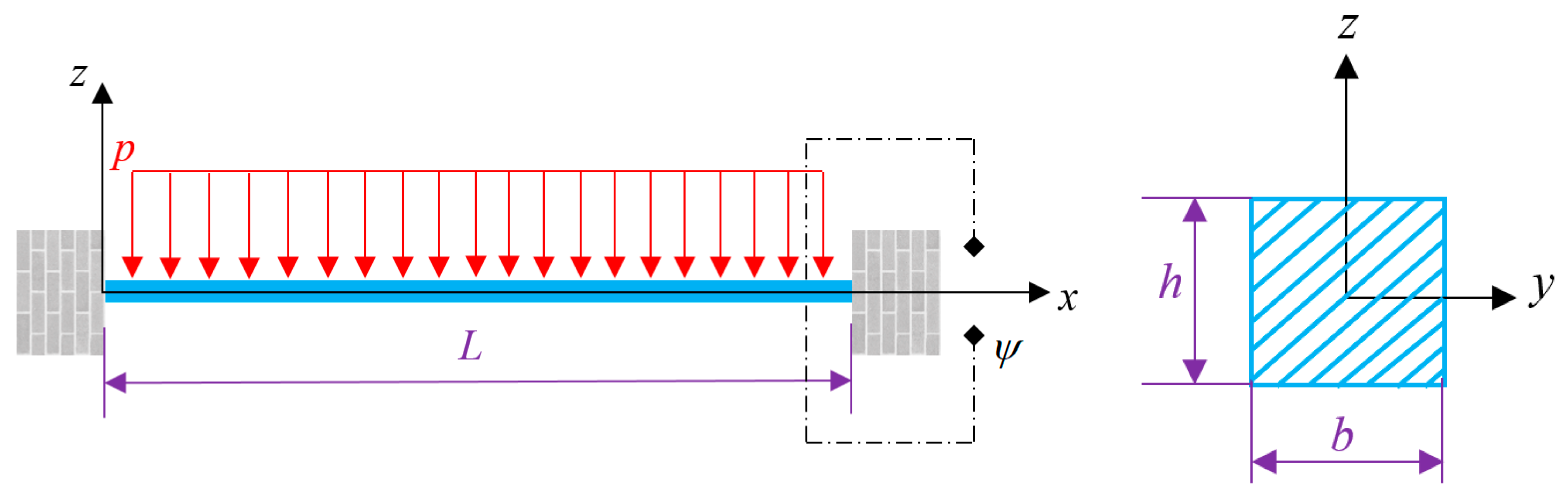
2. Mathematical Model
3. Solution Approach
4. Numerical Results and Discussion
4.1. Results’ Validity
4.2. Discussion of the Problem
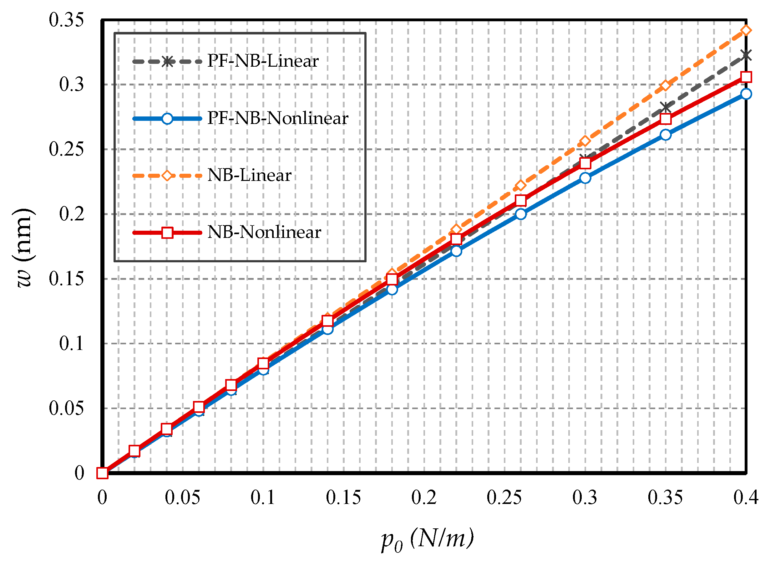
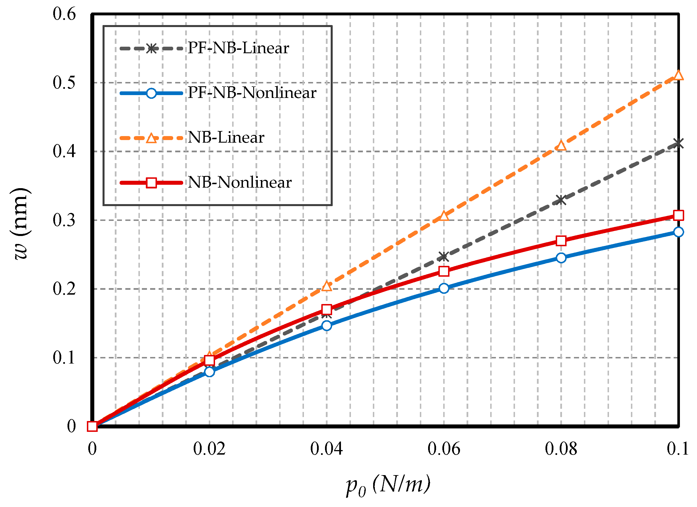
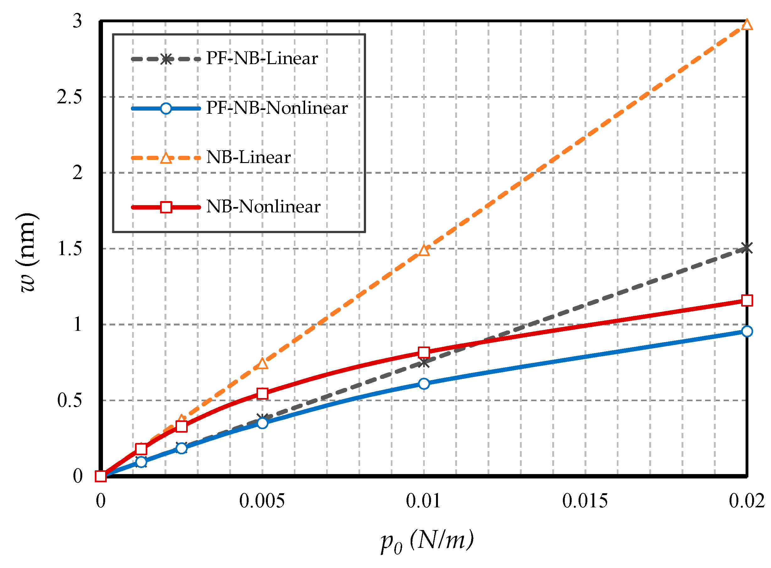
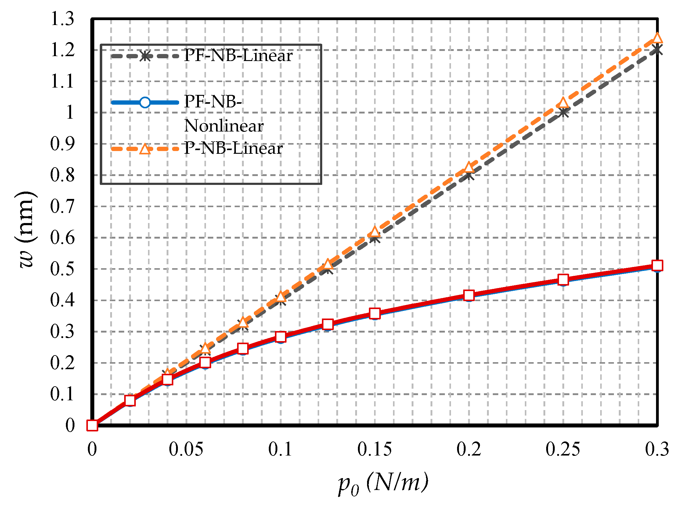
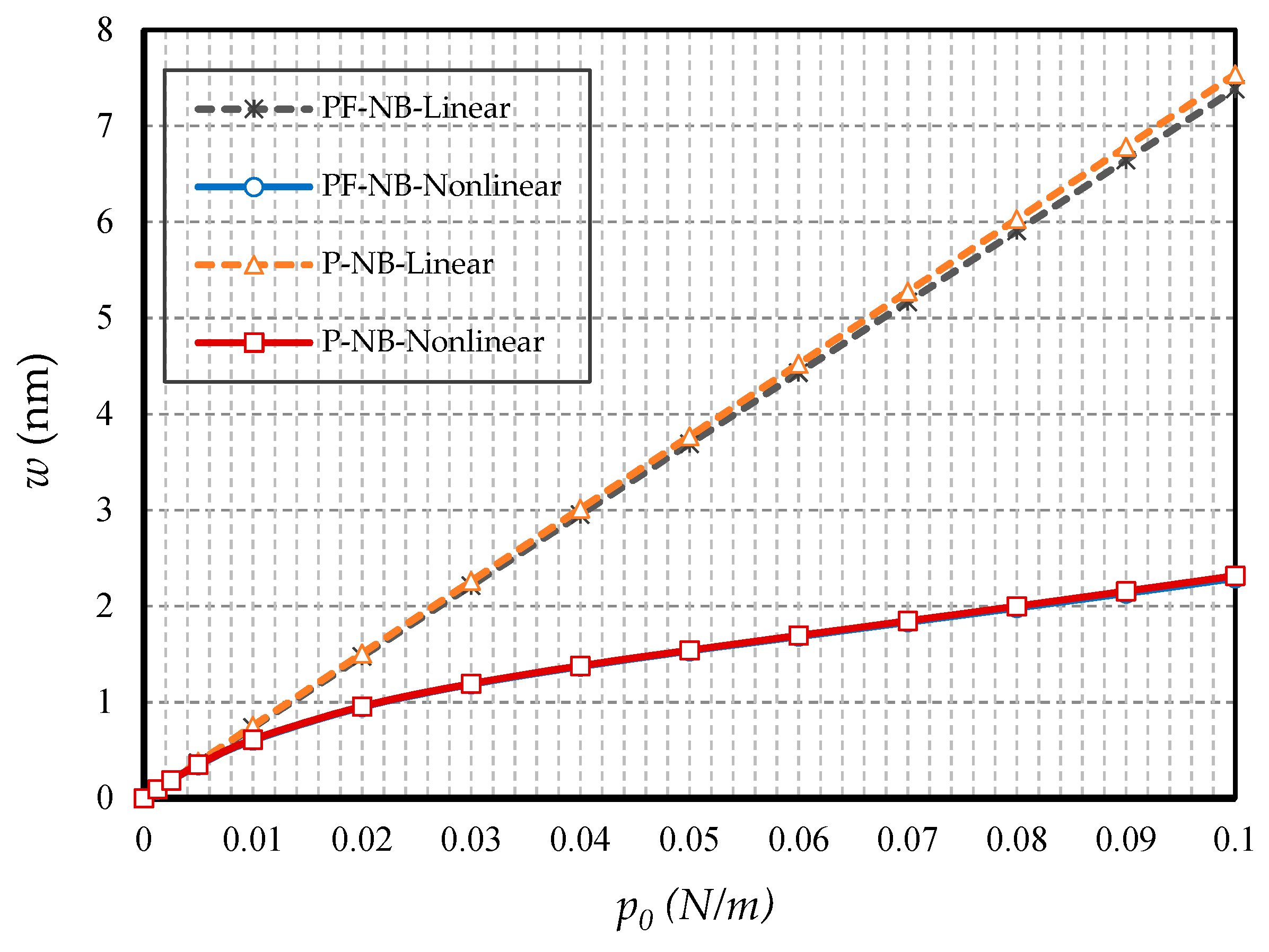
4.2.1. Effect of Nonlinearity
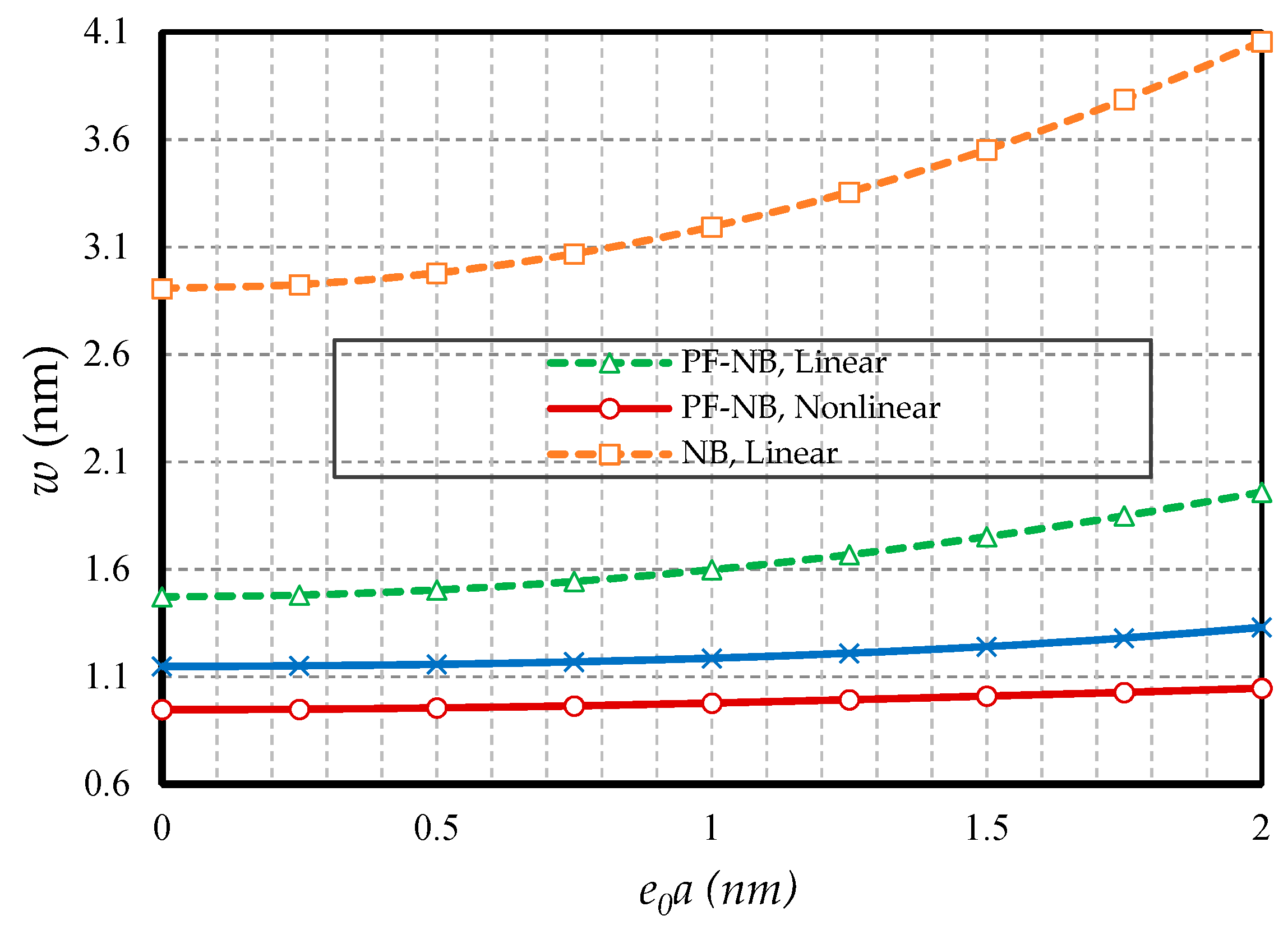
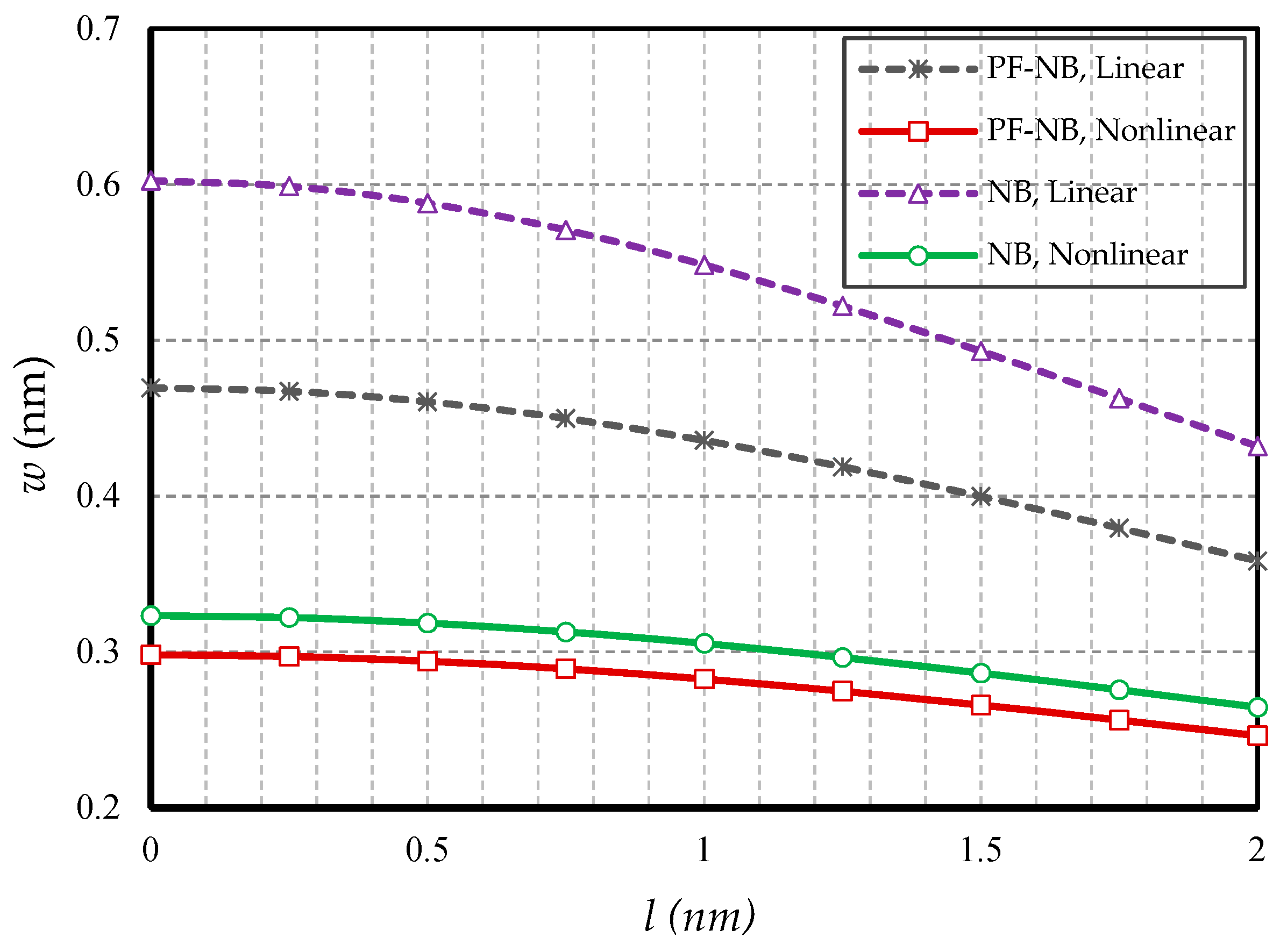
4.2.2. Effect of Small Scale
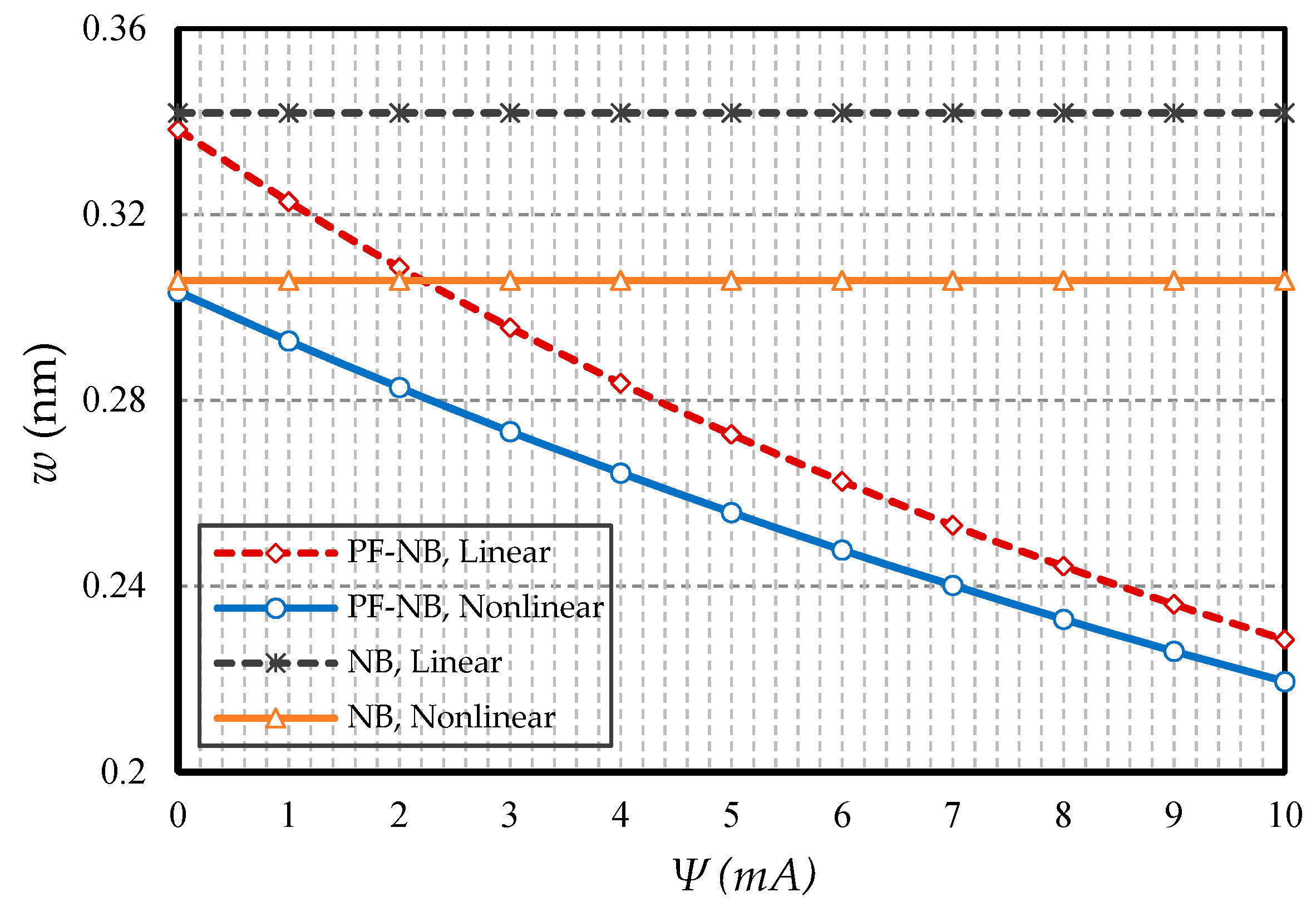
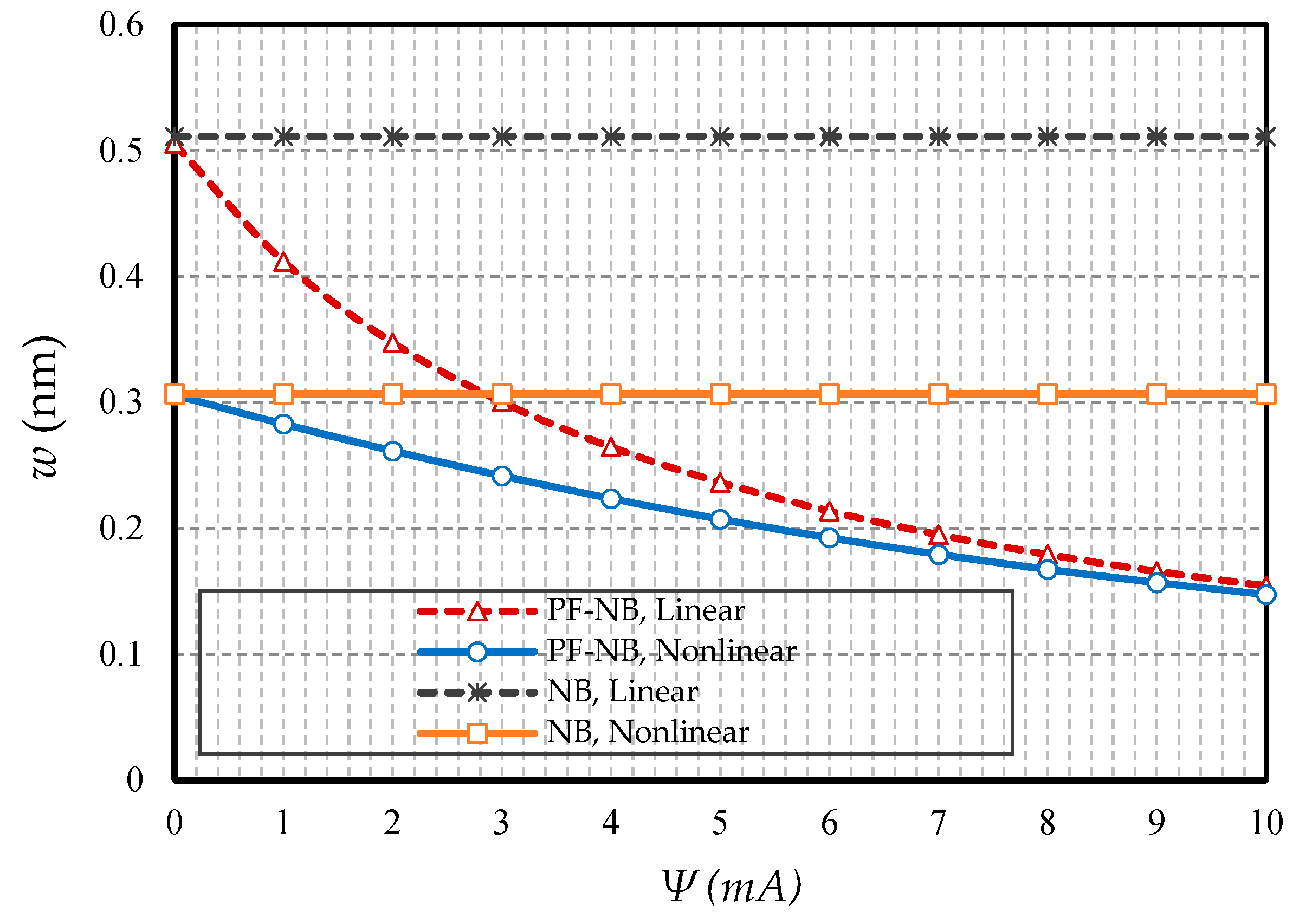
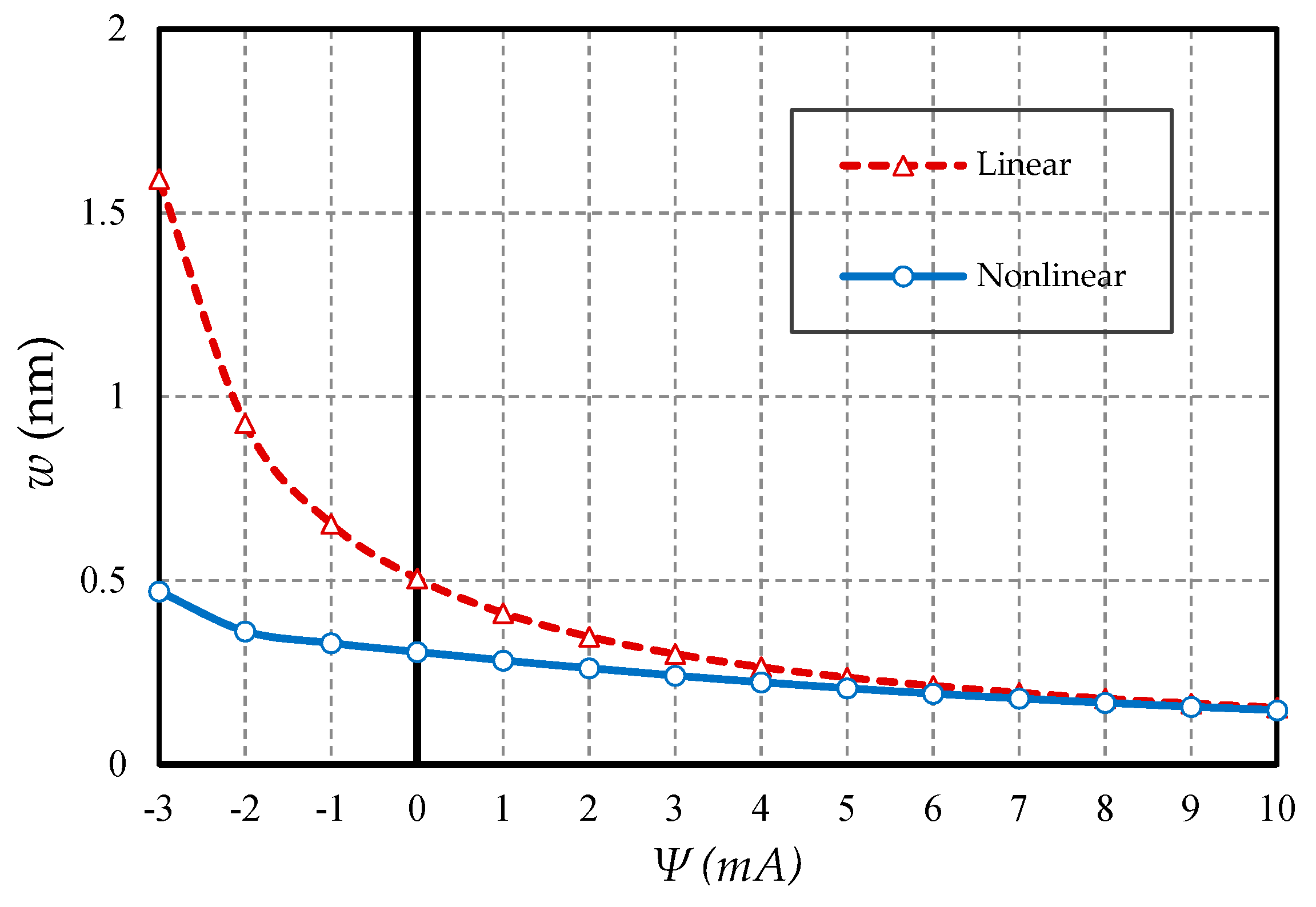
4.2.3. Effect of Magnetic Field
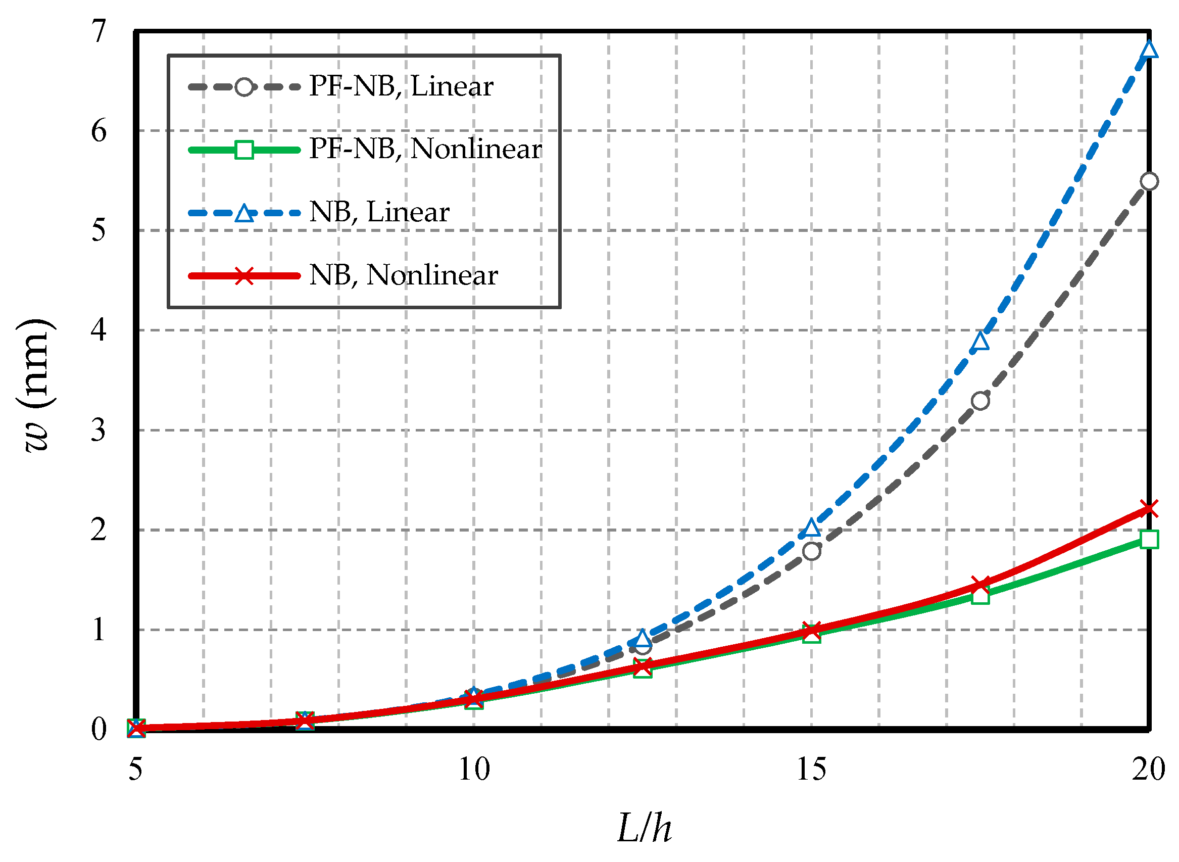
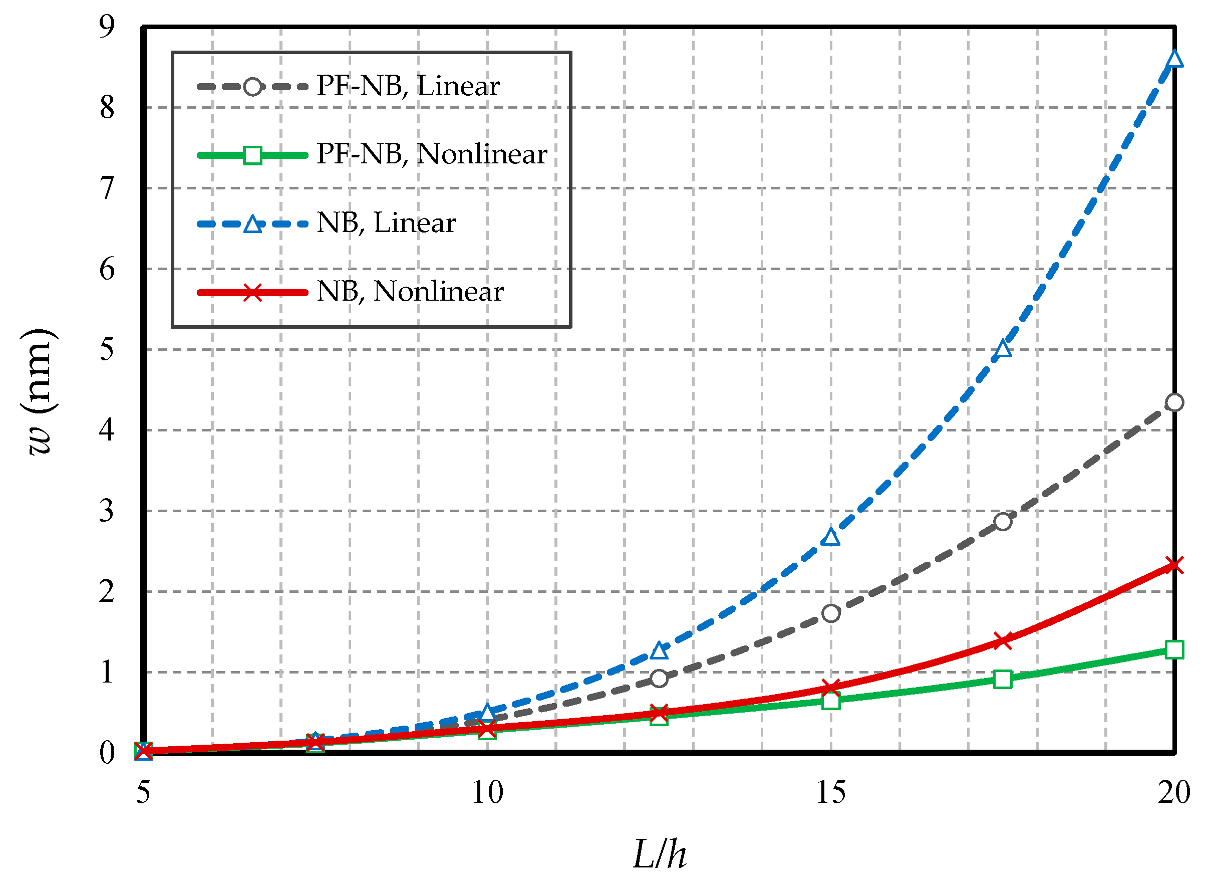
4.2.4. Effect of Slenderness Ratio
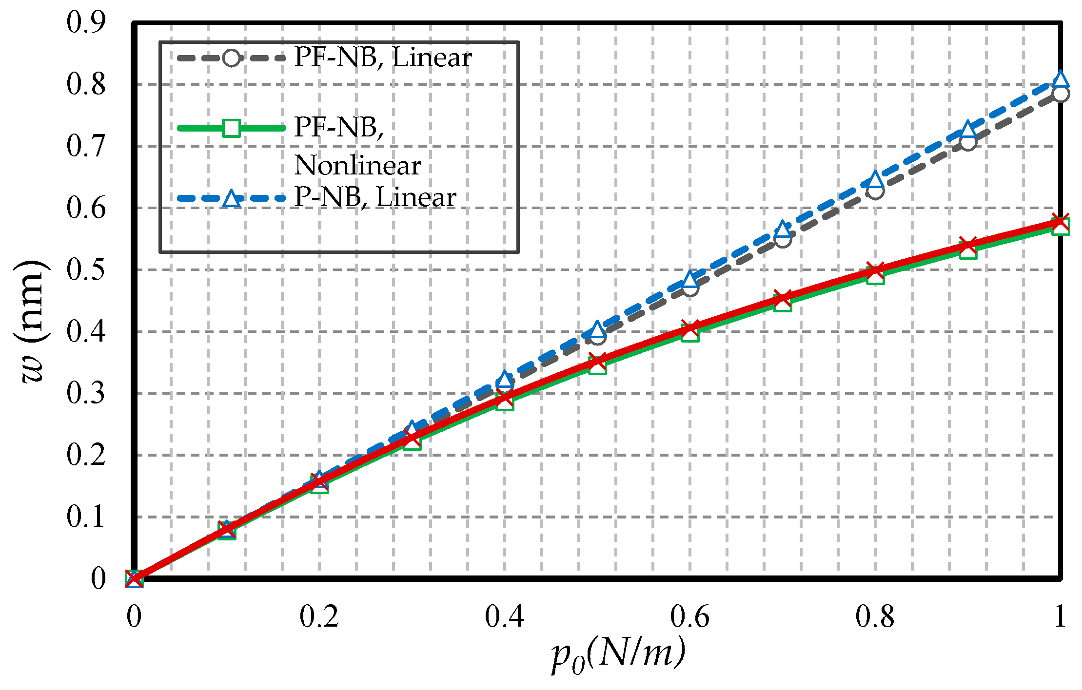
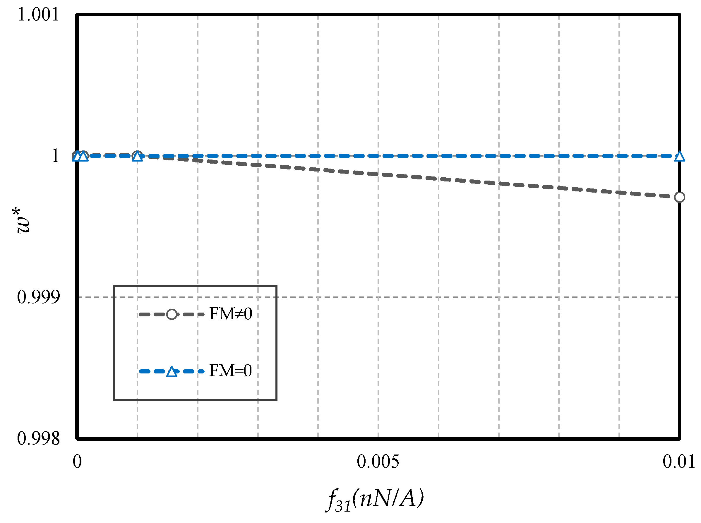
4.2.5. Effect of FM
5. Conclusions
- In hinged–hinged nanobeams, linear deflections for a NB can be used in the range w ≤ 0.1 h, and for a PF-NB, about w ≤ 0.08 h. This value in a double-fixed NB and PF-NB is in the range w < 0.15 h. However, for a cantilever case in NB, it is w ≤ 0.2 h and in PF-NB, it is w ≤ 0.1 h.
- The difference between the nonlinear analysis and the linear one will be more pronounced in the boundary condition with higher degrees of freedom.
- Increasing the numerical value of the nonlocal parameter leads to a softening effect on the material, and in contrast, increasing the numerical value of the strain gradient parameter leads to the appearance of stiffness in the material.
- The effect of nonlinear analysis is greater in large values of nonlocal parameters and small values of strain gradient parameters.
- The effect of nonlinear analysis on a nonlocal study is greater than a local one.
- The effect of nonlinear analysis in the positive magnetic field decreases. However, the opposite is true in the case of a negative magnetic field.
- For nanobeams with very large lengths, linear analysis gives entirely erroneous results even if the values of lateral loads are not large.
- The flexomagnetic effect leads to more material stiffness, and thus reduces the numerical values of deflections in static analysis.
- The less flexible the boundary condition, the higher the flexomagneticity effect.
Author Contributions
Funding
Conflicts of Interest
References
- Fahrner, W. Nanotechnology and Nanoelectronics, 1st ed.; Springer: Berlin, Germany, 2005; p. 269. [Google Scholar]
- Kabychenkov, A.F.; Lisovskii, F.V. Flexomagnetic and flexoantiferromagnetic effects in centrosymmetric antiferromagnetic materials. Tech. Phys. 2019, 64, 980–983. [Google Scholar] [CrossRef]
- Eliseev, E.A.; Morozovska, A.N.; Glinchuk, M.D.; Blinc, R. Spontaneous flexoelectric/flexomagnetic effect in nanoferroics. Phys. Rev. B 2009, 79, 165433. [Google Scholar] [CrossRef]
- Lukashev, P.; Sabirianov, R.F. Flexomagnetic effect in frustrated triangular magnetic structures. Phys. Rev. B 2010, 82, 094417. [Google Scholar] [CrossRef]
- Eliseev, E.A.; Morozovska, A.N.; Khist, V.V.; Polinger, V. Effective flexoelectric and flexomagnetic response of ferroics. In Recent Advances in Topological Ferroics and their Dynamics, Solid State Physics; Stamps, R.L., Schultheis, H., Eds.; Elsevier: London, UK, 2019; Volume 70, pp. 237–289. [Google Scholar]
- Zhang, J.X.; Zeches, R.J.; He, Q.; Chu, Y.H.; Ramesh, R. Nanoscale phase boundaries: A new twist to novel functionalities. Nanoscale 2012, 4, 6196–6204. [Google Scholar] [CrossRef] [PubMed]
- Zhou, H.; Pei, Y.; Fang, D. Magnetic field tunable small-scale mechanical properties of nickel single crystals measured by nanoindentation technique. Sci. Rep. 2014, 4, 1–6. [Google Scholar] [CrossRef]
- Ebrahimi, F.; Barati, M.R. Porosity-dependent vibration analysis of piezo-magnetically actuated heterogeneous nanobeams. Mech. Syst. Signal. Pr. 2017, 93, 445–459. [Google Scholar] [CrossRef]
- Zenkour, A.M.; Arefi, M.; Alshehri, N.A. Size-dependent analysis of a sandwich curved nanobeam integrated with piezomagnetic face-sheets. Results Phys. 2017, 7, 2172–2182. [Google Scholar] [CrossRef]
- Alibeigi, B.; Beni, Y.T. On the size-dependent magneto/electromechanical buckling of nanobeams. Eur. Phys. J. Plus 2018, 133, 398. [Google Scholar] [CrossRef]
- Malikan, M. Electro-mechanical shear buckling of piezoelectric nanoplate using modified couple stress theory based on simplified first order shear deformation theory. Appl. Math. Model. 2017, 48, 196–207. [Google Scholar] [CrossRef]
- Malikan, M.; Krasheninnikov, M.; Eremeyev, V.A. Torsional stability capacity of a nano-composite shell based on a nonlocal strain gradient shell model under a three-dimensional magnetic field. Int. J. Eng. Sci. 2020, 148, 103210. [Google Scholar] [CrossRef]
- Sidhardh, S.; Ray, M.C. Flexomagnetic response of nanostructures. J. Appl. Phys. 2018, 124, 244101. [Google Scholar] [CrossRef]
- Zhang, N.; Zheng, S.; Chen, D. Size-dependent static bending of flexomagnetic nanobeams. J. Appl. Phys. 2019, 126, 223901. [Google Scholar] [CrossRef]
- Malikan, M.; Eremeyev, V.A. Free Vibration of Flexomagnetic Nanostructured Tubes Based on Stress-driven Nonlocal Elasticity. In Analysis of Shells, Plates, and Beams, 1st ed.; Altenbach, H., Chinchaladze, N., Kienzler, R., Müller, W.H., Eds.; Springer Nature: Basel, Switzerland, 2020; Volume 134, pp. 215–226. [Google Scholar]
- Song, X.; Li, S.-R. Thermal buckling and post-buckling of pinned–fixed Euler–Bernoulli beams on an elastic foundation. Mech. Res. Commun. 2007, 34, 164–171. [Google Scholar] [CrossRef]
- Reddy, J.N. Nonlocal nonlinear formulations for bending of classical and shear deformation theories of beams and plates. Int. J. Eng. Sci. 2010, 48, 1507–1518. [Google Scholar] [CrossRef]
- Fernández-Sáez, J.; Zaera, R.; Loya, J.A.; Reddy, J.N. Bending of Euler–Bernoulli beams using Eringen’s integral formulation: A paradox resolved. Int. J. Eng. Sci. 2016, 99, 107–116. [Google Scholar] [CrossRef]
- Feo, L.; Penna, R. On Bending of Bernoulli-Euler Nanobeams for Nonlocal Composite Materials. Model. Simul. Eng. 2016. [Google Scholar] [CrossRef]
- Ghannadpour, S. Ritz Method Application to Bending, Buckling and Vibration Analyses of Timoshenko Beams via Nonlocal Elasticity. J. Appl. Comput. Mech. 2018, 4, 16–26. [Google Scholar]
- Demir, C.; Mercan, K.; Numanoglu, H.; Civalek, O. Bending Response of Nanobeams Resting on Elastic Foundation. J. Appl. Comput. Mech. 2018, 4, 105–114. [Google Scholar]
- Jia, N.; Yao, Y.; Yang, Y.; Chen, S. Size effect in the bending of a Timoshenko nanobeam. Acta Mech. 2017, 228, 2363–2375. [Google Scholar] [CrossRef]
- Marotti de Sciarra, F.; Barretta, R. A new nonlocal bending model for Euler–Bernoulli nanobeams. Mech Res. Commun. 2014, 62, 25–30. [Google Scholar] [CrossRef]
- Zenkour, A.M.; Sobhy, M. A simplified shear and normal deformations nonlocal theory for bending of nanobeams in thermal environment. Phys. E 2015, 70, 121–128. [Google Scholar] [CrossRef]
- Yang, L.; Fan, T.; Yang, L.; Han, X.; Chen, Z. Bending of functionally graded nanobeams incorporating surface effects based on Timoshenko beam model. Theor. Appl. Mech. Lett. 2017, 7, 152–158. [Google Scholar] [CrossRef]
- Lim, C.W.; Zhang, G.; Reddy, J.N. A Higher-order nonlocal elasticity and strain gradient theory and Its Applications in wave propagation. J. Mech. Phys. Solids 2015, 78, 298–313. [Google Scholar] [CrossRef]
- Şimşek, M. Some closed-form solutions for static, buckling, free and forced vibration of functionally graded (FG) nanobeams using nonlocal strain gradient theory. Compos. Struct. 2019, 224, 111041. [Google Scholar] [CrossRef]
- Karami, B.; Janghorban, M. On the dynamics of porous nanotubes with variable material properties and variable thickness. Int. J. Eng. Sci. 2019, 136, 53–66. [Google Scholar] [CrossRef]
- Sahmani, S.; Safaei, B. Nonlinear free vibrations of bi-directional functionally graded micro/nano-beams including nonlocal stress and microstructural strain gradient size effects. Thin Wall. Struct. 2019, 140, 342–356. [Google Scholar] [CrossRef]
- Karami, B.; Janghorban, M.; Rabczuk, T. Dynamics of two-dimensional functionally graded tapered Timoshenko nanobeam in thermal environment using nonlocal strain gradient theory. Compos. Part B-Eng. 2020, 182, 107622. [Google Scholar] [CrossRef]
- Malikan, M.; Dimitri, R.; Tornabene, F. Transient response of oscillated carbon nanotubes with an internal and external damping. Compos. Part B-Eng. 2019, 158, 198–205. [Google Scholar] [CrossRef]
- Malikan, M.; Eremeyev, V.A. On the dynamics of a visco-piezo-flexoelectric nanobeam. Symmetry 2020, 12, 643. [Google Scholar] [CrossRef]
- Malikan, M.; Eremeyev, V.A. Post-critical buckling of truncated conical carbon nanotubes considering surface effects embedding in a nonlinear Winkler substrate using the Rayleigh-Ritz method. Mater. Res. Express 2020, 7, 025005. [Google Scholar] [CrossRef]
- Norouzzadeh, A.; Ansari, R.; Rouhi, H. Nonlinear Bending Analysis of Nanobeams Based on the Nonlocal Strain Gradient Model Using an Isogeometric Finite Element Approach. IJST-T Civ. Eng. 2019, 43, 533–547. [Google Scholar] [CrossRef]
- Hashemian, M.; Foroutan, S.; Toghraie, D. Comprehensive beam models for buckling and bending behavior of simple nanobeam based on nonlocal strain gradient theory and surface effects. Mech. Mater. 2019, 139, 103209. [Google Scholar] [CrossRef]
- Malikan, M.; Nguyen, V.B.; Tornabene, F. Damped forced vibration analysis of single-walled carbon nanotubes resting on viscoelastic foundation in thermal environment using nonlocal strain gradient theory. Eng. Sci. Technol. Int. J. 2018, 21, 778–786. [Google Scholar] [CrossRef]
- Ebrahimi, F.; Dabbagh, A.; Tornabene, F.; Civalek, O. Hygro-thermal effects on wave dispersion responses of magnetostrictive sandwich nanoplates. Adv. Nano Res. 2019, 7, 157–167. [Google Scholar]
- She, G.L.; Liu, H.B.; Karami, B. On resonance behavior of porous FG curved nanobeams. Steel Compos. Struct. 2020, 36, 179–186. [Google Scholar]
- Ansari, R.; Sahmani, S.; Arash, B. Nonlocal plate model for free vibrations of single-layered graphene sheets. Phys. Lett. A 2010, 375, 53–62. [Google Scholar] [CrossRef]
- Akbarzadeh Khorshidi, M. The material length scale parameter used in couple stress theories is not a material constant. Int. J. Eng. Sci. 2018, 133, 15–25. [Google Scholar] [CrossRef]
- Malikan, M.; Eremeyev, V.A. A new hyperbolic-polynomial higher-order elasticity theory for mechanics of thick FGM beams with imperfection in the material composition. Compos. Struct. 2020, 249, 112486. [Google Scholar] [CrossRef]
- Berrabah, H.M.; Tounsi, A.; Semmah, A.; Adda Bedia, E.A. Comparison of various refined nonlocal beam theories for bending, vibration and buckling analysis of nanobeams. Struct. Eng. Mech. 2013, 48, 351–365. [Google Scholar] [CrossRef]
- Ansari, R.; Sahmani, S. Bending behavior and buckling of nanobeams including surface stress effects corresponding to different beam theories. Int. J. Eng. Sci. 2011, 49, 1244–1255. [Google Scholar] [CrossRef]
- Dastjerdi, S.; Jabbarzadeh, M. Nonlinear bending analysis of bilayer orthotropic graphene sheets resting on Winkler–Pasternak elastic foundation based on non-local continuum mechanics. Compos. Part B-Eng. 2016, 87, 161–175. [Google Scholar] [CrossRef]
- Reddy, J.N.; Pang, S.D. Nonlocal continuum theories of beams for the analysis of carbon nanotubes. J. Appl. Phys. 2008, 103, 023511. [Google Scholar] [CrossRef]
- Ansari, R.; Sahmani, S.; Rouhi, H. Rayleigh–Ritz axial buckling analysis of single-walled carbon nanotubes with different boundary conditions. Phys. Lett. A 2011, 375, 1255–1263. [Google Scholar] [CrossRef]
- Duan, W.H.; Wang, C.M. Exact solutions for axisymmetric bending of micro/nanoscale circular plates based on nonlocal plate theory. Nanotechnology 2007, 18, 385704. [Google Scholar] [CrossRef]
- Duan, W.H.; Wang, C.M.; Zhang, Y.Y. Calibration of nonlocal scaling effect parameter for free vibration of carbon nanotubes by molecular dynamics. J. Appl. Phys. 2007, 101, 24305. [Google Scholar] [CrossRef]
- Maranganti, R.; Sharma, P. Length scales at which classical elasticity breaks down for various materials. Phys. Rev. Lett. 2007, 98, 195504. [Google Scholar] [CrossRef]
- Stein, C.R.; Bezerra, M.T.S.; Holanda, G.H.A.; André-Filho, J.; Morais, P.C. Structural and magnetic properties of cobalt ferrite nanoparticles synthesized by co-precipitation at increasing temperatures. AIP Advan. 2018, 8, 056303. [Google Scholar] [CrossRef]


| L/h | e0a/L | EBT, Linear [21] | EBT, Linear [45] | EBT, Linear [Present] |
|---|---|---|---|---|
| 10 | 0 | 0.013021 | 0.013021 | 0.013021 |
| 0.05 | 0.013333 | 0.013333 | 0.013333 | |
| 0.1 | 0.014271 | 0.014271 | 0.014271 | |
| 0.15 | 0.015833 | 0.015833 | 0.015833 |
| L/h | p (kN/mm) | EBT, Linear [Present] | FEM, Linear [ABAQUS] |
|---|---|---|---|
| 10 | 0.01 | 0.0792 | 0.0824 |
| 0.02 | 0.1585 | 0.1648 | |
| 0.03 | 0.2377 | 0.2472 | |
| 0.04 | 0.3170 | 0.3297 |
| CoFe2O4 |
|---|
| C11 = 286 GPa |
| q31 = 580.3 N/Ampere.m |
| a33 = 1.57 × 10⁻⁴ N/Ampere2 |
| L = 10 h |
© 2020 by the authors. Licensee MDPI, Basel, Switzerland. This article is an open access article distributed under the terms and conditions of the Creative Commons Attribution (CC BY) license (http://creativecommons.org/licenses/by/4.0/).
Share and Cite
Malikan, M.; Eremeyev, V.A. On Nonlinear Bending Study of a Piezo-Flexomagnetic Nanobeam Based on an Analytical-Numerical Solution. Nanomaterials 2020, 10, 1762. https://doi.org/10.3390/nano10091762
Malikan M, Eremeyev VA. On Nonlinear Bending Study of a Piezo-Flexomagnetic Nanobeam Based on an Analytical-Numerical Solution. Nanomaterials. 2020; 10(9):1762. https://doi.org/10.3390/nano10091762
Chicago/Turabian StyleMalikan, Mohammad, and Victor A. Eremeyev. 2020. "On Nonlinear Bending Study of a Piezo-Flexomagnetic Nanobeam Based on an Analytical-Numerical Solution" Nanomaterials 10, no. 9: 1762. https://doi.org/10.3390/nano10091762
APA StyleMalikan, M., & Eremeyev, V. A. (2020). On Nonlinear Bending Study of a Piezo-Flexomagnetic Nanobeam Based on an Analytical-Numerical Solution. Nanomaterials, 10(9), 1762. https://doi.org/10.3390/nano10091762