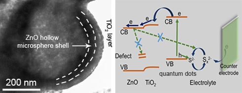
TiO2 Passivation Layer on ZnO Hollow Microspheres for Quantum Dots Sensitized Solar Cells with Improved Light Harvesting and Electron Collection

Abstract
1. Introduction
2. Materials and Methods
2.1. Materials
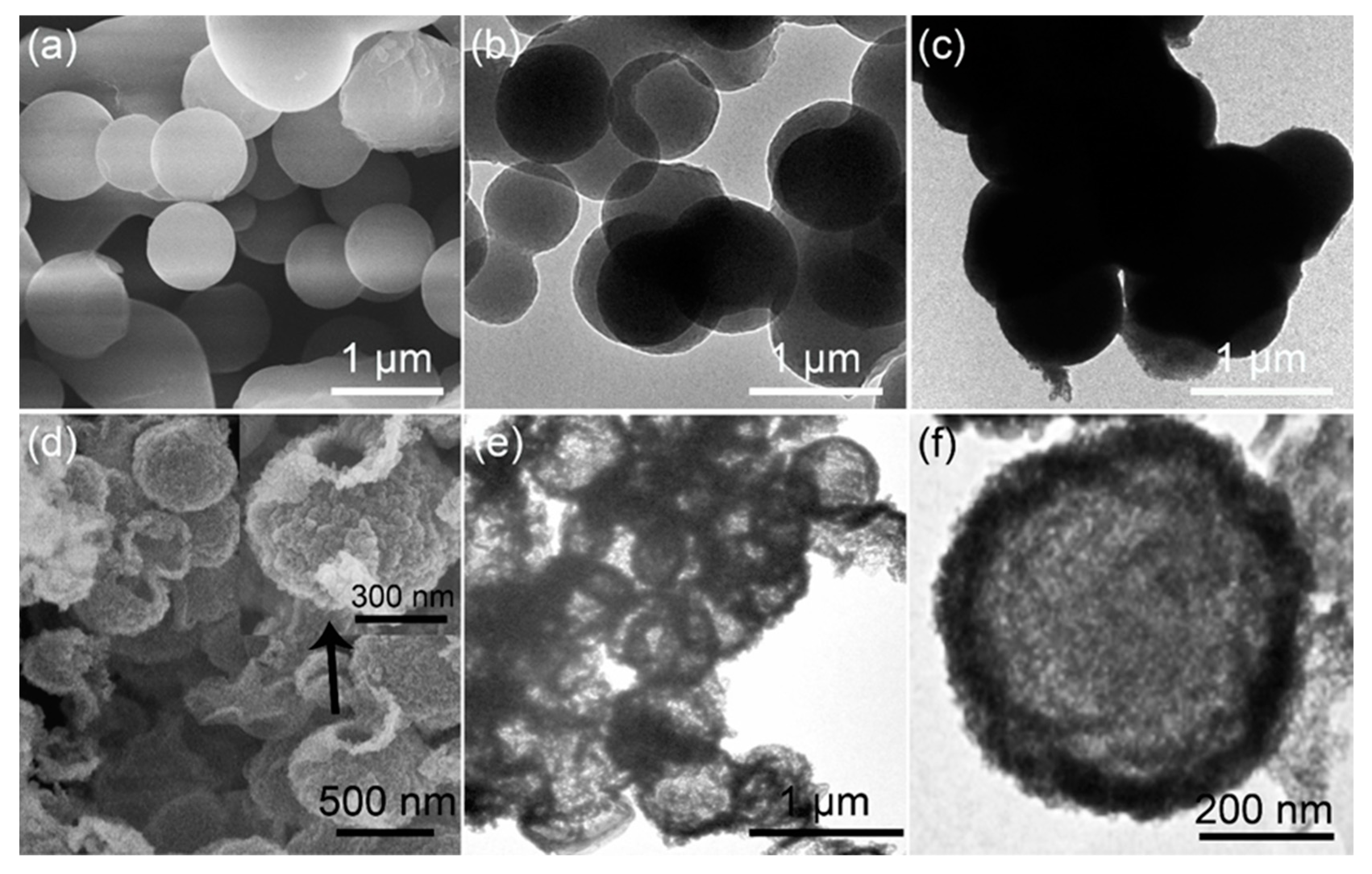
2.2. Preparation Carbonaceous Spheres Templates
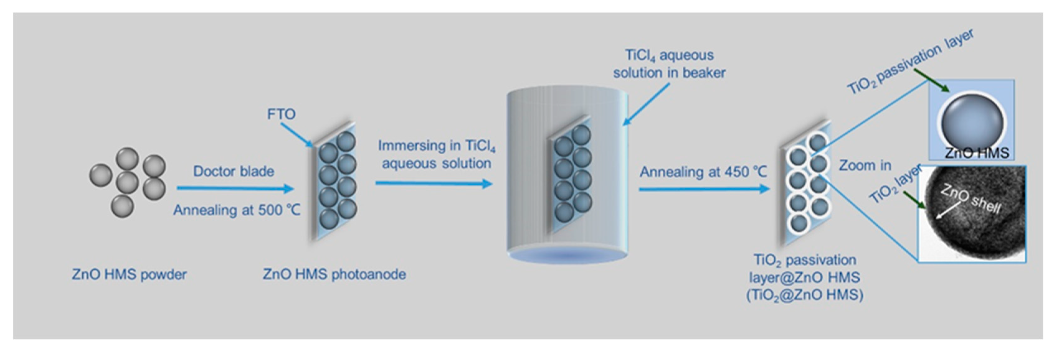
2.3. Synthesis of ZnO Hollow Microspheres (HMS) and Fabrication of ZnO HMS Photoanode
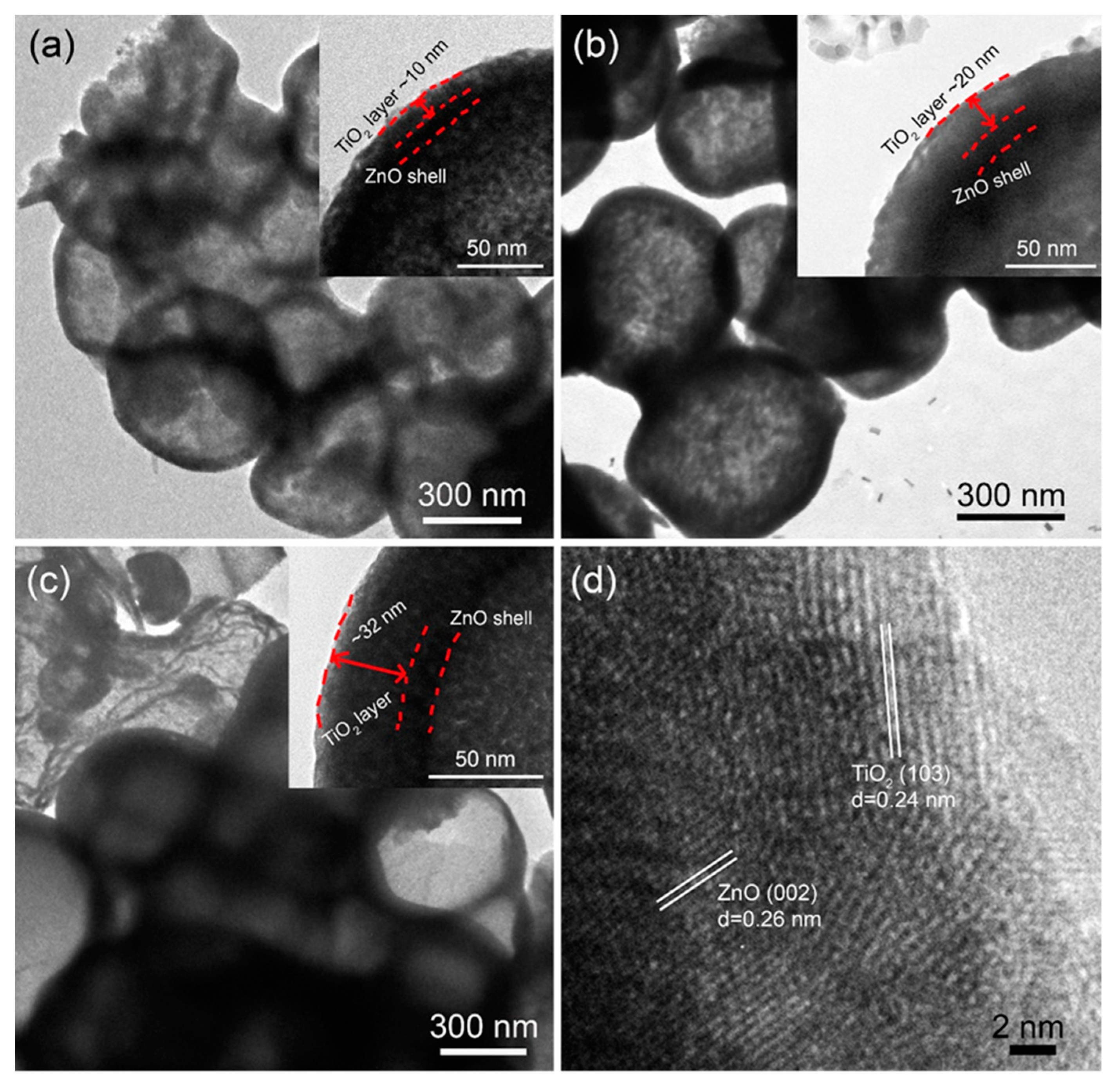
2.4. Fabrication of TiO2-Passivated ZnO Hollow Microspheres Photoanode
2.5. Assemble of ZnS/CdSe/CdS Quantum Dots Sensitized Solar Cells
2.6. Characterization
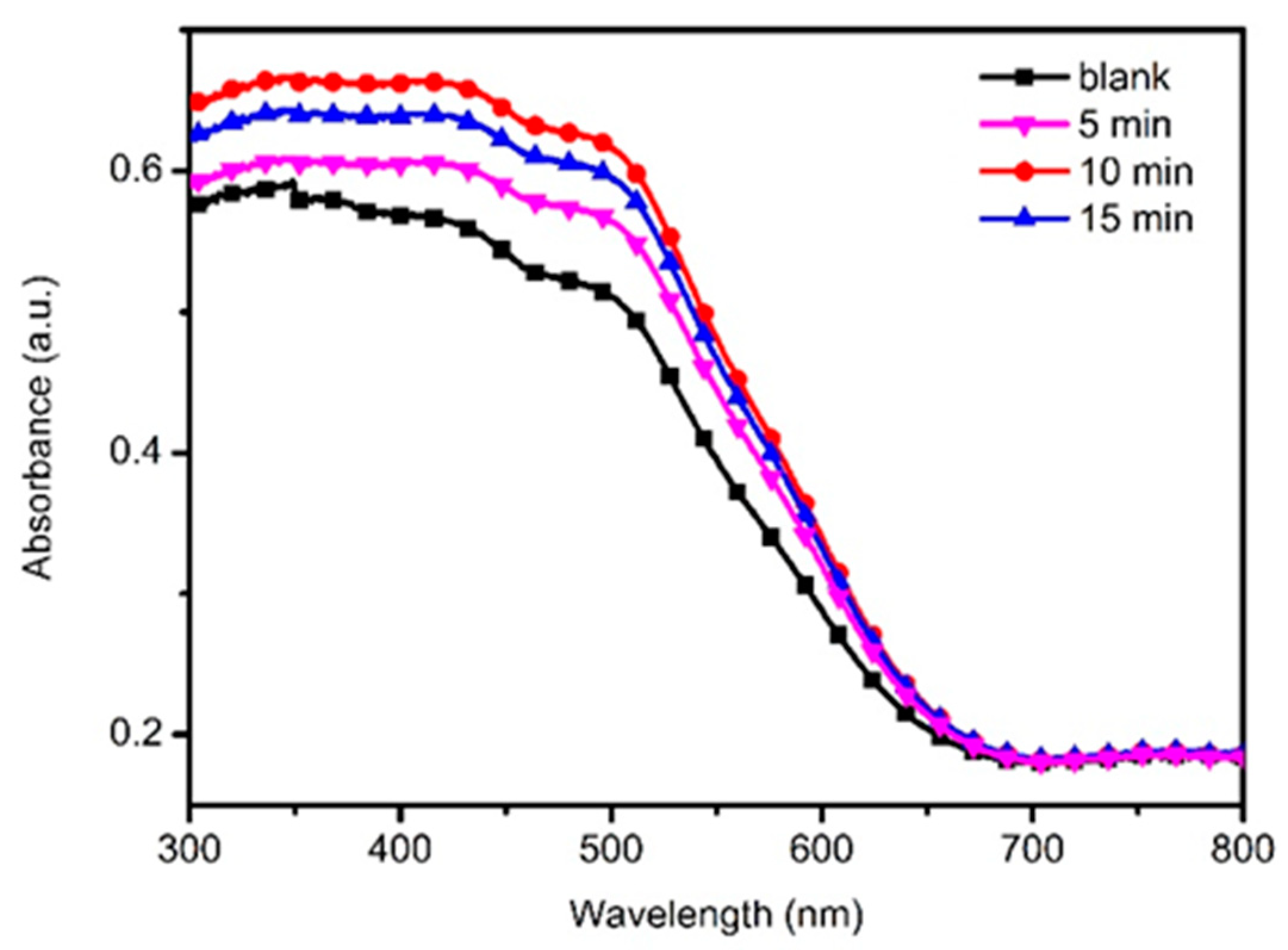
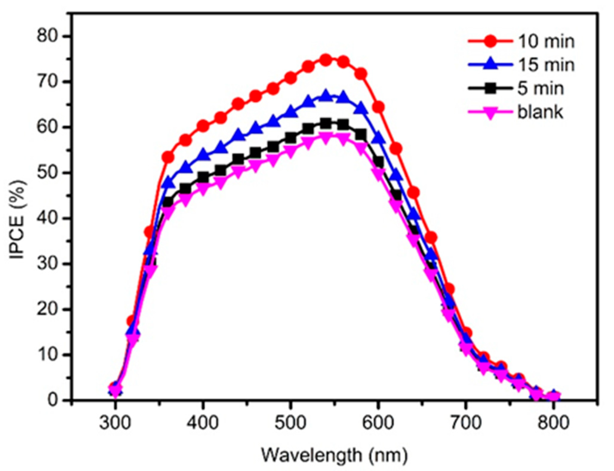
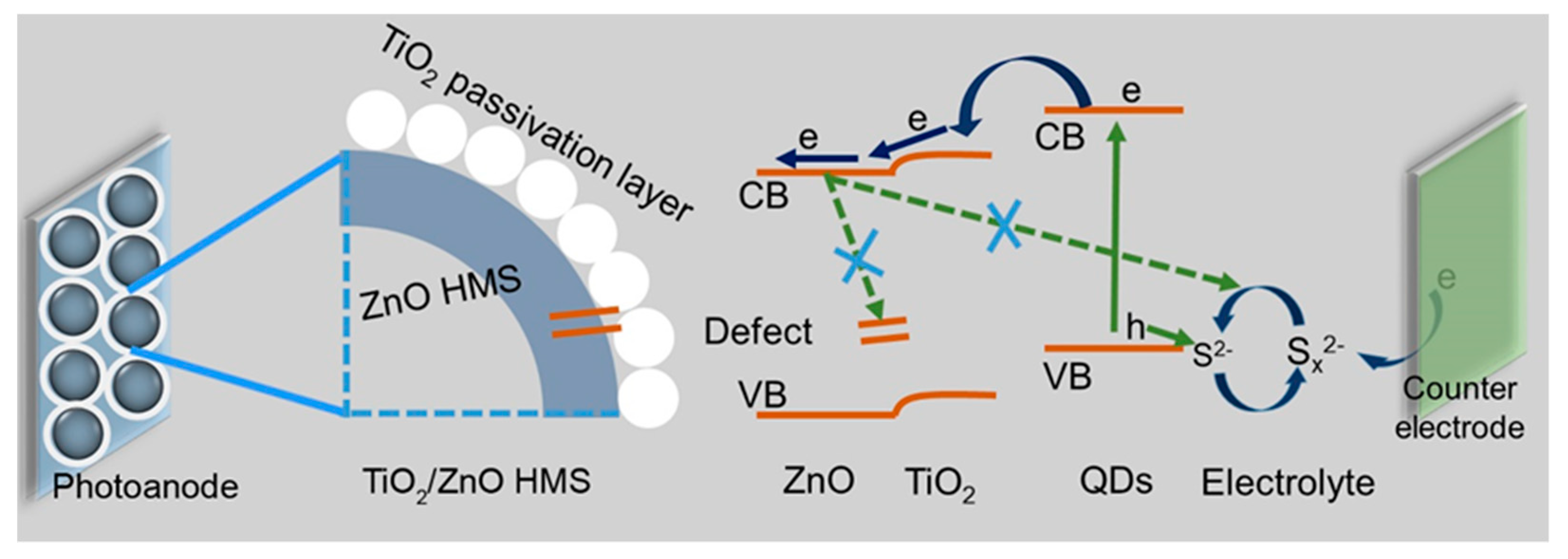
3. Results and Discussion
4. Conclusions
Supplementary Materials
Author Contributions
Funding
Conflicts of Interest
References
- Kim, H.-J.; Kim, H.-J.; Chebrolu, V.T. Recent progress in quantum dot sensitized solar cells: An inclusive review of photoanode, sensitizer, electrolyte, and the counter electrode. J. Mater. Chem. C 2019, 7, 4911–4933. [Google Scholar]
- Tian, J.; Cao, G. Semiconductor quantum dot-sensitized solar cells. Nano Rev. 2013, 4, 18737. [Google Scholar] [CrossRef] [PubMed]
- Su, D.S.; Centi, G. A perspective on carbon materials for future energy application. J. Energy Chem. 2013, 22, 151–173. [Google Scholar] [CrossRef]
- Yang, X.; Wang, H.; Cai, B.; Yu, Z.; Sun, L. Progress in hole-transporting materials for perovskite solar cells. J. Energy Chem. 2018, 27, 650–672. [Google Scholar] [CrossRef]
- Mu, L.; Liu, C.; Jia, J.; Zhou, X.; Lin, Y. Dual post-treatment: A strategy towards high efficiency quantum dot sensitized solar cells. J. Mater. Chem. A 2013, 1, 8353–8357. [Google Scholar] [CrossRef]
- Wang, X.W.; Wang, Y.F.; Zeng, J.H.; Shi, F.; Chen, Y.; Jiang, J. Quantum dot sensitized solar cells: Light harvesting versus charge recombination, a film thickness consideration. Chem. Phys. Lett. 2017, 682, 71–76. [Google Scholar] [CrossRef]
- Manjceevan, A.; Bandara, J. Optimization of performance and stability of quantum dot sensitized solar cells by manipulating the electrical properties of different metal sulfide counter electrodes. Electrochim. Acta 2017, 235, 390–398. [Google Scholar] [CrossRef]
- Jun, H.; Careem, M.; Arof, A.K. Quantum dot-sensitized solar cells—Perspective and recent developments: A review of Cd chalcogenide quantum dots as sensitizers. Renew. Sustain. Energy Rev. 2013, 22, 148–167. [Google Scholar] [CrossRef]
- Rühle, S.; Shalom, M.; Zaban, A. Quantum-Dot-Sensitized Solar Cells. ChemPhysChem 2010, 11, 2290–2304. [Google Scholar] [CrossRef]
- Kouhnavard, M.; Ikeda, S.; Ludin, N.; Khairudin, N.A.; Ghaffari, B.V.; Mat-Teridi, M.; Ibrahim, M.A.; Sepeai, S.; Sopian, K. A review of semiconductor materials as sensitizers for quantum dot-sensitized solar cells. Renew. Sustain. Energy Rev. 2014, 37, 397–407. [Google Scholar] [CrossRef]
- Li, Z.; Wang, R.; Xue, J.; Xing, X.; Yu, C.; Huang, T.; Chu, J.; Wang, K.-L.; Dong, C.; Wei, Z.; et al. Core–Shell ZnO@SnO2 Nanoparticles for Efficient Inorganic Perovskite Solar Cells. J. Am. Chem. Soc. 2019, 141, 17610–17616. [Google Scholar] [CrossRef] [PubMed]
- Luan, C.; Vaneski, A.; Susha, A.; Xu, X.; Wang, H.-E.; Chen, X.; Xu, J.; Zhang, W.; Lee, C.-S.; Rogach, A.L.; et al. Facile solution growth of vertically aligned ZnO nanorods sensitized with aqueous CdS and CdSe quantum dots for photovoltaic applications. Nanoscale Res. Lett. 2011, 6, 340. [Google Scholar] [CrossRef] [PubMed][Green Version]
- Shen, G.; Du, Z.; Pan, Z.; Du, J.; Zhong, X. Solar Paint from TiO2 Particles Supported Quantum Dots for Photoanodes in Quantum Dot-Sensitized Solar Cells. ACS Omega 2018, 3, 1102–1109. [Google Scholar] [CrossRef] [PubMed]
- Huang, Q.; Li, F.; Gong, Y.; Luo, J.; Yang, S.; Luo, Y.; Li, N.; Bai, X.; Meng, Q. Recombination in SnO2-Based Quantum Dots Sensitized Solar Cells: The Role of Surface States. J. Phys. Chem. C 2013, 117, 10965–10973. [Google Scholar] [CrossRef]
- Li, L.-B.; Wu, W.-Q.; Rao, H.-S.; Feng, H.-L.; Su, C.-Y.; Kuang, D.-B.; Chen, H.-Y. Hierarchical ZnO nanorod-on-nanosheet arrays electrodes for efficient CdSe quantum dot-sensitized solar cells. Sci. China Mater. 2016, 59, 807–816. [Google Scholar] [CrossRef][Green Version]
- Li, W.; Sheng, P.; Feng, H.; Yin, X.; Zhu, X.; Yang, X.; Cai, Q. Stable Core/Shell CdTe/Mn-CdS Quantum Dots Sensitized Three-Dimensional, Macroporous ZnO Nanosheet Photoelectrode and Their Photoelectrochemical Properties. ACS Appl. Mater. Interfaces 2014, 6, 12353–12362. [Google Scholar] [CrossRef]
- Agnieszka, I.; Marcin, P.; Igor, T.; Bartosz, B.; Rafal, P.; Michal, F.; Jacek, W.; Bartłomiej Sławomir, W.; Filip, G.; Marek, G. Influence of ZnO: Al, MoO3 and PEDOT: PSS on efficiency in standard and inverted polymer solar cells based on polyazomethine and poly(3-hexylthiophene). Electrochim. Acta 2016, 191, 784–794. [Google Scholar]
- Sarkar, S.; Makhal, A.; Lakshman, K.; Bora, T.; Dutta, J.; Pal, S.K. Dual-Sensitization via Electron and Energy Harvesting in CdTe Quantum Dots Decorated ZnO Nanorod-Based Dye-Sensitized Solar Cells. J. Phys. Chem. C 2012, 116, 14248–14256. [Google Scholar] [CrossRef]
- Yang, L.; Zhang, Z.; Yang, J.; Yan, Y.; Sun, Y.; Cao, J.; Gao, M.; Wei, M.; Lang, J.; Liu, F.; et al. Effect of tube depth on the photovoltaic performance of CdS quantum dots sensitized ZnO nanotubes solar cells. J. Alloy. Compd. 2012, 543, 58–64. [Google Scholar] [CrossRef]
- Qiu, X.; Que, W.; Yin, X.; Zhang, J.; Chen, J. ZnO/CdS/CdSe core/double shell nanorod arrays derived by a successive ionic layer adsorption and reaction process for quantum dot-sensitized solar cells. Semicond. Sci. Technol. 2011, 26, 95028. [Google Scholar] [CrossRef]
- Baker, D.R.; Kamat, P.V. Photosensitization of TiO2Nanostructures with CdS Quantum Dots: Particulate versus Tubular Support Architectures. Adv. Funct. Mater. 2009, 19, 805–811. [Google Scholar] [CrossRef]
- Leschkies, K.S.; Divakar, R.; Basu, J.; Enache-Pommer, E.; Boercker, J.E.; Carter, C.B.; Kortshagen, U.; Norris, D.J.; Aydil, E.S. Photosensitization of ZnO Nanowires with CdSe Quantum Dots for Photovoltaic Devices. Nano Lett. 2007, 7, 1793–1798. [Google Scholar] [CrossRef] [PubMed]
- Zhang, Q.; Chou, T.P.; Russo, B.; Jenekhe, S.A.; Cao, G. Aggregation of ZnO Nanocrystallites for High Conversion Efficiency in Dye-Sensitized Solar Cells. Angew. Chem. Int. Ed. 2008, 47, 2402–2406. [Google Scholar] [CrossRef] [PubMed]
- Liu, H.; Ma, H.; Joo, J.; Yin, Y. Contribution of multiple reflections to light utilization efficiency of submicron hollow TiO2 photocatalyst. Sci. China Mater. 2016, 59, 1017–1026. [Google Scholar] [CrossRef]
- Yu, L.; Li, Z. Synthesis of ZnxCd1-xSe@ZnO Hollow Spheres in Different Sizes for Quantum Dots Sensitized Solar Cells Application. Nanomaterials 2019, 9, 132. [Google Scholar] [CrossRef]
- Xiao, S.; Zhao, L.; Leng, X.; Lang, X.; Zhao, L. Synthesis of amorphous TiO2 modified ZnO nanorod film with enhanced photocatalytic properties. Appl. Surf. Sci. 2014, 299, 97–104. [Google Scholar] [CrossRef]
- Esparza, D.; Bustos-Ramirez, G.; Carriles, R.; López-Luke, T.; Zarazúa, I.; Martínez-Benítez, A.; Castro, A.T.; De La Rosa, E. Studying the role of CdS on the TiO 2 surface passivation to improve CdSeTe quantum dots sensitized solar cell. J. Alloy. Compd. 2017, 728, 1058–1064. [Google Scholar] [CrossRef]
- Shen, T.; Tian, J.; Cao, G.; Li, B. Ultrathin ALD coating on TiO2 photoanodes with enhanced quantum dot loading and charge collection in quantum dots sensitized solar cells. Sci. China Mater. 2016, 59, 833–841. [Google Scholar] [CrossRef][Green Version]
- Zhao, H.; Wu, R.; Hou, J.; Cao, H.; Jing, Q.; Liu, Z. Enhanced light harvesting and electron collection in quantum dot sensitized solar cells by TiO2 passivation on ZnO nanorod arrays TiO2. Sci. China Mater. 2017, 60, 239–250. [Google Scholar] [CrossRef]
- Lou, Y.; Yuan, S.; Zhao, Y.; Hu, P.; Wang, Z.; Zhang, M.; Shi, L.; Li, D. A simple route for decorating TiO2 nanoparticle over ZnO aggregates dye-sensitized solar cell. Chem. Eng. J. 2013, 229, 190–196. [Google Scholar] [CrossRef]
- Sun, X.; Li, Y. Colloidal Carbon Spheres and Their Core/Shell Structures with Noble-Metal Nanoparticles. Angew. Chem. Int. Ed. 2004, 43, 597–601. [Google Scholar] [CrossRef]
- Li, Z.; Yu, L.; Song, H.; Feng, L.; Wang, X. Construction of TiO2 NP@TiO2 NT double-layered structural photoanode to enhance photovoltaic performance of CdSe/CdS quantum dots sensitized solar cells. J. Mater. Sci. Mater. Electron. 2018, 29, 18059–18066. [Google Scholar] [CrossRef]
- Liu, Y.; Li, Z.; Yu, L.; Sun, S. Effect of the nature of cationic precursors for SILAR deposition on the performance of CdS and PbS/CdS quantum dot-sensitized solar cells. J. Nanoparticle Res. 2015, 17, 132. [Google Scholar] [CrossRef]
- Sambur, J.; Novet, T.; Parkinson, B. Multiple Exciton Collection in a Sensitized Photovoltaic System. Science 2010, 330, 63–66. [Google Scholar] [CrossRef] [PubMed]
- Liu, B.; Sun, Y.; Wang, D.; Wang, L.; Zhang, L.; Zhang, X.; Lin, Y.; Xie, T. Construction of a branched ZnO–TiO 2 nanorod array heterostructure for enhancing the photovoltaic properties in quantum dot-sensitized solar cells. RSC Adv. 2014, 4, 32773. [Google Scholar] [CrossRef]
- Dang, X.; Qi, J.; Klug, M.T.; Chen, P.-Y.; Yun, D.S.; Fang, N.X.; Hammond, P.T.; Belcher, A.M. Tunable Localized Surface Plasmon-Enabled Broadband Light-Harvesting Enhancement for High-Efficiency Panchromatic Dye-Sensitized Solar Cells. Nano Lett. 2013, 13, 637–642. [Google Scholar] [CrossRef] [PubMed]
- Grätzel, M. Solar Energy Conversion by Dye-Sensitized Photovoltaic Cells. Inorg. Chem. 2005, 44, 6841–6851. [Google Scholar] [CrossRef]
- Treat, N.A.; Knorr, F.J.; McHale, J.L. Templated Assembly of Betanin Chromophore on TiO2: Aggregation-Enhanced Light-Harvesting and Efficient Electron Injection in a Natural Dye-Sensitized Solar Cell. J. Phys. Chem. C 2016, 120, 9122–9131. [Google Scholar] [CrossRef]
- Huang, F.; Zhang, L.; Zhang, Q.; Hou, J.; Wang, H.-E.; Wang, H.; Peng, S.; Liu, J.; Cao, G. High Efficiency CdS/CdSe Quantum Dot Sensitized Solar Cells with Two ZnSe Layers. ACS Appl. Mater. Interfaces 2016, 8, 34482–34489. [Google Scholar] [CrossRef]
- Mora-Seró, I.; Giménez, S.; Fabregat-Santiago, F.; Gómez, R.; Shen, Q.; Toyoda, T.; Bisquert, J. Recombination in Quantum Dot Sensitized Solar Cells. Accounts Chem. Res. 2009, 42, 1848–1857. [Google Scholar] [CrossRef]
- Zhao, H.; Huang, F.; Hou, J.; Liu, Z.; Wu, Q.; Cao, H.; Jing, Q.; Peng, S.; Cao, G. Efficiency enhancement of quantum dot sensitized TiO2/ZnO nanorod arrays solar cells by plasmonic Ag nanoparticles. ACS Appl. Mater. Interfaces 2016, 8, 26675–26682. [Google Scholar] [CrossRef] [PubMed]


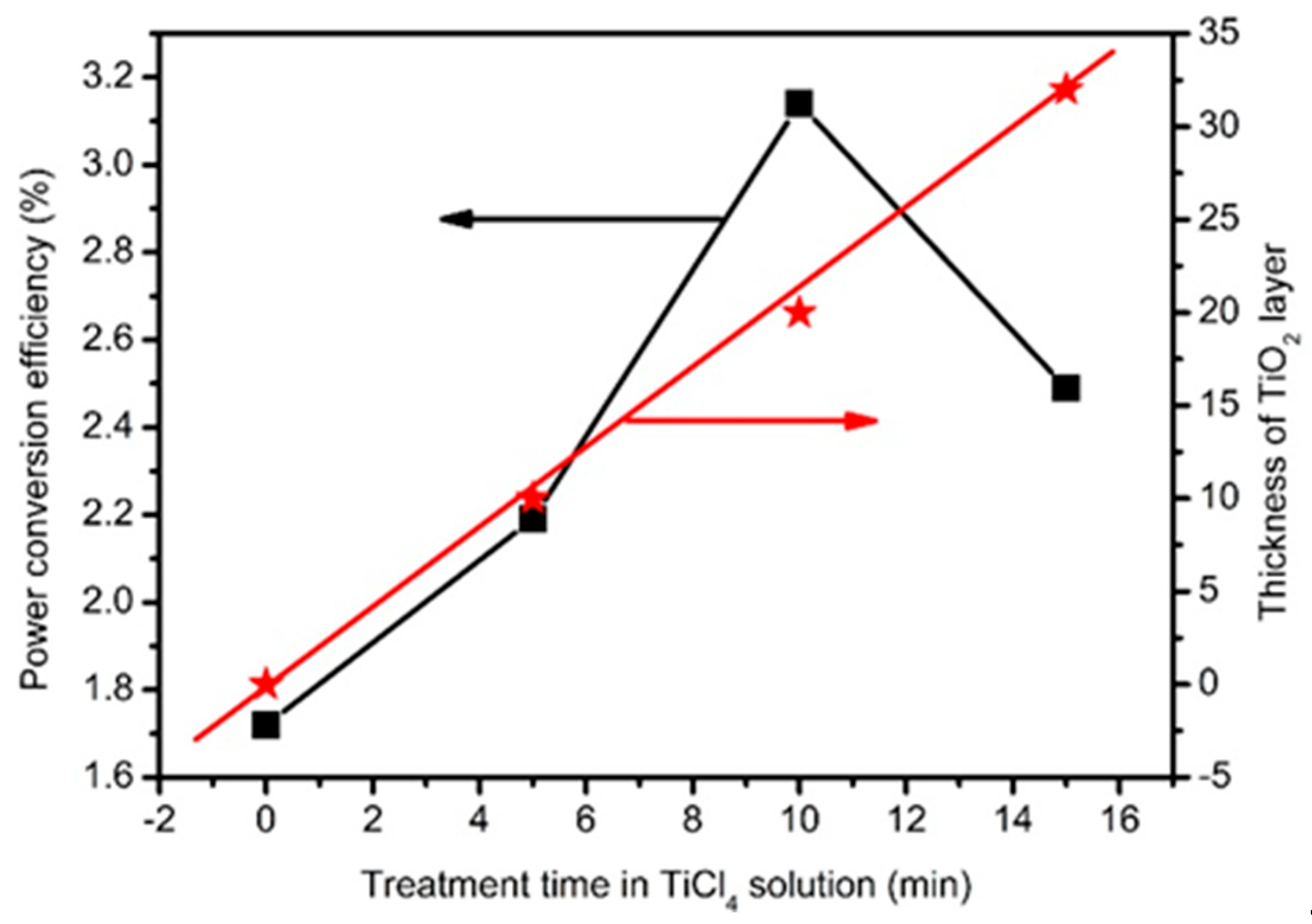
| Solar cells | Voc (V) | Jsc (mA cm−2) | FF | PCE (%) |
|---|---|---|---|---|
| Blank | 0.39 (0.40) | 8.75 (8.79) | 0.43 (0.44) | 1.49 ± 0.05 (1.55) |
| 5-min | 0.40 (0.41) | 10.44 (10.49) | 0.45 (0.46) | 1.88 ± 0.12 (1.98) |
| 10-min | 0.45 (0.46) | 14.57 (14.64) | 0.46 (0.47) | 2.99 ± 0.48 (3.16) |
| 15-min | 0.44 (0.45) | 12.83 (12.89) | 0.42 (0.43) | 2.41 ± 0.10 (2.49) |
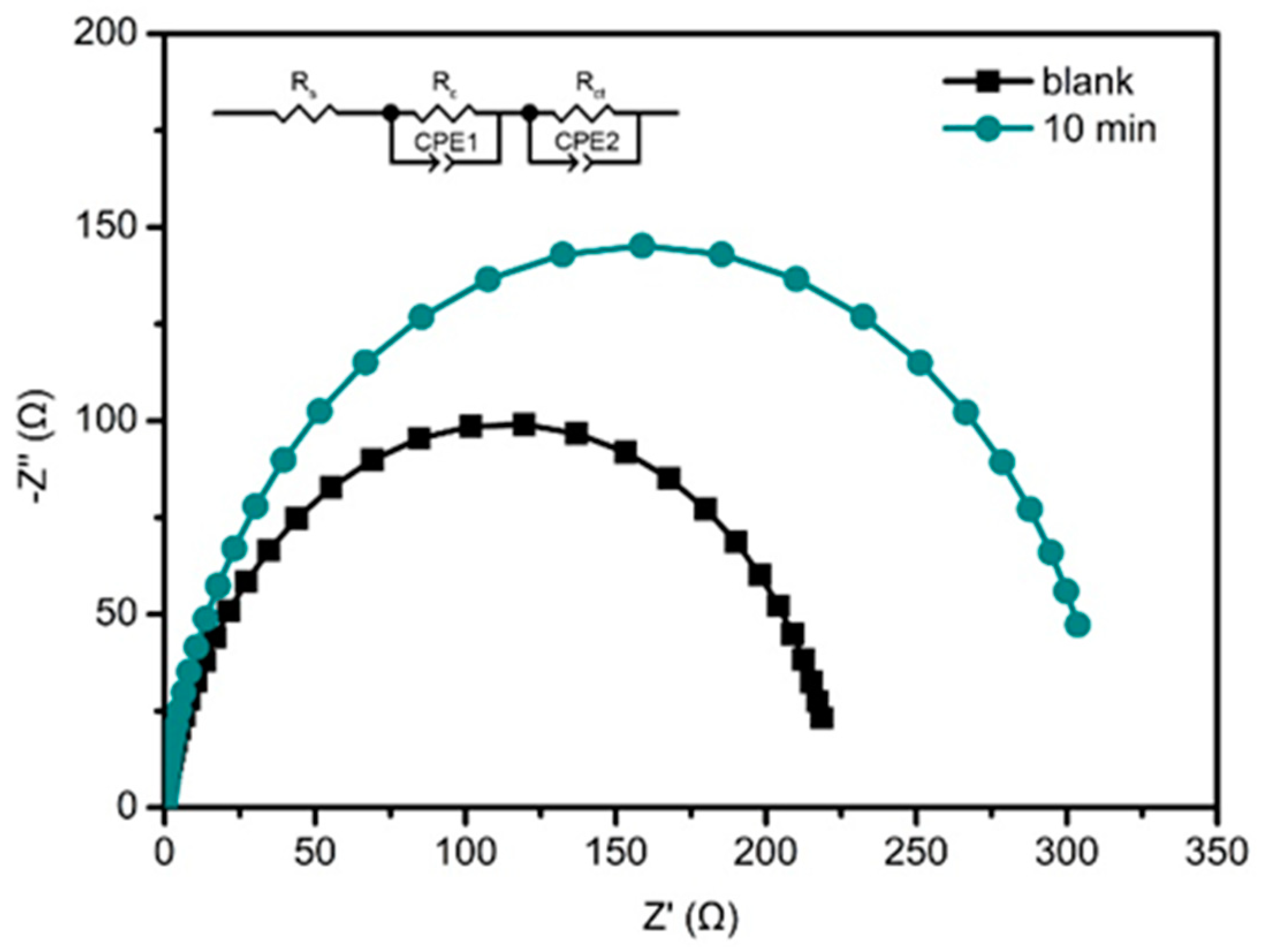
| Photoanodes | Rc (Ω) | Rct (Ω) | Cμ (μF) | τn (ms) |
|---|---|---|---|---|
| ZnO HMS | 5.1 | 218 | 948 | 207 |
| TiO2@ZnO HMS | 4.8 | 309 | 945 | 292 |
© 2020 by the authors. Licensee MDPI, Basel, Switzerland. This article is an open access article distributed under the terms and conditions of the Creative Commons Attribution (CC BY) license (http://creativecommons.org/licenses/by/4.0/).
Share and Cite
Li, Z.; Yu, L.; Wang, H.; Yang, H.; Ma, H. TiO2 Passivation Layer on ZnO Hollow Microspheres for Quantum Dots Sensitized Solar Cells with Improved Light Harvesting and Electron Collection. Nanomaterials 2020, 10, 631. https://doi.org/10.3390/nano10040631
Li Z, Yu L, Wang H, Yang H, Ma H. TiO2 Passivation Layer on ZnO Hollow Microspheres for Quantum Dots Sensitized Solar Cells with Improved Light Harvesting and Electron Collection. Nanomaterials. 2020; 10(4):631. https://doi.org/10.3390/nano10040631
Chicago/Turabian StyleLi, Zhen, Libo Yu, Hao Wang, Huiwen Yang, and Huan Ma. 2020. "TiO2 Passivation Layer on ZnO Hollow Microspheres for Quantum Dots Sensitized Solar Cells with Improved Light Harvesting and Electron Collection" Nanomaterials 10, no. 4: 631. https://doi.org/10.3390/nano10040631
APA StyleLi, Z., Yu, L., Wang, H., Yang, H., & Ma, H. (2020). TiO2 Passivation Layer on ZnO Hollow Microspheres for Quantum Dots Sensitized Solar Cells with Improved Light Harvesting and Electron Collection. Nanomaterials, 10(4), 631. https://doi.org/10.3390/nano10040631