Abstract
Patients who require dental prosthetic restoration using frame dentures in the front part of the mouth very frequently report that teeth fall out of their dentures. However, the available scientific papers are insufficient to compare the various methods of improving the connection between the denture base and the artificial tooth and choosing the best solution. This paper focuses on providing all parameters, enabling the reproduction of tests, and accounting for all variables. The paper uses an original method of creating grooves, sandpaper, sandblasting, and cutting the acrylate layer with a burr in one and two directions. Developed surfaces were additionally subjected to detailed examination. This study used 180 specimens divided into three groups and subjected to various environments (dry, artificial saliva, and thermocycles). Shearing and tensile strength tests were performed. The best results were obtained with a carbide burr. The increase in connection durability was as follows in the case of the shear test: 116.47% in dry samples, 155.38% in samples soaked in artificial saliva, and 46.59% in samples after thermocycles. The increase in tensile resistance was: 198.96% in a dry environment, 88.10% before being soaked in artificial saliva, and 94.04% after thermocycles.
1. Introduction
Dental acrylic resin is the primary material used in dental technology [1,2,3]. It is used to create removable braces, obturators, and complete or partial dentures. Acrylic resin includes mainly polymethyl methacrylate (PMMA) with additives that provide the material’s required hardness, color, or extended life [4].
Dentures consist of prefabricated artificial teeth and, in the case of complete dentures, a dental base plate. Where treatment requires a removable denture, there are additional metal components such as clasps and (in the case of removable denture metal frameworks) a palate arch or plate [5]. The presented research focused mainly on analyzing the connection between teeth and the dental base plate; therefore, only these elements will be further taken into account in this paper.
Three types of artificial teeth are available: ceramic, composite, and acrylic. Acrylic teeth are the most popular, as they are cheaper than the others and form the best connection with the acrylic base plate [4]. The dental base is also made of PMMA. Both materials differ in terms of other substances, such as coloring agents [6], but the primary material is the same. Artificial teeth are made of acrylic that has already been polymerized during the production stage. A dental technician creates an acrylic base plate by mixing liquid monomer and powder polymer.
The connection between the polymerized teeth and the polymerizing acrylic base plate is chemical [1,2,4,7,8]. Dental technicians use various procedures to improve it:
- Procedures enabling the creation of new chains and/or increasing the over-etching of the tooth’s structure (e.g., through using isobutyl methacrylate [9], dichloromethane [10], MMA [9,11], etc.), ready-made mixes sold as “glues” [9,12,13,14,15]), or rubbing the tooth structure with a selected chemical reagent;
- Mechanical modification of the surface, wherein technicians create retainers [16,17,18,19] or develop the surface [9,14,19,20,21,22,23,24];
- A combination of the two above methods (which is even suggested by manufacturers [15]).
However, multiple factors affect the quality of connections between the above elements. The above modifications of tooth surfaces give satisfying results provided that the following conditions are met [4,16,17]:
- The patient is missing two or more teeth;
- The force exerted on the tooth acts along the axis of the tooth (such forces are present in the case of premolars and molars);
- The surface of contact between the artificial tooth and the dental base is quite large (again, such surfaces are present in the case of premolars and molars);
- The teeth can be more deeply embedded into the dental plate (possibly in complete acrylic dentures).
In these conditions, the force is distributed across the tooth surface regularly enough to reduce the probability of a tooth being knocked out to a minimum. A problem appears when conditions significantly increasing the likelihood of a tooth coming loose are present. These include a thin layer of acrylic directly underneath the tooth, a small area of contact between the tooth and the dental plate, and the effects of forces acting at an angle to the tooth axis. These difficulties must be dealt with during the prosthetic restoration of individual missing teeth in the front part of the mouth using a denture framework [5].
Denture frameworks are much more expensive than complete acrylic dentures. Therefore, despite the higher price, patients receive a product that is much more susceptible to damage. The literature indicates that the problem is quite common; as many as 33% of denture repairs result from teeth being knocked out from dentures, with 29% of these incidents involving front teeth [20,25]. As a result, dentures that should serve their users for several years require repair after only a few months.
Another problem in this area is the difficulty in comparing experimental data. Numerous studies have analyzed the impact of acrylic tooth surface modifications on the quality of their connection with the acrylic denture base. Unfortunately, researchers do not use a single research model, and standards have been modified numerous times or do not reflect the actual situation and forces present in the mouth. The authors of the presented paper intended to organize the knowledge available in this area, enable a comparison of results, and specify the exact parameters of the best possible surface modification.
Therefore, this paper aims to analyze various mechanical surface development methods and their impact on the connection between polymerized acrylic and acrylic in the course of polymerization. The authors intended to determine the specific surface modification (its parameters, shape, etc.) that significantly impacts the strength of the connection between the materials. We decided to disregard the impact of chemical modification at this stage, as only a detailed analysis of individual modifications may answer the question of which method gives the best results.
The article also discussed the influence of the environment of the oral cavity on the quality of the connection.
2. Materials and Methods
Work began with creating forms using a 3D printer to prepare samples of suitable shapes for shear and tensile strength testing. The two tests were chosen to be incisors subjected to a shearing force, which knocks the teeth out, and a tensile force, which contributes to the tooth becoming unstuck from the base [4,17]. Samples and tests followed the standard application of dental materials used in dental prostheses (ISO 22112:2017). The material imitating artificial teeth was made of commercial Vertex Rapid Simplified heat-cured acrylic resin (Vertex Dental, Soesterberg, The Netherlands). The material imitating the dental base was an original acrylic composite reinforced with cellulose fibers, described in detail in the article [26]. Various fillers may be used to reinforce PMMA, primarily made up of dental acrylic resin [27,28,29,30,31]. However, due to its lack of impact on the color of prostheses, biocompatibility, and the low market price of cellulose compared to other fillers, our original composite best meets the requirements expected from materials used in dental plates. In addition, the material is more durable than standard acrylic [32] and was devised as an element of a larger research project (of which this paper is a part).
The test samples were made up of two parts (Figure 1). The part imitating an acrylic tooth was the first to be created (Figure 2). The next stage was the modification of its surface using selected methods of mechanical surface development. As a result, the sample was consistent with a tooth in the preparation stage before the polymerization process. All prepared surfaces were also subjected to microgeometry testing with the contact profilometry method using a type S neox 3D Sensofar optical profilometer manufactured by Terrassa (Barcelona, Spain) and energy-dispersive X-ray spectroscopy (EDS) using a JSM-6610LV Scanning Electron Microscope (SEM) manufactured by JEOL (Peabody, MA, USA). Before preparing the second part of the sample, all surfaces were cleaned with a jet of warm water and dried (to prevent any dirt on the surface). The samples were not treated with any other chemical reagents. The samples prepared this way were again placed in the previously printed molds and finished using acrylic composite to obtain a complete sample.
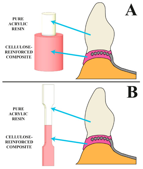
Figure 1.
The visualization shows the samples’ shapes and corresponding components of a dental framework. Samples used in (A) shear testing, (B) tensile testing.

Figure 2.
Location subjected to surface development shown on: (A) a photograph showing the prepared halves imitating a tooth, (B) a visualization showing the connection with the component imitating a dental base (figure from in the Ph.D. thesis: The influence of cellulose on the properties of methacrylic polymers for dental applications, J. Taczała-Warga).
All samples were created and processed by a single person to avoid the impact of human error on the tests.
The research included all examined surface modifications based on surface development so far:
- Cutting a layer of glazing using a burr [9,20,21,22,23] (group CB_III and CB_#);
- Sandblasting [9,11,14,19,20,21,22,23,24,33,34,35,36] (group SB);
- Using sandpaper [37,38,39,40] (group SP).
Retainers were not included in the study as their size prevents an objective comparison with the surface development method. Furthermore, they have already been analyzed by authors of papers [16,17] and do not affect connection quality.
The above surface development methods were compared with our original modification method—grooving (group G)—and control samples without surface modification. Rifling parameters were chosen based on experimentally tested numerical simulations described in detail in the literature [41]. A prosthetic diamond disc with a thickness of 0.20 mm was used to create the grooves. Finally, two grooves were created at a distance of 5.00 mm.
Table 1 shows all parameters of surface modification. The parameters used were set based on the above references.

Table 1.
Applied surface modifications and their parameters.
All samples were additionally divided into three groups based on the impact of the oral environment:
- No impact (group D);
- After thermocycles [14,21,42,43,44,45] (group T);
- After soaking in artificial saliva [9,21,44,45,46,47] (group AF).
A total of 180 samples were prepared. The entire division and marking of samples are shown in Table 2.

Table 2.
Legend for marking and dividing samples.
Thermocycles were carried out using a Thermocykler THE1100e device, manufactured by SD Mechatronik GmbH (Feldkirchen-Westerham, Germany), using the following settings: 5000 cycles, a temperature between 5 °C and 55 °C, drying time 10 s. The settings used were chosen and averaged based on research covering similar issues [14,21,42,43,44,45].
Artificial saliva was prepared based on a mixture described by Fusayama–Meyer [48,49,50,51,52]. Its composition and proportions are shown in Table 3. The ingredients were diluted in distilled water. All reagents were manufactured by Chempur (Piekary Śląskie, Poland). The samples created were soaked for 48 h at 37 °C before testing [9,38,47].

Table 3.
Composition of the artificial saliva.
Strength (shear and tensile) tests were performed using a universal testing machine (Zwick/Roell) following standards used in dentistry and dental technology (ISO 22112:2017). The machine knife displacement rate was set to 2 mm/min. The results were statistically analyzed using Origin 2020 statistical software (OriginLab Corporation, Northampton, MA, USA). The individual research hypotheses were tested using the 2-way ANOVA test, with statistical significance assumed at a level of p = 0.05, and the HSD Tukey’s post hoc test was applied in statistical analyses. The direction of the force is shown in Figure 3.
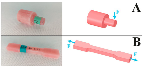
Figure 3.
Diagram of the direction of force during strength testing: (A) shear test, (B) tensile test. Photographs on the left show the appearance of the final samples.
Following the strength tests, fissures in all samples were analyzed using a VHX confocal microscope manufactured by Keyence International (Mechelen, Belgium).
3. Results
3.1. 3D Microscope Observations by Profilometer
All measurements were made on the same surface area (1.57 × 1.32 mm). The test produced colorful maps of sample surfaces (Figure 4) and 2D charts of the average arithmetic deviation of the roughness profile (i.e., the Ra parameter (Figure 5)), calculated following standard ISO 4287. Ra values were compared to measured values of the following 3D parameters: average arithmetic deviation of the height of surface unevenness from the reference plane (Sa) and average square deviation of the surface unevenness from the reference plane (Sq), determined following standard ISO 25178. The obtained values enabled a detailed assessment of the micro geometry created on the surface of the samples [53,54].
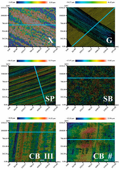
Figure 4.
Deformation maps for all surface preparation methods were obtained using a 3D profilometer. The blue line marks the sections used to measure the Ra parameter (figure from the Ph.D. thesis: The influence of cellulose on the properties of methacrylic polymers for dental applications, J. Taczała-Warga).
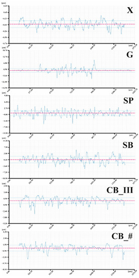
Figure 5.
Chart of Ra roughness measured along the blue lines marked in Figure 4 (figure from the Ph.D. thesis: The influence of cellulose on the properties of methacrylic polymers for dental applications, J. Taczała-Warga).
Sa and Sq values for all tested groups was as follows:
- X—Sa 0.26 μm, Sq 0.33 μm;
- G—Sa 42.84 μm, Sq 45.39 μm;
- SP—Sa 2.17 μm, Sq 2.72 μm;
- SB—Sa 2.86 μm, Sq 3.60 μm;
- CB_III—Sa 0.79 μm, Sq 1.04 μm;
- CB_#—Sa 1.54 μm, Sq 1.99 μm.
The results of the Ra parameter are shown in Figure 6. The following average values were recorded: for X group 0.11 μm, for G group 0.99 μm, for SP 1.51 μm, for CB_III 0.53 μm, and for CB_# 0.83 μm.
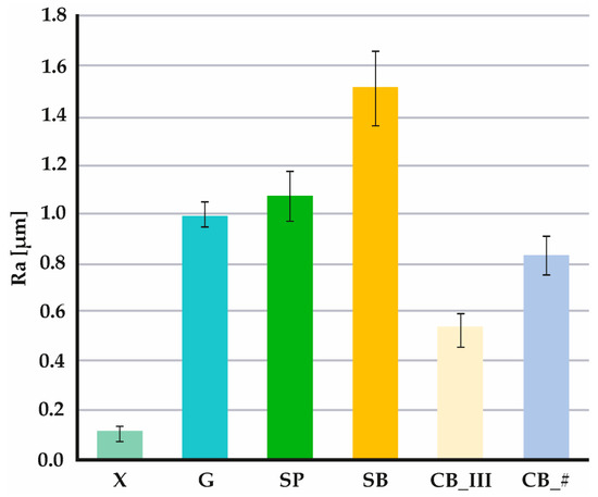
Figure 6.
Values of the Ra parameter for each surface development method (figure from the Ph.D. thesis: The influence of cellulose on the properties of methacrylic polymers for dental applications, J. Taczała-Warga).
3.2. EDS
Examination under SEM and EDS analyses (Figure 7 and Figure 8) were carried out to characterize all mechanical preparations of sample surfaces better. Measurements were performed at the following device settings: 20 kV, 30 Pa, magnification ×100 in the case of SEM, and ×500 in the case of EDS.
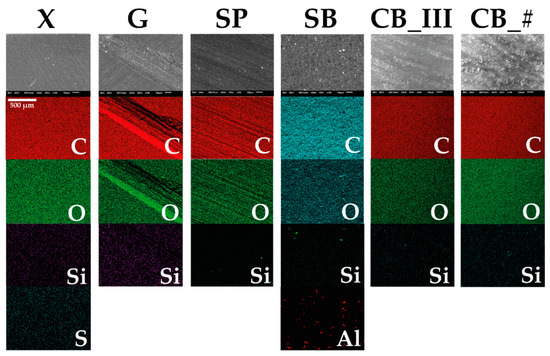
Figure 7.
EDS analyses obtained and corresponding SEM images (figure from the Ph.D. thesis: The influence of cellulose on the properties of methacrylic polymers for dental applications, J. Taczała-Warga).
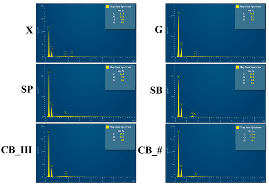
Figure 8.
Measurements of spectrums of each element from the EDS analysis (figure from the Ph.D. thesis: The influence of cellulose on the properties of methacrylic polymers for dental applications, J. Taczała-Warga).
3.3. Strength Tests
Two strength tests were performed to obtain results mirroring, as closely as possible, the natural conditions in the mouth and outside. The samples were subjected to shearing and tensile force. The results are presented in graphical form in Figure 9.

Figure 9.
Shear and tensile test results (figure from the Ph.D. thesis: The influence of cellulose on the properties of methacrylic polymers for dental applications, J. Taczała-Warga).
Detailed results of both tests are also presented in tabular format (Table 4).

Table 4.
Results of the shear test of the connection.
The performed statistical analysis of the variance of the results (2-way ANOVA) of the shear and tensile strength tests showed statistically significant differences between the mean (i.e., mean shear and tensile strengths) in the groups of samples prepared with different methods (p < 0.05). At the same time, the results of the F test with the adopted level of significance (p = 0.05) indicate no grounds to reject the hypothesis that there are no differences between averages (i.e., average shear and tensile strengths) in the groups subjected to conditions in different environments. This means that the type of environment (AF—saliva, T—thermal shocks) has no significant effect on the properties of the tested elements. The analysis of variance with the adopted significance level (p = 0.05) also did not reveal any interaction between the type of sample preparation (method) and the type of environment in which it was then present. Tukey’s post-hoc test of the shear strength test results (Table A1) showed statistically significant differences between the means subjected to different treatments (groups G, SP, SB, CB_III, CB_ #) and the reference group (group X—samples untreated). This means that each type of treatment tested significantly improved the tensile strength of the samples compared to the reference group. In the case of tensile strength (Table A2), the most significant differences were observed for the treated CB_ # vs. the untreated samples (group X).
3.4. Observation of Fissures
All types of damage observed with the microscope are shown in Figure 10.
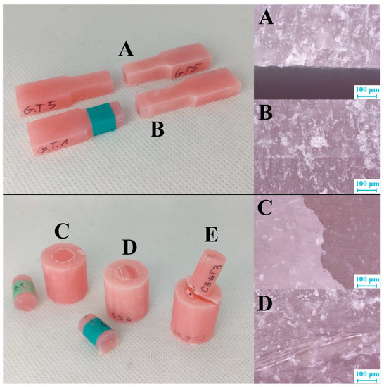
Figure 10.
Representations of all types of cracks observed during the test. Photos of the samples are on the left, and photos of fissures made using a confocal microscope are on the right. Tensile test: (A) crack at the connection; (B) crack deep inside the material. Shear test: (C) crack at the connection in X group samples; (D) crack deep in the material; (E) no complete breakage (figure from the Ph.D. thesis: The influence of cellulose on the properties of methacrylic polymers for dental applications, J. Taczała-Warga).
4. Discussion
By analyzing the obtained data, we can confirm that a smooth sample surface subjected to no mechanical processing (control sample marked as X) has the lowest Ra roughness coefficient. The tested value of this parameter in the sample was 0.11 μm. The same sample also had the lowest Sa (0.26 μm) and Sq (0.33 μm) parameters. The literature data also confirm that the test was performed correctly, as the measured Ra roughness parameter for an entire acrylic surface was 0.12 μm [55].
The average Ra coefficient for a grooved sample (G) is 0.99 μm. However, given the information shown in Figure 4 and Figure 5 and the results of the Sa (42.84 μm) and Sq (45.39 μm) measurements, it is apparent that the roughness value in the groove itself is much higher than on an untreated surface. Roughness inside the groove ranges from approximately 8.00 μm to approx. 9.00 μm on the chart, with the entire groove forming a straightforward step. This range of values was measured at a depth below the untreated surface of the sample.
The parameters measured on the surface of the sample treated with sandpaper (SP) of Ra 1.07 μm were also nearly identical to results found in the literature, with the Ra coefficient measured at 1.03 μm [56].
The highest Ra coefficient was recorded in sandblasted samples (SB) = 1.51 μm, Sa 2.86 μm, and Sq 3.60 μm. Up to this point, an upwards trend of the Ra coefficient had been recorded. Samples prepared using a prosthetic carbide burr had lower Ra coefficients. Cutting the resin layer in one direction (CB_III) resulted in a Ra value of 0.53 μm, and in two directions (CB_#) produced a Ra value of 0.83 μm. Of note, however, is that in the case of these two methods, peaks with extreme negative values were predominant (positive values are not that extreme). The results differ from those presented by other researchers (Ra 1.52 μm in reference [56]). However, the materials and techniques used play a vital role when comparing sanding and burring. Many papers do not provide information on the angle used when sandblasting, while research shows that this aspect is essential in the context of connecting materials [34,35]. The situation is similar concerning the choice of burrs. In their articles, researchers only specify that the external layer was cut using a cemented carbide burr. However, burrs are available in numerous shapes, with slots made using various methods and in various thicknesses, and may also be made of multiple alloys or coated with additional material [57]. In our paper, we provide all parameters to enable researchers to reproduce and compare the tests and to allow dental technicians to choose precisely the same method as the one used by us to achieve their intended goal, namely improving the quality of connection. As a result, parameters provided by other researchers are insufficient to compare results reliably.
An analysis of surfaces prepared using the EDS method confirmed that the main elements, carbon (C) and oxygen (O), were abundant in all samples. These are the essential elements found in polymethyl methacrylate. In addition, silicon (Si) was found in all groups. Silicon is one of the elements often found among ingredients of commercial acrylic resin [58]. Silica is used as a filler.
Other elements detected in various samples include sulfur (S) in the control sample marked as X and aluminum (Al) in sample SB. As S is another element present in fillers [59], we can assume that a significant amount of sulfur is deposited outside the material during polymerization and mechanical treatment causes this layer to be destroyed. Another possibility is that S is present in all samples, but only in the case of the X group sample was the amount of sulfur in the examined area sufficient to be detected. Al was another identified element. As Al was found in the sandblasted sample marked as SB, and Al2O3 was the material used for sandblasting, we can conclude that this treatment method causes sand particles to become embedded in the material. This may create something like hooks filled with acrylic from the denture base (in this case, composite from the second part of the sample).
As the SP sample did not contain a more significant amount of Si than the other samples, we can assume that fragments of sandpaper did not become embedded during treatment, as the material used in the testing was made of SiC.
As predicted, both tests of the X control samples yielded the lowest results. This shows how important it is to correctly prepare the tooth’s surface before connecting it with acrylic. Regarding the impact of the environment, artificial saliva reduced the shear strength of the X samples but increased their tensile strength. The opposite was observed about the effect of thermocycles.
Considering all of the results, the following upward trend was observed: G, SP, SB, CB_III, CB_#. The highest values in tensile and shear tests were measured in samples treated using a cemented carbide burr. The highest strength jump occurs in tensile tests after subjecting the samples to thermocycles. To avoid this jump, the patient can be told to avoid eating very hot/cold food or to take extended breaks between consuming these foods or beverages. The percentage increase of durability of connections made using this method compared to control samples is as follows in the case of shear resistance: increase by 116.47% in dry samples, 155.38% in samples soaked in artificial saliva, and 46.59% in samples subjected to thermocycles. The increase of tensile resistance in the samples was as follows: 198.96% in dry samples, 88.10% in samples soaked in artificial saliva, and 94.04% in samples subjected to thermocycles.
It would seem that the high roughness coefficient of the SB samples should positively impact the quality of the connection. However, the results of the test indicate otherwise. There may be two reasons for this. The first is that excessive differences in surface heights may increase the material’s susceptibility to cracking, and the second is the presence of aluminum oxide particles embedded in the sample’s surface. The hooks created this way do not improve the adhesion of the acrylic and may cause air bubbles to appear. This, as well as the presence of a material other than acrylic, may reduce the area of connection between the acrylic and the second part of the sample.
The last stage of the test was the observation of fissures under a microscope. The examination did not indicate any significant impact of the surface preparation on the manner of cracking. The only correlation was the smooth cracks at the connection of both materials in all X samples. Mechanical modification of the samples caused cracks to appear deep inside the pure acrylic or acrylic composite.
The presence of cracks deep in the material means that the durability of the connection was more significant than the material’s durability. Furthermore, it is worth noting that no samples were destroyed (apart from samples from the X group). This means that any mechanical modification increases the strength of the connection between the materials and may contribute to the gradual propagation of cracks [41]. The appearance of a crack will, therefore, not prevent the patient from continuing to use the denture until a tooth is entirely knocked out.
5. Conclusions
In conclusion, we may clearly state that any mechanical modification significantly impacts the connection between a dental base and an artificial tooth.
To further improve the quality of connection where increased durability is required, dental technicians should prepare dentures using a cemented carbide burr. This method will significantly improve the quality of the connection. To further extend the life of such a connection, the patient should avoid eating very hot/cold food or take long breaks between consuming these foods or liquids.
We note that in the study presented above, we focused solely on mechanical methods of surface development to ensure that our research of this method is as thorough as possible and other available research can be systematized. Future researchers and dental technicians now possess precise data enabling them to compare methods and use them in their laboratories.
Combining this technique with chemical surface modification may allow us to obtain even better properties and will be the subject of our future research.
Author Contributions
Conceptualization, J.T.-W. and J.S. (Jacek Sawicki); methodology, J.T.-W., J.S. (Jacek Sawicki), and M.K.; formal analysis, J.S. (Jacek Sawicki); investigation, J.T.-W. and M.K.; writing—original draft preparation, J.T.-W.; writing—review and editing, J.S. (Jacek Sawicki) and J.S. (Jerzy Sokołowski); supervision, J.S. (Jacek Sawicki) and J.S. (Jerzy Sokołowski). All authors have read and agreed to the published version of the manuscript.
Funding
This research received no external funding.
Institutional Review Board Statement
Not applicable.
Informed Consent Statement
Not applicable.
Conflicts of Interest
The authors declare no conflict of interest.
Appendix A
Results of performed HSD Tukey’s statistical tests are shown below, with the shear test in Table A1 and the tensile test in Table A2.

Table A1.
HSD Tukey’s test; variable shear stress. Approximate probabilities for post hoc tests.
Table A1.
HSD Tukey’s test; variable shear stress. Approximate probabilities for post hoc tests.
| Surface Preparation | Environment | 1 | 2 | 3 | 4 | 5 | 6 | 7 | 8 | 9 | 10 | 11 | 12 | 13 | 14 | 15 | 16 | 17 | 18 | |
| 1 | X | D | 1.00 | 0.64 | 0.95 | 0.01 | 0.20 | 0.04 | 0.71 | 0.60 | 0.01 | 0.01 | 0.00 | 0.03 | 0.20 | 0.03 | 0.00 | 0.00 | 0.00 | |
| 2 | X | AF | 1.00 | 0.26 | 0.66 | 0.00 | 0.05 | 0.01 | 0.31 | 0.23 | 0.00 | 0.00 | 0.00 | 0.00 | 0.05 | 0.01 | 0.00 | 0.00 | 0.00 | |
| 3 | X | T | 0.64 | 0.26 | 1.00 | 0.87 | 1.00 | 1.00 | 1.00 | 1.00 | 0.94 | 0.91 | 0.79 | 0.99 | 1.00 | 0.99 | 0.17 | 0.01 | 0.05 | |
| 4 | G | D | 0.95 | 0.66 | 1.00 | 0.49 | 1.00 | 0.88 | 1.00 | 1.00 | 0.63 | 0.55 | 0.38 | 0.81 | 1.00 | 0.85 | 0.04 | 0.00 | 0.01 | |
| 5 | G | AF | 0.01 | 0.00 | 0.87 | 0.49 | 1.00 | 1.00 | 0.83 | 0.90 | 1.00 | 1.00 | 1.00 | 1.00 | 1.00 | 1.00 | 1.00 | 0.73 | 0.97 | |
| 6 | G | T | 0.20 | 0.05 | 1.00 | 1.00 | 1.00 | 1.00 | 1.00 | 1.00 | 1.00 | 1.00 | 0.99 | 1.00 | 1.00 | 1.00 | 0.60 | 0.07 | 0.28 | |
| 7 | SP | D | 0.04 | 0.01 | 1.00 | 0.88 | 1.00 | 1.00 | 0.99 | 1.00 | 1.00 | 1.00 | 1.00 | 1.00 | 1.00 | 1.00 | 0.94 | 0.32 | 0.71 | |
| 8 | SP | AF | 0.71 | 0.31 | 1.00 | 1.00 | 0.83 | 1.00 | 0.99 | 1.00 | 0.91 | 0.87 | 0.74 | 0.98 | 1.00 | 0.99 | 0.14 | 0.01 | 0.04 | |
| 9 | SP | T | 0.60 | 0.23 | 1.00 | 1.00 | 0.90 | 1.00 | 1.00 | 1.00 | 0.96 | 0.93 | 0.83 | 0.99 | 1.00 | 1.00 | 0.20 | 0.01 | 0.06 | |
| 10 | SB | D | 0.01 | 0.00 | 0.94 | 0.63 | 1.00 | 1.00 | 1.00 | 0.91 | 0.96 | 1.00 | 1.00 | 1.00 | 1.00 | 1.00 | 1.00 | 0.60 | 0.93 | |
| 11 | SB | AF | 0.01 | 0.00 | 0.91 | 0.55 | 1.00 | 1.00 | 1.00 | 0.87 | 0.93 | 1.00 | 1.00 | 1.00 | 1.00 | 1.00 | 1.00 | 0.68 | 0.96 | |
| 12 | SB | T | 0.00 | 0.00 | 0.79 | 0.38 | 1.00 | 0.99 | 1.00 | 0.74 | 0.83 | 1.00 | 1.00 | 1.00 | 0.99 | 1.00 | 1.00 | 0.83 | 0.99 | |
| 13 | CB_III | D | 0.03 | 0.00 | 0.99 | 0.81 | 1.00 | 1.00 | 1.00 | 0.98 | 0.99 | 1.00 | 1.00 | 1.00 | 1.00 | 1.00 | 0.97 | 0.41 | 0.80 | |
| 14 | CB_III | AF | 0.20 | 0.05 | 1.00 | 1.00 | 1.00 | 1.00 | 1.00 | 1.00 | 1.00 | 1.00 | 1.00 | 0.99 | 1.00 | 1.00 | 0.60 | 0.07 | 0.28 | |
| 15 | CB_III | T | 0.03 | 0.01 | 0.99 | 0.85 | 1.00 | 1.00 | 1.00 | 0.99 | 1.00 | 1.00 | 1.00 | 1.00 | 1.00 | 1.00 | 0.96 | 0.36 | 0.76 | |
| 16 | CB_# | D | 0.00 | 0.00 | 0.17 | 0.04 | 1.00 | 0.60 | 0.94 | 0.14 | 0.20 | 1.00 | 1.00 | 1.00 | 0.97 | 0.60 | 0.96 | 1.00 | 1.00 | |
| 17 | CB_# | AF | 0.00 | 0.00 | 0.01 | 0.00 | 0.73 | 0.07 | 0.32 | 0.01 | 0.01 | 0.60 | 0.68 | 0.83 | 0.41 | 0.07 | 0.36 | 1.00 | 1.00 | |
| 18 | CB_# | T | 0.00 | 0.00 | 0.05 | 0.01 | 0.97 | 0.28 | 0.71 | 0.04 | 0.06 | 0.93 | 0.96 | 0.99 | 0.80 | 0.28 | 0.76 | 1.00 | 1.00 |

Table A2.
HSD Tukey’s test; variable tensile stress. Approximate probabilities for post hoc tests.
Table A2.
HSD Tukey’s test; variable tensile stress. Approximate probabilities for post hoc tests.
| Surface Preparation | Environment | 1 | 2 | 3 | 4 | 5 | 6 | 7 | 8 | 9 | 10 | 11 | 12 | 13 | 14 | 15 | 16 | 17 | 18 | |
| 1 | X | D | 1.00 | 1.00 | 1.00 | 0.95 | 1.00 | 1.00 | 0.62 | 0.37 | 0.95 | 0.80 | 0.16 | 0.01 | 0.10 | 0.36 | 0.00 | 0.04 | 0.63 | |
| 2 | X | AF | 1.00 | 1.00 | 1.00 | 1.00 | 1.00 | 1.00 | 1.00 | 0.98 | 1.00 | 1.00 | 0.86 | 0.28 | 0.75 | 0.98 | 0.03 | 0.49 | 1.00 | |
| 3 | X | T | 1.00 | 1.00 | 1.00 | 0.92 | 1.00 | 1.00 | 0.57 | 0.32 | 0.93 | 0.75 | 0.13 | 0.01 | 0.08 | 0.31 | 0.00 | 0.03 | 0.57 | |
| 4 | G | D | 1.00 | 1.00 | 1.00 | 1.00 | 1.00 | 1.00 | 0.95 | 0.79 | 1.00 | 0.99 | 0.51 | 0.08 | 0.38 | 0.79 | 0.00 | 0.18 | 0.95 | |
| 5 | G | AF | 0.95 | 1.00 | 0.92 | 1.00 | 1.00 | 1.00 | 1.00 | 1.00 | 1.00 | 1.00 | 0.99 | 0.67 | 0.98 | 1.00 | 0.13 | 0.87 | 1.00 | |
| 6 | G | T | 1.00 | 1.00 | 1.00 | 1.00 | 1.00 | 1.00 | 1.00 | 0.97 | 1.00 | 1.00 | 0.84 | 0.25 | 0.72 | 0.97 | 0.02 | 0.45 | 1.00 | |
| 7 | SP | D | 1.00 | 1.00 | 1.00 | 1.00 | 1.00 | 1.00 | 1.00 | 0.99 | 1.00 | 1.00 | 0.89 | 0.31 | 0.79 | 0.99 | 0.03 | 0.53 | 1.00 | |
| 8 | SP | AF | 0.62 | 1.00 | 0.57 | 0.95 | 1.00 | 1.00 | 1.00 | 1.00 | 1.00 | 1.00 | 1.00 | 0.96 | 1.00 | 1.00 | 0.44 | 1.00 | 1.00 | |
| 9 | SP | T | 0.37 | 0.98 | 0.32 | 0.79 | 1.00 | 0.97 | 0.99 | 1.00 | 1.00 | 1.00 | 1.00 | 1.00 | 1.00 | 1.00 | 0.71 | 1.00 | 1.00 | |
| 10 | SB | D | 0.95 | 1.00 | 0.93 | 1.00 | 1.00 | 1.00 | 1.00 | 1.00 | 1.00 | 1.00 | 0.99 | 0.65 | 0.97 | 1.00 | 0.12 | 0.85 | 1.00 | |
| 11 | SB | AF | 0.80 | 1.00 | 0.75 | 0.99 | 1.00 | 1.00 | 1.00 | 1.00 | 1.00 | 1.00 | 1.00 | 0.88 | 1.00 | 1.00 | 0.28 | 0.97 | 1.00 | |
| 12 | SB | T | 0.16 | 0.86 | 0.13 | 0.51 | 0.99 | 0.84 | 0.89 | 1.00 | 1.00 | 0.99 | 1.00 | 1.00 | 1.00 | 1.00 | 0.92 | 1.00 | 1.00 | |
| 13 | CB_III | D | 0.01 | 0.28 | 0.01 | 0.08 | 0.67 | 0.25 | 0.31 | 0.96 | 1.00 | 0.65 | 0.88 | 1.00 | 1.00 | 1.00 | 1.00 | 1.00 | 0.96 | |
| 14 | CB_III | AF | 0.10 | 0.75 | 0.08 | 0.38 | 0.98 | 0.72 | 0.79 | 1.00 | 1.00 | 0.97 | 1.00 | 1.00 | 1.00 | 1.00 | 0.97 | 1.00 | 1.00 | |
| 15 | CB_III | T | 0.36 | 0.98 | 0.31 | 0.79 | 1.00 | 0.97 | 0.99 | 1.00 | 1.00 | 1.00 | 1.00 | 1.00 | 1.00 | 1.00 | 0.71 | 1.00 | 1.00 | |
| 16 | CB_# | D | 0.00 | 0.03 | 0.00 | 0.00 | 0.13 | 0.02 | 0.03 | 0.44 | 0.71 | 0.12 | 0.28 | 0.92 | 1.00 | 0.97 | 0.71 | 1.00 | 0.44 | |
| 17 | CB_# | AF | 0.04 | 0.49 | 0.03 | 0.18 | 0.87 | 0.45 | 0.53 | 1.00 | 1.00 | 0.85 | 0.97 | 1.00 | 1.00 | 1.00 | 1.00 | 1.00 | 1.00 | |
| 18 | CB_# | T | 0.63 | 1.00 | 0.57 | 0.95 | 1.00 | 1.00 | 1.00 | 1.00 | 1.00 | 1.00 | 1.00 | 1.00 | 0.96 | 1.00 | 1.00 | 0.44 | 1.00 |
References
- Powers, M.J.; Wataha, C.J. Dental Materials: Properties and Manipulation, 10th ed.; Elsevier Health Sciences: Amsterdam, The Netherlands, 2014. [Google Scholar]
- Raszewski, Z. A New View at Acrylic Materials; Elamed: Łódź, Poland, 2009. [Google Scholar]
- Dejak, B. Compendium of Making Prosthetic Restorations; Med Tour Press International: Otwock, Poland, 2014. [Google Scholar]
- Taczała, J.; Sawicki, J. Bond between single artificial teeth and the base plate in removable denture metal framework. J. Achiev. Mater. Manuf. Eng. 2018, 1, 11–21. [Google Scholar] [CrossRef]
- Carr, A.; David, B. McCracken’s Removable Partial Prosthodontics, 13th ed.; Mosby: Maryland Heights, MO, USA, 2015. [Google Scholar]
- Taczała, J. Influence of the inhibitor on the properties of dental acrylic resin. In The Book of Articles National Scientific Conference “Knowledge—Key to Success, 4th ed.; Promovendi Foundation Publishing: Łódź, Poland, 2020; pp. 120–128. [Google Scholar]
- Raszewski, Z. Mechanical properties of hot curing acrylic resins after reinforced with different kinds of fibers. Int. J. Biomed. Mater. Res. 2013, 1, 9–13. [Google Scholar] [CrossRef]
- Majewski, S.W.; Pryliński, M. Materials and Technologies of Contemporary Dental Prosthetics: A Textbook for Dentistry Students, Doctors and Dental Technicians; Czelej: Lublin, Polonia, 2013. [Google Scholar]
- Akin, H.; Kirmali, O.; Tugut, F.; Coskun, M.E. Effects of different surface treatments on the bond strength of acrylic denture teeth to polymethylmethacrylate denture base material. Photomed. Laser Surg. 2014, 32, 512–516. [Google Scholar] [CrossRef]
- Jain, G.; Palekar, U.; Awinashe, V.; Mishra, S.K.; Kawadkar, A.; Rahangdale, T. The effect of different chemical surface treatments of denture teeth on shear bond strength: A comparative study. J. Clin. Diagn. Res. 2014, 8, 15–19. [Google Scholar] [CrossRef]
- Muñoz, M.; Reales, E.; Prates, L.; Volpato, C. Bond strength assessment between acrylic teeth and acrylic resin repairs: Effect of different surface treatments. Odovtos-Int. J. Dent. Sci. 2016, 18, 109–124. [Google Scholar] [CrossRef][Green Version]
- Choi, J.J.E.; Uy, C.E.; Plaksina, P.; Ramani, R.S.; Ganjigatti, R.; Waddell, J.N. Bond strength of denture teeth to heat-cured, CAD/CAM and 3D printed denture acrylics. J. Prosthodont. 2019, 29, 415–421. [Google Scholar] [CrossRef]
- Akin, H.; Tugut, F.; Guney, U.; Akar, T. Shear bond strength of denture teeth to two chemically different denture base resins after various surface treatments. J. Prosthodont. 2014, 23, 152–156. [Google Scholar] [CrossRef]
- Jayakrishnakumar, S.; Ramakrishnan, H.; Divagar, C.; Mahadevan, V.; Azhagarasan, N. Comparative evaluation of the effect of surface treatments on theshearbond strength between acrylic denture teeth and denture base resin—Three dimensional study. IOSR J. Dent. Med. Sci. 2019, 18, 29–45. [Google Scholar] [CrossRef][Green Version]
- Schütz Dental GmbH, FuturAcryl 2000, RosbacH. Available online: https://www.schuetz-dental.de/media/pdf/60/3a/0f/Product_Catalog_English.pdf (accessed on 9 September 2022).
- Taczała, J. Influence of the groove on stress distribution and deformations in the case of a single incisor in removable partial denture metal framework. In The Book of Articles National Scientific Conference “Zrozumieć Naukę”, 2nd ed.; Promovendi Foundation Publishing: Łódź, Poland, 2018; pp. 238–248. [Google Scholar]
- Taczała, J.; Krupanek, K.; Sawicki, J. Numerical analysis of the influence of surface modification on the bond strength between a single incisal tooth with a removable partial denture metal framework. AIP Conf. Proc. 2019, 2078, 020057. [Google Scholar] [CrossRef]
- Phukela, S.S.; Chintalapudi, S.K.; Sachdeva, H.; Dhall, R.S.; Sharma, N.; Prabhu, A. Comparative evaluation of different mechanical modifications of denture teeth on bond strength between high-impact acrylic resin and denture teeth: An in vitro study. J. Int. Soc. Prev. Community Dent. 2016, 6, 161–166. [Google Scholar] [CrossRef]
- Consani, R.L.; Naoe, H.T.; Mesquita, M.F.; Sinhoreti, A.M.; Mendes, W.B. Effect of ridge-lap surface treatments on the bond of resin teeth to denture base. J. Adhes. Dent. 2011, 13, 287–293. [Google Scholar] [CrossRef] [PubMed]
- Patil, S.B.; Naveen, B.H.; Patil, N.P. Bonding acrylic teeth to acrylic resin denture bases: A review. Gerodontology 2006, 23, 131–139. [Google Scholar] [CrossRef] [PubMed]
- Colebeck, A.C.; Monaco, E.A.; Pusateri, C.R.; Davis, E. Microtensile bond strength of different acrylic teeth to high-impact denture base resins. J. Prosthodont. 2015, 24, 43–51. [Google Scholar] [CrossRef] [PubMed]
- Meloto, C.; Silva-Concílio, L.; Rodrigues-Garciai, R.; Canales, G.; Rizzatti-Barbosa, C. Effect of surface treatments on the bond strength of different resin teeth to complete denture base material. Acta Odontol. Lat. 2013, 26, 37–42. [Google Scholar]
- Chung, K.-H.; Chung, C.Y.; Chan, D.C.N. Effect of pre-processing surface treatments of acrylic teeth on bonding to the denture base. J. Oral Rehabil. 2008, 35, 268–275. [Google Scholar] [CrossRef] [PubMed]
- Saavedra, G.; Neisser, M.P.; Sinhoreti, M.A.C.; Machado, C. Evaluation of bond strength of denture teeth bonded to heat polymerized acrylic resin denture bases. Brazilian J. Oral Sci. 2004, 3, 458–464. [Google Scholar] [CrossRef]
- Darbar, U.R.; Huggett, R.; Harrison, A. Denture fracture: A survey. Br. Dent. J. 1994, 176, 342–345. [Google Scholar] [CrossRef] [PubMed]
- Taczała, J.; Sawicki, J.; Pietrasik, J. Chemical modification of cellulose microfibres to reinforce poly(methyl methacrylate) used for dental application. Materials 2020, 13, 3807. [Google Scholar] [CrossRef]
- Alzarrug, F.A.; Dimitrijević, M.M.; Heinemann, R.M.J.; Radojević, V.; Stojanović, D.B.; Uskoković, P.S.; Aleksić, R. The use of different alumina fillers for improvement of the mechanical properties of hybrid PMMA composites. Mater. Des. 2015, 86, 575–581. [Google Scholar] [CrossRef]
- Gad, M.M.; Fouda, S.M.; Al-Harbi, F.A.; Näpänkangas, R.; Raustia, A. PMMA denture base material enhancement: A review of fiber, filler, and nanofiller addition. Int. J. Nanomed. 2017, 12, 3801–3812. [Google Scholar] [CrossRef] [PubMed]
- Marin, E.; Boschetto, F.; Zanocco, M.; Honma, T.; Zhu, W.; Pezzotti, G. Explorative study on the antibacterial effects of 3D-printed PMMA/nitrides composites. Mater. Des. 2021, 206, 109788. [Google Scholar] [CrossRef]
- Chladek, G.; Żmudzki, J.; Basa, K.; Pater, A.; Krawczyk, C.; Pakieła, W. Effect of silica filler on properties of PMMA resin. Arch. Mater. Sci. Eng. 2015, 71, 63–72. [Google Scholar]
- Alhotan, A.; Yates, J.; Zidan, S.; Haider, J.; Silikas, N. Flexural strength and hardness of filler-reinforced PMMA targeted for denture base application. Materials 2021, 14, 2659. [Google Scholar] [CrossRef] [PubMed]
- Taczała, J.; Fu, C.; Sawicki, J.; Pietrasik, J. Influence different amount of cellulose on the mechanical strength of dental acrylic resin. IOP Conf. Ser. Mater. Sci. Eng. 2019, 743, 012044. [Google Scholar] [CrossRef]
- Kato, H.; Matsumura, H.; Atsuta, M. Effect of etching and sandblasting on bond strength to sintered porcelain of unfilled resin. J. Oral Rehabil. 2000, 27, 103–110. [Google Scholar] [CrossRef] [PubMed]
- Czepułkowska, W.; Klimek, L. Comparison of surface roughness of Ni-Cr alloy after abrasive blasting using Al2O3 and SiC. In The Book of Articles—National Scientific Conference “ Knowledge-Key to Success 2019”, 3rd ed.; Promovendi Foundation Publishing: Łódź, Poland, 2019; pp. 1–8. [Google Scholar]
- Czepułkowska, W.; Klimek, L. The role of mechanical, chemical and physical bonds in metal-ceramic bond strength. Arch. Mater. Sci. Eng. 2018, 92, 5–14. [Google Scholar] [CrossRef][Green Version]
- Golebiowski, M.; Wolowiec, E.; Klimek, L. Airborne-particle abrasion parameters on the quality of titanium-ceramic bonds. J. Prosthet. Dent. 2015, 113, 453–459. [Google Scholar] [CrossRef]
- Schneider, R.L.; Curtis, E.R.; Clancy, J.M. Tensile bond strength of acrylic resin denture teeth to a microwave- or heat-processed denture base. J. Prosthet. Dent. 2002, 88, 145–150. [Google Scholar] [CrossRef]
- Neppelenbroek, K.H.; Kuroishi, E.; Hotta, J.; Marques, V.R.; Moffa, E.B.; Soares, S.; Urban, V.M. Urban, Surface properties of multilayered, acrylic resin artificial teeth after immersion in staining beverages. J. Appl. Oral Sci. 2015, 23, 376–382. [Google Scholar] [CrossRef]
- Serra, G.; De Morais, L.S.; Elias, C.N. Surface morphology changes of acrylic resins during finishing and polishing phases. Dent. Press J. Orthod. 2013, 18, 26–30. [Google Scholar] [CrossRef][Green Version]
- Al-Kheraif, A.A.A. The effect of mechanical and chemical polishing techniques on the surface roughness of heat-polymerized and visible light-polymerized acrylic denture base resins. Saudi Dent. J. 2014, 26, 56–62. [Google Scholar] [CrossRef]
- Taczała, J.; Rak, K.; Sawicki, J.; Krasowski, M. Numerical analysis of the bond strength between two methacrylic polymers by surface modification. Materials 2021, 14, 3927. [Google Scholar] [CrossRef]
- Marra, J.; de Souza, R.; Barbosa, D.B.; Pero, A.; Compagnoni, M.A. Evaluation of the bond strength of denture base resins to acrylic resin teeth: Effect of thermocycling. J. Prosthodont. 2009, 18, 438–443. [Google Scholar] [CrossRef]
- Barbosa, D.B.; Barao, V.A.R.; Monteiro, D.; Compagnoni, M.A.; Marra, J. Bond strength of denture teeth to acrylic resin: Effect of thermocycling and polymerisation methods. Gerodontology 2008, 25, 237–244. [Google Scholar] [CrossRef]
- Palitsch, A.; Hannig, M.; Ferger, P.; Balkenhol, M. Bonding of acrylic denture teeth to MMA/PMMA and light-curing denture base materials: The role of conditioning liquids. J. Dent. 2012, 40, 210–221. [Google Scholar] [CrossRef]
- Szczesio-Wlodarczyk, A.; Sokolowski, J.; Kleczewska, J.; Bociong, K. Ageing of dental composites based on methacrylate resins-A critical review of the causes and method of assessment. Polymers 2020, 12, 882. [Google Scholar] [CrossRef]
- Rupp, N.; Bowen, R.; Paffenbarger, G. Bonding cold-curing denture base acrylic resin to acrylic resin reeth. J. Am. Dent. Assoc. 1971, 83, 601–606. [Google Scholar] [CrossRef]
- Barpal, D.; Curtis, D.A.; Finzen, F.; Perry, J.; Gansky, S.A. Failure load of acrylic resin denture teeth bonded to high impact acrylic resins. J. Prosthet. Dent. 1998, 80, 666–671. [Google Scholar] [CrossRef]
- Patel, B.; Duran-Martinez, A.C.; Gurman, P.; Auciello, O.; Barao, V.; Campbell, S.; Sukotjo, C.; Mathew, M.T. Ultrananocrystalline diamond coatings for the dental implant: Electrochemical nature. Surf. Innov. 2017, 5, 106–117. [Google Scholar] [CrossRef]
- Chaturvedi, G.; Pawar, R. Effect of fluoride on nickel-titanium and stainless steel orthodontic archwires: An in-vitro study. J. Crit. Rev. 2020, 7, 781–785. [Google Scholar] [CrossRef]
- Fusayama/Meyer Artificial Saliva; MSDS 1700-0301; Pickering Laboratories: Mountain View, CA, USA, 25 June 2015.
- Fallahi, A.; Khadivi, N.; Roohpour, N.; Middleton, A.M.; Kazemzadeh-Narbat, M.; Annabi, N.; Khademhosseini, A.; Tamayol, A. Characterization, mechanistic analysis and improving the properties of denture adhesives. Dent. Mater. 2019, 34, 120–131. [Google Scholar] [CrossRef]
- Pytko-Polonczyk, J.J.; Jakubik, A.; Przeklasa-Bierowiec, A.; Muszynska, B. Artificial saliva and its use in biological experiments. J. Physiol. Pharmacol. 2017, 68, 807–813. [Google Scholar]
- Grzesik, W. Effect of the machine parts surface topography features on the machine service. Mechanik 2015, 88, 587–593. [Google Scholar] [CrossRef]
- Kłonica, M. The use of statistical elements in the research process on the example of measurements of selected parameters of surface roughness. Konferencja Przemysł 4.0 a Zarządzanie i Inżynieria Produkcji 2017, 1, 1–11. [Google Scholar]
- Dziubek, T.; Filip, M. Analysis and comparison of the accuracy of selected incremental manufacturing methods. Mechanik 2015, 12, 54–61. [Google Scholar] [CrossRef]
- Al-Rifaiy, M.Q. The effect of mechanical and chemical polishing techniques on the surface roughness of denture base acrylic resins. Saudi Dent. J. 2010, 22, 13–17. [Google Scholar] [CrossRef]
- Silesia Dental. Frezy. Available online: https://silesiadental.pl/produkty/protetyka-tradycyjna/produkty-do-obrobki/frezy/frezy/ (accessed on 1 September 2022).
- Acosta-Torres, L.S.; Barceló-Santana, F.H.; Álvarez-Gayosso, C.A.; Reyes-Gasga, J. Synthesis and characterization of poly (methyl methacrylate) polymerized by microwave energy or conventional water bath. J. Appl. Polym. Sci. 2008, 109, 3953–3960. [Google Scholar] [CrossRef]
- Okulus, Z. Preparation and Characterization of Dental Composite Materials; Poznan University of Technology: Poznań, Poland, 2016. [Google Scholar]
Publisher’s Note: MDPI stays neutral with regard to jurisdictional claims in published maps and institutional affiliations. |
© 2022 by the authors. Licensee MDPI, Basel, Switzerland. This article is an open access article distributed under the terms and conditions of the Creative Commons Attribution (CC BY) license (https://creativecommons.org/licenses/by/4.0/).