
Osteoconductive Silk Fibroin Binders for Bone Repair in Alveolar Cleft Palate: Fabrication, Structure, Properties, and In Vitro Testing


Abstract
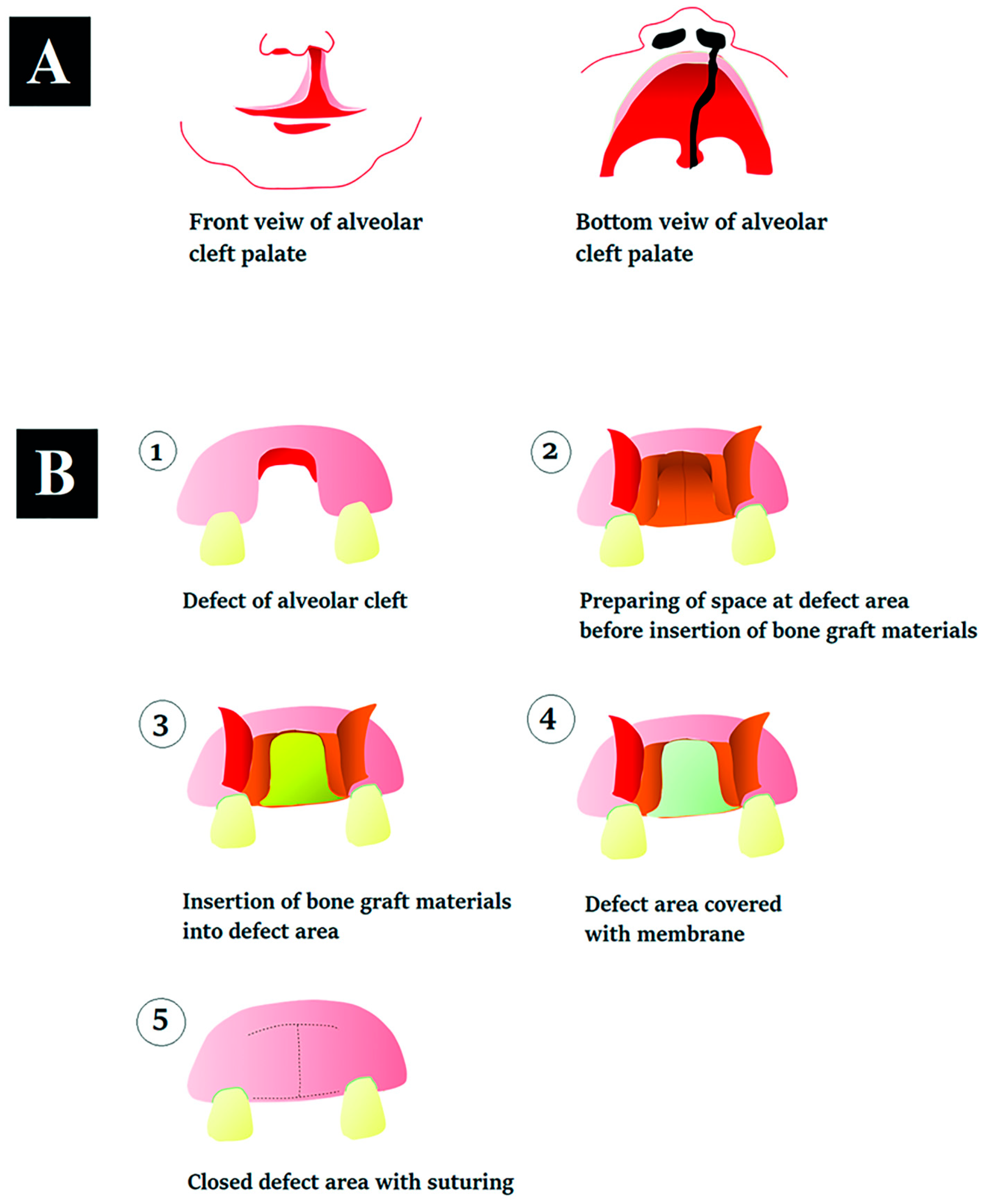
:1. Introduction
2. Materials and Methods
2.1. Preparation of the Silk Fibroin Solution
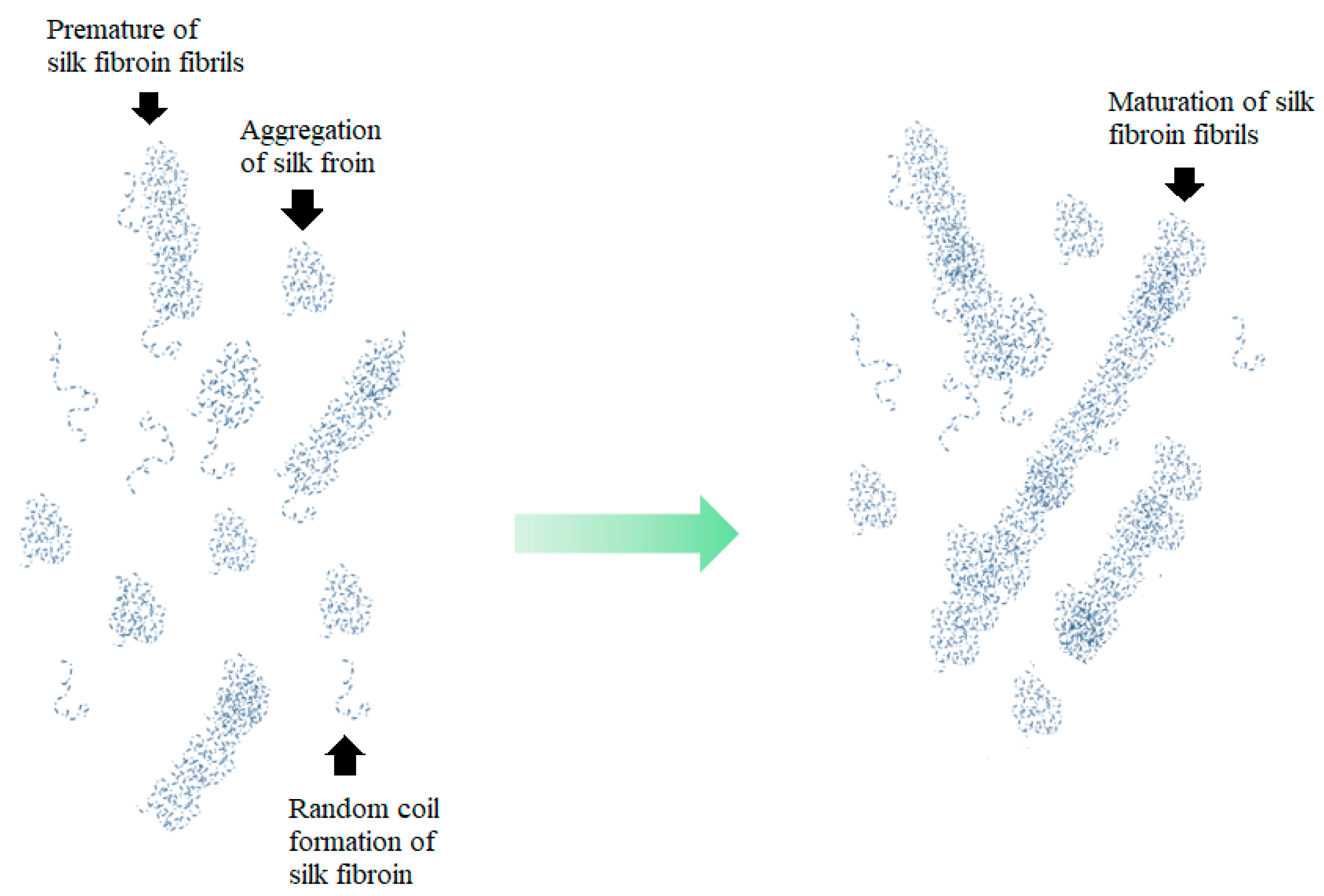
2.2. Extraction of a Mixture of Random Coil and Aggregation of Silk Fibroin
2.3. Preparation of the Silk Fibroin Fibrils
2.4. Preparation of Binders
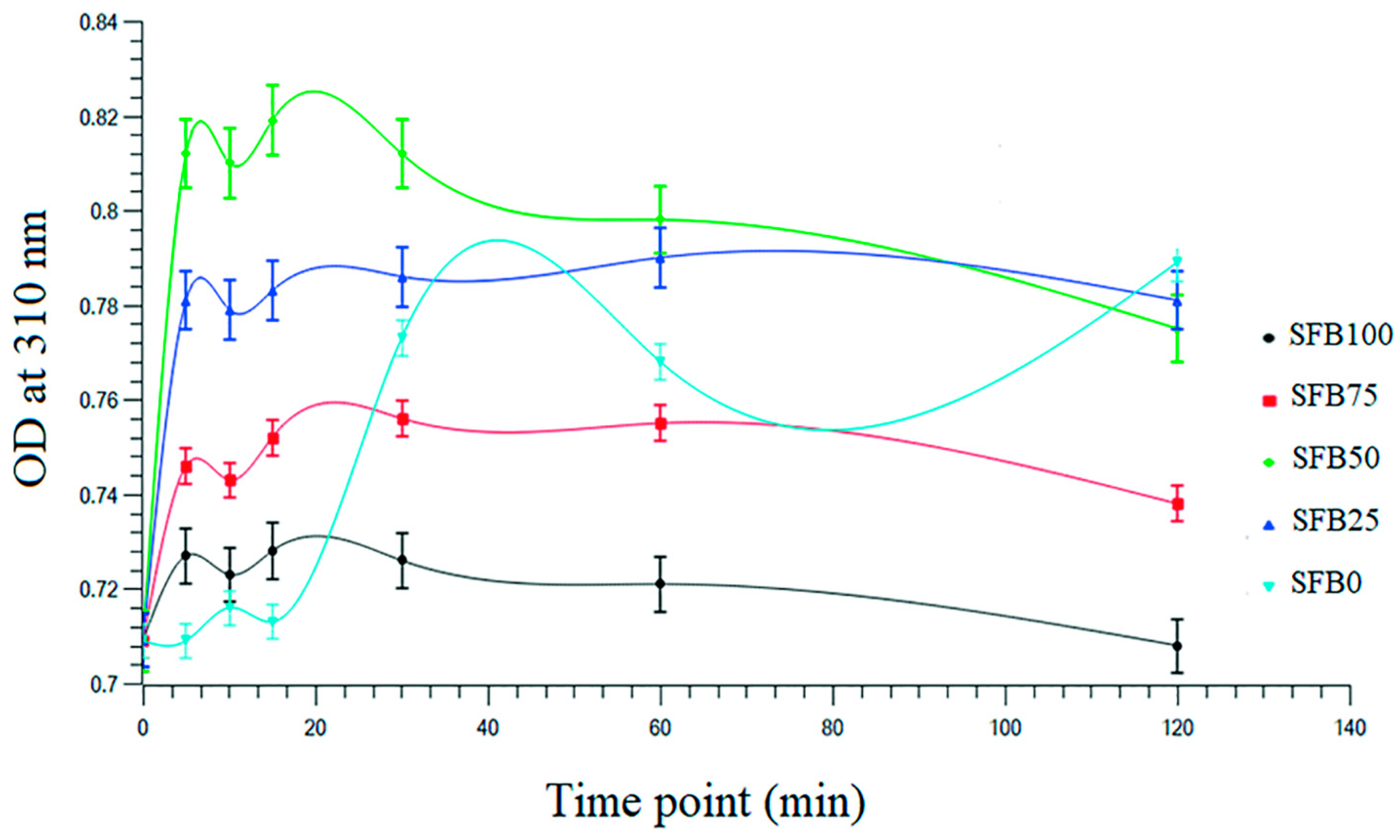
2.5. Analysis of Self-Assembly during Gelation of Binder
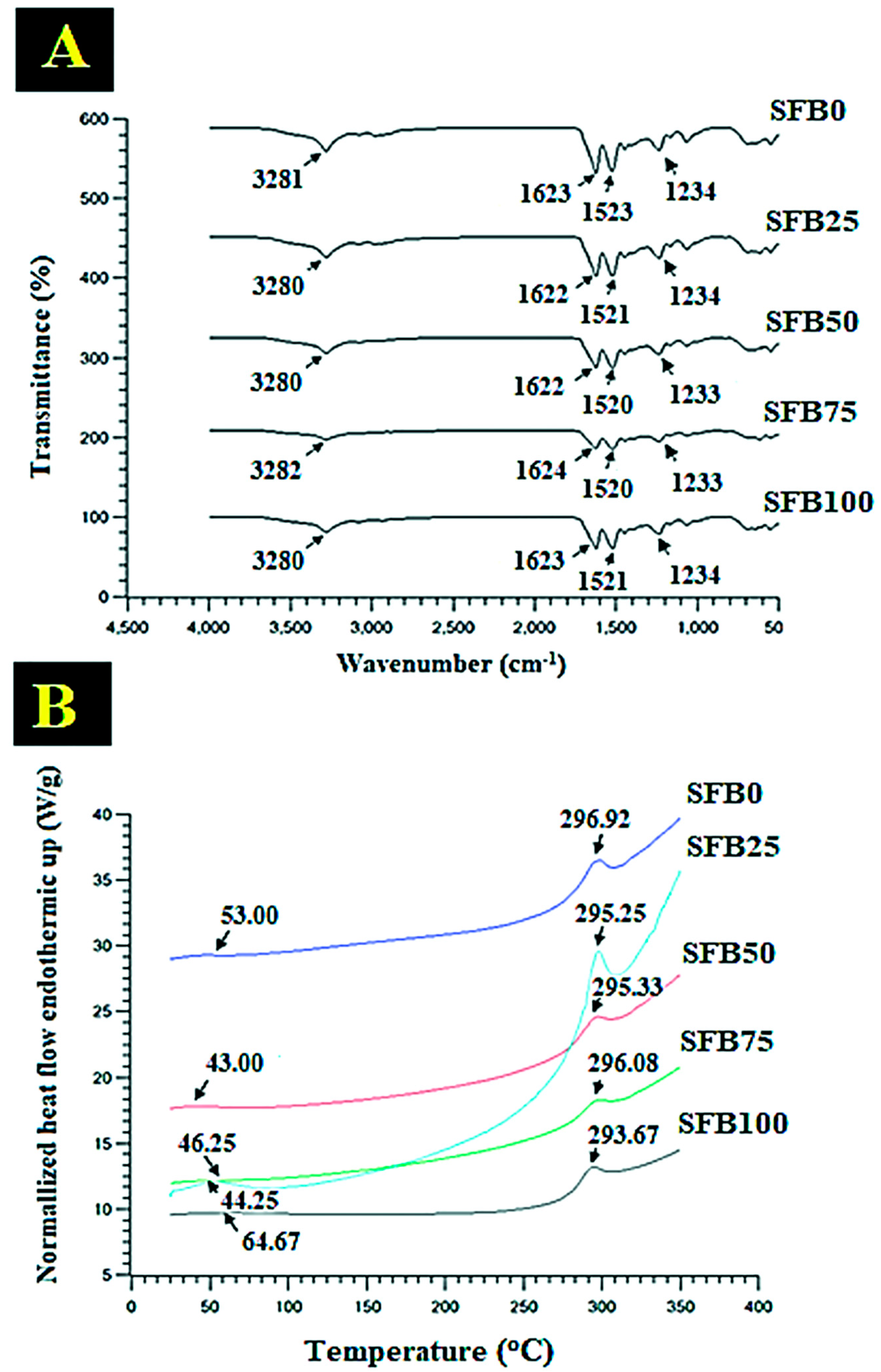
2.6. Fourier Transform Infrared (FTIR) Spectroscopy
2.7. Differential-Scanning Calorimetry (DSC)
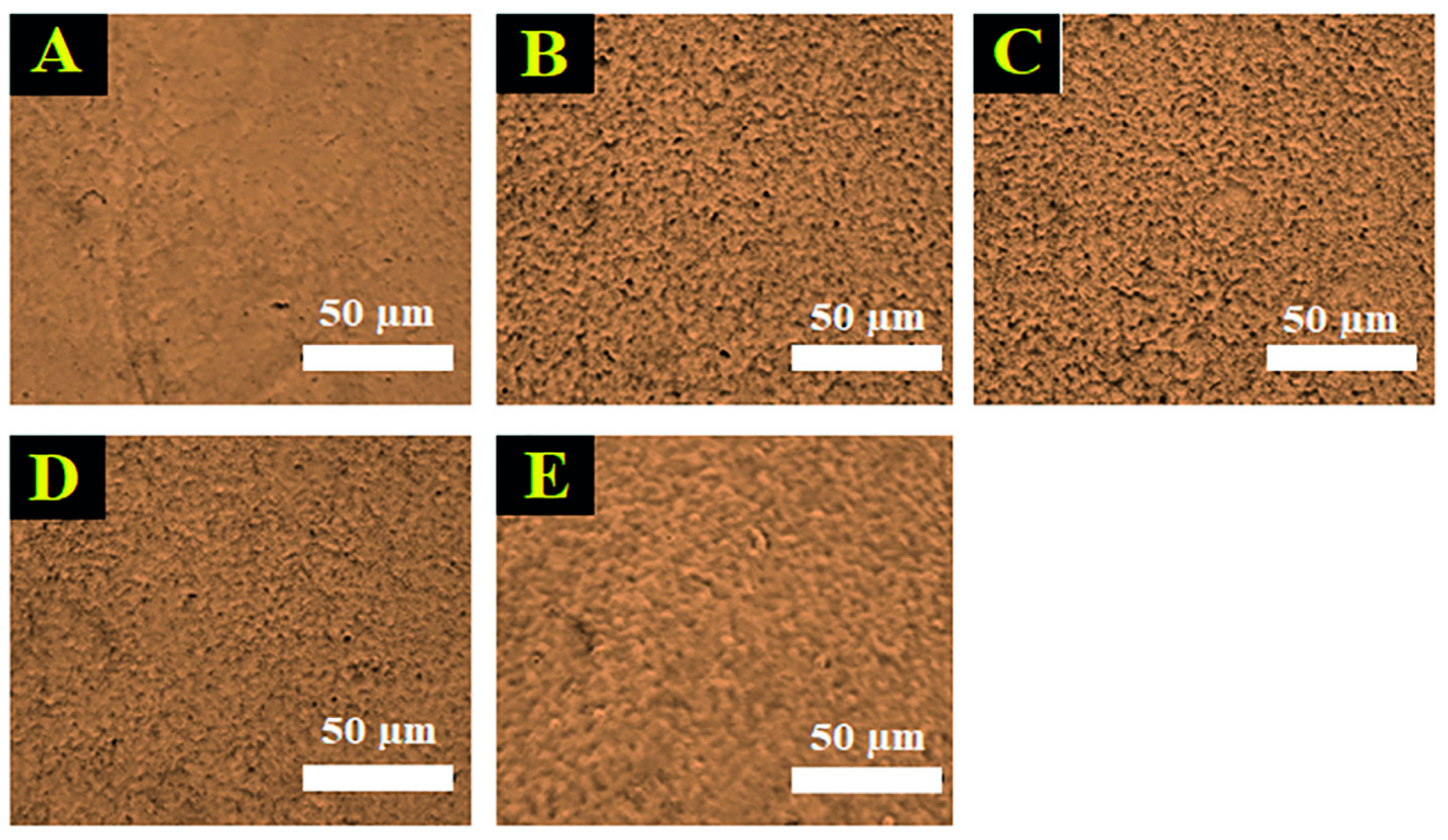
2.8. Topography and Surface Roughness Analysis
2.9. Scanning Electron Microscopy (SEM)
2.10. SF Release
2.11. Water Contact Angle
2.12. Testing the Binding Function as a Mechanical Property
2.13. Cell Culturing
2.14. Cell Proliferation
2.15. Cell Viability
2.16. Protein Synthesis
2.17. Alkaline Phosphatase (ALP) Measurement
2.18. Alizarin Red Staining
2.19. Statistical Analysis
3. Results
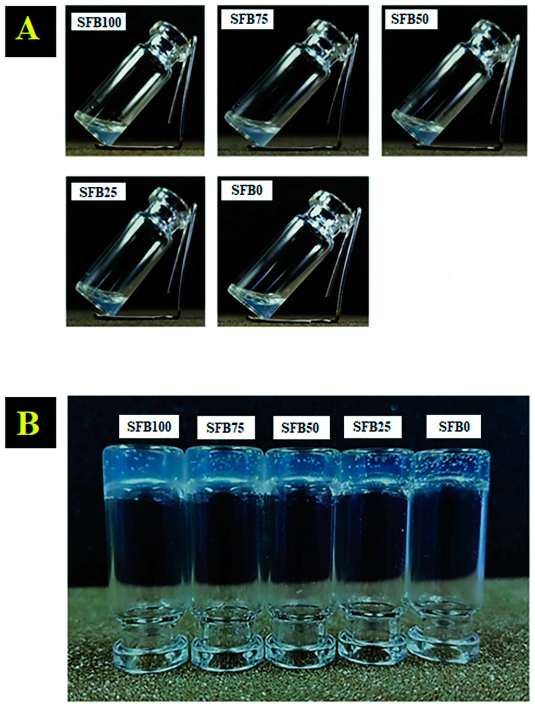
3.1. Gelation of the Silk Fibroin Binders
3.2. FTIR and DSC Characterization, Contact Angle, and Silk Fibroin Release
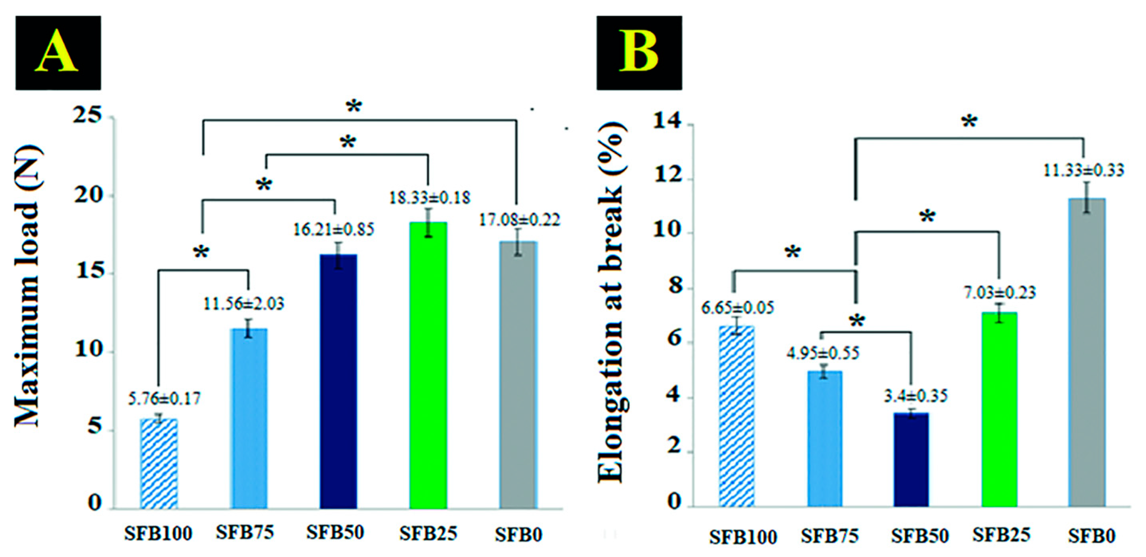
3.3. Binding Function as a Mechanical Property
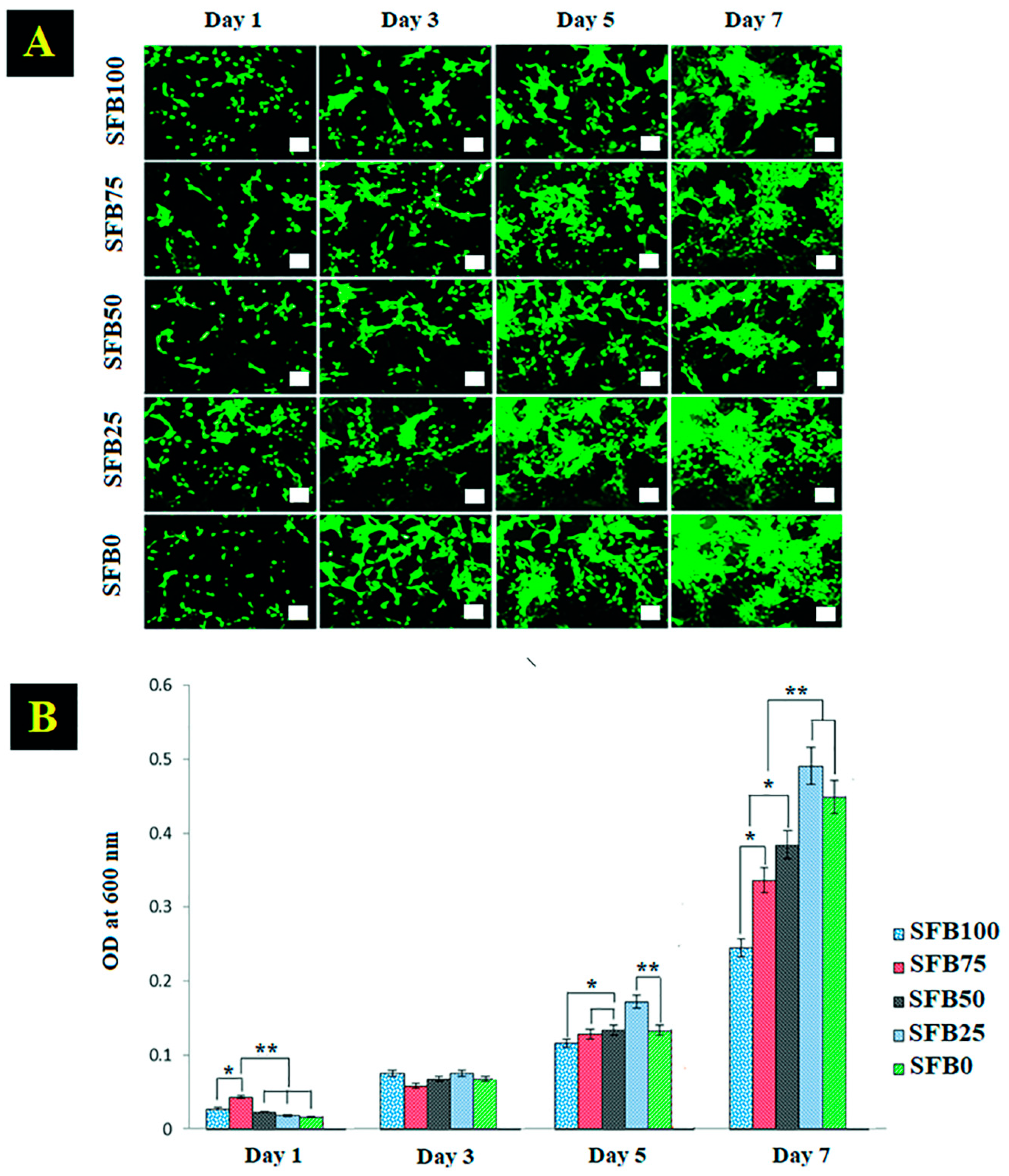
3.4. Cell Viability and Cell Proliferation
3.5. Alizarin Red Staining, Alkaline Phosphatase Activity, and Protein Synthesis
4. Discussion
5. Conclusions
Supplementary Materials
Author Contributions
Funding
Informed Consent Statement
Data Availability Statement
Acknowledgments
Conflicts of Interest
References
- Korn, P.; Ahlfeld, T.; Lahmeyer, F.; Kilian, D.; Sembdner, P.; Stelzer, R.; Pradel, W.; Franke, A.; Rauner, M.; Range, U.; et al. 3D Printing of Bone Grafts for Cleft Alveolar Osteoplasty—In vivo Evaluation in a Preclinical Model. Front. Bioeng. Biotechnol. 2020, 8, 217. [Google Scholar] [CrossRef] [PubMed]
- Gomes Ferreira, P.H.S.; De Oliveira, D.; Duailibe De Deus, C.B.; Okamoto, R. Evaluation of the Different Biomaterials Used in Alveolar Cleft Defects in Children. Ann. Maxillofac. Surg. 2018, 8, 315–319. [Google Scholar]
- Grasso, G.; Mummolo, S.; Bernardi, S.; Pietropaoli, D.; D’Ambrosio, G.; Iezzi, G.; Piattelli, A.; Bianchi, S.; Marchetti, E. Histological and Histomorphometric Evaluation of New Bone Formation after Maxillary Sinus Augmentation with Two Different Osteoconductive Materials: A Randomized, Parallel, Double-Blind Clinical Trial. Materials 2020, 13, 5520. [Google Scholar] [CrossRef] [PubMed]
- Cheah, C.W.; Al-Namnam, N.M.; Lau, M.N.; Lim, G.S.; Raman, R.; Fairbairn, P.; Ngeow, W.C. Synthetic Material for Bone, Periodontal, and Dental Tissue Regeneration: Where Are We Now, and Where Are We Heading Next? Materials 2021, 14, 6123. [Google Scholar] [CrossRef] [PubMed]
- Titsinides, S.; Agrogiannis, G.; Karatzas, T. Bone grafting materials in dentoalveolar reconstruction: A comprehensive review. Jpn. Dent. Sci. Rev. 2019, 55, 26–32. [Google Scholar] [CrossRef] [PubMed]
- Wang, W.; Yeung, K.W.K. Bone grafts and biomaterials substitutes for bone defect repair: A review. Bioact. Mater. 2017, 2, 224–247. [Google Scholar] [CrossRef]
- Neumann, A.; Kevenhoerster, K. Biomaterials for craniofacial reconstruction. GMS Curr. Top. Otorhinolaryngol. Head Neck Surg. 2009, 8, Doc08. [Google Scholar]
- Pacifici, L.; De Angelis, F.; Orefici, A.; Cielo, A. Metals used in maxillofacial surgery. Oral Implantol. 2016, 9, 107–111. [Google Scholar] [CrossRef]
- Filippi, M.; Born, G.; Chaaban, M.; Scherberich, A. Natural Polymeric Scaffolds in Bone Regeneration. Front. Bioeng. Biotechnol. 2020, 8, 474. [Google Scholar] [CrossRef]
- Nak, H.K. Current Methods for the Treatment of Alveolar Cleft. Arch Plast Surg. 2017, 44, 188–193. [Google Scholar]
- Dewi, A.H.; Ana, I.D. The use of hydroxyapatite bone substitute grafting for alveolar ridge preservation, sinus augmentation, and periodontal bone defect: A systematic review. Heliyon 2018, 4, e00884. [Google Scholar] [CrossRef] [PubMed] [Green Version]
- Xu, H.H.K.; Wang, P.; Wang, L.; Bao, C.; Chen, Q.; Weir, M.D.; Chow, L.C.; Zhao, L.; Zhou, X.; Reynolds, M.A. Calcium phosphate cements for bone engineering and their biological properties. Bone Res. 2017, 5, 17056. [Google Scholar] [CrossRef] [PubMed] [Green Version]
- Jeong, J.; Kim, J.H.; Shim, J.H.; Hwang, N.S.; Heo, C.Y. Bioactive calcium phosphate materials and applications in bone regeneration. Biomater. Res. 2019, 23, 4. [Google Scholar] [CrossRef] [PubMed] [Green Version]
- Wahl, D.A.; Czernuszka, J.T. Collagen-Hydroxyapatite Composites for Hard Tissue Repair. Eur. Cells Mater. 2006, 11, 43–56. [Google Scholar] [CrossRef] [PubMed]
- Wang, Y.; Wang, K.; Li, X.; Wei, Q.; Chai, W.; Wang, S.; Che, Y.; Lu, T.; Zhang, B. 3D fabrication and characterization of phosphoric acid scaffold with a HA/β-TCP weight ratio of 60:40 for bone tissue engineering applications. PLoS ONE 2017, 12, e0174870. [Google Scholar] [CrossRef]
- Zhong, G.; Vaezi, M.; Mei, X.; Liu, P.; Yang, S. Strategy for Controlling the Properties of Bioactive Poly-EtherEther-Ketone/Hydroxyapatite Composites for Bone Tissue Engineering Scaffolds. ACS Omega 2019, 4, 19238–19245. [Google Scholar] [CrossRef] [Green Version]
- Kamal, M.; Andersson, L.; Tolba, R.; Al-Asfour, A.; Bartella, A.K.; Gremse, F.; Rosenhain, S.; Hölzle, F.; Kessler, P.; Lethaus, B. Bone regeneration using composite non-demineralized xenogenic dentin with beta-tricalcium phosphate in experimental alveolar cleft repair in a rabbit model. J. Transl. Med. 2017, 15, 263. [Google Scholar] [CrossRef] [Green Version]
- Reynolds, M.A.; Aichelmann-Reidy, M.E.; Kassolis, J.D.; Prasad, H.S.; Rohrer, M.D. Calcium sulfate carboxymethylcellulose bone graft binder: Histologic and morphometric evaluation in a critical size defect. J. Biomed. Mater. Res. B Appl. Biomater. 2007, 83, 451–458. [Google Scholar] [CrossRef]
- Almasri, M.; Camarda, A.J.; Ciaburro, H.; Chouikh, F.; Dorismond, S.J. Preservation of Posterior Mandibular Extraction Site with Allogeneic Demineralized, Freeze-Dried Bone Matrix and Calcium Sulphate Graft Binder before Eventual Implant Placement: A Case Series. J. Can. Dent. Assoc. 2012, 78, c15. [Google Scholar]
- Lee, D.K.; Ki, M.R.; Kim, E.H.; Park, C.J.; Ryu, J.J.; Jang, H.S.; Pack, S.P.; Jo, Y.K.; Jun, S.H. Biosilicated collagen/β-tricalcium phosphate composites as a BMP-2-delivering bone-graft substitute for accelerated craniofacial bone regeneration. Biomater. Res. 2021, 25, 13. [Google Scholar] [CrossRef]
- Choi, B.H.; Cheong, H.; Ahn, J.S.; Zhou, C.; Kwon, J.J.; Cha, H.J.; Jun, S.H. Engineered mussel bioglue as a functional osteoinductive binder for grafting of bone substitute particles to accelerate in vivo bone regeneration. J. Mater. Chem. B 2015, 3, 546–555. [Google Scholar] [CrossRef] [PubMed] [Green Version]
- Panjapheree, K.; Kamonmattayakul, S.; Meesane, J. Biphasic scaffolds of silk fibroin film affixed to silk fibroin/chitosan sponge based on surgical design for cartilage defect in osteoarthritis. Mater. Des. 2018, 141, 323–332. [Google Scholar] [CrossRef]
- Nawae, S.; Meesane, J.; Muensit, N.; Daengngam, C. Layer-by-layer self-assembled films of silk fibroin/collagen/poly(diallyldimethyl ammonium chloride) as nucleating surface for osseointegration to design coated dental implant materials. Mater. Des. 2018, 160, 1158–1167. [Google Scholar] [CrossRef]
- Melke, J.; Midha, S.; Ghosh, S.; Ito, K.; Hofmann, S. Silk fibroin as biomaterial for bone tissue engineering. Acta Biomater. 2016, 31, 1–16. [Google Scholar] [CrossRef] [PubMed] [Green Version]
- Bhattacharjee, P.; Kundu, B.; Naskar, D.; Kim, H.W.; Maiti, T.K.; Bhattacharya, D.; Kundu, S.C. Silk scaffolds in bone tissue engineering: An overview. Acta Biomater. 2017, 63, 1–17. [Google Scholar] [CrossRef] [PubMed]
- Saleem, M.; Rasheed, S.; Yougen, C. Silk fibroin/hydroxyapatite scaffold: A highly compatible material for bone regeneration. Sci. Technol. Adv. Mater. 2020, 21, 242–266. [Google Scholar] [CrossRef] [Green Version]
- Moe, Y.M.; Nuntanaranont, T.; Khangkhamano, M.; Meesane, J. Mimicked Periosteum Layer Based on Deposited Particle Silk Fibroin Membrane for Osteogenesis and Guided Bone Regeneration in Alveolar Cleft Surgery: Formation and in Vitro Testing. Organogenesis 2021, 17, 1–17. [Google Scholar] [CrossRef]
- Koh, K.S.; Choi, J.W.; Park, E.J.; Oh, T.S. Bone Regeneration using Silk Hydroxyapatite Hybrid Composite in a Rat Alveolar Defect Model. Int. J. Med. Sci. 2018, 15, 59–68. [Google Scholar] [CrossRef] [Green Version]
- Johnston, E.R.; Miyagi, Y.; Chuah, J.A.; Numata, K.; Serban, M.A. The interplay between silk fibroin’s structure and its adhesive Properties. ACS Biomater. Sci. Eng. 2018, 13, 2815–2824. [Google Scholar] [CrossRef]
- Zheng, H.; Zuo, B. Functional silk fibroin hydrogels: Preparation, properties and applications. J. Mater. Chem. B 2021, 9, 1238–1258. [Google Scholar] [CrossRef]
- Yin, Z.; Wu, F.; Xing, T.; Yadavalli, V.K.; Kundu, S.C.; Lu, S. A silk fibroin hydrogel with reversible sol–gel transition. RSC Adv. 2017, 39, 85–24096. [Google Scholar] [CrossRef] [Green Version]
- Ling, S.; Qin, Z.; Huang, W.; Cao, S.; Kaplan, D.L.; Buehler, M.J. Design and function of biomimetic multilayer water purification membranes. Sci. Adv. 2017, 3, e1601939. [Google Scholar] [CrossRef] [PubMed] [Green Version]
- Jean, P.; Douaud, A.; Larochelle, S.; Messaddeq, Y.; Shi, W. Templated dewetting for self-assembled ultra-low-loss chalcogenide integrated photonics. Opt. Mater. Express 2021, 11, 3717–3735. [Google Scholar] [CrossRef]
- Gonzalez, J.S.; Mijangos, C.; Hernandez, R. Polysaccharide Coating of Gelatin Gels for Controlled BSA Release. Polymers 2019, 11, 702. [Google Scholar] [CrossRef] [PubMed] [Green Version]
- Li, T.T.; Ebert, K.; Vogel, J.; Groth, T. Comparative studies on osteogenic potential of micro- and nanofibre scaffolds prepared by electrospinning of poly(ε-caprolactone). Prog. Biomater. 2013, 2, 13. [Google Scholar] [CrossRef] [PubMed] [Green Version]
- Jaromır, H.; Martin, P.; Jan, S.; Jan, Z.; Karel, B. Polymer anion selective membranes for electrolytic splitting of water. Part I: Stability of ion-exchange groups and impact of the polymer binder. J. Appl. Electrochem. 2011, 41, 1043–1052. [Google Scholar]
- Wei, K.; Kim, B.S.; Kim, I.S. Fabrication and Biocompatibility of Electrospun Silk Biocomposites. Membranes 2011, 1, 275–298. [Google Scholar] [CrossRef] [Green Version]
- Mensch, C.; Bultinck, P.; Johannessen, C. The effect of protein backbone hydration on the amide vibrations in Raman and Raman optical activity spectra. Phys. Chem. Chem. Phys. 2019, 21, 1988–2005. [Google Scholar] [CrossRef] [Green Version]
- Sadat, A.; Joye, I.J. Peak Fitting Applied to Fourier Transform Infrared and Raman Spectroscopic Analysis of Proteins. Appl. Sci. 2020, 10, 5918. [Google Scholar] [CrossRef]
- Balan, V.; Mihai, C.T.; Cojocaru, F.D.; Uritu, C.M.; Dodi, G.; Botezat, D.; Gardikiotis, I. Vibrational Spectroscopy Fingerprinting in Medicine: From Molecular to Clinical Practice. Materials 2019, 12, 2884. [Google Scholar] [CrossRef] [Green Version]
- Zhang, H.; Li, L.L.; Dai, F.Y.; Zhang, H.H.; Ni, B.; Zhou, W.; Yang, X.; Wu, Y.Z. Preparation and characterization of silk fibroin as a biomaterial with potential for drug delivery. J. Transl. Med. 2012, 10, 117. [Google Scholar] [CrossRef] [PubMed] [Green Version]
- Kamalha, E.; Zheng, Y.; Zeng, Y.; Fredrick, M.N. FTIR and WAXD study of regenerated silk fibroin. Adv. Mater. Res. 2013, 677, 211–215. [Google Scholar] [CrossRef]
- Liu, Q.; Wang, F.; Gu, Z.; Ma, Q.; Hu, X. Exploring the Structural Transformation Mechanism of Chinese and Thailand Silk Fibroin Fibers and Formic-Acid Fabricated Silk Films. Int. J. Mol. Sci. 2018, 19, 3309. [Google Scholar] [CrossRef] [PubMed] [Green Version]
- Baimark, Y.; Srisa-ard, M.; Srihanam, P. Morphology and thermal stability of silk fibroin/starch blended microparticles. Express Polym. Lett. 2010, 4, 781–789. [Google Scholar] [CrossRef]
- Fan, L.; Li, J.L.; Cai, Z.; Wang, X. Bioactive hierarchical silk fibers created by bioinspired self-assembly. Nat. Commun. 2021, 12, 2375. [Google Scholar] [CrossRef] [PubMed]
- Lee, C.C.; Nayak, A.; Sethuraman, A.; Belfort, G.; McRae, J. A Three-Stage Kinetic Model of Amyloid Fibrillation. Biophys. J. 2007, 92, 3448–3458. [Google Scholar] [CrossRef] [Green Version]
- Weisel, J.W.; Litvinov, R.I. Fibrin Formation, Structure and Properties. Fibrous Proteins Struct. Mech. 2017, 82, 405–456. [Google Scholar]
- Utech, S.; Boccaccini, A.R. A review of hydrogel-based composites for biomedical applications: Enhancement of hydrogel properties by addition of rigid inorganic fillers. J. Mater. Sci. 2016, 51, 271–310. [Google Scholar] [CrossRef]
- Chen, H.; Han, Q.; Wang, C.; Liu, Y.; Chen, B.; Wang, J. Porous Scaffold Design for Additive Manufacturing in Orthopedics: A Review. Front. Bioeng. Biotechnol. 2020, 8, 609. [Google Scholar] [CrossRef]
- Heino, J. The collagen family members as cell adhesion proteins. BioEssays 2007, 29, 1001–1010. [Google Scholar] [CrossRef]
- Loh, Q.L.; Choong, C. Three-Dimensional Scaffolds for Tissue Engineering Applications: Role of Porosity and Pore Size. Tissue Eng. Part B Rev. 2013, 19, 485–502. [Google Scholar] [CrossRef] [PubMed] [Green Version]
- Bacakova, L.; Filova, E.; Parizek, M.; Ruml, T.; Svorcik, V. Modulation of cell adhesion, proliferation and differentiation on materials designed for body implants. Biotechnol. Adv. 2011, 29, 739–767. [Google Scholar] [CrossRef] [PubMed]
- Damanik, F.F.R.; Rothuizen, T.C.; Blitterswijk, C.V.; Rotmans, J.I.; Moroni, L. Towards an in vitro model mimicking the foreign body response: Tailoring the surface properties of biomaterials to modulate extracellular matrix. Sci. Rep. 2014, 4, 6325. [Google Scholar] [CrossRef] [PubMed] [Green Version]
- Menzies, K.L.; Jones, L. The Impact of Contact Angle on the Biocompatibility of Biomaterials. Optom. Vis. Sci. 2010, 87, 387–399. [Google Scholar] [CrossRef] [PubMed]
- Wilson, C.J.; Clegg, R.E.; Leavesley, D.I.; Pearcy, M. Mediation of Biomaterial–Cell Interactions by Adsorbed Proteins: A Review. Tissue Eng. 2005, 11, 1–19. [Google Scholar] [CrossRef] [PubMed]
- Chen, L.; Yan, C.; Zheng, Z. Functional polymer surfaces for controlling cell behaviors. Mater. Today 2018, 21, 38–59. [Google Scholar] [CrossRef]
- Wang, X.; Kluge, J.; Leisk, G.G.; Kaplan, D.L. Sonication-Induced Gelation of Silk Fibroin for Cell Encapsulation. Biomaterials 2008, 29, 1054–1064. [Google Scholar] [CrossRef] [Green Version]
- Rajak, D.K.; Pagar, D.D.; Kumar, R.; Pruncu, C.I. Recent progress of reinforcement materials: A comprehensive overview of composite materials. J. Mater. Res. Technol. 2019, 8, 6354–6374. [Google Scholar] [CrossRef]
- Arun, K.S.; Rakesh, B.; Amit, A.; Ruta, R. Matrix materials used in composites: A comprehensive study. Mater. Today Proc. 2020, 21, 1559–1562. [Google Scholar]
- Çalin, R.; Muharrem, P.; Çitak, R.; Şeker, U. The Effect of Reinforcement Ratio on the Composite Structure and Mechanical Properties in Al-MgO Composites Produced by the Melt Stirring Method. Adv. Compos. Mater. 2011, 20, 096369351102000401. [Google Scholar] [CrossRef] [Green Version]
- Rajak, D.K.; Pagar, D.D.; Menezes, P.L.; Linul, E. Fiber-Reinforced Polymer Composites: Manufacturing, Properties, and Applications. Polymers 2019, 11, 1667. [Google Scholar] [CrossRef] [PubMed] [Green Version]
- Nava, M.M.; Draghi, L.; Giordano, C.; Pietrabissa, R. The effect of scaffold pore size in cartilage tissue engineering. J. Appl. Biomater. Funct. Mater. 2016, 14, e223–e229. [Google Scholar] [CrossRef] [PubMed] [Green Version]
- Weber, F.E. Reconsidering Osteoconduction in the Era of Additive Manufacturing. Tissue Eng. Part B Rev. 2019, 25, 375–386. [Google Scholar] [CrossRef] [PubMed]
- Khodakaram-Tafti, A.; Mehrabani, D.; Shaterzadeh-Yazdi, H. An overview on autologous fibrin glue in bone tissue engineering of maxillofacial surgery. Dent. Res. J. 2017, 14, 79–86. [Google Scholar]
- Buckley, J.M.; Beckman, E.J. Adhesive Use in Oral and Maxillofacial Surgery. Oral Maxillofac. Surg. Clin. 2010, 22, 195–199. [Google Scholar] [CrossRef]
- Mo, X.; Iwata, H.; Ikada, Y. A tissue adhesives evaluated in vitro and in vivo analysis. J. Biomed. Mater. Res. Part A 2010, 94, 326–332. [Google Scholar] [CrossRef]
- Noori, A.; Ashrafi, S.J.; Vaez-Ghaemi, R.; Hatamian-Zaremi, A.; Webster, T.J. A review of fibrin and fibrin composites for bone tissue engineering. Int. J. Nanomed. 2017, 12, 4937–4961. [Google Scholar] [CrossRef] [Green Version]


| Binder Groups | Details |
|---|---|
| SFB100 | Mixture of random coils and aggregation of silk fibroin/silk fibroin fibrils (100:0) |
| SFB75 | Mixture of random coils and aggregation of silk fibroin/silk fibroin fibrils (75:25) |
| SFB50 | Mixture of random coils and aggregation of silk fibroin/silk fibroin fibrils (50:50) |
| SFB25 | Mixture of random coils and aggregation of silk fibroin/silk fibroin fibrils (25:75) |
| SFB0 | Mixture of random coils and aggregation of silk fibroin/silk fibroin fibrils (0:100) |
Publisher’s Note: MDPI stays neutral with regard to jurisdictional claims in published maps and institutional affiliations. |
© 2022 by the authors. Licensee MDPI, Basel, Switzerland. This article is an open access article distributed under the terms and conditions of the Creative Commons Attribution (CC BY) license (https://creativecommons.org/licenses/by/4.0/).
Share and Cite
Sangkert, S.; Juncheed, K.; Meesane, J. Osteoconductive Silk Fibroin Binders for Bone Repair in Alveolar Cleft Palate: Fabrication, Structure, Properties, and In Vitro Testing. J. Funct. Biomater. 2022, 13, 80. https://doi.org/10.3390/jfb13020080
Sangkert S, Juncheed K, Meesane J. Osteoconductive Silk Fibroin Binders for Bone Repair in Alveolar Cleft Palate: Fabrication, Structure, Properties, and In Vitro Testing. Journal of Functional Biomaterials. 2022; 13(2):80. https://doi.org/10.3390/jfb13020080
Chicago/Turabian StyleSangkert, Supaporn, Kantida Juncheed, and Jirut Meesane. 2022. "Osteoconductive Silk Fibroin Binders for Bone Repair in Alveolar Cleft Palate: Fabrication, Structure, Properties, and In Vitro Testing" Journal of Functional Biomaterials 13, no. 2: 80. https://doi.org/10.3390/jfb13020080
APA StyleSangkert, S., Juncheed, K., & Meesane, J. (2022). Osteoconductive Silk Fibroin Binders for Bone Repair in Alveolar Cleft Palate: Fabrication, Structure, Properties, and In Vitro Testing. Journal of Functional Biomaterials, 13(2), 80. https://doi.org/10.3390/jfb13020080