Article

District-Heating-Grid Simulation in Python: DiGriPy

Fraunhofer Institute for Manufacturing Technology and Advanced Materials IFAM, Wiener Straße 12, 28359 Bremen, Germany
*
Author to whom correspondence should be addressed.
Computation 2021, 9(6), 72; https://doi.org/10.3390/computation9060072
Submission received: 6 May 2021 / Revised: 10 June 2021 / Accepted: 10 June 2021 / Published: 16 June 2021
(This article belongs to the Section Computational Engineering)

Abstract

:
DiGriPy is a newly developed Python tool for the simulation of district heating networks published as open-source software in GitHub and offered as a Python package on PyPI. It enables the user to easily build a network model, run large-scale demand time series, and automatically compare different temperature-control conditions. In this paper, implementation details and usage instructions are given. Tests showing the results of different scenarios are presented and interpreted.

1. Introduction and Motivation

By signing the Paris Agreement, 196 parties expressed their will to limit temperature increases due to climate change to well below 2 °C and preferably below 1.5 °C. Therefore, strong reductions in the emission of greenhouse gases are required. The overall aim is to reach net zero emissions by 2050 [1]. Reaching this goal needs strong and fast action in all sectors, while in many countries, the main focus has only been on decarbonizing the electricity sector. One example is the German Energiewende, where efforts to decarbonize the electricity sector led to an increase in the share of renewables from 6.3% in 2000 to 42% in 2019. The share of renewables in the mobility sector accounts for about 5.5.%, and in the heat sector for 15%. Both sectors have basically stagnated since 2012 [2]. The heat sector covers about 50% of energy end use in Germany, with 57% of this share being used for space heating and hot water [2]. Thus, it is crucial to put strong efforts in this sector to achieve German climate goals and fulfil the Paris Agreement. The same trend can be found for the European Union. A series of studies covered under the title of “Heat Roadmap Europe” focus on the European heat market. Within these studies, data were collected, the current heat and cooling market was analysed, and guidelines and transformation strategies were derived [3]. A motivation for these studies is the large share of waste heat in electricity production, which equals the amount of heat needed for all buildings. This holds true even though the share of heat consumption equals 49 % of total energy consumption, with 27 % of the heat being used for space heating and 4 % for hot water. In all European countries, the share of heat provided by district heat equals 9 % , and the share of heat covered by renewable energy equals 13 % [4]. A large potential share of district heating in the heating sector was found to be in the range of 32–68% across the analyzed countries [5]. Current studies concerning transformation scenarios indicate two essential factors for a transition of the heat sector. First, reducing demand by increasing efforts in renovation, i.e., efficiency, and a trend reversal in residential space requirements, i.e., sufficiency. Second, increasing the share of renewables for the remaining heat demand [5,6,7,8]. While burning gas or coal produces heat at high temperature levels, most renewable heat sources provide heat at low temperatures. Typical decentralized solar thermal collectors provide hot water at temperature levels below 100 °C [9]. Heat pumps have higher coefficients of performance when the temperature lift is small. In Germany, most installed heat pumps use air as the heat source, such that the heat-source temperature is low, especially in winter when heating is needed [10]. There is also dependence on the weather, for example, with respect to solar radiation or air temperature, which leads to fluctuating heat production. This is not the case for burning fossils as long as the supply chain is not interrupted. Providing reliable heat from renewable-energy sources is more challenging.
In a study on the German heating market, the fourth generation of heating grids was analyzed, transformation targets were defined, and necessary steps towards efficient heating supply and decarbonized heat were derived. A potential for fourth-generation grids was found, even under the consideration of high infrastructure costs and the heterogeneous building stock; when renovation measures are taken into account, that reduces the specific heat demand of buildings. The efficiency and cost of district heating grids based on renewable heat sources can be improved if detailed information about the heat-demand profile and heat losses in the grid is already known in the planning process [11].
In this work, a developed open-source tool is presented that allows for the simulation of district heating grids, computing the needed heat fed into the grid at each considered time step. There are various tools for simulating district heating grids on the market, e.g., ROKA 3 [12] and NEPLAN [13]. Most proprietary software has a broad range of applications, allowing for detailed hydraulic simulations of heating grids and offering extensive libraries for a wide variety of components. However, this is not open-source software. There are also open-source tools aiming at district energy, such as THERMOS [14] and DHNx [15,16]. THERMOS was designed to enable municipalities and administrations to assess the economic efficiency and potential of district heating without too much detailed technical knowledge. Different heat sources can be considered, and complete analysis of a district heating grid can be performed. However, the user has rather little influence on the layout of the district heating grid, which is also due to the user group for which the tool was developed. DHNx has two main functions: first, the optimization of the layout in terms of routing and dimensioning of district heating grids; and second, hydraulic and thermal simulations. For the second part, where DiGriPy can also be used, boundary conditions such as mass flow and temperature at the consumers must be specified by the user. This is not the case with DiGriPy, where mass flow, velocity, and temperature distribution are part of the solution. DiGriPy allows for the calculation of heat losses and different operating modes; temperature levels and insulation levels can be considered and compared. Inputs for the tool are demand time series for each connected building and the dimensioning of the heat grid, i.e., pipe dimensions and insulation level. The tool then calculates the needed amount and temperature level of the heat fed in at the heat source, taking into account heat losses along the heat grid. Such results can be used for optimizing district energy systems while considering renewable heat sources [17].
In Section 2, the main idea and implemented equations are presented. Validation calculations are also explained. Section 3 details the implementation, and Section 4 shows a test case and parameter study conducted with the developed tool. The paper ends with a conclusion and outlook in Section 5, also indicating possible next steps.

2. Tool Setup and Underlying Equations

The aim of the developed tool is to enable the simulation of heat grids on the basis of the heat-demand time series of the connected buildings and the grid dimensioning, i.e., pipe geometry and insulation. The main result is a time series for the heat source giving the needed amount of heat for each time step, taking into account heat losses along the grid and heat demands. In order to reach this result, the temperature along the pipes, pressure, and flow velocity are solved at each time step. The main equations used in this tool are based on the planing manual district heating published by Swiss Energy [18]. They are summarized below.
Heat-loss flux Q ˙ can be calculated as a product of temperature gradient Δ T , conductance U. and surface A, along which heat is transferred following
Q ˙ = U · Δ T · A .
Most heat grids are built using one supply and one return pipe that are laid side by side in the ground. A schematic view is shown in Figure 1.
The relevant temperatures are supply and return temperature T S and T R , respectively, and the temperature of the surrounding soil T S o . The heat flux from pipe to soil depends on the thermal conductivity of the insulation of pipe λ I and of soil λ S , while the thermal conductivity of the inner pipe material and pipe jacket are neglected due to their marginal influence. Laying depth d is measured from the ground to the center of the pipes, and covering depth d c is measured from the ground to the upper most extent of the pipe. The distance between supply and return pipe is measured from the center of each pipe d M and from the outer surface of the pipes d o . Lastly, inner pipe radius r i n and outer pipe radius r o are shown.
Relevant surface A of a system of two pipes is given by
A = 2 · 2 · Π · L · r i n = 4 · π · L · r i n ,
with L being the length of the pipe. Temperature difference
Δ T = T F T S o = T S + T R 2 T S o
is calculated on the basis of operating fluid temperature T F of the two pipes, i.e., the mean temperature of the supply and return pipe, and the temperature of the soil. Conductance
U = 1 r i n λ I · ln r o r i n + r i n λ S · ln 4 d c + r o r o + r i n λ S · ln 2 d c + r o d o + 2 r o 2 + 1 0.5
is calculated on the basis of the conductance of insulation, the conductance of the soil, and the influence of the two pipes on each other. Some of the needed values are defined in the tool and are based on data given in Nussbaumer et al. [18], but they can be adopted by the user using input file settings.csv. These are soil conductivity λ S = 1.2 W/(mK), insulation conductivity λ I = 0.03 W/(mK), average covering depth d c = 0.6 m, and outer distance between pipes d o = 0.2 m.
The tool has a library for geometric values of common district heat pipes, for example, plastic jacket pipes (PJP), distinguished according to insulation level and nominal diameter (DN). PJP1 and PJP3 thus refer to pipes of the type PJP with an insulation level of 1 and 3, respectively. For each pipe type, geometric values are sorted by DN. The library can easily be expanded if other pipes are used and if the needed values are known. Values in the library are based on the product information of district pipes from pipe manufacturers and are given in Nussbaumer et al. [18]. Therefore, a necessary input when using the tool is the definition of the pipe type, which then leads to a set of parameters of the pipe radii and insulation thickness. The equations for the heat flux of district heating pipes (Equations (1)–(4)) were implemented in DiGriPy. Other equations for solving a pipe system, for example, the equations for pressure loss and mass-flow distribution, are available in TESPy [19] and are used within DiGriPy. The equations of state are solved for the fluid at each defined element of the heating grid. The calculation of heat losses was implemented as a postprocessing step in the pipe elements by multiplying the loss of enthalpy with the mass flow.

Validation

Empirical values of q ˙ p for the most common pipe types can be found in Nussbaumer et al. [18]. They are used for the validation calculations of the tool on the basis of the test cases defined in Section 4. With empirical values of q ˙ p , heat-loss flux
Q ˙ = q ˙ p · Δ T · L
can be directly calculated without solving for conductance U. With this equation, a constant minimal heat loss is calculated as soon as Δ T reaches the minimal value, i.e., the difference of the soil temperature and the mean value of the lower limits of the supply and return temperature.
For validation, the grid definitions of the test cases are used with Equation (5) and according to values of q ˙ p . The results of these calculations are then compared with the results obtained with DiGriPy.
DiGriPy calculations are more detailed than validation calculations are, as the fluid state is solved for at each element of the heating grid. This way, the temperature levels at each element of the heating grid are calculated, as well as velocities and pressure. The validation therefore is only done on base of the results for the heat loss. Validation calculations are also only possible with empirical values for q ˙ p .

3. Implementation and Usage

DiGriPy is implemented as a Python tool using the TESPy package [19] as a back end for the thermodynamic calculations and the underlying network model. The following subsections describe some of the details from a user’s perspective, and explain how the tool can be used.

3.1. Network Creation

The internal network representation, which is based on a TESPy network and solely consists of TESPy components, was built according to the network’s pipe information given in the network.csv file (an example file is shown in Table A1 in Appendix A). Each row in this file represents a pipe section with both the supply and the return direction. It is defined by its unique ID, the ID of the pipe from which it is fed, its length, its diameter DN class, and a binary value indicating whether it is connected in a 90 ° angle. If that value is set to 0, this means the pipe is connected straightly. Angles different from 0 ° and 90 ° are not supported. A prior pipe ID value of 0 indicates the heat source rather than a pipe. Multiple heat sources are not yet supported. This is all necessary information for a district heating network to be created. Merger and splitter objects are generated on the basis of the number of “child” pipes and represent pipe junctions. Consumer objects are created where a pipe is not set as any other prior pipe and are named similar to the pipe ID. They are represented as a TESPy “simple heat exchanger” object. To model the pressure losses due to couplings, valves with a friction coefficient matching a straight or 90 ° coupling are inserted if the flag for creating couplings is set in the settings.csv file (an example is given in Table A2). However, the effect on the result of the computation was found to be small, while the computation itself tended to become less stable. Therefore, the test cases were calculated without pressure losses at the couplings.

3.2. Required Simulation Input Data and Assumptions

The defined network must supply heat covering the demands of the connected buildings. The time series for the demands of each building are defined in the demands.csv file. The first column provides a time stamp for each frame, and each consumer is represented with a column with its ID as a header and demands in [ W ] . An example is shown in Table A3.
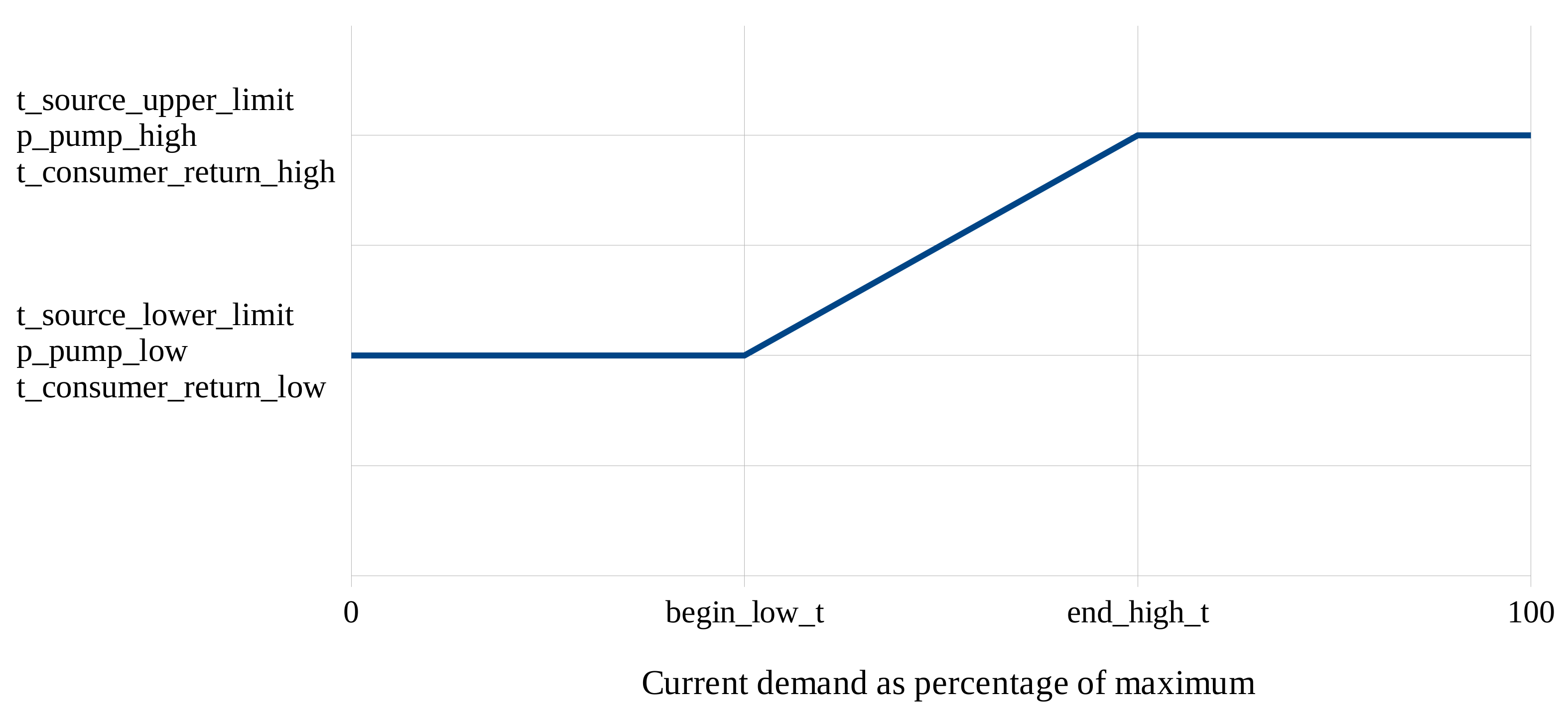
Further necessary definitions are given in settings.csv, which allows for several simulation scenarios. While the aforementioned data are constant over these settings, the following parameters can be altered between those scenarios to easily compute and compare results between different control approaches. Ambient temperature, a flag to toggle the pressure-drop simulation of couplings, and some parameters that address the control system can be set in the file. A constant-floating operational mode was implemented for the control system that can be set via these parameters for the heat-source temperature and the pump (see Figure 2 for how these parameters can be used). This also allows for a constant operational mode when upper and lower limits are set to be equal.
The settings file also gives information on pipe type, insulation level, the distance between supply and return pipe, the depth in which the pipes are buried, and the thermal conductivity of both the pipe insulation and the surrounding soil. These parameters are used for the calculation of each pipe’s heat-transition coefficient as described in Section 2. A minimal value for consumer demands can be set that overrides lower demand values. Reaching a value of 0 W at the consumer object is achieved by completely closing the valve in front of the pipe to the consumer. This, however, might prevent the tool from finding a valid solution due to convergence problems. Minimal values in the order of 10 W can noticeably improve simulation stability. Overall results are barely influenced by this, as heat losses in connection with low heat demand are of little significance, in contrast to those of high heat demand. The user must decide whether to use a minimal value for the simulated period. If a whole year with large heat demands in winter is simulated, as is the case in the presented test cases, the assumption of a minimal value is acceptable. If only summer days are simulated, this may be different. Then, boundary conditions can be defined with a focus on low heat demands, so that convergence problems with boundary conditions that must cover the whole year can be mitigated.
Besides these definitions, one more thing is assumed. To control mass flow to each consumer, a control valve is located at the input of the consumer. The aperture of the control valves is represented by its output-to-input pressure ratio. For the consumer with the highest current demand, this value is set to a fixed value that is also defined in settings.csv. To ensure that similar demand values do not lead to pressure ratios that are greater than 1, that fixed pressure ratio should be set to a value that is noticeably smaller than 1. As this means the error in the system’s pressure losses would rise, this is considered to be a workaround that will be reworked in a future release. All other control valves’ pressure ratios are derived from this value.

3.3. Calculation Process

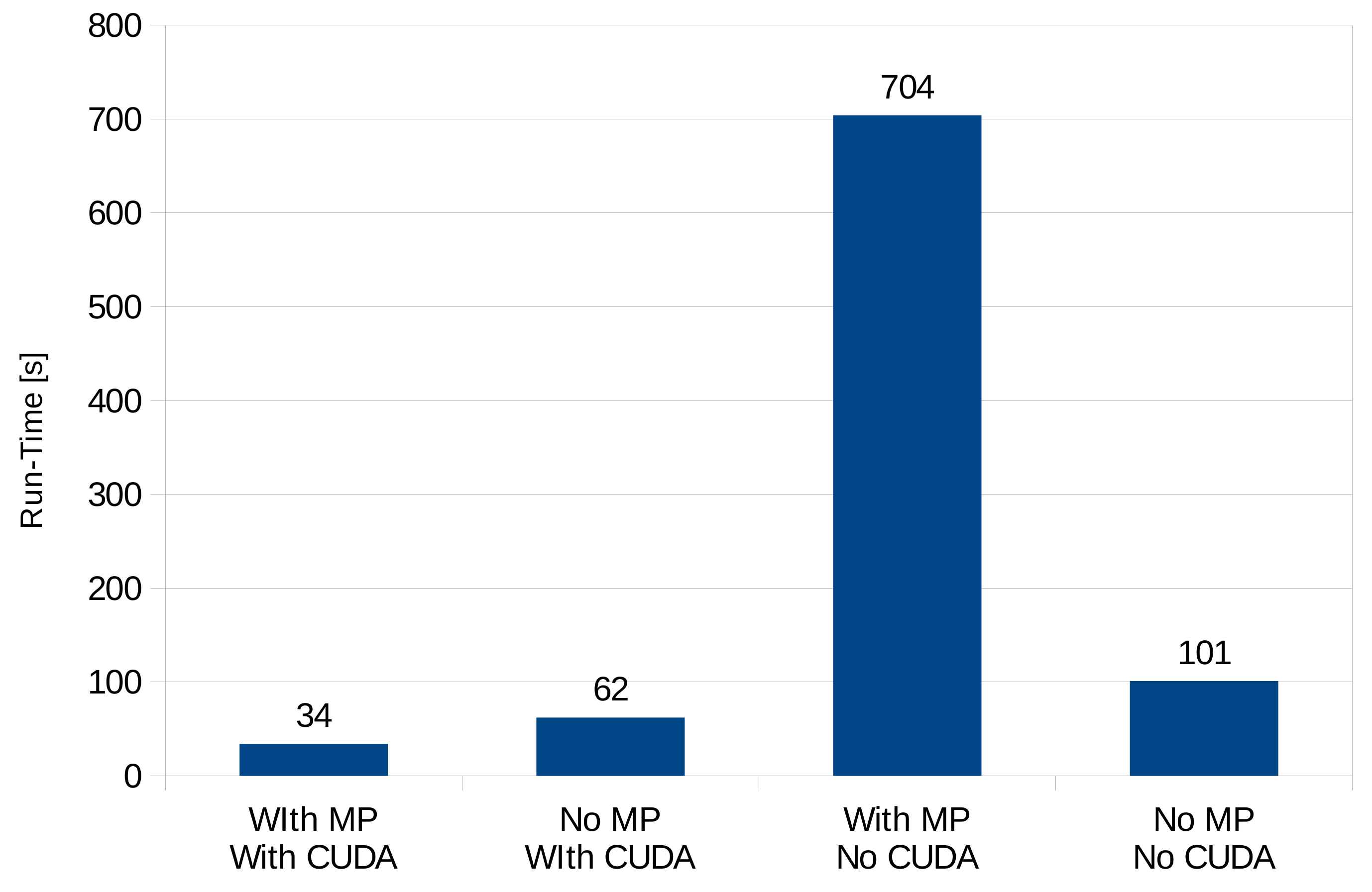
When the calculation process is started, a simulation object and a network object are generated for every simulation setting, so a parallel run is possible without the runs interfering each other. In order to make use of that fact, multiprocessing capability was implemented that starts a unique process for every simulation setting. While the Python GIL Lock would prevent the script from running multiple threads at a time when using multithreading, multiprocessing allows for this by distributing over multiple Python interpreter processes. However, this feature can be disabled. Depending on the number of CPU cores, some simulation objects run in parallel, while others are queued. All TESPy connections in DiGriPy are limited to a liquid state, and CoolProp, which is the library used by TESPy as a back end for fluid-property calculations, is set to use a tabular-interpolation method rather than to compute the full equations of state. In TESPy, a flag was implemented that moves matrix inversions to the GPU, which were found to be the most expensive functions in the considered cases. This requires the GPU to support Compute Unified Device Architecture (CUDA), an Nvidia-developed platform for running general-purpose code on GPUs, and the cupy package to be installed. All these measures add up to a massive performance improvement, as Figure 3 shows. In that example, in each test, three simulation settings were run with multiprocessing turned on and paralleled into three individual processes. While turning both CUDA calculation and multiprocessing on improved performance by a factor of 3, only turning multiprocessing on had a massive negative effect on performance. The reason for that seemed to be that Numpy internally uses multiple CPU cores; thus, running multiple processes whiel simultaneously using Numpy produces a large overhead and can worsen overall performance, as CPU resource distribution inside Numpy becomes a bottleneck. When running matrix inversion on the GPU, this problem does not occur. Calculations were performed on a i7-4710MQ CPU with 16 GB RAM and a Nvidia GeForce 840M with 2 GB running Manjaro Linux with kernel version 5.10.
Whenever a time-step calculation fails, and the solver does not converge to a valid solution, this is mostly due to demand steps that are too large between two consecutive time frames. TESPy was configured to take solution values from the former time step as starting values for the next time step. When the current calculation does not converge, the starting values are corrupted. In order to save memory, the tool only saves selected values and not the complete solution of each time step. To address this, first, the last time step is again calculated in a newly initiated network using default values to provide proper and complete starting values. Then, to reduce the step size, smaller intermediate steps are generated and calculated. If necessary, this is consecutively repeated with an increasing number of intermediate steps until the computation of the time step that failed in the first place finds a proper solution. The results of the intermediate steps are discarded, as they were only calculated to provide valid starting values.

3.4. Output Data

For every simulation setting, an .xlsx file is generated providing results for the network as a whole (heat-source demand, losses, pressure drop) and for every consumer (supply temperature, velocity, control-valve aperture). Data are given for every time step and as an .html file that shows interactive plots using the bokeh Python package.

4. Test Case: Simulating a Small District

For testing purposes, test cases were created with synthetic exemplary data, as fully described measured data could not be found. The data used in these test cases can be found in the repository/Python package.
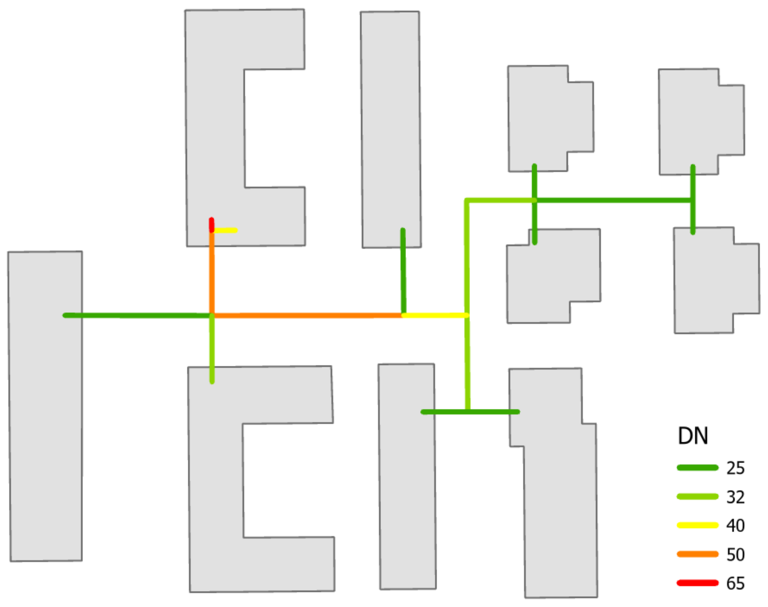
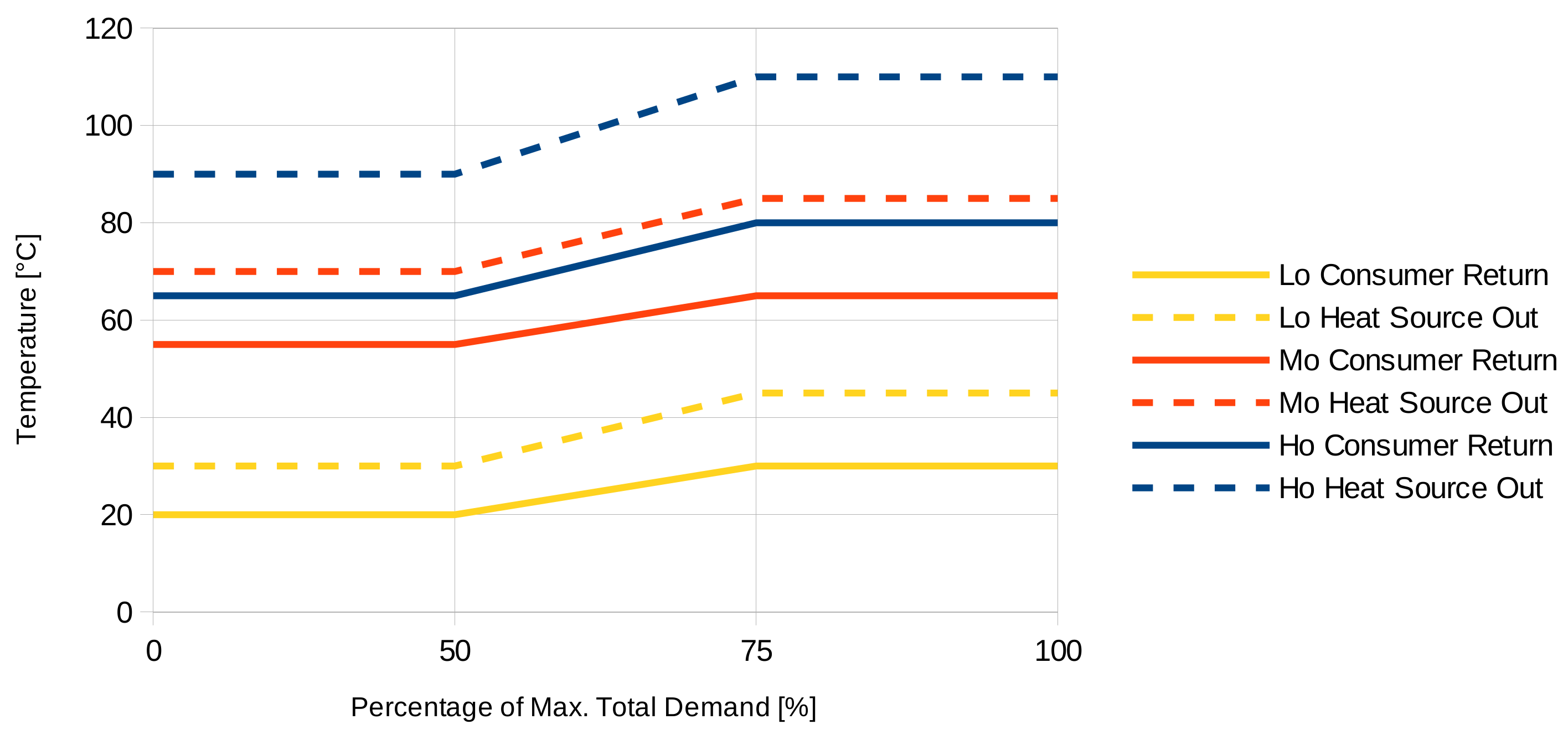
A testing network was created and is described in Table A1 and Figure 4. It consisted of 1 heat source, 10 consumers, 18 pipe sections, each consisting of a supply and a return pipe, and the resulting splitters, mergers, and valves, resulting in a total of 73 components, 82 connections, and 365 equations. For this, a low-, mid-, and high-temperature project folder was created, for each of which a slightly adapted time series file is given, providing synthetic but plausible consumer demand data for a 1 year time range divided into 1 hour frames (see Table A3 for an example showing the demand of the high-temperature test case and Appendix B for further information). Below, Lo, Mo, and Ho stand for low-, medium-, and high-temperature levels set as shown in Figure 5. For each, numbers from 1 to 3 indicate insulation strength, with three settings per temperature level. Each of these nine settings was set in the settings.csv files (see Table A2). Results are compared with the validation calculations from Section 2.
In the test cases described above, DiGriPy was used with a minimal consumer demand of 10 W, such that minimal heat loss in times of no heat demand was taken into account. This reflects the way in which validation calculations are performed, as Equation (5) also leads to minimal values that do not equal zero. This also improved simulation stability.
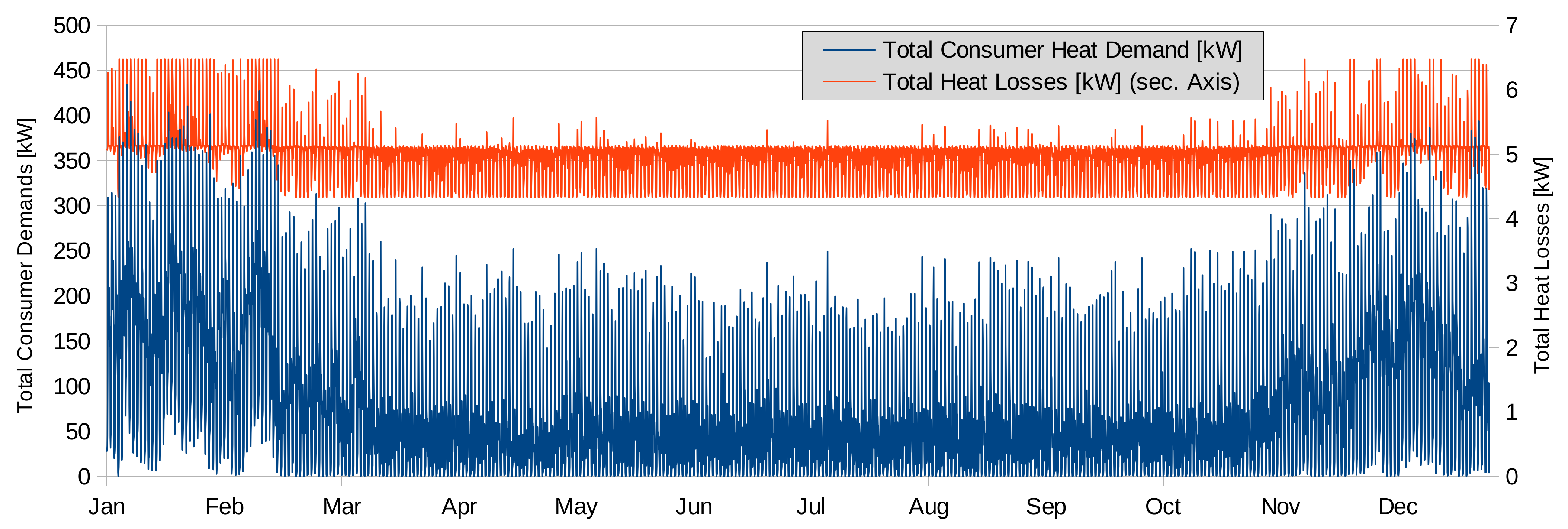
Figure 6 and Figure 7 show the consumer demands and resulting network heat losses for the 1 year time series and in a 4 day extract. Heat losses of the network sensibly followed the consumers’ demands, where peaks in demand led to peaks in the losses graph, while losses did not fall under a certain value, which was about 4.3 kW in the high-temperature case. Even when consumer demand of zero was defined in the time series, there was mass flow in all pipes, and system ensured that the consumer return temperature was guaranteed. As this was 60 ° C while the heat-source supply temperature was 90 ° C in the plotted high-temperature test case, losses were still quite high despite a minimal demand of 100 W. Mass flow is determined depending on the guaranteed temperature at the heat exchangers of the consumers and their heat demand. However, since the mass of water in the system is constant, heat losses cannot become zero given the temperature difference between water in the pipe and ground temperature. The comparison of the test-case results for different temperature levels is displayed in Figure 8, clearly showing this correlation.
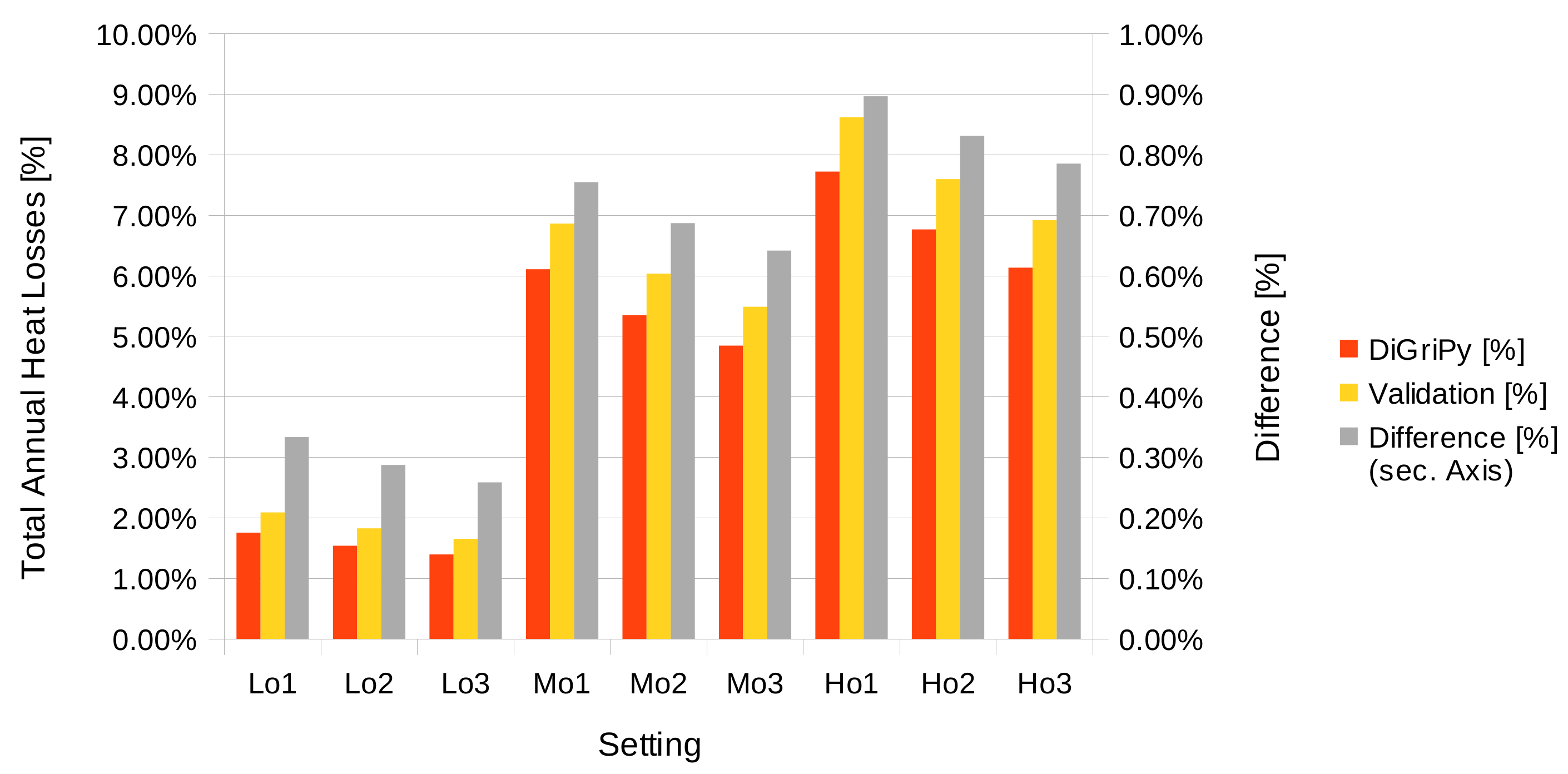
Figure 9 shows the comparison of the DiGriPy calculations and the validation calculations described in Section 2. While deviations were in the range of about 0.26–0.9%, the graphic also shows that the deviations were higher with lower insulation levels and higher temperatures because the difference in how minimal heat losses at times of no demand was considered. For the validation calculations, heat loss was directly proportional to temperature, as shown in Equation (5), and thereby higher in the high-temperature case. In DiGriPy, a minimal consumer demand of 10 W was defined for all test scenario settings, i.e., for all temperature levels. This value was more significant for the low-temperature case than it is for the high-temperature case, as overall heat fluxes were lower. Thus, heat loss at times of no demand was larger with higher temperatures in the validation calculations, while it was more significant at low temperatures in DiGriPy.

5. Conclusions and Outlook

DiGriPy is a tool that allows for a user to easily simulate a district heating network with only few assumptions. It is capable of building a network from a .csv file that only needs little information on the pipes in the network. Time-series files are used to perform simulations over arbitrary numbers of time steps while functioning well and stably. Different control parameters can simply be set in a common settings file, making a comparison of the results fast and easy, as it is performed and automatically displayed in postprocessing.
The results for various scenarios of a test case were compared to calculations on the basis of measured specific heat losses of certain pipes. Overall agreement was very good, and the main differences can be explained by the distinct ways in which minimal demand values were used instead of zero demand.
Further development of the tool is the implementation of decentralized solar-thermal-heat generation that feeds into the grid. One idea is to define this as a consumer object providing heat by negative-demand time series. Another task is to extend the network control options to realistically represent low- and no-demand situations. In the long run, it would be interesting to include heat storage, but that most likely requires deeper changes in the way in which the simulation process works in DiGriPy. While storage needs the time frames to be dependent to one another, the usage of heat storage is also always coupled to control strategies, which can depend on different aims, such as reduced emissions or lowest heat prices, which might contradict each other.

Author Contributions

Conceptualization: L.V.; methodology: L.V. and J.B.; software: J.B.; validation: L.V. and J.B.; writing—original draft and review: L.V. and J.B.; Writing—Editing: L.V. All authors have read and agreed to the published version of the manuscript.

Funding

This research was funded by the Federal Ministry for Economic Affairs and Energy (BMWi) and the Federal Ministry of Education and Research (BMBF) of Germany in the project ENaQ (project number 03SBE111).

Data Availability Statement

The software and data presented in this study are openly available in https://github.com/lvorspel/DiGriPy at https://www.doi.org/10.5281/zenodo.4956223.

Acknowledgments

The authors thank Francesco Witte, who adopted all the necessary changes in TESPy and was open to discussion. We also thank Patrik Schönefeld, who created the hot-water and electricity demand time series within the ENaQ project that were used for the test case.

Conflicts of Interest

The authors declare no conflict of interest.

Abbreviations

The following abbreviations are used in this manuscript:
CPUCentral processing unit
CUDACompute Unified Device Architecture
DiGriPyDistrict heating grid simulation in Python
DNNominal diameter
GPUGraphics processing unit
PJPPlastic jacket pipe
TESPyThermal engineering systems in Python

Appendix A. Input Files

Table A1. The network.csv file representing the test network as displayed in Figure 4. An explanation on how to create the file can be found in Section 3.1.
pipe_IDprior_IDPassageDNShape_Length
100652.2
211404.8
3105017.3
4312529.8
5303213.5
6315039.0
7612517.4
8604012.9
9813219.6
1091259.1
11912510.1
12813223.4
131213213.8
14131257.0
15131258.7
161302532.2
17161256.9
18161256.6
Table A2. The settings.csv file used in test cases described in Section 4.
p_pump_lowp_pump_hight_source_upper_limitt_source_lower_limit
444530
444530
444530
448570
448570
448570
4411090
4411090
4411090
t_consumer_return_hight_consumer_return_lowend_high_tbegin_low_t
30207550
30207550
30207550
65557550
65557550
65557550
80657550
80657550
80657550
min_consumer_demandpr_at_largest_consumersimulate_couplingsinsulation_level
100.602
100.601
100.603
100.602
100.601
100.603
100.602
100.601
100.603
pipe_typelambda_inslambda_soildepthdistactivet_ambname
KMR0.031.20.60.2110Lo2
KMR0.031.20.60.2110Lo1
KMR0.031.20.60.2110Lo3
KMR0.031.20.60.2110Mo2
KMR0.031.20.60.2110Mo1
KMR0.031.20.60.2110Mo3
KMR0.031.20.60.2110Ho2
KMR0.031.20.60.2110Ho1
KMR0.031.20.60.2110Ho3
Table A3. Excerpt of demands.csv file of Ho test cases described in Section 4.
Time2457101114151618
01/01/17 01:00 AM3634.76391.62986.81732.42623.07098.51448.71891.1833.52234.5
01/01/17 02:00 AM2346.06216.92578.12248.32258.26430.21442.21683.31411.71443.1
01/01/17 03:00 AM2864.46232.63960.52368.72422.06795.01592.41850.81526.51657.3
01/01/17 04:00 AM4862.26256.73443.52558.62577.97075.21660.01990.21669.71629.0
01/01/17 05:00 AM5889.27730.36326.42573.65440.67902.61975.72963.41999.51970.9
01/01/17 06:00 AM31,325.27046.117,457.511,227.08434.48988.87793.34700.55170.110,969.9
01/01/17 07:00 AM77,672.510,031.229,836.511,565.417,738.617,830.69464.313,320.410,278.310,664.6
01/01/17 08:00 AM95,699.817,595.944,943.222,176.722,637.831,177.815,069.232,609.813,061.314,132.0
01/01/17 09:00 AM68,068.122,895.246,983.920,501.820,355.543,895.95963.215,744.69576.83784.8
01/01/17 10:00 AM65,973.516,915.827,033.822,125.918,156.749,277.56850.318,321.95926.87823.5
01/01/17 11:00 AM53,736.018,535.040,660.114,044.218,727.242,053.212,891.718,813.611,365.912,756.8

Appendix B. Demand Time Series

The demand time series used in the test case are also provided in the repository. Space-heating demand was simulated with QuaSi [20], and hot-water demand and electricity demand were simulated using LoadProfileGenerator [21]. To determine the heating demand of one building, the space-heating and hot-water demands were each considered as loads, and electricity demand as internal gains. The test case was loosely defined on the planned district in the ENaQ project (information about the project can be found in Wehkamp et al. [17]), but the amount and position of buildings were altered. Therefore, the design of the heating grid was also adjusted.

References

  1. The Paris Agreement. 2015. Available online: https://unfccc.int/process-and-meetings/the-paris-agreement/the-paris-agreement (accessed on 22 January 2021).
  2. Zeitreihen zur Entwicklung der Erneuerbaren Energien in Deutschland. February 2021. Available online: https://www.erneuerbare-energien.de/EE/Navigation/DE/Service/Erneuerbare_Energien_in_Zahlen/Zeitreihen/zeitreihen.html (accessed on 27 May 2021).
  3. European Union’s Horizon 2020 Research and Innovation Programme under Grant Agreement No. 695989. Available online: https://heatroadmap.eu/ (accessed on 30 May 2021).
  4. Profiles and Baselines for Heating and Cooling Energy Demands in 2015 for EU28 Countries. Available online: https://heatroadmap.eu/heating-and-cooling-energy-demand-profiles/ (accessed on 30 May 2021).
  5. Paardekooper, S.; Lund, R.; Mathiesen, B.; Chang, M.; Petersen, U.; Grundahl, L.; David, A.; Dahlbæk, J.; Kapetanakis, I.; Lund, H.; et al. Heat Roadmap Europe 4: Quantifying the Impact of Low-Carbon Heating and Cooling Roadmaps; Aalborg Universitetsforlag: Aalborg, Denmark, 2018. [Google Scholar]
  6. Ifeu-Institut, GEF Ingenieur AG and AGFW. Transformationsstrategie Fernwärme; AGFW|Der Energieeffizienzverband für Wärme, Kälte und KWK e.V.: Frankfurt am Main, Germany, 2013. [Google Scholar]
  7. Kobiela, G.; Samadi, S.; Kurwan, J.; Tönjes, A.; Fischedick, M.; Koska, T.; Lechtenböhmer, S.; März, S.; Schüwer, D. CO2-Neutral bis 2035: Eckpunkte eines deutschen Beitrags zur Einhaltung der 1,5-°C-Grenze. In Diskussionsbeitrag für Fridays for Future Deutschland; Technical Report; Wuppertal Institut für Klima, Umwelt, Energie: Wuppertal, Germany, 2020. [Google Scholar]
  8. Deutsche Energie-Agentur (dena); Allianz für Gebäude-Energie-Effizienz (geea). Szenarien für Eine Marktwirtschaftliche Klima- und Ressourcenschutzpolitik 2050 im Gebäudesektor. Final Report, Dena. 2017. Available online: https://www.dena.de/fileadmin/dena/Dokumente/Pdf/9220_Gebaeudestudie_Szenarien_Klima-_und_Ressourcenschutzpolitik_2050.pdf (accessed on 25 January 2021).
  9. Franco, A. Methods for the Sustainable Design of Solar Energy Systems for Industrial Process Heat. Sustainability 2020, 12, 5127. [Google Scholar] [CrossRef]
  10. Absatzentwicklung Wärmepumpen in Deutschland von 2012–2020. Available online: https://www.waermepumpe.de/presse/zahlen-daten/?tx_yag_pi1%5Bcontroller%5D=ItemList#yag_646 (accessed on 29 January 2021).
  11. Pehnt, M.; Nast, M.; Götz, C.; Blömer, S.; Barckhausen, A.; Schröder, D.; Miljes, R.; Pottbäcker, C.; Breier, H.; Nabe, C.; et al. Innovative Modellvorhaben Wärmenetzsysteme 4.0. Final Report, Ifeu, Adelphi, Ecofys, PwC, Dena, AEE. 2017. Available online: https://www.ifeu.de/fileadmin/uploads/Wärmenetze-4.0-Endbericht-final.pdf (accessed on 18 December 2019).
  12. ROKA3. Available online: https://www.roka3.de/ (accessed on 29 May 2021).
  13. NEPLAN Heating/Cooling. Available online: https://www.neplan.ch/neplanproduct/gas-water-heating-4/ (accessed on 29 May 2021).
  14. THERMOS-Thermal Energy Resource Modelling and Optimisation System. 2019. Available online: https://www.thermos-project.eu/home/ (accessed on 25 November 2019).
  15. DHNx. 2020. Available online: https://github.com/oemof/DHNx (accessed on 29 May 2021).
  16. Röder, J.; Meyer, B.; Krien, U.; Zimmermann, J.; Stührmann, T.; Zondervan, E. Optimal Design of District Heating Networks with Distributed Thermal Energy Storages–Method and Case Study. Int. J. Sustain. Energy Plan. Manag. 2021, 31, 5–22. [Google Scholar] [CrossRef]
  17. Wehkamp, S.; Schmeling, L.; Vorspel, L.; Roelcke, F.; Windmeier, K.L. District Energy Systems: Challenges and New Tools for Planning and Evaluation. Energies 2020, 13, 2967. [Google Scholar] [CrossRef]
  18. Nussbaumer, T.; Thalmann, S.; Jenni, A.; Ködel, J. Planungshandbuch Fernwärme; EnergieSchweiz: Ittigen, Switzerland, 2017; ISBN 3-90870505-30-4. [Google Scholar]
  19. Witte, F.; Tuschy, I. TESPy: Thermal Engineering Systems in Python. J. Open Source Softw. 2020, 5, 2178. [Google Scholar] [CrossRef]
  20. Generische Gebäudesimulation als Bestandteil der Quartier-Simulationssoftware “QuaSi”-Verbundvorhaben EnStadtEs-West: Klimaneutrales Stadtquartier Neue Weststadt Esslingen; Technical University of Braunschweig-IGS and Steinbeis-Innovationszentrum Energieplus: Braunschweig, Germany, 2020.
  21. Pflugradt, N.; Muntwyler, U. Synthesizing residential load profiles using behavior simulation. Energy Procedia 2017, 122, 655–660. [Google Scholar] [CrossRef]
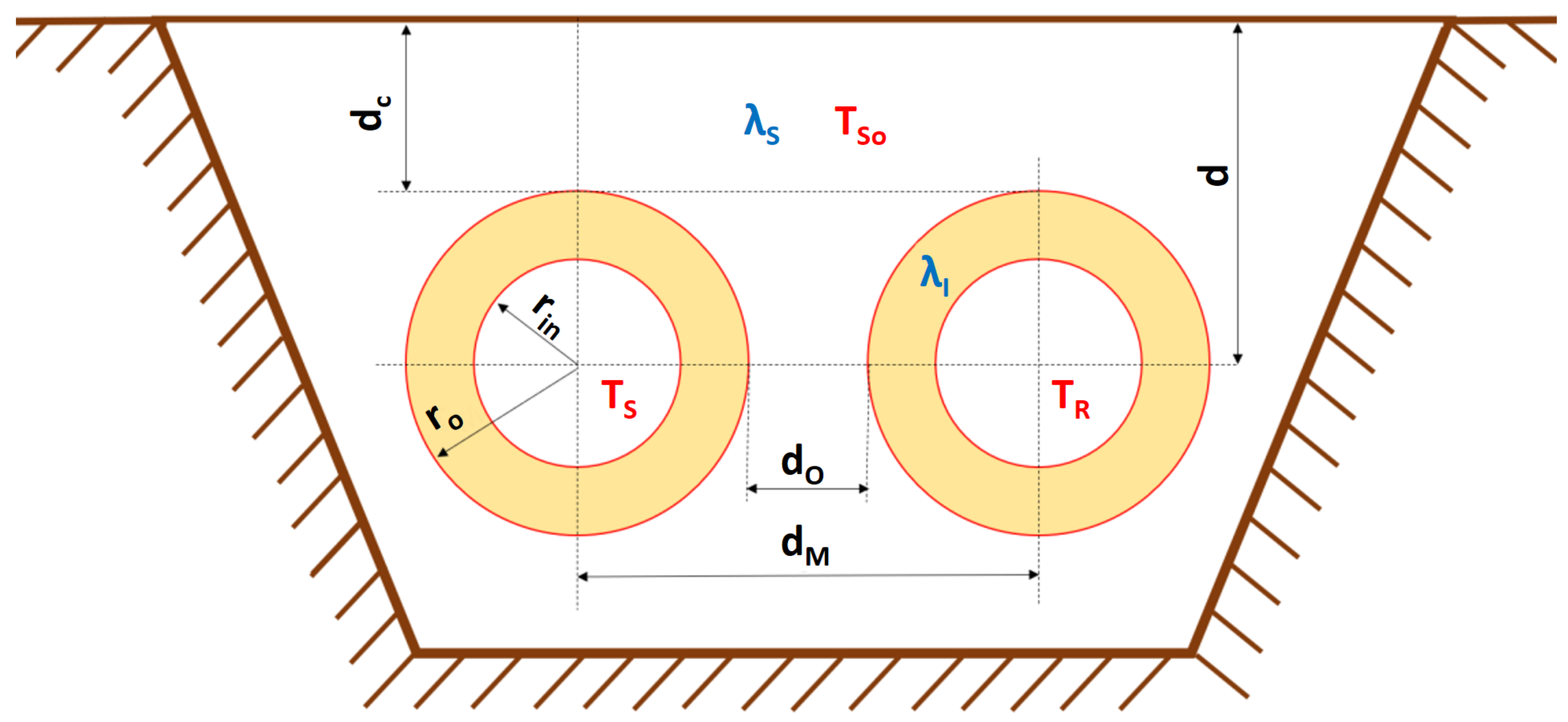
Figure 1. Scheme of two underground district heating pipes. Definitions are based on Nussbaumer et al. [18].
Computation 09 00072 g001
Figure 2. Pump pressure, heat-source temperature, and consumer return temperature set in respect to ratio of system’s current heat demand and maximal heat demand in one frame. Parameters can be set in settings.csv.
Computation 09 00072 g002
Figure 3. Runtime for 100 frames of three high-temperature settings with features of using CUDA and multiprocessing consecutively turned on and off.
Computation 09 00072 g003
Figure 4. Exemplary map of a heat grid with 10 consumers, 1 heat source (HS), and 18 pipes. This translates to the network.csv file shown in Table A1.
Computation 09 00072 g004
Figure 5. Given temperature values in test scenarios using high- (Ho), medium- (Mo), and low- (Lo) temperature setting.
Computation 09 00072 g005
Figure 6. Total demanded heat source and resulting heat losses in high-temperature test case.
Computation 09 00072 g006
Figure 7. Heat-source demand results and total consumer demands in high-temperature test case—January days. Heat losses on secondary axis.
Computation 09 00072 g007
Figure 8. Comparison of heat losses in different test cases.
Computation 09 00072 g008
Figure 9. Comparison of DiGriPy heat losses as fraction of total heat-source demands with results of validation calculations as explained in Section 2. Difference in results is plotted against the secondary axis.
Computation 09 00072 g009
Publisher’s Note: MDPI stays neutral with regard to jurisdictional claims in published maps and institutional affiliations.