Designing of Parking Spaces on Parking Taking into Account the Parameters of Design Vehicles


Abstract
1. Introduction
2. Description of the Research Problem
3. Theoretical Part
4. Materials and Methods
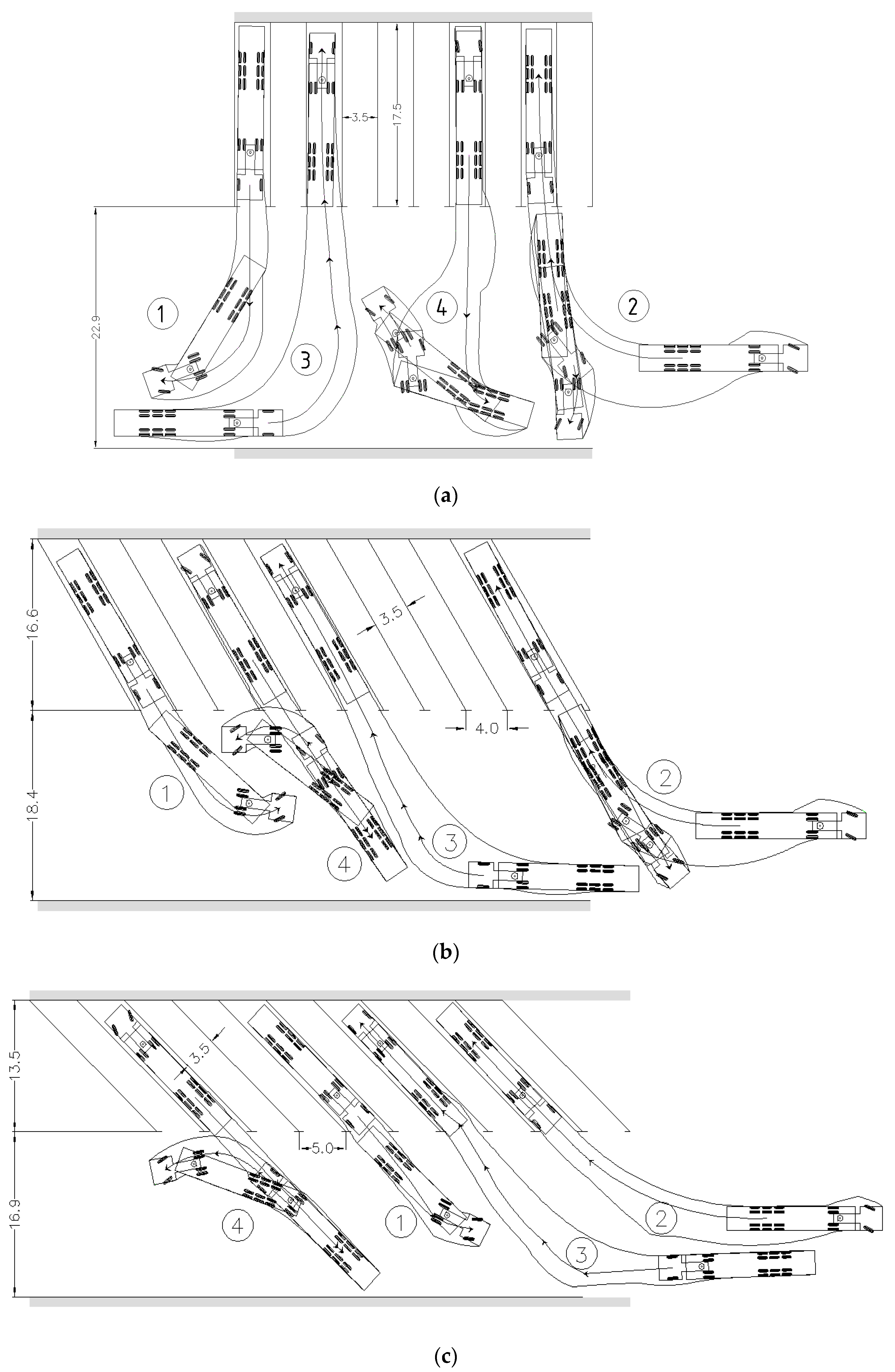
- The road train leaves the parking place in the forward direction;
- The road train drives backwards in a parking place;
- The road train drives forward in a parking place;
- The road train leaves the parking place in reverse.
5. Results
6. Conclusions
Author Contributions
Funding
Conflicts of Interest
References
- Highway Research Board. Parking Principles; Special Report 125; Highway Research Board: Washington, DC, USA, 1971; p. 217. [Google Scholar]
- Homburger, W.S. Transportation and Traffic Engineering Handbook; Prentice-Hall: Upper Saddle River, NJ, USA, 1982; p. 883. [Google Scholar]
- Young, W. Parking principles: Some thoughts on the design of parking lots. Aust. Road Res. 1987, 17, 132–136. [Google Scholar]
- Westin, R.B.; Gillen, D.W. Parking location and transit demand: A case study of endogenous attributes in disaggregate mode choice models. J. Econ. 1978, 8, 75–101. [Google Scholar] [CrossRef]
- Calthrop, E.; Proost, S. Regulating on-street parking. Reg. Sci. Urban Econ. 2006, 36, 29–48. [Google Scholar] [CrossRef]
- Glazer, A.; Niskanen, E. Parking fees and congestion. Reg. Sci. Urban Econ. 1992, 22, 123–132. [Google Scholar] [CrossRef]
- Khordagui, N. Parking prices and the decision to drive to work: Evidence from California. Transp. Res. Part A Policy Pract. 2019, 130, 479–495. [Google Scholar] [CrossRef]
- Higgins, T.J. Parking taxes: Effectiveness, legality and implementation, some general considerations. Transportation 1992, 19, 221–230. [Google Scholar] [CrossRef]
- Shoup, D.C. The high cost of free parking. J. Plan. Educ. Res. 2005, 17, 3–20. [Google Scholar] [CrossRef]
- Gillen, D.W. Parking policy, parking location decisions and the distribution of congestion. Transportation 1978, 7, 69–85. [Google Scholar] [CrossRef]
- Waraich, R.A.; Axhausen, K.W. Agent-based parking choice model. Transp. Res. Rec. 2012, 2319, 39–46. [Google Scholar] [CrossRef]
- Callejas-Cuervo, M.; Valero Bustos, H.; Alarcon-Aldana, A. Simulation Based on Systems Dynamics and Intelligent Agents; Editorial Uptc: Tunja, Colombia, 2018; p. 112. ISBN 9789586602679. [Google Scholar]
- Ottomanelli, M.; Dell’Orco, M.; Sassanelli, D. Modelling parking choice behaviour using possibility theory. Transp. Plan. Technol. 2011, 34, 647–667. [Google Scholar] [CrossRef]
- Janak, P.; Pritikana, D.; Sanjaykumar, M.D. Study on demand and characteristics of parking system in urban areas: A review. J. Traffic Transp. Eng. 2020, 7, 111–124. [Google Scholar]
- Arnott, R.; Rowse, J. Modeling parking. J. Urban Econ. 1999, 45, 97–124. [Google Scholar] [CrossRef]
- Christiansen, P.; Engebretsen, O.; Fearnley, N.; Hanssen, J.U. Parking facilities and the built environment: Impacts on travel behaviour. Transp. Res. Part A Policy Pract. 2017, 95, 198–206. [Google Scholar] [CrossRef]
- Inan, M.O.; Inci, E.; Lindsey, C.R. Spillover parking. Transp. Res. Part B Methodol. 2019, 125, 197–228. [Google Scholar] [CrossRef]
- Gonzalez-Gonzales, E.; Nogues, S.; Stead, D. Parking futures: Preparing European cities for the advent of automated vehicles. Land Use Policy 2020, 91, 104010. [Google Scholar] [CrossRef]
- Ngo, H.Q.T.; Nguyen, T.P.; Nguyen, H. Hardware Design for Intelligent IoT Approach to Optimize Parking Slots. In Proceedings of the 13th International Conference on Advanced Computing and Applications, ACOMP 2019, Nha Trang, Vietnam, 26–28 November 2019; pp. 171–175. [Google Scholar]
- Chaudhary, G.; Agrawal, H.; Tirkey, S.; Nath, V. Study and Design of Smart City with Internet of Things: A Review. In Proceedings of the 4th International Conference on Nanoelectronics, Circuits and Communication Systems, NCCS 2018, Ranchi, India, 3–4 November 2018; Lecture Notes in Electrical Engineering 2020. Volume 642, pp. 533–545. [Google Scholar]
- Silva, B.N.; Khan, M.; Han, K. Towards sustainable smart cities: A review of trends, architectures, components, and open challenges in smart cities. Sustain. Cities Soc. 2018, 38, 697–713. [Google Scholar] [CrossRef]
- Jagelcak, J.; Kiktova, M.; Francak, M. The analysis of manoeuvrability of semi-trailer vehicle combination. In LOGI 2019—Horizons of Autonomous Mobility in Europe; Elsevier: Amsterdam, The Netherlands, 2020; pp. 176–181. [Google Scholar]
- Information and Legal Portal Garant Web Site. Available online: http://www.garant.ru/hotlaw/moscow/430F367 (accessed on 27 January 2018).
- Buranov, I. Mayor shifted the burden of responsibility to the region. Newspaper Kommersant, 16 June 2012; Volume 218, 5003. [Google Scholar]
- The Ministry of Internal Affairs of Russia. Monitoring Compliance with the Norms, Rules and Standards when Designation and Construction of Roadside Facilities (Service Facilities); Methodical Recommendations; SIC STSI of the Ministry of Internal Affairs of Russia: Moscow, Russia, 2004; p. 28. [Google Scholar]
- Rankin, V.U. Automobile transportations and the organization of traffic. Transport 1981, 592. [Google Scholar]
- ABaerwald, J.E. Transportation and Traffic Engineering Handbook, 3rd ed.; Institute of Traffic Engineers: Washington, DC, USA, 1965; p. 717. [Google Scholar]
- Design and Equipment of Highways to Ensure Traffic Safety. Methodical Recommendations. Transport 1983.
- Regulations for the Placement of Multifunctional Road Zones of the Service on the Highways of the State Company “Russian Highways” (Approved by the Order of the State Company “Russian Highways” 24 June 2013, No. 114). Available online: http://www.rhighways.ru/for_investor/road_service/multifunctionalroad_service_area (accessed on 12 August 2018).
- Pospelov, P.I.; Schit, B.A.; Abdunazarov, J.N. Designing of parking spaces on car parking. Sci. Eng. Roads 2016, 2, 6–10. [Google Scholar]
- Iranpour, R.; Tung, D. Methodology for optimal design of a parking lot. Most land-use projects, factories, profess. J. Transp. Eng. 1989, 115, 139–160. [Google Scholar] [CrossRef]
- Young, W. A review of parking lot design models. Transp. Rev. 2007, 8, 161–181. [Google Scholar] [CrossRef]
- Leephakpreeda, T. Car-parking guidance with fuzzy knowledge-based decision making. Build. Environ. 2007, 42, 803–809. [Google Scholar] [CrossRef]
- Maulana, M.F.; Adhy, S.; Bahtiar, N.; Waspada, I. Development of a smart parking system based on internet of things using object-oriented analysis and design method. J. Phys. 2020, 1524. [Google Scholar] [CrossRef]
- AutoTURN. Advanced Vehicle Simulations. Available online: http://store.softline.ru/transoft/transoft-autoturn (accessed on 18 September 2018).
- Help for Guests. Guidelines. Available online: http://www.gosthelp.ru (accessed on 18 September 2018).
- Ministry of International Affairs of Russia. The Methodical Recommendations on Designing and Equipping the Highways for Road Safety; Ministry of International Affairs of Russia: Moscow, Russia, 1983. [Google Scholar]
- Abnunazarov, J.; Mikusova, M. Testing trajectory of road trains with program complexes. Arch. Automot. Eng. Arch. Motoryz. 2019, 83, 103–112. [Google Scholar] [CrossRef]
- Mikusova, M.; Abnunazarov, J. Modelling of vehicles movements for the design of parking spaces. In Proceedings of the International Conference on Computational Collective Intelligence (ICCCI), Hendaye, France, 4–6 September 2019. Part II, LNCS 11684, in press. [Google Scholar]
- Abdunazarov, J.N. Justification of the parameters design vehicle. In Collection of Materials of the III All-Russian Road Congress; Publishing House NGTU: Moscow, Russia, 2013; pp. 122–131. [Google Scholar]
- Abdunazarov, J.N. Modeling of the movement of the design vehicles on parking space. Sci. Eng. Roads 2018, 84, 10–11. [Google Scholar]
- Abdunazarov, J.N.; Mamarasulova, M.N. Recommended parameters of design vehicles for the Russian Federation. Young Sci. 2016, 7.2, 26–28. [Google Scholar]


| Type of Design Vehicles | Designation | Wheelbase (m) | Dimension (m) | ||||
|---|---|---|---|---|---|---|---|
| General | Overhang | ||||||
| RD (1) | TR (2) | Length | Width | Front | Rear | ||
| Passenger Car | P | M1 | 2.90 | 4.90 | 1.90 | 0.90 | 1.10 |
| City Bus | CB | M2 | 6.20 | 12.0 | 2.50 | 2.75 | 3.05 |
| Bus | B | M3 | 6.90/1.30 | 15.0 | 2.50 | 2.60 | 4.20 |
| Articulated Bus | AB | M3 | 5.96/6.05 | 18.4 | 2.55 | 2.68 | 3.71 |
| Truck | T | N3 | 6.80 | 12.0 | 2.50 | 1.50 | 3.70 |
| Road Train | A16 | N3 + O4 | 3.80/7.02 | 16.50 | 2.50 | 1.43 | 2.98 |
| Road Train | A20 | N3 + O4 | 6.80/4.30 | 19.80 | 2.50 | 1.50 | 0.70 |
| Type of Design Vehicles | Minimum Turning Radius (m) | Minimum Outer Radius (m) | Minimum Inner Radius (m) |
|---|---|---|---|
| Passenger Car (P) | 6.55 | 6.85 | 4.42 |
| City Bus (C) | 9.20 | 10.54 | 5.40 |
| Bus (B) | 10.32 | 11.52 | 6.40 |
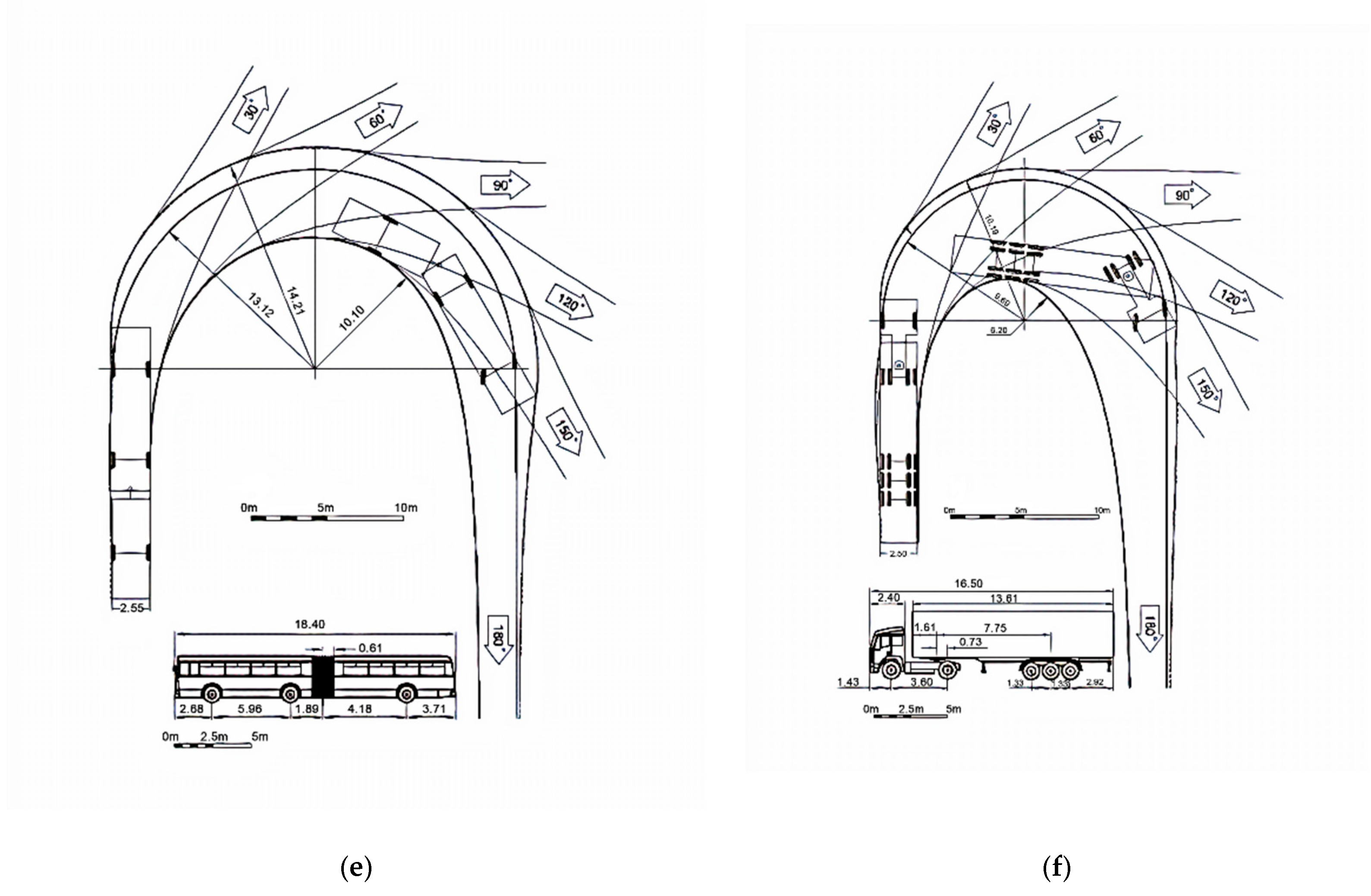
| Articulated Bus (A) | 13.12 | 14.21 | 10.10 |
| Truck (T) | 11.07 | 11.82 | 6.15 |
| Road Train (A16) | 9.69 | 10.19 | 6.20 |
| Road Train (A20) | 12.06 | 12.63 | 8.50 |
| Vehicle Installation Angle (Degree) | Sizes of Elements (m) | Average Area for 1 Vehicle (m2) | |||||||||
|---|---|---|---|---|---|---|---|---|---|---|---|
| A | B | C | D | E | F | G | H | I | without | with | |
| Manoeuvring | |||||||||||
| 1 | 2 | 3 | 4 | 5 | 6 | 7 | 8 | 9 | 10 | 11 | 12 |
| One-way car parking (P) | |||||||||||
| 90 | 5.0 | 7.0 | 17.0 | 11.5 | 0.5 | 6.0 | 2.5 | 2.5 | 0.5 | 12.5 | 28.7 |
| 60 | 5.2 | 4.2 | 14.6 | 8.9 | 0.5 | 3.2 | 2.5 | 2.9 | 0.5 | 15.1 | 25.8 |
| 45 | 4.8 | 4.0 | 13.6 | 8.3 | 0.5 | 3.0 | 2.5 | 3.5 | 0.5 | 16.8 | 29.0 |
| Two-way car parking (P) | |||||||||||
| 90 | 5.0 | 8.0 | 18.0 | 12.5 | 0.5 | 7.0 | 2.5 | 2.5 | 0.5 | 12.5 | 22.5 |
| 60 | 5.2 | 5.2 | 15.6 | 9.9 | 0.5 | 4.2 | 2.5 | 2.9 | 0.5 | 15.1 | 22.6 |
| 45 | 4.8 | 5.0 | 14.6 | 9.3 | 0.5 | 4.0 | 2.5 | 3.5 | 0.5 | 16.8 | 25.5 |
| Truck parking (T) | |||||||||||
| 90 | 13.0 | 16.1 | 42.1 | 28.6 | 0.5 | 15.1 | 3.5 | 3.5 | 0.5 | 45.5 | 100.1 |
| 60 | 11.8 | 12.4 | 36.0 | 23.7 | 0.5 | 11.4 | 3.5 | 4.0 | 0.5 | 47.2 | 94.8 |
| 45 | 10.5 | 8.7 | 29.7 | 18.7 | 0.5 | 7.7 | 3.5 | 5.0 | 0.5 | 52.5 | 93.5 |
| City bus parking (CB) | |||||||||||
| 90 | 13.0 | 16.1 | 42.1 | 28.6 | 0.5 | 15.1 | 3.5 | 3.5 | 0.5 | 45.5 | 100.1 |
| 60 | 11.8 | 12.4 | 36.0 | 23.7 | 0.5 | 11.4 | 3.5 | 4.0 | 0.5 | 47.2 | 94.8 |
| 45 | 10.5 | 8.7 | 29.7 | 18.7 | 0.5 | 7.7 | 3.5 | 5.0 | 0.5 | 52.5 | 93.5 |
| Bus parking (B) | |||||||||||
| 90 | 16.0 | 19.0 | 51.0 | 34.5 | 0.5 | 18.0 | 3.5 | 3.5 | 0.5 | 56.0 | 120.7 |
| 60 | 14.3 | 16.1 | 44.7 | 29.9 | 0.5 | 15.1 | 3.5 | 4.0 | 0.5 | 57.2 | 119.6 |
| 45 | 12.4 | 11.7 | 36.5 | 23.6 | 0.5 | 10.7 | 3.5 | 5.0 | 0.5 | 62.0 | 118.0 |
| Articulated bus parking (AB) | |||||||||||
| 90 | 19.5 | 25.1 | 64.1 | 44.1 | 0.5 | 24.1 | 3.5 | 3.5 | 0.5 | 68.3 | 154.3 |
| 60 | 17.3 | 20.3 | 54.9 | 37.1 | 0.5 | 19.3 | 3.5 | 4.0 | 0.5 | 69.2 | 148.4 |
| 45 | 14.9 | 18.5 | 48.3 | 32.9 | 0.5 | 17.5 | 3.5 | 5.0 | 0.5 | 74.5 | 164.5 |
| Road train parking (A16) | |||||||||||
| 90 | 17.5 | 23.9 | 58.9 | 40.9 | 0.5 | 22.9 | 3.5 | 3.5 | 0.5 | 61.3 | 143.1 |
| 60 | 16.6 | 18.9 | 52.1 | 35.0 | 0.5 | 17.9 | 3.5 | 4.0 | 0.5 | 66.4 | 140.0 |
| 45 | 13.5 | 17.4 | 44.4 | 30.4 | 0.5 | 16.4 | 3.5 | 5.0 | 0.5 | 67.5 | 152.0 |
| Road train parking (A20) | |||||||||||
| 90 | 21.0 | 33.0 | 75.0 | 53.5 | 0.5 | 32.0 | 3.5 | 3.5 | 0.5 | 73.5 | 187.2 |
| 60 | 18.6 | 23.8 | 61.0 | 41.9 | 0.5 | 22.8 | 3.5 | 4.0 | 0.5 | 74.4 | 167.6 |
| 45 | 16.0 | 21.1 | 53.1 | 36.6 | 0.5 | 20.1 | 3.5 | 5.0 | 0.5 | 80.0 | 183.0 |
| Design Vehicle | Passenger Car (P) | Truck (T) | Buses | Road Train | |||
|---|---|---|---|---|---|---|---|
| (CB) | (B) | (AB) | (A16) | (A20) | |||
| Parking space length (m) | 6.0 | 14.0 | 14.0 | 17.0 | 22.5 | 20.0 | 24.0 |
| Set Angle (Degree) | Sizes of Parking Spaces (m) (See Figure 9) | ||||
|---|---|---|---|---|---|
| Ø | α | β | B | C | D |
| A 16 | |||||
| 30 | 30 | 30 | 7.5 | 12.0 | 7.5 |
| 35 | 35 | 35 | 8.5 | 13.0 | 8.5 |
| 40 | 40 | 40 | 8.7 | 13.5 | 8.7 |
| 45 | 45 | 45 | 9.5 | 15.5 | 9.5 |
| A 20 | |||||
| 30 | 30 | 30 | 8.0 | 13.0 | 8.0 |
| 35 | 35 | 35 | 9.0 | 15.5 | 9.0 |
| 40 | 40 | 40 | 9.2 | 16.5 | 9.2 |
| 45 | 45 | 45 | 10.0 | 17.7 | 10.0 |
© 2020 by the authors. Licensee MDPI, Basel, Switzerland. This article is an open access article distributed under the terms and conditions of the Creative Commons Attribution (CC BY) license (http://creativecommons.org/licenses/by/4.0/).
Share and Cite
Mikusova, M.; Abdunazarov, J.; Zukowska, J.; Jagelcak, J. Designing of Parking Spaces on Parking Taking into Account the Parameters of Design Vehicles. Computation 2020, 8, 71. https://doi.org/10.3390/computation8030071
Mikusova M, Abdunazarov J, Zukowska J, Jagelcak J. Designing of Parking Spaces on Parking Taking into Account the Parameters of Design Vehicles. Computation. 2020; 8(3):71. https://doi.org/10.3390/computation8030071
Chicago/Turabian StyleMikusova, Miroslava, Jamshid Abdunazarov, Joanna Zukowska, and Juraj Jagelcak. 2020. "Designing of Parking Spaces on Parking Taking into Account the Parameters of Design Vehicles" Computation 8, no. 3: 71. https://doi.org/10.3390/computation8030071
APA StyleMikusova, M., Abdunazarov, J., Zukowska, J., & Jagelcak, J. (2020). Designing of Parking Spaces on Parking Taking into Account the Parameters of Design Vehicles. Computation, 8(3), 71. https://doi.org/10.3390/computation8030071