An Incompressible Smoothed Particle Hydrodynamics (ISPH) Model of Direct Laser Interference Patterning


Abstract
:1. Introduction
2. Mathematical Model
2.1. Governing Equations
2.2. Non-Dimensionalisation
3. Smoothed Particle Hydrodynamics
3.1. Fundamentals of the SPH Method
3.2. Approximation of Derivatives
3.3. Boundary Conditions
3.4. ISPH Approach
3.5. Time Step Criteria
3.6. Neighbour Search
4. Numerical Solution of Governing Equations
4.1. Discretisation
4.2. Thermal model
4.3. Thermofluiddynamic Model
4.3.1. Discrete ISPH Scheme
4.3.2. Solution of PPE
5. Simulation Results
5.1. Model Parameters
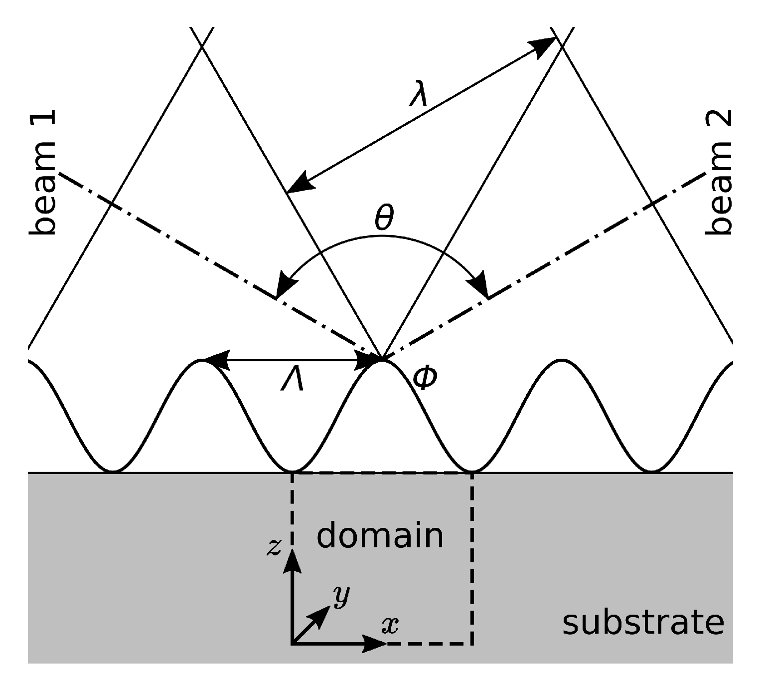
5.2. Numerical Investigation of DLIP
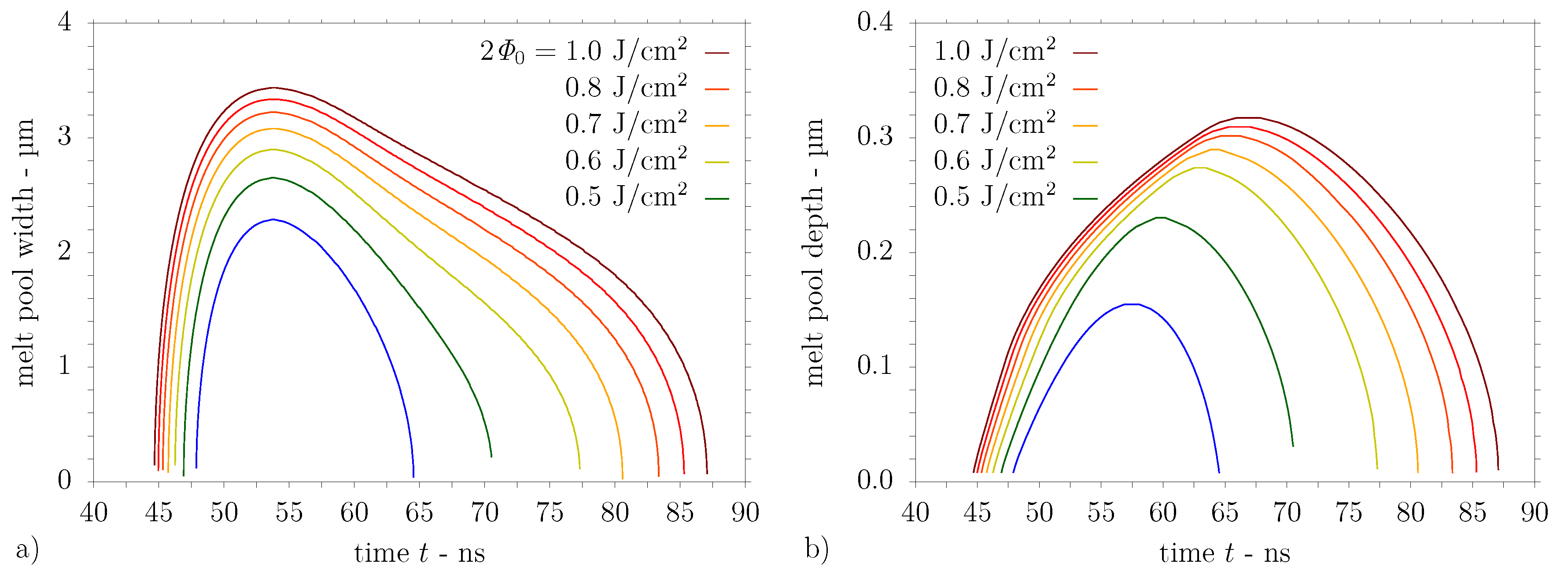
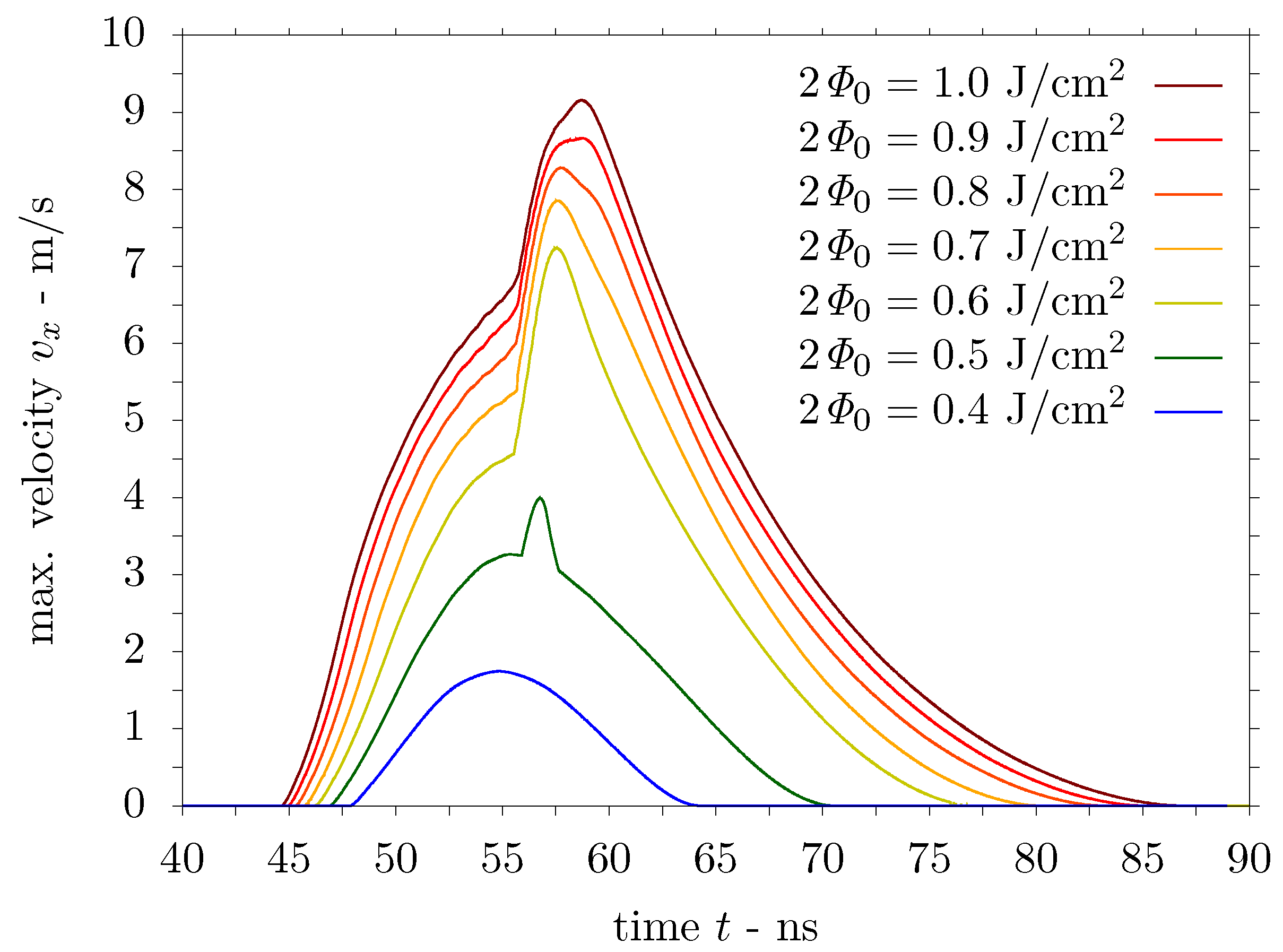
5.2.1. Computational Results for Steel Substrate
5.2.2. Computational Results for Aluminium Substrate
6. Discussion
7. Conclusions
Author Contributions
Funding
Acknowledgments
Conflicts of Interest
Abbreviations
| AISI | American Iron and Steel Institute |
| BiCGStab | biconjugate gradient stabilised |
| CG | conjugate gradient |
| DLIP | direct laser interference patterning |
| FEM | finite element method |
| FWHM | full width at half maximum |
| ISPH | incompressible smoothed particle hydrodynamics |
| PPE | pressure Poisson equation |
| SPH | smoothed particle hydrodynamics |
| WCSPH | weakly compressible smoothed particle hydrodynamics |
References
- Berger, J.; Grosse Holthaus, M.; Pistillo, N.; Roch, T.; Rezwan, K.; Lasagni, A.F. Ultraviolet laser interference patterning of hydroxyapatite surfaces. Appl. Surf. Sci. 2011, 257, 3081–3087. [Google Scholar] [CrossRef]
- Langheinrich, D.; Yslas, E.; Broglia, M.; Rivarola, V.; Acevedo, D.; Lasagni, A. Control of cell growth direction by direct fabrication of periodic micro- and submicrometer arrays on polymers. J. Polym. Sci., Part B Polym. Phys. 2012, 50, 415–422. [Google Scholar] [CrossRef]
- Valle, J.; Burgui, S.; Langheinrich, D.; Gil, C.; Solano, C.; Toledo-Arana, A.; Helbig, R.; Lasagni, A.; Lasa, I. Evaluation of surface microtopography engineered by direct laser interference for bacterial anti-biofouling. Macromol. Biosci. 2015, 15, 1060–1069. [Google Scholar] [CrossRef] [PubMed] [Green Version]
- Müller-Meskamp, L.; Kim, Y.H.; Roch, T.; Hofmann, S.; Scholz, R.; Eckhardt, S.; Leo, K.; Lasagni, A.F. Efficiency enhancement of organic solar cells by fabricating periodic surface textures using direct laser interference patterning. Adv. Mater. 2012, 24, 906–910. [Google Scholar] [CrossRef] [PubMed]
- Roch, T.; Weihnacht, V.; Scheibe, H.J.; Roch, A.; Lasagni, A.F. Direct laser interference patterning of tetrahedral amorphous carbon films for tribological applications. Diamond Relat. Mater. 2013, 33, 20–26. [Google Scholar] [CrossRef]
- Bieda, M.; Schmädicke, C.; Roch, T.; Lasagni, A. Ultra-low friction on 100Cr6-steel surfaces after direct laser interference patterning. Adv. Eng. Mater. 2015, 17, 102–108. [Google Scholar] [CrossRef]
- Estevam-Alves, R.; Günther, D.; Dani, S.; Eckhardt, S.; Roch, T.; Mendonca, C.R.; Cestari, I.N.; Lasagni, A.F. UV direct laser interference patterning of polyurethane substrates as tool for tuning its surface wettability. Appl. Surf. Sci. 2016, 374, 222–228. [Google Scholar] [CrossRef]
- Daniel, C.; Mücklich, F.; Liu, Z. Periodical micro-nano-structuring of metallic surfaces by interfering laser beams. Appl. Surf. Sci. 2003, 208–209, 317–321. [Google Scholar] [CrossRef]
- Dowden, J.M. (Ed.) The Theory of Laser Materials Processing: Heat and Mass Transfer in Modern Technology, 1st ed.; Springer Series in Materials Science; Springer: Dordrecht, The Netherlands, 2009; Volume 119. [Google Scholar] [CrossRef] [Green Version]
- Daniel, C.; Lasagni, A.; Mücklich, F. Stress and texture evolution of Ni/Al multi-film by laser interference irradiation. Surf. Coat. Technol. 2004, 180–181, 478–482. [Google Scholar] [CrossRef]
- Lasagni, A.; Mücklich, F. Study of the multilayer metallic films topography modified by laser interference irradiation. Appl. Surf. Sci. 2005, 240, 214–221. [Google Scholar] [CrossRef]
- Lasagni, A.; D’Alessandria, M.; Giovanelli, R.; Mücklich, F. Advanced design of periodical architectures in bulk metals by means of Laser Interference Metallurgy. Appl. Surf. Sci. 2007, 254, 930–936. [Google Scholar] [CrossRef]
- Lasagni, A.; Mücklich, F. FEM simulation of periodical local heating caused by laser interference metallurgy. J. Mater. Process. Technol. 2009, 209, 202–209. [Google Scholar] [CrossRef]
- Gingold, R.A.; Monaghan, J.J. Smoothed particle hydrodynamics: Theory and application to non-spherical stars. Mon. Not. R. Astron. Soc. 1977, 181, 375–389. [Google Scholar] [CrossRef]
- Lucy, L.B. A numerical approach to the testing of the fission hypothesis. Astron. J. 1977, 82, 1013–1024. [Google Scholar] [CrossRef]
- Marongiu, J.C.; Leboeuf, F.; Caro, J.; Parkinson, E. Free surface flows simulations in Pelton turbines using an hybrid SPH-ALE method. J. Hydraul. Res. 2010, 48, 40–49. [Google Scholar] [CrossRef]
- Pugliese Carratelli, E.; Viccione, G.; Bovolin, V. Free surface flow impact on a vertical wall: A numerical assessment. Theor. Comput. Fluid Dyn. 2016, 30, 403–414. [Google Scholar] [CrossRef]
- Monaghan, J.J. Smoothed particle hydrodynamics and its diverse applications. Annu. Rev. Fluid Mech. 2012, 44, 323–346. [Google Scholar] [CrossRef]
- Violeau, D. Fluid Mechanics and the SPH Method: Theory and Applications; Oxford University Press: Oxford, UK, 2012. [Google Scholar]
- Violeau, D.; Rogers, B.D. Smoothed particle hydrodynamics (SPH) for free-surface flows: Past, present and future. J. Hydraul. Res. 2016, 54, 1–26. [Google Scholar] [CrossRef]
- Shadloo, M.S.; Oger, G.; Le Touzé, D. Smoothed particle hydrodynamics method for fluid flows, towards industrial applications: Motivations, current state, and challenges. Comput. Fluids 2016, 136, 11–34. [Google Scholar] [CrossRef]
- Chen, J.; Beraun, J. Numerical study of ultrashort laser pulse interactions with metal films. Numer. Heat Transf. Part A 2001, 40, 1–20. [Google Scholar]
- Gross, M. Smooth particle hydrodynamics (SPH) modelling of laser cutting. In International Congress on Applications of Lasers & Electro Optics; Laser Institute of America: Orlando, FL, USA, 2008; pp. 637–644. [Google Scholar]
- Muhammad, N.; Rogers, B.D.; Li, L. Understanding the behaviour of pulsed laser dry and wet micromachining processes by multi-phase smoothed particle hydrodynamics (SPH) modelling. J. Phys. D Appl. Phys. 2013, 46, 095101. [Google Scholar] [CrossRef]
- Abidou, D.; Yusoff, N.; Nazri, N.; Awang, M.O.; Hassan, M.A.; Sarhan, A.A. Numerical simulation of metal removal in laser drilling using symmetric smoothed particle hydrodynamics. Precis. Eng. 2017, 49, 69–77. [Google Scholar] [CrossRef]
- Tong, M.; Browne, D.J. Smoothed particle hydrodynamics modelling of the fluid flow and heat transfer in the weld pool during laser spot welding. IOP Conf. Ser. Mater. Sci. Eng. 2012, 27, 012080. [Google Scholar] [CrossRef] [Green Version]
- Hu, H.; Eberhard, P. Thermomechanically coupled conduction mode laser welding simulations using smoothed particle hydrodynamics. Comput. Part. Mech. 2017, 4, 473–486. [Google Scholar] [CrossRef]
- Russell, M.A.; Souto-Iglesias, A.; Zohdi, T.I. Numerical simulation of laser fusion additive manufacturing processes using the SPH method. Comput. Methods Appl. Mech. Eng. 2018, 341, 163–187. [Google Scholar] [CrossRef]
- Yan, Y.; Li, L.; Sezer, K.; Wang, W.; Whitehead, D.; Ji, L.; Bao, Y.; Jiang, Y. CO2 laser underwater machining of deep cavities in alumina. J. Eur. Ceram. Soc. 2011, 31, 2793–2807. [Google Scholar] [CrossRef]
- Hu, H.; Fetzer, F.; Berger, P.; Eberhard, P. Simulation of laser welding using advanced particle methods. GAMM Mitt. Ges. Angew. Math. Mech. 2016, 39, 149–169. [Google Scholar] [CrossRef]
- Tanaka, M.; Cardoso, R.; Bahai, H. Modification of the LSMPS method for the conservation of the thermal energy in laser irradiation processes. Int. J. Numer. Methods Eng. 2019, 117, 161–187. [Google Scholar] [CrossRef]
- Weirather, J.; Rozov, V.; Wille, M.; Schuler, P.; Seidel, C.; Adams, N.A.; Zaeh, M.F. A smoothed particle hydrodynamics model for laser beam melting of Ni-based alloy 718. Comput. Math. Appl. 2019, 78, 2377–2394. [Google Scholar] [CrossRef]
- Liu, S.; Liu, J.; Chen, J.; Liu, X. Influence of surface tension on the molten pool morphology in laser melting. Int. J. Therm. Sci. 2019, 146, 106075. [Google Scholar] [CrossRef]
- Fürstenau, J.P.; Wessels, H.; Weißenfels, C.; Wriggers, P. Generating virtual process maps of SLM using powder-scale SPH simulations. Comput. Part. Mech. 2019, 1–23. [Google Scholar] [CrossRef]
- Demuth, C.; Bieda, M.; Lasagni, A.F.; Mahrle, A.; Wetzig, A.; Beyer, E. Thermal simulation of pulsed direct laser interference patterning of metallic substrates using the smoothed particle hydrodynamics approach. J. Mater. Process. Technol. 2012, 212, 689–699. [Google Scholar] [CrossRef]
- Cao, Y.; Shin, Y.C. Multi-scale modeling of phase explosion in high fluence nanosecond laser ablation and clarification of ablation depth prediction criterion. Appl. Surf. Sci. 2015, 357, 74–85. [Google Scholar] [CrossRef] [Green Version]
- Alshaer, A.W.; Rogers, B.D.; Li, L. Smoothed particle hydrodynamics (SPH) modelling of transient heat transfer in pulsed laser ablation of Al and associated free-surface problems. Comput. Mater. Sci. 2017, 127, 161–179. [Google Scholar] [CrossRef]
- Komen, H.; Shigeta, M.; Tanaka, M. Numerical simulation of molten metal droplet transfer and weld pool convection during gas metal arc welding using incompressible smoothed particle hydrodynamics method. Int. J. Heat Mass Transf. 2018, 121, 978–985. [Google Scholar] [CrossRef]
- Landau, L.D.; Lifshitz, E.M. Fluid Mechanics; Course of Theoretical Physics; Pergamon Press: London, UK, 1959; Volume 6. [Google Scholar]
- Nepomnyashchy, A.; Simanovskii, I.; Legros, J.C. Interfacial convection in Multilayer Systems; Springer: New York, NY, USA, 2006. [Google Scholar]
- Monaghan, J.J.; Lattanzio, J.C. A refined particle method for astrophysical problems. Astron. Astrophys. 1985, 149, 135–143. [Google Scholar]
- Monaghan, J.J. An introduction to SPH. Comput. Phys. Commun. 1988, 48, 89–96. [Google Scholar] [CrossRef]
- Price, D.J. Smoothed particle hydrodynamics and magnetohydrodynamics. J. Comput. Phys. 2012, 231, 759–794. [Google Scholar] [CrossRef] [Green Version]
- Schoenberg, I.J. Contributions to the problem of approximation of equidistant data by analytic functions. Part A. On the problem of smoothing or graduation. A first class of analytic approximation formulae. Q. Appl. Math. 1946, 4, 45–99. [Google Scholar] [CrossRef] [Green Version]
- Morris, J.P.; Fox, P.J.; Zhu, Y. Modeling low Reynolds number incompressible flows using SPH. J. Comput. Phys. 1997, 136, 214–226. [Google Scholar] [CrossRef]
- Speith, R. Untersuchung von Smoothed Particle Hydrodynamics Anhand Astrophysikalischer Beispiele. Ph.D. Thesis, Eberhard Karls Universität Tübingen, Tübingen, Germany, 1998. (In German). [Google Scholar]
- Leroy, A. A New Incompressible SPH Model: Towards Industrial Applications (Un Nouveau modèle SPH Incompressible: Vers L’application à des cas Industriels). Ph.D. Thesis, Université Paris-Est, Paris, France, 2014. [Google Scholar]
- Monaghan, J.J. Smoothed particle hydrodynamics. Annu. Rev. Astron. Astrophys. 1992, 30, 543–574. [Google Scholar] [CrossRef]
- Monaghan, J.J. Smoothed particle hydrodynamics. Rep. Prog. Phys. 2005, 68, 1703–1759. [Google Scholar] [CrossRef]
- Cummins, S.J.; Rudman, M. An SPH projection method. J. Comput. Phys. 1999, 152, 584–607. [Google Scholar] [CrossRef]
- Brookshaw, L. A method of calculating radiative heat diffusion in particle simulations. Proc. Astron. Soc. Aust. 1985, 6, 207–210. [Google Scholar] [CrossRef]
- Cleary, P.W.; Monaghan, J.J. Conduction modelling using smoothed particle hydrodynamics. J. Comput. Phys. 1999, 148, 227–264. [Google Scholar] [CrossRef]
- Randles, P.; Libersky, L.D. Normalized SPH with stress points. Int. J. Numer. Methods Eng. 2000, 48, 1445–1462. [Google Scholar] [CrossRef]
- Randles, P.; Libersky, L.D. Smoothed particle hydrodynamics: Some recent improvements and applications. Comput. Methods Appl. Mech. Eng. 1996, 139, 375–408. [Google Scholar] [CrossRef]
- Libersky, L.D.; Petschek, A.G. Smooth particle hydrodynamics with strength of materials. In Advances in the Free-Lagrange Method Including Contributions on Adaptive Gridding and the Smooth Particle Hydrodynamics Method; Springer: Berlin/Heidelberg, Germany, 1991; pp. 248–257. [Google Scholar]
- Monaghan, J.J. Simulating free surface flows with SPH. J. Comput. Phys. 1994, 110, 399–406. [Google Scholar] [CrossRef]
- Kulasegaram, S.; Bonet, J.; Lewis, R.; Profit, M. A variational formulation based contact algorithm for rigid boundaries in two-dimensional SPH applications. Comput. Mech. 2004, 33, 316–325. [Google Scholar] [CrossRef]
- Shao, S.; Lo, E.Y. Incompressible SPH method for simulating Newtonian and non-Newtonian flows with a free surface. Adv. Water Resour. 2003, 26, 787–800. [Google Scholar] [CrossRef]
- Lee, E.S.; Moulinec, C.; Xu, R.; Violeau, D.; Laurence, D.; Stansby, P. Comparisons of weakly compressible and truly incompressible algorithms for the SPH mesh free particle method. J. Comput. Phys. 2008, 227, 8417–8436. [Google Scholar] [CrossRef]
- Colagrossi, A.; Bouscasse, B.; Antuono, M.; Marrone, S. Particle packing algorithm for SPH schemes. Comput. Phys. Commun. 2012, 183, 1641–1653. [Google Scholar] [CrossRef] [Green Version]
- Molteni, D.; Colagrossi, A. A simple procedure to improve the pressure evaluation in hydrodynamic context using the SPH. Comput. Phys. Commun. 2009, 180, 861–872. [Google Scholar] [CrossRef]
- Antuono, M.; Colagrossi, A.; Marrone, S.; Molteni, D. Free-surface flows solved by means of SPH schemes with numerical diffusive terms. Comput. Phys. Commun. 2010, 181, 532–549. [Google Scholar] [CrossRef]
- Sun, P.N.; Colagrossi, A.; Marrone, S.; Antuono, M.; Zhang, A.M. A consistent approach to particle shifting in the δ-Plus-SPH model. Comput. Methods Appl. Mech. Eng. 2019, 348, 912–934. [Google Scholar] [CrossRef]
- Chorin, A.J. Numerical solution of the Navier-Stokes equations. Math. Comput. 1968, 22, 745–762. [Google Scholar] [CrossRef]
- Temam, R. Une méthode d’approximation de la solution des équations de Navier-Stokes. Bull. Soc. Math. Fr. 1968, 96, 115–152. (In French) [Google Scholar] [CrossRef] [Green Version]
- Chorin, A.J.; Marsden, J.E. A Mathematical Introduction to Fluid Mechanics, 3rd ed.; Texts in Applied Mathematics; Springer: New York, NY, USA, 1997; Volume 4. [Google Scholar]
- Hu, X.; Adams, N.A. An incompressible multi-phase SPH method. J. Comput. Phys. 2007, 227, 264–278. [Google Scholar] [CrossRef]
- Ellero, M.; Serrano, M.; Español, P. Incompressible smoothed particle hydrodynamics. J. Comput. Phys. 2007, 226, 1731–1752. [Google Scholar] [CrossRef]
- Xu, R.; Stansby, P.; Laurence, D. Accuracy and stability in incompressible SPH (ISPH) based on the projection method and a new approach. J. Comput. Phys. 2009, 228, 6703–6725. [Google Scholar] [CrossRef]
- Allen, M.; Tildesley, D. Computer Simulation of Liquids; Oxford University Press: Oxford, UK, 1987. [Google Scholar]
- Hockney, R.; Eastwood, J. Computer Simulation Using Particles; McGraw–Hill: New York, NY, USA, 1981. [Google Scholar]
- Monaghan, J.J.; Gingold, R.A. Shock simulation by the particle method SPH. J. Comput. Phys. 1983, 52, 374–389. [Google Scholar] [CrossRef]
- Viccione, G.; Bovolin, V.; Pugliese Carratelli, E. Defining and optimizing algorithms for neighbouring particle identification in SPH fluid simulations. Int. J. Numer. Methods Fluids 2008, 58, 625–638. [Google Scholar] [CrossRef]
- Domínguez, J.M.; Crespo, A.J.C.; Gómez-Gesteira, M.; Marongiu, J.C. Neighbour lists in smoothed particle hydrodynamics. Int. J. Numer. Methods Fluids 2011, 67, 2026–2042. [Google Scholar] [CrossRef]
- Morris, J.P. Analysis of Smoothed Particle Hydrodynamics with Applications. Ph.D. Thesis, Monash University, Melbourne, Australia, 1996. [Google Scholar]
- Hackbusch, W. Elliptic differential equations: Theory and numerical treatment; Springer Series in Computational Mathematics; Springer: Berlin/Heidelberg, Germany, 1992; Volume 18. [Google Scholar]
- Hestenes, M.R.; Stiefel, E. Methods of conjugate gradients for solving linear systems. J. Res. Natl. Bur. Stand. 1952, 49, 409–436. [Google Scholar] [CrossRef]
- Saad, Y. Iterative methods for sparse linear systems, 2nd ed.; Society for Industrial and Applied Mathematics: Philadelphia, PA, USA, 2003. [Google Scholar]
- Hosseini, S.M.; Feng, J.J. Pressure boundary conditions for computing incompressible flows with SPH. J. Comput. Phys. 2011, 230, 7473–7487. [Google Scholar] [CrossRef]
- van der Vorst, H.A. Bi-CGStab: A fast and smoothly convergent variant of Bi-CG for the solution of non-symmetric linear systems. SIAM J. Sci. Statist. Comput. 1992, 13, 631–644. [Google Scholar] [CrossRef]
- Graves-Morris, P.R. The breakdowns of BiCGStab. Numer. Algorithms 2002, 29, 97–105. [Google Scholar] [CrossRef] [Green Version]
- Sahoo, P.; Debroy, T.; McNallan, M.J. Surface tension of binary metal—Surface active solute systems under conditions relevant to welding metallurgy. Metall. Trans. B 1988, 19, 483–491. [Google Scholar] [CrossRef]
- Mills, K.C. Recommended values of thermophysical properties for selected commercial alloys; Woodhead Publishing: Cambridge, UK, 2002. [Google Scholar]
- Steen, W.M.; Mazumder, J. Laser Material Processing, 4th ed.; Springer: London, UK, 2010. [Google Scholar]
- Lide, D.R. (Ed.) Handbook of Chemistry and Physics, 85th ed.; CRC Press: Boca Raton, FL, USA, 2004. [Google Scholar]
- Grigoriev, I.S.; Meilikhov, E.Z. (Eds.) Handbook of Physical Quantities; CRC Press: Boca Raton, FL, USA, 1997; Chapter 12; pp. 361–389. [Google Scholar]
- Gąsior, W.; Moser, Z.; Pstruś, J. Densities of solid aluminum-lithium (Al-Li) alloys. J. Phase Equilib. 1998, 19, 234–238. [Google Scholar] [CrossRef]
- Assael, M.J.; Kakosimos, K.; Banish, R.M.; Brillo, J.; Egry, I.; Brooks, R.; Quested, P.N.; Mills, K.C.; Nagashima, A.; Sato, Y.; et al. Reference data for the density and viscosity of liquid aluminum and liquid iron. J. Phys. Chem. Ref. Data 2006, 35, 285–300. [Google Scholar] [CrossRef] [Green Version]
- Valencia, J.J.; Quested, P.N. ASM Handbook, Vol. 15: Casting; Thermophysical Properties; ASM International: Materials Park, OH, USA, 2008; pp. 468–481. [Google Scholar]
- Touloukian, Y.S.; Powell, R.W.; Ho, C.Y.; Klemens, P.G. Thermal Conductivity—Metallic Elements and Alloys; Thermophysical Properties of Matter—The TPRC Data Series; IFI/Plenum: New York, NY, USA, 1970; Volume 1. [Google Scholar]
- Rothwell, E. A precise determination of the viscosity of liquid tin, lead, bismuth, and aluminium by an absolute method. J. Inst. Met. 1962, 90, 389–394. [Google Scholar]
- Kaptay, G. A unified model for the cohesive enthalpy, critical temperature, surface tension and volumetric thermal expansion coefficient of liquid metals of bcc, fcc and hcp crystals. Mater. Sci. Eng. A 2008, 495, 19–26. [Google Scholar] [CrossRef]
- Nasch, P.M.; Steinemann, S.G. Density and thermal expansion of molten manganese, iron, nickel, copper, aluminum and tin by means of the gamma-ray attenuation technique. Phys. Chem. Liq. 1995, 29, 43–58. [Google Scholar] [CrossRef]
- Sarou-Kanian, V.; Millot, F.; Rifflet, J.C. Surface tension and density of oxygen-free liquid aluminum at high temperature. Int. J. Thermophys. 2003, 24, 277–286. [Google Scholar] [CrossRef]
- Modest, M.F. Reflectivity and absorptivity of opaque surfaces. In Handbook of Laser Materials Processing; Ready, J.F., Farson, D.F., Eds.; Magnolia Publishing, Laser Institute of America: Orlando, FL, USA, 2001; pp. 175–182. [Google Scholar]
- D’Alessandria, M.; Lasagni, A.; Mücklich, F. Direct micropatterning of aluminum substrates via laser interference metallurgy. Appl. Surf. Sci. 2008, 255, 3210–3216. [Google Scholar] [CrossRef]
- Bieda, M.; Beyer, E.; Lasagni, A.F. Direct fabrication of hierarchical microstructures on metals by means of direct laser interference patterning. J. Eng. Mater. Technol. 2010, 132, 031015. [Google Scholar] [CrossRef]
- Cazabat, A.M.; Heslot, F.; Troian, S.M.; Carles, P. Fingering instability of spreading thin films driven by temperature gradients. Nature 1990, 346, 824–846. [Google Scholar] [CrossRef]
- Bäuerle, D. Laser Processing and Chemistry, 4th ed.; Springer: Berlin/Heidelberg, Germany, 2011. [Google Scholar]
- Favazza, C.; Trice, J.; Kalyanaraman, R.; Sureshkumar, R. Self-organized metal nanostructures through laser-interference driven thermocapillary convection. Appl. Phys. Lett. 2007, 91, 043105. [Google Scholar] [CrossRef] [Green Version]


| Particle | Role of Particle | |
|---|---|---|
| Fluid Particle | Edge Particle | |
| i | ||
| j | ||
| Process Parameter | Symbol | Value |
|---|---|---|
| wavelength | 355 nm | |
| full angle between beams | 0.071 rad | |
| periodicity of interference pattern | 5 µm | |
| energy density (fluence) per beam | 0.3 J/cm2 | |
| pulse duration (FWHM) | 10 ns | |
| pulse time | 50 ns | |
| simulation duration | 200 ns | |
| initial substrate temperature | 298.15 K | |
| gravitational acceleration | g | 9.81 m/s2 |
| Fourier number | 5.0 |
| Material Property | Symbol | AISI 304 Stainless Steel | High-Purity Aluminium | Unit | Refs. |
|---|---|---|---|---|---|
| solidus temperature | 1673 | : 933.35 | K | [83] | |
| liquidus temperature | 1727 | K | [83] | ||
| vapourisation temperature | 3273 | 2792 | K | [84,85] | |
| enthalpy of fusion | 251 | 397 | kJ/kg | [83,84] | |
| enthalpy of vapourisation | 6500 | 10860 | kJ/kg | [84,86] | |
| density | 7262 | 2228 | kg/m3 | [83,87,88] | |
| specific heat | 704 | 1077 | J/(kgK) | [83,89] | |
| thermal conductivity | 26.8 | 139.5 | W/(mK) | [83,90] | |
| thermal diffusivity | m2/s | ||||
| dynamic viscosity (at or ) | Pas | [83,91] | |||
| kinematic viscosity (at or ) | m2/s | ||||
| volumetric thermal expansion coefficient | 1/K | [92,93] | |||
| temperature coefficient of surface tension | N/(mK) | [82,94] | |||
| absorption coefficient (at 355 nm) | 1/m | [85] | |||
| reflectivity (at 355 nm) | R | (at ) | – | [85,95] |
| Quantity | Symbol | AISI 304 Stainless Steel | High-Purity Aluminium |
|---|---|---|---|
| thermal diffusion length | L | 457.8 nm | 1.517 µm |
| Laser number | 37.7151 | 152.657 | |
| solid-liquid phase change number | 0.119849 | 0.147849 | |
| liquid-vapour phase change number | 3.10367 | 4.04443 | |
| Prandtl number | 0.1947 | 0.0101 | |
| Rayleigh number | |||
| Marangoni number | 8.29744 | 9.76488 |
| Substrate | Quantity | Value | Unit | ||||||
|---|---|---|---|---|---|---|---|---|---|
| AISI 304 | 0.4 | 0.5 | 0.6 | 0.7 | 0.8 | 0.9 | 1.0 | J/cm2 | |
| 25.1434 | 31.4292 | 37.7151 | 44.0009 | 50.2868 | 56.5726 | 62.8585 | – | ||
| fine zone | 270 | 270 | 320 | 320 | 320 | 370 | 370 | nm | |
| Al 99.99% | 0.6 | 0.7 | 0.8 | 0.9 | 1.0 | 1.1 | 1.2 | J/cm2 | |
| 152.657 | 178.100 | 203.543 | 228.986 | 254.429 | 279.871 | 305.314 | – | ||
| fine zone | 0.77 | 0.77 | 1.02 | 1.02 | 1.27 | 1.27 | 1.52 | µm | |
© 2020 by the authors. Licensee MDPI, Basel, Switzerland. This article is an open access article distributed under the terms and conditions of the Creative Commons Attribution (CC BY) license (http://creativecommons.org/licenses/by/4.0/).
Share and Cite
Demuth, C.; Lasagni, A.F. An Incompressible Smoothed Particle Hydrodynamics (ISPH) Model of Direct Laser Interference Patterning. Computation 2020, 8, 9. https://doi.org/10.3390/computation8010009
Demuth C, Lasagni AF. An Incompressible Smoothed Particle Hydrodynamics (ISPH) Model of Direct Laser Interference Patterning. Computation. 2020; 8(1):9. https://doi.org/10.3390/computation8010009
Chicago/Turabian StyleDemuth, Cornelius, and Andrés Fabián Lasagni. 2020. "An Incompressible Smoothed Particle Hydrodynamics (ISPH) Model of Direct Laser Interference Patterning" Computation 8, no. 1: 9. https://doi.org/10.3390/computation8010009
APA StyleDemuth, C., & Lasagni, A. F. (2020). An Incompressible Smoothed Particle Hydrodynamics (ISPH) Model of Direct Laser Interference Patterning. Computation, 8(1), 9. https://doi.org/10.3390/computation8010009