Article

Range of Applying the Boundary Condition at Fluid/Porous Interface and Evaluation of Beavers and Joseph’s Slip Coefficient Using Finite Element Method

by
Azza Hassan Soliman
1,2 and
Mohamed Abdelsabour Fahmy
1,3,*
1
Jamoum University College, Umm Al-Qura University, Alshohdaa 25371, Jamoum, Makkah, Saudi Arabia
2
Faculty of Women for Arts, Science and Education, Ain Shams University, Cairo 11757, Egypt
3
Faculty of Computers and Informatics, Suez Canal University, New Campus, 4.5 Km, Ring Road, El Salam District, Ismailia 41522, Egypt
*
Author to whom correspondence should be addressed.
Computation 2020, 8(1), 14; https://doi.org/10.3390/computation8010014
Submission received: 17 December 2019 / Revised: 13 February 2020 / Accepted: 19 February 2020 / Published: 24 February 2020
(This article belongs to the Section Computational Engineering)

Abstract

:
In this work, Finite Element Method (FEM) is applied to obtain the condition at the boundary of the interface between a channel and a porous medium. The boundary conditions that should be applied to the inhomogeneous interface zone between the two homogeneous regions of free fluid and porous medium are derived. The comparison has been performed for porous material characterizations to provide the velocity at the inhomogeneous interface zone with variable permeability between the two homogeneous regions of free fluid and porous medium. Also, the dependence of the slip coefficient on the thickness of the transition zone is established and the values of the thickness are so justified that the numerical results and the numerical results of our proposed technique are found to be in good agreement with experimental results in the literature.

1. Introduction

Several authors have discussed the boundary condition at the interface between a free fluid and a porous medium [1], boundary conditions at a naturally permeable wall [2], boundary condition at the interface of a porous medium [3], and numerical simulations of pressure jump interface law for Stokes–Darcy coupling [4]. Also, the justification of pore level Navier stokes equations is noticed and discussed in Reference [5] and Reference [6]. Czochra and Mikelic [7] studied the effective pressure interface law for transport phenomena between an unconfined fluid and a porous medium using homogenization. Jäger and Mikelic [8] discussed the interface boundary conditions by analyzing beavers. Jäger et al. [9] studied the asymptotic analysis of the laminar viscous flow over a porous bed. Upscale Navier–Stokes equations are rigorously derived in Reference [10]. The single phase Poiseuille flow over a permeable block is studied in Reference [11] and the boundary conditions that must be applied to the inhomogeneous interface zone between the free fluid and porous medium are derived using the matched asymptotic expansions method, without specifying the porosity–dependent function and permeability–dependent function at the interface zone. The outputs for nano-refrigerant (R600a/oil/CuO) boiling heat transfer within flattened channels utilizing an experimental method are presented in Reference [12]. The authors discussed the influence of a flattened percentage, flow rate, and vapor quality as well as the mass fraction of CuO on boiling heat transfer (h). The Finite element method has been employed in Reference [13] to show that variation of the energy storage efficiency of Copper oxide nanoparticles and V shaped fins is involved in a storage unit to expedite the solidification. In Reference [14], the finite element method is recalled to obtain the outputs, which are the roles of radiation parameter (Rd), Darcy number (Da), nanofluid volume fraction (Φ), Rayleigh number (Ra), and supplied voltage (Δφ).
In this work the authors show the extent to which this condition can be applied. In other words, the range of application of this condition is discussed. The materials suggested by Beavers and Joseph are considered and the thickness of the interface that make the condition applicable is evaluated. The condition deduced here using the technique of Finite Element Method (FEM) is compared with the analytical solution and experimental results obtained by Beavers and Joseph [2], which emphasize the range of validity of this condition.
In this work, the boundary condition at the interface between a free fluid and a porous medium is derived using FEM, which is
( d v d x 3 ) x 3 = 0 = Γ 1 v 0 + Γ 2 v ( 0 )
where x 3 is vertical axis perpendicular to the flow direction, v is the velocity in the channel, v 0 is Darcy’s velocity, and v ( 0 ) is the velocity at the upper boundary of the interface. Also Γ 1 and Γ 2 (obtained using the Mathematica) depend on the permeability k 0 and the thickness of the interface ϵ . Equation (1) is compared with the Beavers and Joseph [2] condition, namely.
( d u d x 3 ) x 3 = 0 = α k 0 ( u B Q )
where u and u B are the velocity in the channel and at x 3 = 0 , respectively, and Q is the volume flow rate per the unit cross sectional area. Also, α is a dimensional constant that distinguishes the geometry of the interface region between the free incompressible fluid and the porous medium (see Reference [11]).
The problem which is described above starting from the up-scaled Navier- Stokes equation of the porous medium. Then, the required condition (1) is obtained using the Galerkin finite element scheme [15] and the velocity in the transition zone is deduced. Also, α is evaluated and the numerical solution is compared to the experimental results of Beavers and Joseph [2].

2. Description of the Problem

In order to model the inhomogeneous interface zone between a channel and a porous medium, we shall consider the Cartesian coordinates system x 1 ,   x 2 ,   x 3 (as depicted in Figure 1) and unit vectors e 1 , e 2 , e 3 with O x 3 vertically up, where the flow is in the direction O x 2 . The slab is taken to occupy the region x 3 0   ( x 3 ) , the upper channel boundary is taken to be x 3 = h which is assumed to be impermeable, and a transition zone is set at ( ϵ x 3 0 ) , where ϵ is the thickness of the transition zone.
It proves convenient to treat the Navier-Stokes equation at a macroscopic scale, namely
d 2 v d x 3 2 1 k ( x 3 ) v ( x 3 ) = Π μ
where Π is a constant pressure gradient in the flow direction, k ( x 3 ) is the permeability, and μ is the fluid viscosity. Specifically, the flow is considered to be
d 2 v d x 3 2 1 k ( x 3 ) v ( x 3 ) = Π μ .

2.1. Channel Flow

In the channel 1 k ( x 3 ) = 0 and then Equation (3) reduces to
d 2 v d x 3 2 = Π μ for 0 x 3 h .
Thus
v ( x 3 ) = Π 2 μ ( x 3 2 x 3 h ) + v B ( 1 x 3 h )
where the non-slip condition has been applied at the boundary x 3 = h and the slip condition is v = v B at x 3 = 0 .

2.2. Flow in the Strict Interior of the Porous Medium

The strict interior of the slab is homogeneous, then
k ( x 3 ) = k 0 for x 3 ϵ
where k 0 is the slab permeability in the direction flow e2 and ϵ is the thickness of the interface. Equation (3) reduces to
d 2 v d x 3 2 1 k 0 v ( x 3 ) = Π μ for x 3 ϵ .
Thus, in the strict interior for a slab of infinite thickness the (bounded) solution is
v ( x 3 ) = v 0 + C e x 3 k 0
where
v 0 = Π μ k 0
is Darcy’s velocity.

2.3. Flow in the Interface

According to Reference [10], Equation (3) in the interface becomes
d 2 v d x 3 2 ψ ( x 3 ) k 0 v ( x 3 ) = Π μ for ϵ x 3 0
where ψ ( x 3 ) is assumed to be varying as x 3 / ϵ , where ϵ is the thickness of the interfacial region. As expected, this only implies that the function is rapidly varying in the interfacial region, as expected.
The arbitrary constants arise from solving this second order linear differential equation together with the expressions of v 0 and C in Equation (9) may be evaluated by invoking the global smoothness of v and v .
According to Reference [10], the linear differential Equation (11) has been solved together with the expressions of v 0 and C in Equation (9), considering the following relations
x = β x 3 ,                                     u ( x ) = v ( x 3 )
with
β = ( 1 k 0 ϵ ) 1 3 ,                   Ω = v 0 k 0 β 2
Equation (11) becomes
d 2 u d x 2 x u ( x ) = Ω             for                       β ϵ x 0

3. Finite Element Formulation

The unknown variable u in Equation (14) is approximated over an element as
u ( x ) = i = 1 2 N i u i
where N i is the velocity shape function and u 1 , u 2 are the appropriate boundary conditions of Equation (14). Applying the Galerkin weighted residual [12] criterion results in
x 1 x 2 N i ( x ) [ d 2 u d x 2 + x u Ω ] = 0
subject to the continuity of the velocity gradient at the upper and the lower boundaries of the interface. According to the standard Galerkin method and governing equations (Appendix A), the global equations are
[ 2 β   ϵ + β 2 ϵ 2 48 2 β   ϵ + β 2 ϵ 2 48 0 2 β   ϵ + β 2 ϵ 2 48 4 β   ϵ + β 2 ϵ 2 6 2 β   ϵ + β 2 ϵ 2 16 0 2 β   ϵ + β 2 ϵ 2 16 2 β   ϵ + 7 β 2 ϵ 2 48 ] [ U 1 U 2 U 3 ] = [ 1 4 β ϵ Ω + ( d u d x ) x = 0 1 2 β ϵ Ω 1 4 β ϵ Ω ( d u d x ) x = β ϵ ]
Here U 1 ,   U 2 and U 3 are the system nodal values at x = 0 , β ε 2 , β   ε . Solving for ( d u d x ) x = 0 and applying U 1 = u B , the velocity at the upper boundary of the interface yields
( d v d x 3 ) x 3 = 0 = Γ 1 v 0 + Γ 2 v ( 0 )
where (using Mathematica)
Γ 1 = 18432 k 0 2 + 6 ϵ 2 ( 27 ϵ 2 + k 0 ( 1 k 0 ϵ ) 2 3 ( 3072   k 0 2 256 k 0 3 2 ( 1 k 0 ϵ ) 1 3 ϵ + 32   k 0 ϵ 2 + ϵ 4 ) ) 6   k 0 2 ( 384 ( 1 k 0 ϵ ) 4 3 ϵ 2 ( 8 k 0 + ϵ 2 ) + 3072 k 0 2 + 1024 k 0 ϵ 2 + 7 ϵ 4 k 0 3 2 )
and
Γ 2 = 18432   k 0 2 282 ϵ 4 + 9216   k 0 2 736   k 0   ϵ 2 5 ϵ k 0 3 2 ( 1 k 0   ϵ ) 4 3 6   k 0 2 ( 384 ( 1 k 0 ϵ ) 4 3 ϵ 2 ( 8 k 0 + ϵ 2 ) + 3072 k 0 2 + 1024 k 0 ϵ 2 + 7 ϵ 4 k 0 3 2 )
The expression of the boundary condition (1) is obtained by dividing the interfacial region into 2 elements bounded by 3 values x i   ( i = 1 , 2 , 3 ) . Numerical evaluations show that
Γ 1 = Γ 2
at certain values of for each material considered by Beavers and Joseph. The boundary condition (1) can be considered to evaluate v B in Equation (6): Then,
v B = Π   k 2 μ ( σ 2 + 2 Γ 2 k 0 σ 1 + Γ 2 k 0 σ )
where σ = h k 0 . This expression is identical to that calculated by Beavers and Joseph [2] after identifying their parameter α with Γ 2 k 0 . When the interfacial region is divided into 4 elements bounded by 5 values x i   ( i = 1 5 ) , then the boundary condition is
( d v d x 3 ) x 3 = 0 = Γ 11 v 0 + Γ 22 v ( 0 )
where Γ 11   and   Γ 22 are obtained in the same way as Γ 1   and   Γ 2 . Accordingly, using the last identification, the boundary condition (1) becomes
( d v d x 3 ) x 3 = 0 = Γ 2 ( v B v 0 ) .
The boundary condition (21) has the same form of Equation (2) for Γ 2 = α k 0 .

4. The Velocity in the Interface

Matching the velocities in the interface with those associated with the strict interior of the porous medium, the constant C in Equation (9) is evaluated. Then v 2 ( = v ( ϵ ) ) is
v 2 = v 0 ( A 1 + 1 2 ( σ 2 + 2 Γ 2 k 0 σ 1 + Γ 2 k 0 σ ) A 2 )
where
A 1 = 24 ϵ ( 128 ϵ + 3 β 3 ϵ 4 + 16 k 0   β ( 8 + β 3 ϵ 3 ) ) 384 k 0   β ϵ ( 8 + β 3 ϵ 3 ) + k 0 ( 3072 + 1024 β 3 ϵ 3 + 7 β 6 ϵ 6 )
and
A 2 = k 0 ( 96 + 3 β 3 ϵ 3 ) ( 32 + 3 β 3 ϵ 3 ) 384 k 0   β ϵ ( 8 + β 3 ϵ 3 ) + k 0 ( 3072 + 1024 β 3 ϵ 3 + 7 β 6 ϵ 6 ) .
Recalling (15), the velocity in the interface becomes
v (   x 3 ) = v 0 2 ϵ [ ( σ 2 + 2 Γ 2 k 0 σ 1 + Γ 2 k 0 σ ) ( ϵ + x 3 x 3   A 2 ) 2   x 3 A 1 ]
where A 1 and A 2 are evaluated using MATHEMATICA.

5. Comparisons with Experimental Data and Analytical Solution

According to Beavers and Joseph [2], the fractional increase in mass flow rate φ due to the presence of the porous wall is:
φ = Q p Q i Q i
where Q p and Q i are the mass flow rate within the free fluid region for porous medium and impermeable wall, respectively. The obtained result of φ is
φ = 3 ( σ + 2 Γ 2 k 0 ) σ ( 1 + σ Γ 2 k 0 ) .
The comparison with the experimental results is performed using the characteristics of the porous materials used by Beavers and Joseph in their experiments and recalled in Table 1. These results show that the increase in mass flow rate φ is sensitive to the value of the ϵ .
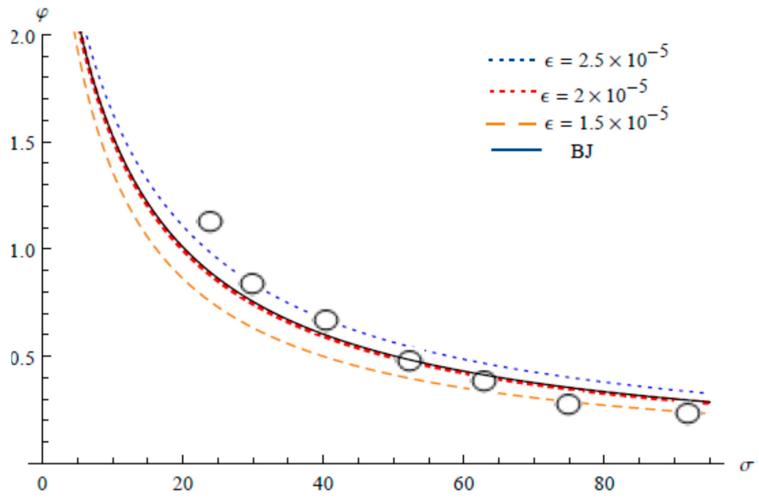
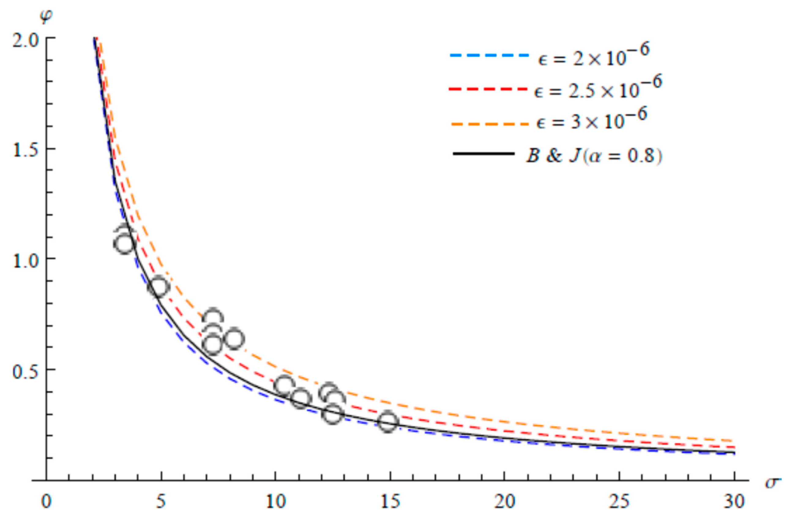
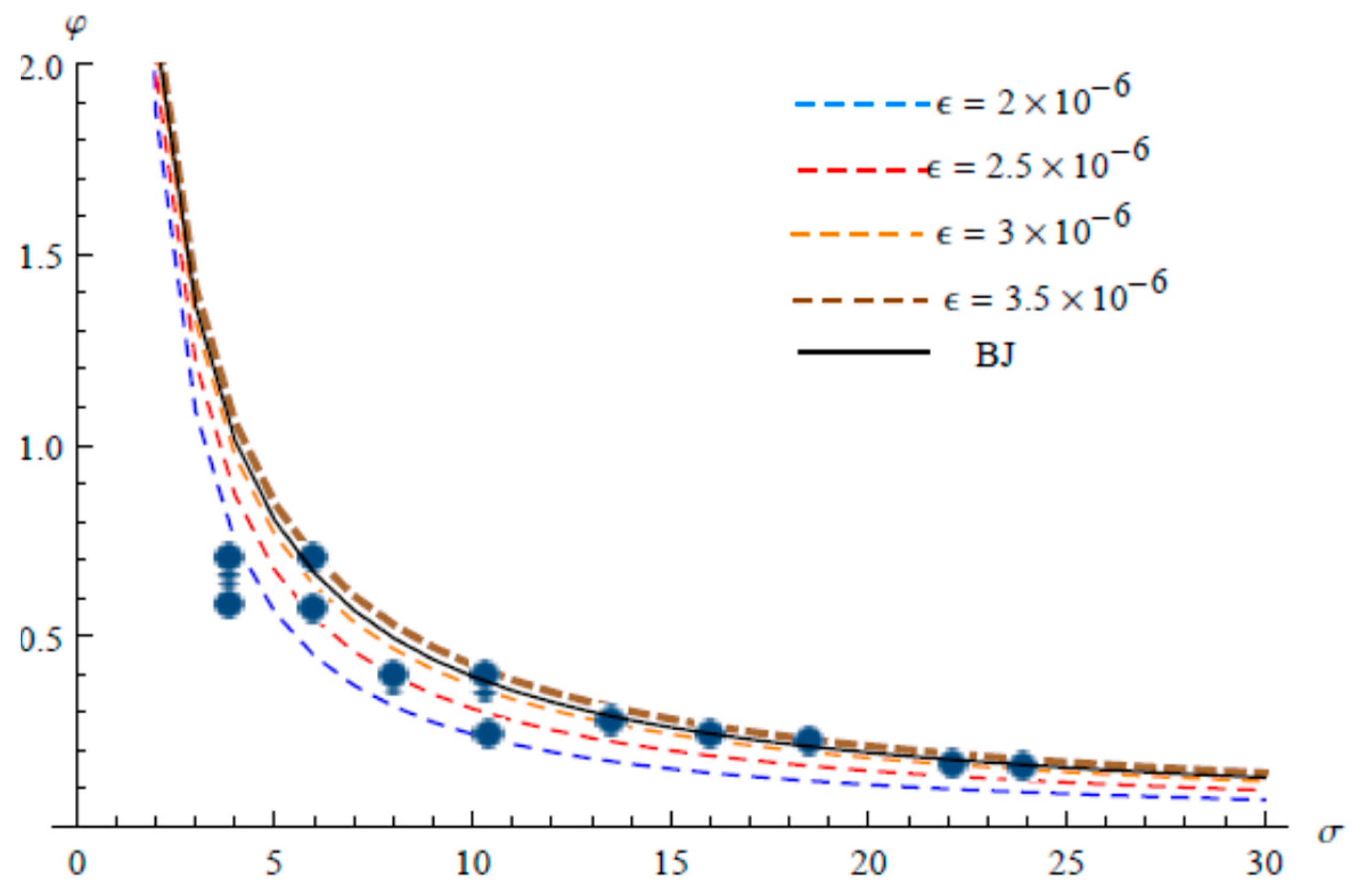
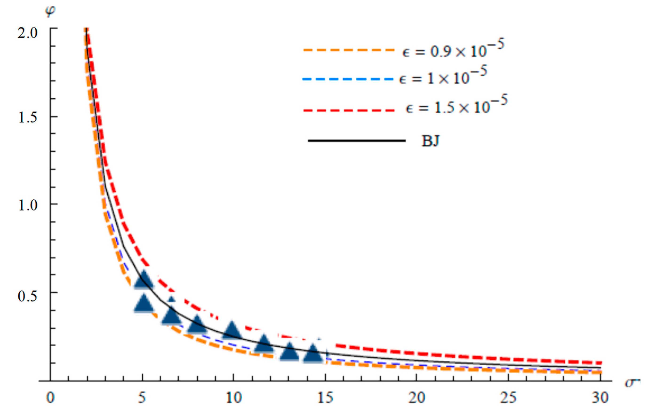
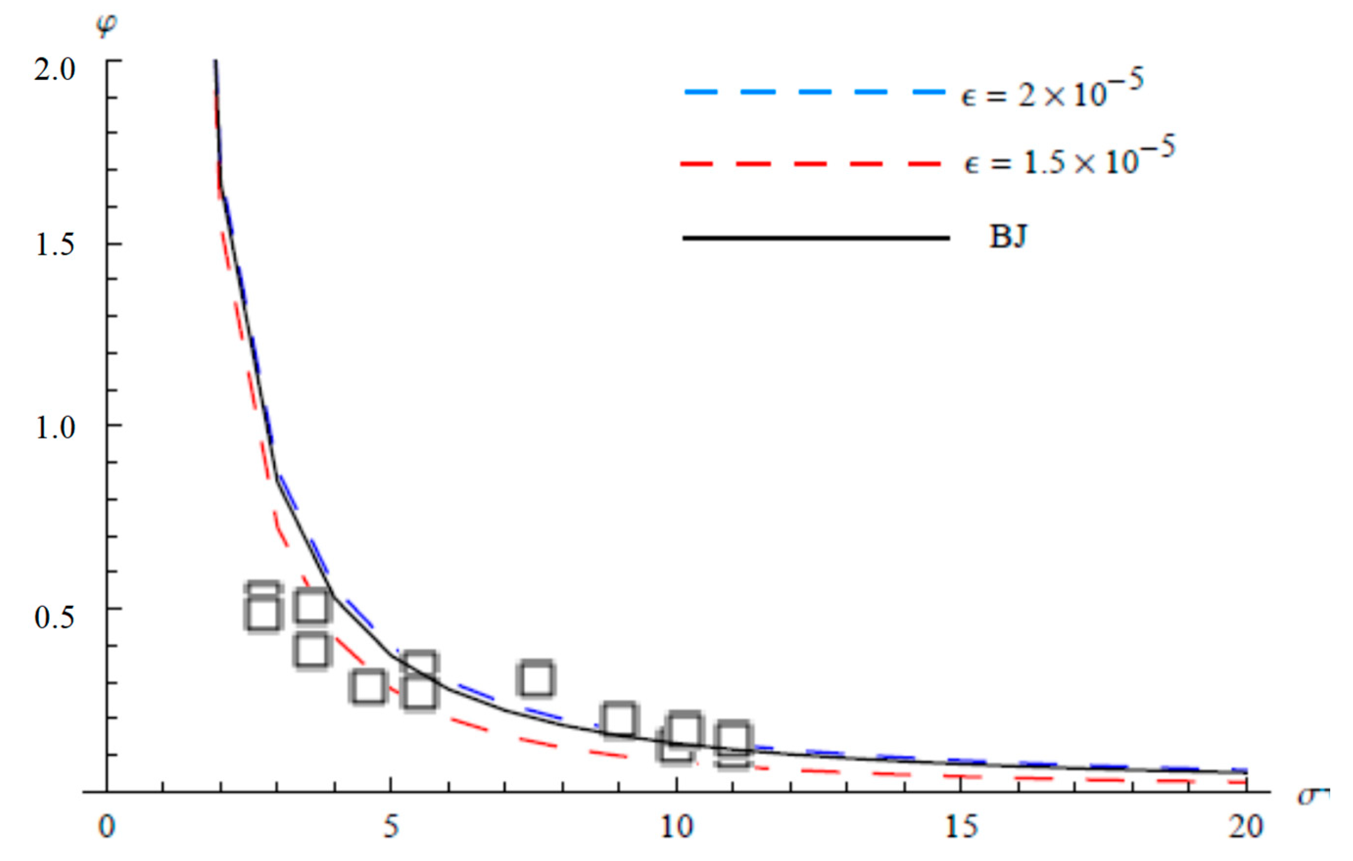
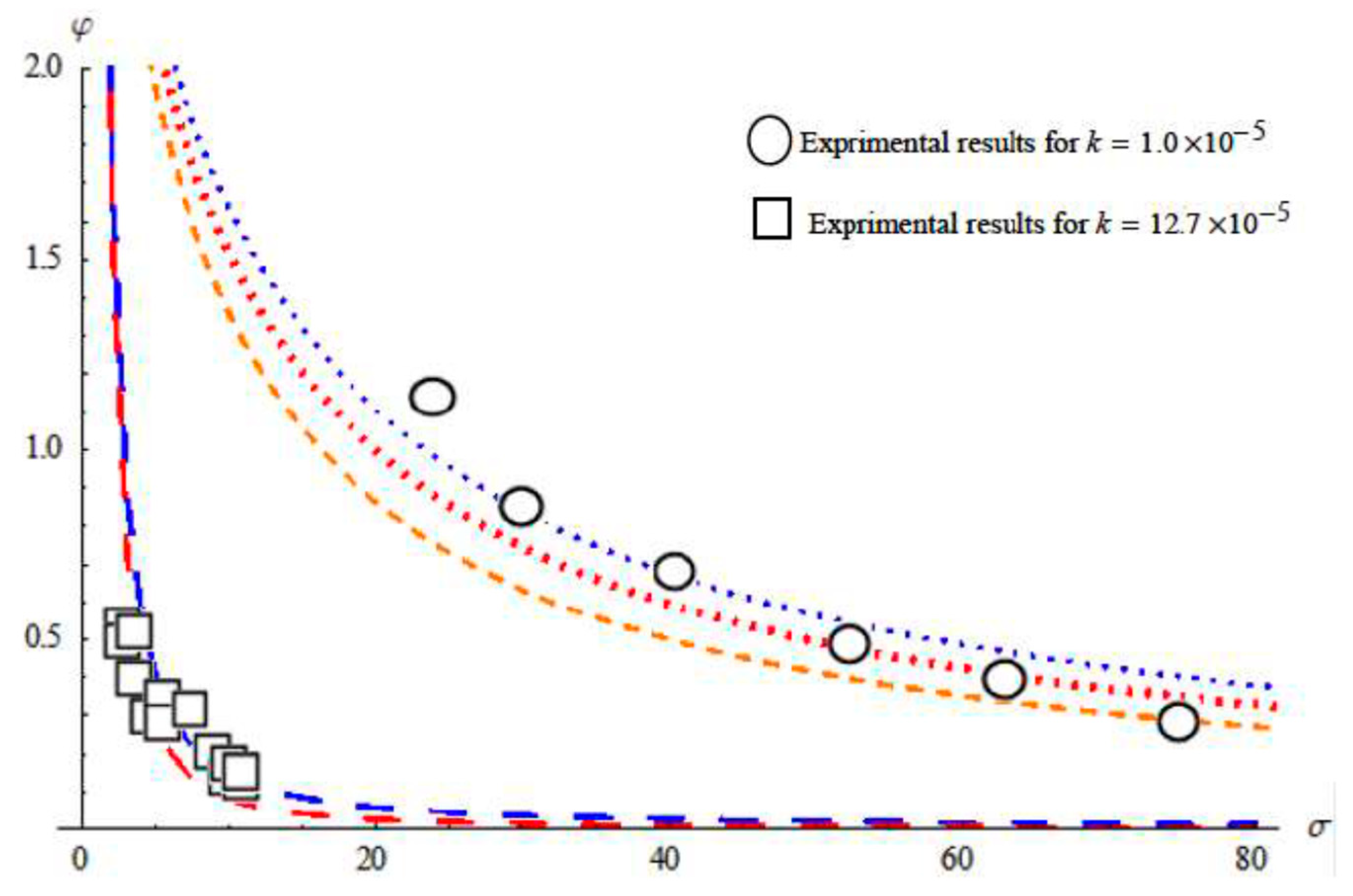
Table 1 shows that the range of ϵ to apply the boundary condition is obtained by the finite element method and is used to evaluate the fractional of increase in mass flow rate φ . Here, a two-element solution is formulated by taking equally spaced nodes at x = 0 ,   ϵ / 2 ,   ϵ . Note that the arrangement of the α -values in the table in the fourth column corresponds to the ϵ -values of the third column (meaning α = 2.45519 for ϵ = 0.2 × 10 5 and α = 1.02221 for ϵ = 1.5 × 10 5 for Fometal B). For Fometal with k 0 = 1.1 × 10 5 and Fometal A.B, C the data show a good agreement with the curves obtained by using the boundary condition (22) at the porous wall, at a certain range of thickness of the interface (as appeared in Figure 2, Figure 3, Figure 4 and Figure 5). For the Aloxite A and B, the results obtained by the FEM are coincide with the analytical solution obtained by Beavers and Joseph [2] (Figure 6 and Figure 7). With respect to the experiments, it is not possible to find values of ϵ for these materials that allow the curves to pass through all the experimental points simultaneously. However, the appeared values of ϵ give the best fit with the experimental points. The highest values for the thickness ϵ are reached by the Aloxite B. As depicted in Figure 8, the experiment and the numerical results agree for Fometal C at σ < 20 while for Aloxite A is partially agree for 20 < σ < 80 . The fourth column in the table shows the range of α corresponding the thickness and compared with values of α proposed by B&J. The comparison between Aloxite A and Fometal C (Figure 8) shows that the experimental results of the Aloxite A spread over a range of σ much greater than the Fometal C which provides an explicit dependence of φ on the thickness of the interface.
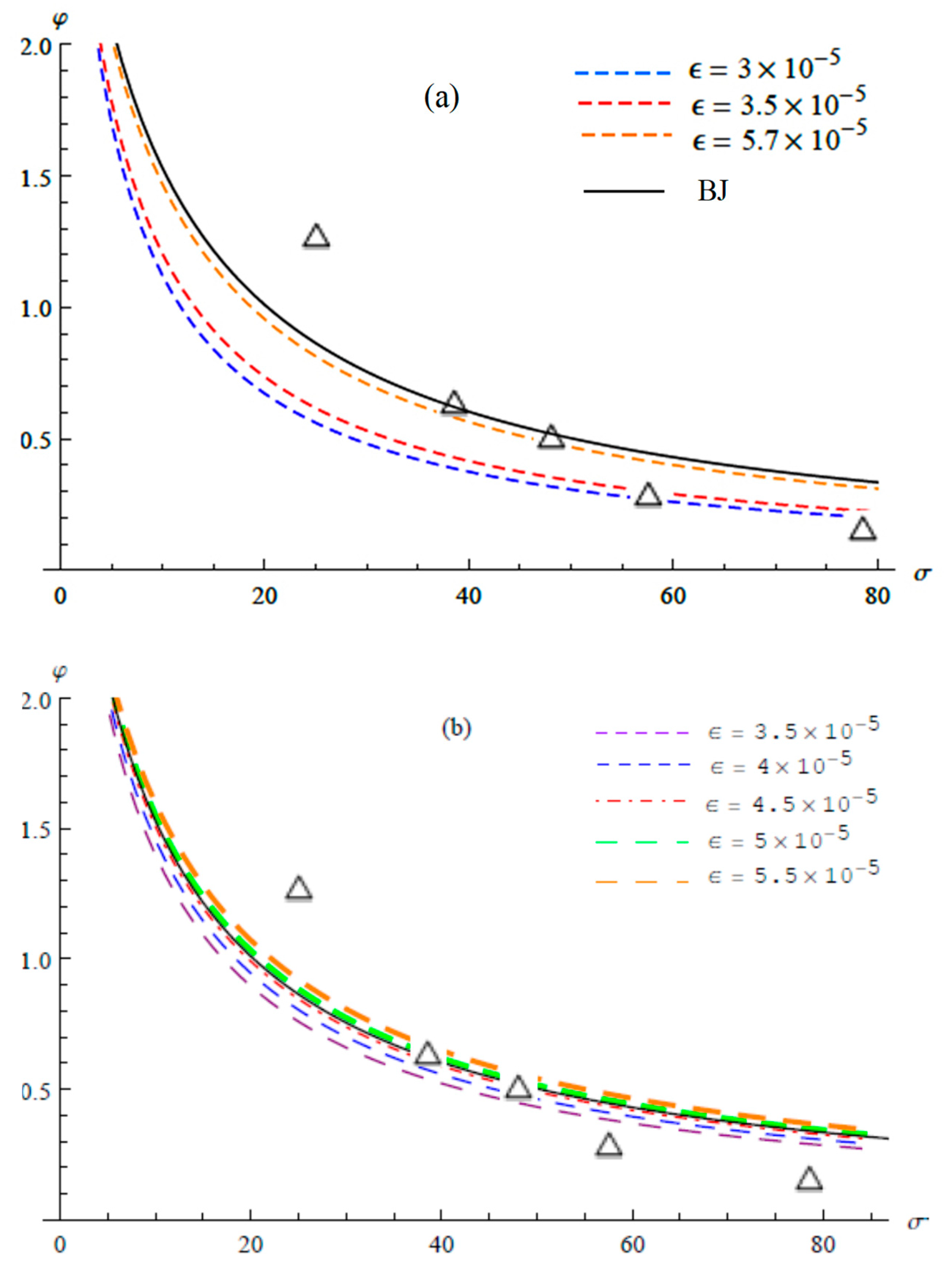
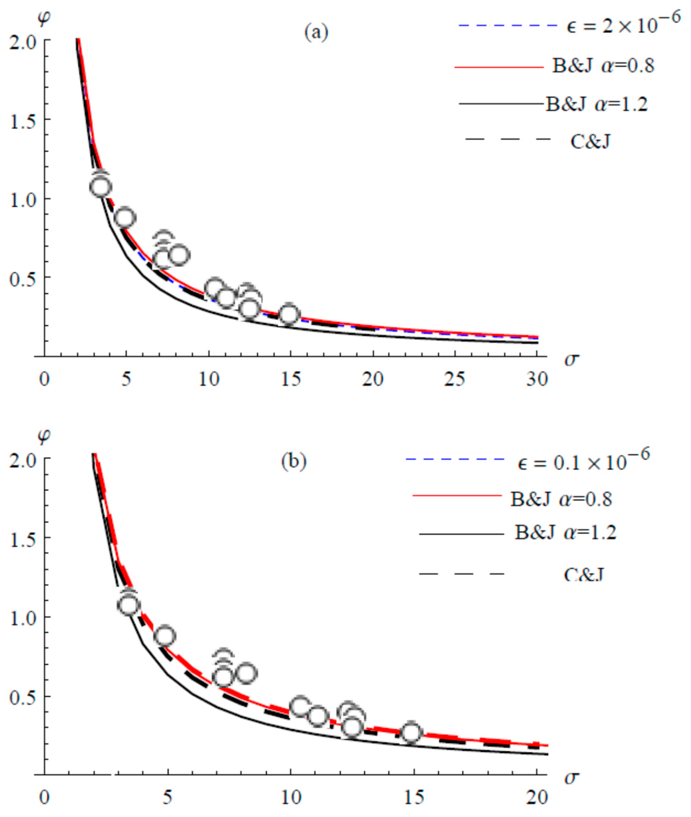
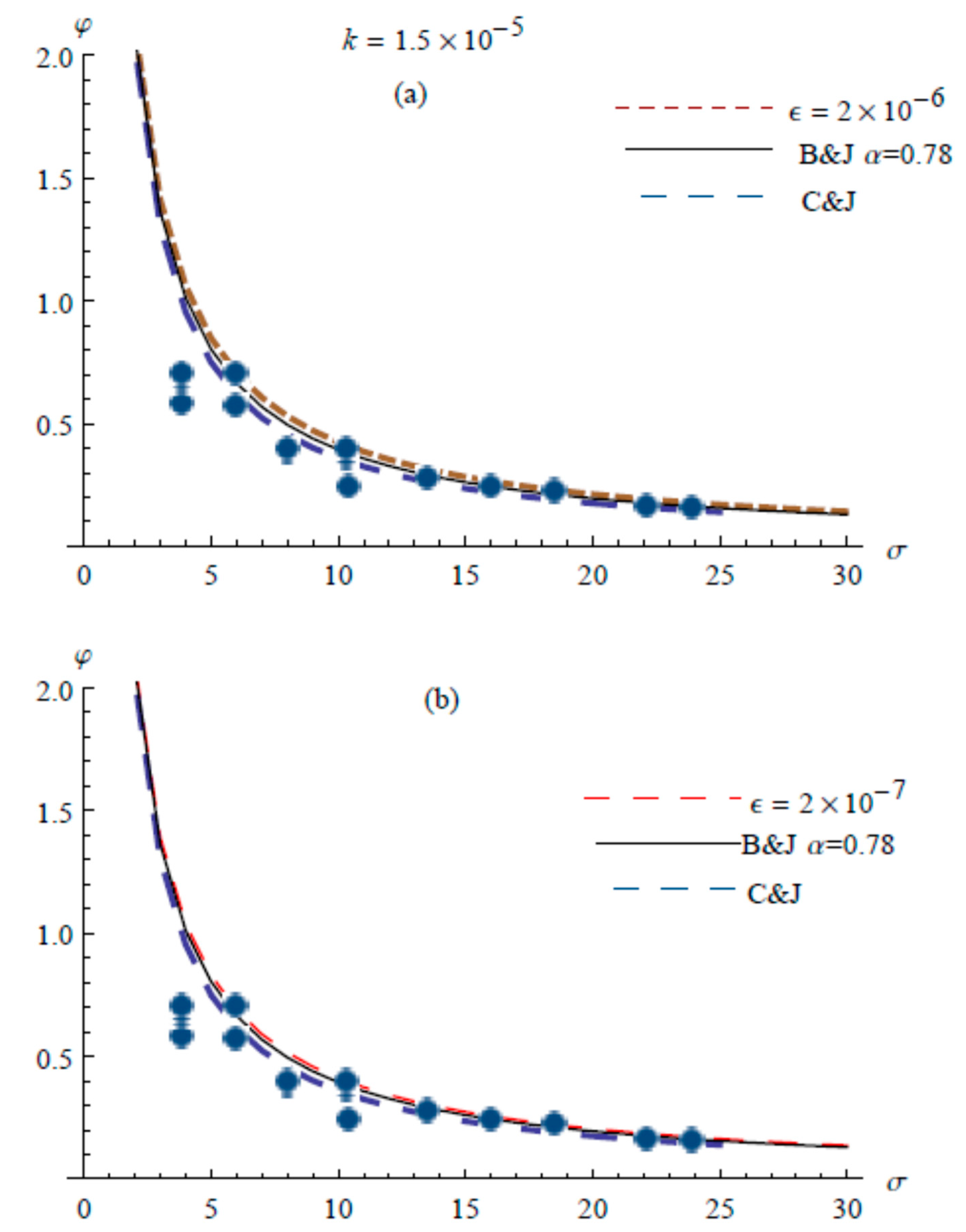
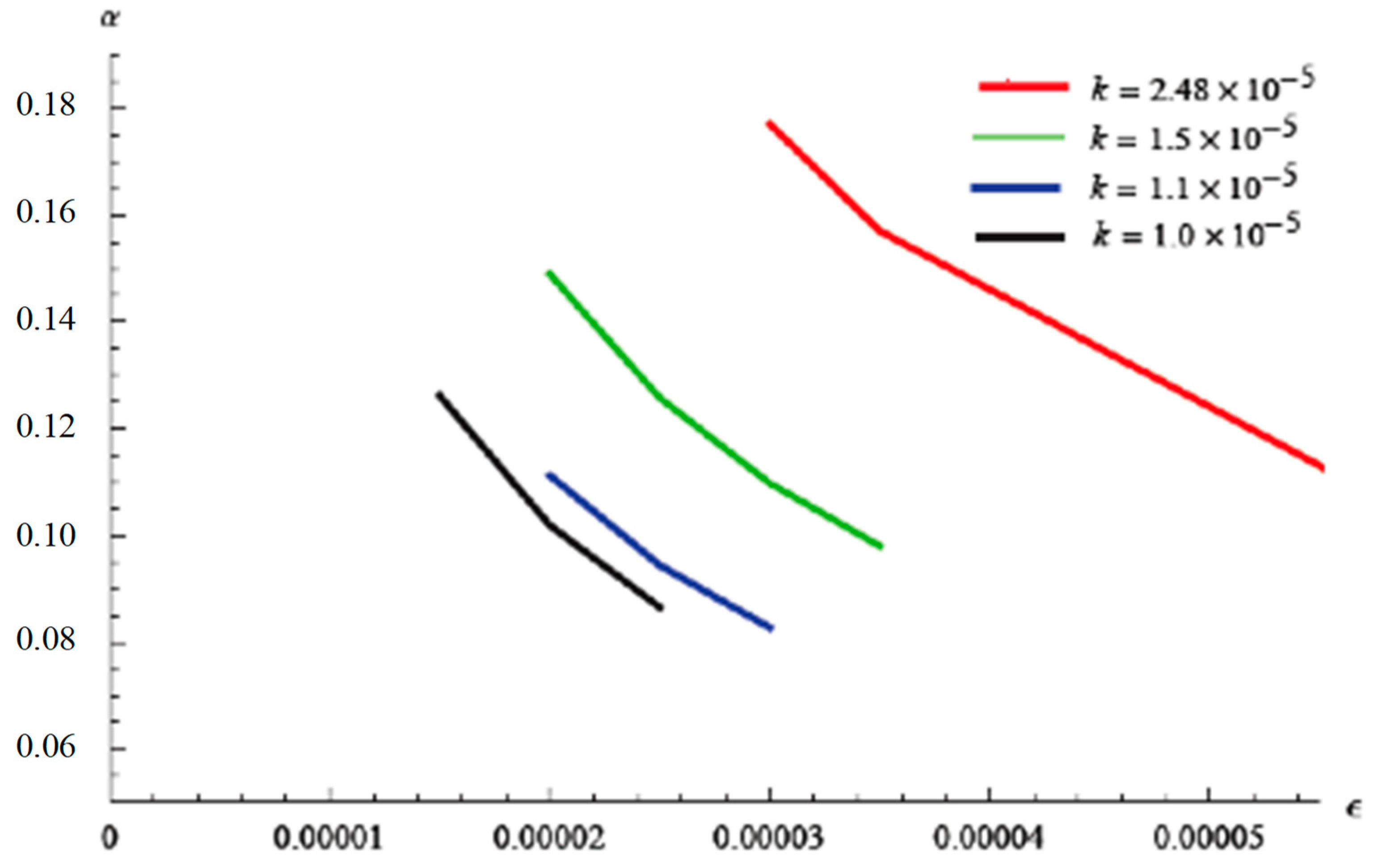
Table 2 shows that the range of ϵ to apply the boundary condition that is obtained by the finite element method. Four element solution is formulated by taking equally spaced nodes at x = 0 , ϵ / 4 ,   ϵ / 2   , 3 ϵ / 4 ,   ϵ . A comparison was made between the two-element and four elements in FEM. It is clear from the Figure 9, the agreement between them and the analytical results is at value ϵ = 2.0 × 10 6 and ϵ = 0.1 × 10 6 in the first and second method, respectively, for k   = 1.1 × 10 5 . For the permeability k   = 1.5 × 10 5 the curves in both methods apply with the analytical method when the value of epsilon is equal to ϵ = 2.0 × 10 6   and   ϵ = 2.0 × 10 7 (Figure 10). Finally, the agreement between them and the analytical results at the value 5.7 × 10 5 and 5.0 × 10 5 . In the first and second method respectively at k   = 2.48 × 10 5 (Figure 7). Figure 11 shows the relationship between ϵ and α for different values of k . The reverse relationship between ϵ and α values is clear in Figure 11.

6. Discussion

In this study, we used the materials listed in the table so we could compare the numerical results obtained by the analytical and experimental results conducted by Beavers and Joseph. Table 1 shows the numerical results using the FEM fit with the analytical solution and experimental data of Beavers and Joseph [2] for the Fometal and partially for the Aloxite. It is noticed that the range ϵ in case of Aloxite is greater than that for Fometal, which could be due to the irregular nature of Aloxite, as mentioned above. Relation (19) is true only within the range of ϵ that appeared in the table. The numerical data indicated that values of Γ2 range from 21.830 to 35.552 for Aloxite, from 165.663 to 201.374 for Fometal with low permeability, and 295.077 to 1203.67 for Fometal with a high permeability.
As mentioned above, α = k 0   Γ 2 is true within the values of ϵ the indicated and is compared with the values considered by Beavers and Joseph [2]. Figure 8, where α is plotted against ϵ , shows that α decreases with the increase of ϵ , which the outcomes of values of ϵ from the numerical and experimental results agree with. The comparison with Beavers and Joseph [2] for Fometal B ,   C , and Aloxite A shows that the values of α, drop within a numerically evaluated range. For example, for Fometal B, the value of the thickness ϵ that makes α = 1.45 the same value obtained by Beavers and Joseph) is ϵ = 1.2 × 10 5 (evaluated from α = Γ 2 k 0 ). Also, for Fometal C, the value of the thickness ϵ that makes α = 4.0 (the same value obtained Beavers and Joseph) is ϵ = 1.9 × 10 5 . For the other materials, the values of α suggested by Beavers and Joseph are completely outside the range of α as evaluated numerically.
For Aloxite B there is a slight difference in α values and completely different for the first Fometal and Fometal A, and these results are subject to the properties of the porous medium at the transition zone.
For Table 1 and Table 2, alpha has upper and a lower bounds, whereas there is a specific value in the results derived by Beaver and Joseph. Beaver and Joseph indicated that the alpha values differ according to the fluid used in the experiment. Then it is expected that if different types of fluids are used in the same porous material, then alpha values will fall in the specified period obtained by the FEM.
Figure 5 compares the curve that represents φ for the thickness ϵ = 2 × 10 5 when dividing the interfacial region into the two elements in Figure 5a and the four elements in Figure 5b. It illustrates the convergence of numerical computations in both cases to the analytical solution developed by Beaver and Joseph. Figure 7 shows the affinity of the numerical results with the analytical and experimental cases in the case of dividing the interface into two and four elements, but for a different thickness of the interfacial area.
Another discussion concerns the velocity in the interfacial zone. According to relation (25), the velocity profile in the interfacial zone ( ϵ x 3 0 ) is a straight line in x 3 for the range of ϵ that appeared in Table 1.

7. Conclusions

In this work, flow in a channel over a porous medium under a constant pressure gradient is studied. The boundary conditions that should be applied to the inhomogeneous interface zone with variable permeability between the two homogeneous regions of free fluid and porous medium are derived. The up scaled Navier-Stokes equation that is used to describe the flow in the two homogeneous regions is assumed to hold in the inhomogeneous interface zone with variable permeability. The finite element method has been used to solve the problem in the whole domain, where the velocity and the stress are continuous across the interface. The computational results show that the stress condition is related to the thickness of the inhomogeneous interface zone with variable permeability.
Good agreement is obtained between the computational results and the Beavers and Joseph [2] experiment by adjusting the values of the thickness of the transition zone. In particular, it was able to correctly predict the slope of the fractional increase in mass flow rate φ versus the non-dimensional height of the free fluid region for the Aloxite experiments. Despite this, the values of the thickness had to be adjusted to obtain good agreement with the available data.
This study shows that the obtained boundary condition using the Finite Element Method is true at a specified thickness values of the transition zone for both Fometal and Aloxite materials. Furthermore, this methodology is applicable to a wide range of transport phenomena in engineering problems [16,17,18,19,20,21,22,23,24,25,26,27,28,29,30,31,32] and of transport phenomena in biological problems [33,34,35]. Finally, an expression of α is obtained and the numerical results on both the permeability and the thickness of the transition zone. Besides, a comparison with the suggested α values of Reference [2] is carried out.

Author Contributions

Both authors contributed to the work presented in this paper as follows: Conceptualization, A.H.S. and M.A.F.; methodology, A.H.S. and M.A.F.; software, M.A.F.; validation, A.H.S. and M.A.F.; formal analysis, A.H.S.; investigation, A.H.S. and M.A.F.; resources, A.H.S. and M.A.F.; data curation, A.H.S. and M.A.F.; writing—original draft preparation, A.H.S.; writing—review and editing, M.A.F.; visualization, A.H.S. and M.A.F.; supervision, M.A.F. All authors have read and agreed to the published version of the manuscript.

Funding

This research received no external funding.

Conflicts of Interest

The authors declare no conflict of interest.

Appendix A

Consider the problem
d 2 u d x 2 + x u = Ω                                             x j   x   x j + 1
subject to the boundary condition
u ( x j ) = u j ,       u ( x j + 1 ) = u j + 1
The problem domain is divided into 2 elements (or 4 elements) bounded by 3 values (or 5 values) x i of the independent variable, so that x 1 = x j   a n d   x 2 = x j + 1 . An approximate solution is assumed in the form
u ( x ) = i = 1 2 N i ( x ) u i
The interpolation functions are defined as
N 1 ( x ) = x j + 1 x x j + 1 x j                                   x j   x   x j + 1
N 1 ( x ) = x x j x j + 1 x j                                   x j   x   x j + 1 .
The interpolation functions satisfy the conditions
N 1 ( x = x j ) = 1                                         N 1 ( x = x j + 1 ) = 0
N 2 ( x = x j ) = 0                                           N 1 ( x = x j + 1 ) = 1 .
Applying the Galerkin weighted residual criterion results in
x j x j + 1 N i ( x ) d 2 u d x 2 d x + x j x j + 1 x N i ( x ) d x x j x j + 1 Ω N i ( x ) d x = 0             i = 1 , 2 .
Applying integration by parts to the first integral results in
N i ( x ) d u d x | x j x j + 1 x j x j + 1 d N i d x d u d x d x + x j x j + 1 x N i ( x ) d x x j x j + 1 Ω N i ( x ) d x = 0     i = 1 , 2 .
Equation (A7) is equivalent to the two equations, is
x j x j + 1 d N 1 d x d u d x d x = x j x j + 1 x N 1 ( x ) d x x j x j + 1 Ω N 1 ( x ) d x + d u d x | x j  
x j x j + 1 d N 2 d x d u d x d x = x j x j + 1 x N 2 ( x ) d x x j x j + 1 Ω N 2 ( x ) d x d u d x | x j + 1 .
Using (A3) setting j = 1 and substituting in Equation (A8) yields
x 1 x 2 d N 1 d x [ u 1 d N 1 d x + u 2 d N 2 d x ] d x = x 1 x 2 x N 1 ( x ) d x x 1 x 2 Ω N 1 ( x ) d x + d u d x | x 1  
x j x 2 d N 2 d x [ u 1 d N 1 d x + u 2 d N 2 d x ] d x = x j x 2 x N 2 ( x ) d x x j x 2 Ω N 2 ( x ) d x d u d x | x 2  
which are of the form
[ k 11 k 12 k 21 k 22 ] { u 1 u 2 } = { F 1 F 2 }
where
k i j = x 1 x 2 d N i d x d N j d x d x                                       i , j = 1 , 2 .

References

  1. Carraro, T.; Goll, C.; Marciniak-Czochra, A.; Mikelic, A. Effective interface conditions for the forced infiltration of a viscous fluid into a porous medium using homogenization. Comput. Methods Appl. Mech. Eng. 2015, 292, 195–220. [Google Scholar] [CrossRef] [Green Version]
  2. Beavers, G.S.; Joseph, D.D. Boundary conditions at a naturally permeable wall. J. Fluid Mech. 1967, 30, 197–207. [Google Scholar] [CrossRef]
  3. Saffman, P.G. On the boundary condition at the interface of a porous medium. Stud. Appl. Math. 1971, 1, 93–101. [Google Scholar] [CrossRef]
  4. Carraro, T.; Goll, C.; Marciniak-Czochra, A.; Mikelic, A. Pressure jump interface law for the Stokes—Darcy coupling: Confirmation by direct numerical simulations. J. Fluid Mech. 2013, 732, 510–536. [Google Scholar] [CrossRef] [Green Version]
  5. Kaviany, M. Principles of Heat Transfer in Porous Media, 2nd ed.; Springer: New York, NY, USA, 1995; pp. 71–78. [Google Scholar]
  6. Sahraoui, M.; Kaviany, M. Slip and no-slip velocity boundary conditions at interface of porous, plain media. Int. J. Heat Mass Transf. 1992, 35, 927–943. [Google Scholar] [CrossRef] [Green Version]
  7. Marciniak-Czochra, A.; Mikelic, A. Effective pressure interface law for transport phenomena between an unconfined fluid and a porous medium using homogenization. Multiscale Model. Simul. 2012, 10, 285–305. [Google Scholar] [CrossRef] [Green Version]
  8. Jäger, W.; Mikelic, A. On the interface boundary conditions by Beavers, Joseph and Saffman. J. Appl. Math. 2000, 60, 1111–1127. [Google Scholar]
  9. Jäger, W.; Mikelic, A.; Neuß, N. Asymptotic analysis of the laminar viscous flow over a porous bed. J. Sci. Stat. Comput. 2001, 22, 2006–2028. [Google Scholar] [CrossRef] [Green Version]
  10. Murdoch, A.I.; Soliman, A. On the slip-boundary condition for liquid flow over planar porous boundaries. Proc. R. Soc. Lond. A 1999, 455, 1315–1340. [Google Scholar] [CrossRef]
  11. Chandesris, M.; Jamet, D. Boundary conditions at a planar fluid-porous interface for a Poiseuille flow. Int. J. Heat Mass Transf. 2006, 49, 2137–2150. [Google Scholar] [CrossRef] [Green Version]
  12. Sheikholeslami, M.; Rezaeianjouybari, B.; Darzi, M.; Shafee, A.; Li, Z.; Nguyen, T.K. Application of nano-refrigerant for boiling heat transfer enhancement employing an experimental study. Int. J. Heat Mass Transf. 2019, 141, 974–980. [Google Scholar] [CrossRef]
  13. Sheikholeslami, M.; Haq, R.; Shafee, A.; Li, Z. Heat transfer behavior of nanoparticle enhanced PCM solidification through an enclosure with V shaped fins. Int. J. Heat Mass Transf. 2019, 130, 1322–1342. [Google Scholar] [CrossRef]
  14. Sheikholeslami, M. Simulation of nanofluid flow and natural convection in a porous media under the influence of electric field using CVFEM. Int. J. Heat Mass Transf. 2018, 120, 772–781. [Google Scholar] [CrossRef]
  15. Hutton, D. Fundamentals of Finite Element Analysis; Mc GRAW HILL: Boston, MA, USA, 2004; pp. 131–156. [Google Scholar]
  16. Fahmy, M.A. A time-stepping DRBEM for magneto-thermo-viscoelastic interactions in a rotating nonhomogeneous anisotropic solid. Int. J. Appl. Mech. 2011, 3, 711–734. [Google Scholar] [CrossRef]
  17. Fahmy, M.A. A time-stepping DRBEM for the transient magneto-thermo-visco-elastic stresses in a rotating non-homogeneous anisotropic solid. Eng. Anal. Bound. Elem. 2012, 36, 335–345. [Google Scholar] [CrossRef]
  18. Fahmy, M.A. Transient magneto-thermoviscoelastic plane waves in a non-homogeneous anisotropic thick strip subjected to a moving heat source. Appl. Math. Model. 2012, 36, 4565–4578. [Google Scholar] [CrossRef]
  19. Fahmy, M.A. Numerical modeling of transient magneto-thermo-viscoelastic waves in a rotating nonhomogeneous anisotropic solid under initial stress. Int. J. Model. Simul. Sci. Comput. 2012, 3, 1250002. [Google Scholar] [CrossRef]
  20. Fahmy, M.A. The effect of rotation and inhomogeneity on the transient magneto-thermoviscoelastic stresses in an anisotropic solid. ASME J. Appl. Mech. 2012, 79, 1015. [Google Scholar] [CrossRef]
  21. Fahmy, M.A. Transient magneto-thermo-viscoelastic stresses in a rotating nonhomogeneous anisotropic solid with and without a moving heat source. J. Eng. Phys. Thermophys. 2012, 85, 950–958. [Google Scholar] [CrossRef]
  22. Fahmy, M.A. Transient magneto-thermo-elastic stresses in an anisotropic viscoelastic solid with and without moving heat source. Numer. Heat Transf. Part A Appl. 2012, 61, 547–564. [Google Scholar] [CrossRef]
  23. Fahmy, M.A. Implicit-Explicit time integration DRBEM for generalized magneto-thermoelasticity problems of rotating anisotropic viscoelastic functionally graded solids. Eng. Anal. Bound. Elem. 2013, 37, 107–115. [Google Scholar] [CrossRef]
  24. Fahmy, M.A. Generalized magneto-thermo-viscoelastic problems of rotating functionally graded anisotropic plates by the dual reciprocity boundary element method. J. Therm. Stresses 2013, 36, 284–303. [Google Scholar] [CrossRef]
  25. Fahmy, M.A. A three-dimensional generalized magneto-thermo-viscoelastic problem of a rotating functionally graded anisotropic solids with and without energy dissipation. Numer. Heat Transf. Part A Appl. 2013, 63, 713–733. [Google Scholar] [CrossRef]
  26. Fahmy, M.A. A Computerized DRBEM model for generalized magneto-thermo-visco-elastic stress waves in functionally graded anisotropic thin film/substrate structures. Latin Am. J. Solids Structures 2014, 11, 386–409. [Google Scholar] [CrossRef] [Green Version]
  27. Fahmy, M.A. Shape design sensitivity and optimization for two-temperature generalized magneto-thermoelastic problems using time-domain DRBEM. J. Therm. Stresses 2018, 41, 119–138. [Google Scholar] [CrossRef]
  28. Fahmy, M.A. Shape design sensitivity and optimization of anisotropic functionally graded smart structures using bicubic B-splines DRBEM. Eng. Anal. Bound. Elem. 2018, 87, 27–35. [Google Scholar] [CrossRef]
  29. Fahmy, M.A. Modeling and Optimization of Anisotropic Viscoelastic Porous Structures Using CQBEM and Moving Asymptotes Algorithm. Arabian J. Sci. Eng. 2019, 44, 1671–1684. [Google Scholar] [CrossRef]
  30. Fahmy, M.A. A new LRBFCM-GBEM modeling algorithm for general solution of time fractional order dual phase lag bioheat transfer problems in functionally graded tissues. Numer. Heat Transf. Part A Appl. 2019, 75, 616–626. [Google Scholar] [CrossRef]
  31. Fahmy, M.A. Design Optimization for A Simulation of Rotating Anisotropic Viscoelastic Porous Structures Using Time-Domain OQBEM. Math. Comput. Simul. 2019, 66, 193–205. [Google Scholar] [CrossRef]
  32. Fahmy, M.A. A new convolution variational boundary element technique for design sensitivity analysis and topology optimization of anisotropic thermo-poroelastic structures. Arab J. Basic Appl. Sci. 2020, 27, 1–12. [Google Scholar] [CrossRef]
  33. Fahmy, M.A. A New Computerized Boundary Element Algorithm for Cancer Modeling of Cardiac Anisotropy on the ECG Simulation. Asian J. Res. Comput. Sci. 2018, 2, 1–10. [Google Scholar] [CrossRef] [Green Version]
  34. Fahmy, M.A. Boundary Element Algorithm for Modeling and Simulation of Dual Phase Lag Bioheat Transfer and Biomechanics of Anisotropic Soft Tissues. Int. J. Appl. Mech. 2018, 10, 1850108. [Google Scholar] [CrossRef]
  35. Fahmy, M.A. Boundary Element Modeling and Simulation of Biothermomechanical Behavior in Anisotropic Laser-Induced Tissue Hyperthermia. Eng. Anal. Bound. Elem. 2019, 101, 156–164. [Google Scholar] [CrossRef]
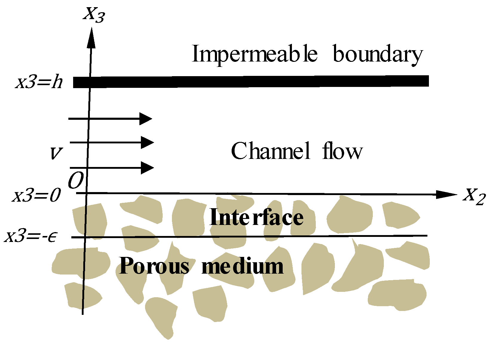
Figure 1. Geometry of the problem.
Computation 08 00014 g001
Figure 2. Frictional increase in the mass flow rate for Aloxite A ( k = 1.0 × 10 5 ) .
Computation 08 00014 g002
Figure 3. Fractional increase in the mass flow rate for Aloxite B ( k = 2.48 × 10 5 ) with 4 elements.
Computation 08 00014 g003
Figure 4. Fractional increase in mass flow rate for Fometal ( k = 1.1 × 10 5 ) with 2 -elements.
Computation 08 00014 g004
Figure 5. Compares ion between (a) 2-element and (b) 4-elements in FEM for k = 1.1 × 10 5 .
Computation 08 00014 g005
Figure 6. Fractional increase in mass flow rate for Fometal A ( k   = 1.5 × 10 5 ) 2-elememt.
Computation 08 00014 g006
Figure 7. Compares ion between (a) 2 elements and (b) 4 elements in FEM for k = 1.5 × 10 5 .
Computation 08 00014 g007
Figure 8. Fractional increase in mass flow rate for Fometal B ( k   = 6.1 × 10 5 ) for 2 elements.
Computation 08 00014 g008
Figure 9. Fractional increase in mass flow rate for Fometal C ( k   = 12.7 × 10 5 ) for 2 elements.
Computation 08 00014 g009
Figure 10. Comparison of ions between k = 1.0 × 10 5 and k = 12.7 × 10 5
Computation 08 00014 g010
Figure 11. Comparison between α verses ϵ for materials have low permeability.
Computation 08 00014 g011
Table 1. Permeability of the porous specimens used in Beavers and Joseph experiments and the corresponding values thickness of the interface and α for the interfacial region divided into 2 elements.
Porous Species Permeability   k 0 Range   of   ϵ Values   of   α Values   of   α for Beavers and Joseph
Fometal 1.1 × 10 5 2.0 3.0 × 10 5 0.867991 0.082716 0.8
Fometal A 1.5 × 10 5 0.2 0.35 × 10 5 0.148943 0.707495 0.78
Fometal B 6.1 × 10 5 0.9 1.5 × 10 5 2.45519 1.02221 1.45
Fometal C 12.7 × 10 5 1.5 2.0 × 10 5 13.5647 3.32535 4.0
Aloxite A 1.0 × 10 5 1.5 2.5 × 10 5 0.126144 0.086583 0.1
Aloxite B 2.48 × 10 5 3.0 5.7 × 10 5 0.177047 0.108711 0.1
Table 2. Permeability of the porous specimens used in Beavers and Joseph experiments and the corresponding values thickness of the interface and α for the interfacial region divided into 4 elements.
Porous Species Permeability   k 0 Range   of   ϵ Values   of   α Values   of   α for Beavers and Joseph
Fometal 1.1 × 10 5 0.01 0.03 × 10 5 0.773944 0.622062 0.8
Fometal A 1.5 × 10 5 0.01 0.035 × 10 5 0.815955 – 0.657912 0.78
Aloxite B 2.48 × 10 5 3.5–5.5 × 10 5 0.11951 0.0912537 0.1