Article

Underwater Optical Wireless Communications with Chromatic Dispersion and Time Jitter

by
George D. Roumelas
1,
Hector E. Nistazakis
1,*,
Argyris N. Stassinakis
1,
Christos K. Volos
2 and
Andreas D. Tsigopoulos
3
1
Department of Electronics, Computers, Telecommunications and Control, Faculty of Physics, National and Kapodistrian University of Athens, 15784 Athens, Greece
2
Laboratory of Nonlinear Systems—Circuits & Complexity, Department of Physics, Aristotle University of Thessaloniki, GR-541 24 Thessaloniki, Greece
3
Department of Battle Systems, Naval Operations, Sea Studies, Navigation, Electronics and Telecommunications, Hellenic Naval Academy, Hadjikyriakou Ave., GR-185 39 Piraeus, Greece
*
Author to whom correspondence should be addressed.
Computation 2019, 7(3), 35; https://doi.org/10.3390/computation7030035
Submission received: 30 April 2019 / Revised: 9 July 2019 / Accepted: 9 July 2019 / Published: 11 July 2019
(This article belongs to the Special Issue Optical Wireless Communication Systems)

Abstract

:
The obsolete communication systems used in the underwater environment necessitates the development and use of modern telecommunications technologies. One such technology is the optical wireless communications, which can provide very high data rates, almost infinite bandwidth and very high transmission speed for real time fast and secure underwater links. However, the composition and the optical density of seawater hinder the communication between transmitter and receiver, while many significant effects strongly mitigate the underwater optical wireless communication (UOWC) systems’ performance. In this work, the influences of chromatic dispersion and time jitter are investigated. Chromatic dispersion causes the temporal broadening or narrowing of the pulse, while time jitter complicates the detection process at the receiver. Thus, the broadening of the optical pulse due to chromatic dispersion is studied and the influence of the initial chirp is examined. Moreover, the effect of the time jitter is also taken into consideration and for the first time, to the best of our knowledge, a mathematical expression for the probability of fade is extracted, taking into account the influence of both of the above-mentioned effects for a UOWC system. Finally, the appropriate numerical results are presented.

1. Introduction

The most common underwater wireless communication systems used acoustic waves, which are used in order to transfer the information signal, mainly because of the relatively large link lengths that can be achieved. However, these systems offer limited efficiency due to their short bandwidth, their high transmission losses, the time dependent multipath, the extended delay, the Doppler broadening and the low security level. These effects lead to intense variations in the behavior of the acoustic channel, resulting in the limitation of the system’s available bandwidth [1,2,3].
Taking into account that this technology cannot support high data rate transmission, the use of electromagnetic (EM) waves, in the range of the radio frequency (RF), has been proposed because they offer a much higher bandwidth and propagation speed. However, their inherent physical properties limit their potential. Thus, to compensate for the very high losses that they suffer from during their propagation in the underwater environment, very high-power sources are required, while the large magnitude of the antennas needed represents another disadvantage [4,5,6].
Therefore, both acoustic and RF EM waves are practically unable to sustain an underwater wireless communication system of high efficiency and stability. A potential technology that could improve their quality is the underwater optical wireless communications (UOWC). This technology can offer a significant solution with low energy consumption and very high data rate that can even reach throughputs of the order of Gbps for a link’s distance of a few hundred meters. Moreover, it is capable of preventing interferences and offers a secure connection between the transmitter and the receiver [5,7,8].
The challenge presented in the case of the optical signal lays in the severe variability of the oceanic environment, where the optical beam propagation is affected significantly mainly by absorption and scattering [4,6,8,9,10,11]. Absorption is an irreversible thermal process in which the energy of the photon is lost because of its interaction with the molecules of water and other particles, while scattering is the change in direction of the propagation of the photon and it is caused by its interaction with other particles. These factors significantly affect the maximum range of the underwater optical wireless link and consequently the reliability of the communication system.
Thus, scattering leads to spatial dispersion, which is the broadening of the cross-section of the beam, while the chromatic dispersion results in the temporal broadening or narrowing of the pulse. The chromatic dispersion, or group velocity dispersion (GVD), appears due to the frequency dependent refractive index of the medium, where the optical pulse propagates, and it has been proven that this phenomenon significantly affects the pulse propagation in fiber optics and FSO communication systems [12,13,14,15,16,17,18]. Both dispersion types, mainly, downgrade the operation of the communication systems by significantly decreasing the link’s distance. Additionally, high levels of ambient light, especially on the upper levels of the ocean, also have a negative impact on their performance, since they interfere with the optical signal during detection and can cause errors [19].
Another significant factor that hinders the smooth operation of the communication systems and the UOWC is the time jitter effect. In a theoretical basis, the receiver and the transmitter are perfectly synchronized and the detection of the received signal is accomplished exactly at the correct time, i.e., at the center of the relevant time slot, where the pulse is assumed to have its maximum amplitude. However, for communication systems with very high data rates, such as UOWC, i.e., short pulses, where the optical beam propagates through the water, the pulse detection could not be achieved exactly at the center of the time slot. This can be caused by many reasons, such as imperfect synchronization between transmitter and receiver, detection delays, scattering due to the propagation, etc. The specific effect has been thoroughly studied, mainly in fiber optics communication systems [20,21,22,23,24,25], but to the best of the authors’ knowledge, it has not yet been investigated for optical wireless communication systems, which are using longitudinal Gaussian pulses as the information carrier. Additionally, it will be shown below that the influence of this effect is very significant for the case of high data rate communication systems, such as UOWC, with very high bandwidths.
In this work, the performance of an UOWC system is studied, focusing only on the significant influence of GVD and time jitter effects. A realistic empirical model for the refraction index of seawater is used, and the corresponding mathematical expressions for the longitudinal pulse’s broadening and maximum available bit rate are derived. Moreover, the joint influence of losses, time jitter and GVD at the probability of the fade performance of the UOWC system is studied in detail for the first time for such a system, and novel mathematical expressions are derived. Thus, the next step that could follow this work would be the performance estimation that takes into account other physical phenomena as well, appearing along the underwater propagation path, but this is beyond the scope of this work.
The remainder of this work is organized as follows: in Section 2 the underwater channel is studied, while in Section 3 the mathematical models for various performance characteristics of the optical channel are extracted. Next, in Section 4, the way that time jitter could interfere with the detection process is described along with the influence of the losses, while in Section 5 the probability of fade due to the losses and the time jitter effect is estimated as a criterion of the performance of the system. Finally, in Section 6, the corresponding numerical results are presented.

2. Group Velocity Dispersion Estimation

A significant factor that degrades the performance of a UOWC system is scattering because of the decrease in the received optical power [26,27,28]. In order to estimate its influence at the UOWC performance, the seawater’s refractive index should be estimated. An accurate empirical model for the estimation of the refractive index has been introduced by McNeil [29], and is given as:
n ( λ , T e m p , S , P ) = 1.3247 + 3.3 × 10 3 λ 2 3.2 × 10 7 λ 4 2.5 × 10 6 T e m p 2 + ( 5 2 × 10 2 T e m p ) ( 4 × 10 5 S ) + ( 1.45 × 10 5 P ) ( 1.021 6 × 10 4 S ) ( 1 4.5 × 10 3 T e m p )
where λ stands for the wavelength in nm, Temp for the temperature in °C, S for the salinity in ‰ and P for the pressure in kg/cm2. The latter can be estimated as a function of the sea’s depth as [29]:
P = 0.05 d ( ρ 0 + ρ d )
where d is the depth in meters (m), ρ 0 the density at the surface in g/ml and ρ d the density at depth d in g/ml. However, for seawater conditions Temp = 0 °C and S = 35 ‰, the Equation (2) is usually approximated as [29]:
P 0.104 d .
Taking into account that the angular frequency ω of the optical beam is given as a function of the optical wavelength, λ, and the speed of light inside the medium, v, i.e., λ = 2 π v ω 1 , the refractive index of Equation (1) can be given as:
n ( ω ) = 1.3247 + 3.3 × 10 3 ω 2 ( 2 π v ) 2 3.2 × 10 7 ω 4 ( 2 π v ) 4 2.5 × 10 6 T e m p 2 + 4 × 10 5 S ( 5 2 × 10 2 T e m p ) + 1.45 × 10 5 P ( 1.021 6 × 10 4 S ) ( 1 4.5 × 10 3 T e m p )
From Equation (4), is clear that, the seawater’s refractive index depends on the optical signal’s frequency, which indicates the manifestation of chromatic dispersion. Thus, taking into account that the propagation constant is given as [12,14,20]:
β ( ω ) = n ( ω ) ω c
with c being the speed of light in vacuum, from Equations (4) and (5) we can conclude in the following expression that:
β ( ω ) = 1.3247 ω c + 3.3 × 10 3 ω 3 4 π 2 v 2 c 3.2 × 10 7 ω 5 16 π 4 v 4 c 2.5 × 10 6 T e m p 2 ω c + 4 × 10 5 ( 5 2 × 10 2 T e m p ) S ω c + 1.45 × 10 3 ( 1.021 6 × 10 4 S ) ( 1 4.5 × 10 3 T e m p ) P ω c
Next, by expanding the propagation constant of Equation (5) in a Fourier series around the angular frequency ω 0 and keeping terms up to the second order, we obtain [12,15]:
β ( ω ) β 0 + β 1 ( ω ω 0 ) + 1 2 β 2 ( ω ω 0 ) 2 +
with β q = ( d q β / d ω q ) ω = ω 0 for q = 1, 2, …, β 1 1 represents the group velocity of the envelope of the optical pulse and β 2 stands for the GVD parameter [12,15]. The influence of a higher order terms of Equation (7) are not taken into account because their contribution here can be assumed as negligible [12].
The inverse group velocity parameter, β1, parameter is estimated as [12]:
β 1 = ( d β d ω ) ω = ω 0 = 1 c [ 1.3247 + 3.3 × 10 3 3 ω 0 2 4 π 2 v 2 1 × 10 7 ω 0 4 π 4 v 4 2.5 × 10 6 T e m p 2 + 4 × 10 5 S ( 5 2 × 10 2 T e m p ) + + 1.45 × 10 5 P ( 1.021 6 × 10 4 S ) ( 1 4.5 × 10 3 T e m p ) ]
while the parameter β2 is given as [12]:
β 2 = ( d 2 β d ω 2 ) ω = ω 0 = 1 c [ 3.3 × 10 3 3 ω 0 2 π 2 v 2 4 × 10 7 ω 0 3 π 4 v 4 ] .
The normalized amplitude, U(z,T), of a pulse propagating along axis z inside a dispersive medium, is given as [12,15,30]:
i U z = β 2 2 2 U T 2
where T stands for the retarded time, which is defined as T = t β 1 z , representing a time frame of the pulse propagating with the group velocity along the pulse [12,17,31,32,33].
By assuming that the UOWC system under consideration is using the envelope of a longitudinal chirped Gaussian pulse as the bit carrier, which is a realistic assumption for common optical wireless communication systems, the pulse’s initial condition is given as [12,30,34]:
U ( 0 , T ) = exp [ ( 1 + i C ) T 2 2 T 0 2 ]
where C is the chirp effect parameter and T0 stands for the parameter that represents the half width at 1/e intensity of the pulse. A specific pulse is chirped if its carrier frequency changes with time [20]. Thus, when C is positive, the instantaneous frequency increases linearly from the leading to the following edge and it is called up-chirp, while the opposite occurs for negative values of C and is called down-chirp.
The physical meaning of chirp has to do with the broadening of the optical pulse’s frequency components, compared with the corresponding pulses without chirp. Thus, the width of the pulse in the frequency domain is given as [12]:
Δ ω = T 0 1 1 + C 2
where Δω stands for the half width of the pulse at the 1/e intensity point at the frequency domain of the pulse [12,30].
Using Equations (10) and (11), the mathematical expression that describes the evolution of the envelope of the normalized longitudinal Gaussian pulse into the dispersive media, is given as [12,15]:
U ( z , T ) = T 0 T 0 2 i β 2 z ( 1 + i C ) exp { ( 1 + i C ) T 2 2 [ T 0 2 i β 2 z ( 1 + i C ) ] }
and its pulsewidth, Tz, after propagation distance z, by substituting the β2 parameter through Equation (9), is given as [12,16,30]:
T z = 1 T 0 { [ T 0 2 + C z ω 0 π 2 v 2 c ( 4.95 × 10 3 4 × 10 7 ω 0 2 π 2 v 2 ) ] 2 + + [ z ω 0 π 2 v 2 c ( 4.95 × 10 3 4 × 10 7 ω 0 2 π 2 v 2 ) ] 2 } 1 / 2
As it is perceived from Equation (14), the broadening or narrowing of the longitudinal Gaussian pulse depends on the sign of the chirp parameter. More specifically, for positive values of C, the pulse’s width always increases, while for negative chirp values, Tz decreases up to Tz,min for a specific critical propagation distance zmin, and after this point, Tz starts increasing monotonically. This critical propagation distance is estimated from Equation (14) and is given as [15,30]:
z min = | C | T 0 2 1 + C 2 ( 3.3 × 10 3 3 ω 0 2 π 2 v 2 c 4 × 10 7 ω 0 3 π 4 v 4 c ) 1
while the corresponding minimum pulsewidth is evaluated as [12]:
T z , min = T 0 ( 1 + C 2 ) 1 / 2 .

3. Link Performance Estimation

In optical telecommunication systems, the information signal is transmitted through the link as a coded sequence of optical pulses, which represent the bits of the information signal. Thus, the width, i.e., the duration, of the pulses determines the available bit rate, R, of the communication system. This means that it is probable that the pulse broadening induced by dispersion will complicate the signal detection procedure and lead to errors if the pulse exceeds the predefined bit slot. Consequently, the optical pulse’s broadening limits the bit rate of a stable link of length z.
For the UOWC system under consideration, which, as mentioned above, uses longitudinal chirped Gaussian pulses as bit carriers and the GVD parameter β2, it has been proven that the bit rate of the system, R, is determined through the following inequality [12]:
2 2 T m R 1
where Tm represents the maximum value between T0 and Tz for transmission in distance z, i.e., T m = max { T 0 , T z } . The equality part of Equation (17) corresponds to the maximum bit rate, Rmax, of the link. Thus, the Rmax value for the UOWC link is obtained from Equation (17) and is given as:
R max = 2 4 T m .
Next, from the Tm definition of Equation (18) and using Equation (14), the following mathematical expression for the estimation of Rmax depending on the propagation distance is obtained:
R max = { 2 4 T 0 , for   T z < T 0 2 T 0 4 { [ T 0 2 + C z ω 0 π 2 v 2 c ( 4.95 × 10 3 4 × 10 7 ω 0 2 π 2 v 2 ) ] 2 + + [ z ω 0 π 2 v 2 c ( 4.95 × 10 3 4 × 10 7 ω 0 2 π 2 v 2 ) ] 2 } 1 / 2 for   T z T 0 .

4. Time Jitter and Attenuation

The instantaneous irradiance of the received pulse, Ir, is given as [15]:
I r = P 0 | u ( z , T ) | 2 = P 0 B S p exp [ T 2 A ]
where P0 and Sp represent the peak power of the Gaussian pulse and the total speckle surface of the optical beam at the receiver’s size, respectively [15]. Additionally, the parameters A and B are given as, A = T 0 2 + 2 β 2 z C + T 0 2 β 2 2 z 2 ( C 2 + 1 ) and B = 1 + 2 T 0 2 β 2 z C + T 0 4 β 2 2 z 2 ( C 2 + 1 ) .
Here, we assume that the probability of receiving each specific bit before or after the center of the corresponding timeslot is equal and thus, in this work, the effect of time jitter is considered to be statistically described by a normal distribution with zero mean value. Obviously, according to the circumstances that are taken into account, the distribution function that is chosen to describe the time jitter effect can be different. However, the analysis that follows is unique and can be used for any other suggestion. The probability density function (PDF) of the normal distribution model with mean value μ T and variance σ T 2 is given as [20,35]:
f T ( T ) = 1 2 π σ T exp [ ( T μ T ) 2 2 σ T 2 ] .
Taking into account that due to the time jitter, the optical pulse is not detected exactly at the center of the optical pulse, the received irradiance does not achieve its maximum value. More specifically, the maximum intensity of each pulse is obtained at T = 0 ps and is given through Equation (20), as:
I max = P 0 B S p .
Thus, the normalized irradiance of the Gaussian pulse at the receiver’s input is estimated from Equations (20) and (22), as:
I G = I r I max = exp [ T 2 A ] .
Another very significant parameter, which should be taken into account for the underwater propagation of the optical pulse, is the attenuation. Thus, if we assume that the transmitted normalized irradiance, I, reaches the unity exactly at the transmitter’s output for T = 0, then this value will decrease as a function of the propagation distance, z, due to the propagation losses [5,8,36,37], and it will be given as follows at the receiver’s input [38,39]:
I ( z , T ) = I L I G .
Next, taking into account the attenuation law of Beer–Lampert [7,40], and substituting (23) into (24), we conclude that the normalized irradiance is given as:
I ( z , T ) = exp [ ζ z + T 2 A ]
where the parameter ζ depends on the characteristics of the sea water and the parameters of the optical beam that is used in the UOWC system.

5. The Probability of Fade

A very significant performance and availability metric for the communication systems is the probability of fade, which expresses the probability of the received irradiance being lower than a specific threshold value, Ith, which constitutes a characteristic value for the receiver of each communication system and is given as [41,42,43]:
P F = Pr ( I I t h ) .
Taking into account Equation (25), it can be seen that for T = 0 ps and z = 0 km, i.e., without time jitter and exactly at the output of the transmitter, the parameter I is taking its highest value, i.e., I = 1, while for any other values, of T or/and z, i.e., with time jitter and for link length z, the value of I is getting smaller than one.
More specifically, taking into account only the time jitter effect at the Gaussian pulse, the time shift from the center of the time slot as a function of the normalized irradiance is estimated through Equation (23) and is given as:
T = ± A ln ( I G ) .
Thus, by substituting into Equation (27) the value of IG,th with that of Ith = ILIG,th from Equation (24), the time shift value which corresponds to Ith can be either +|Tth| or −|Tth| and consequently, the result of Equation (26), considering the time jitter effect and the propagation losses, for an information signal that is using Gaussian pulses, can be estimated through the following integrals:
P F = Pr ( I I t h ) = = Pr ( T | T t h | ) Pr ( T | T t h | ) = | T t h | f T ( T ) d T + | T t h | + f T ( T ) d T = = 1 2 π σ T { | T t h | exp [ ( T μ T ) 2 2 σ T 2 ] d T + | T t h | + exp [ ( T μ T ) 2 2 σ T 2 ] d T }
Then, by solving the integrals of Equation (28) we obtain that:
P F = σ T 2 { e r f c [ | T t h | + μ T 2 σ T ] + e r f c [ | T t h | μ T 2 σ T ] }
where erfc(.) stands for the complementary error function.
Next, by substituting, the Tth value from Equation (27) and using Equations (24) and (25), we conclude that the probability of fade for the UOWC system under consideration, taking into account the GVD and the time jitter effect along with the water’s attenuation for longitudinal Gaussian pulse propagation, is given through the following closed form mathematical expression:
P F = σ T 2 { e r f c [ A [ ζ z + ln ( I t h ) ] + μ T 2 σ T ] + e r f c [ A [ ζ z + ln ( I t h ) ] μ T 2 σ T ] } , f o r I t h 1 .

6. Numerical Results

Following the above process and implementing it to the McNeil model for the index of refraction, below we present the corresponding numerical results, which were extracted for typical conditions, i.e., ζ = 0.151 m−1, for the case of clean ocean [37], S = 35 and Temp = 0 °C [29]. It should be mentioned here that similar numerical results could be obtained easily for any other values of salinity and temperature according to each case, using the above derived mathematical expressions.
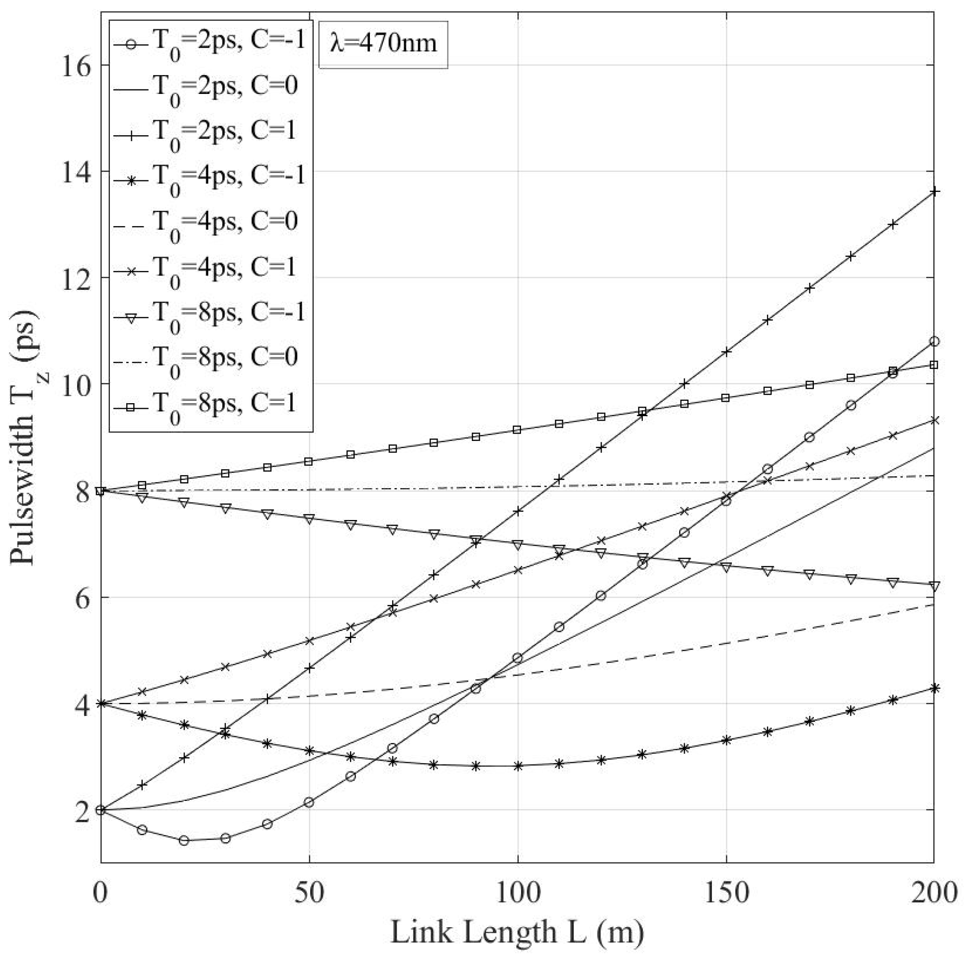
By using Equation (9) for the GVD parameter β2 and Equation (14), the diagrams of Figure 1 are extracted. In Figure 1, the broadening of the pulse Tz is presented, as a function of their initial duration, i.e., T0 is equal to 2 ps, 4 ps or 8 ps, for two cases of wavelength, i.e., 470 nm or 550 nm, by assuming C = 0. The results are presented for a total link length of 200 m, since it has been proven that the effective range of an underwater wireless optical system is about 150 m depending on the water’s conditions [44,45,46,47]. For a pulse in that wavelength range, the change of the initial pulsewidth can induce important alterations in the behavior of the system. This is shown in Figure 2, where pulses with various initial duration values are presented, and it can be seen that as the propagation distance increases and the initial pulsewidth decreases, the GVD’s influence is getting stronger and not negligible. Such a broadening could lead to high enough bit overlapping during the detection process and consequently, to detection errors and a decrease in bit rate. The situation can be different if an initial chirp is added to the transmitted pulse, as even a small initial chirp can greatly decrease the broadening or even shrink the pulse.
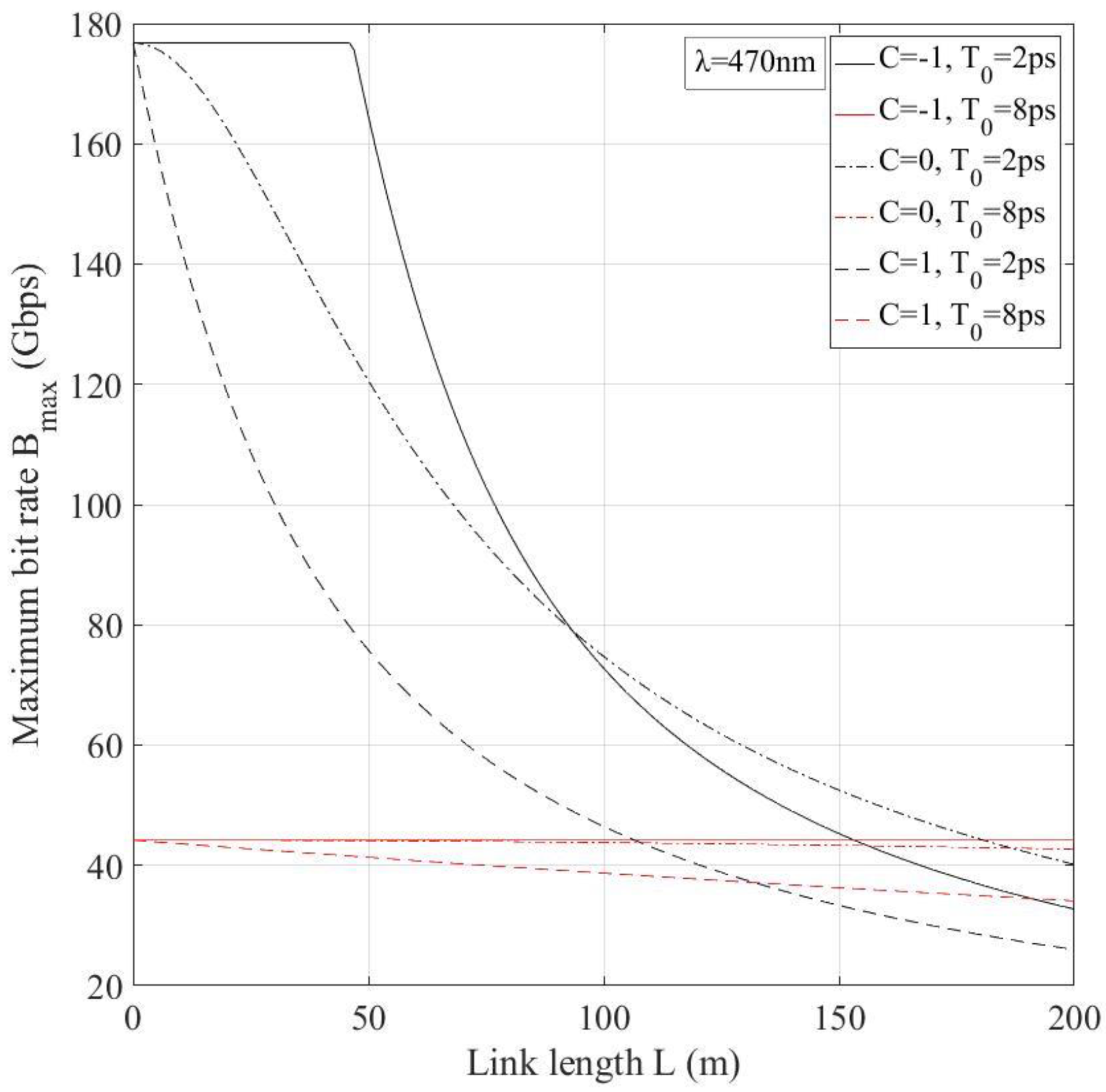
Moreover, using the maximum bit rate criterion defined in Equation (17), it is possible to observe the effect of chromatic dispersion on the maximum bit rate of the system, given by Equation (19). Figure 3 presents the variation of the Rmax of the system for two initial pulsewidths versus the signal’s propagation distance. Relative short pulses, i.e., around 2 ps, can greatly improve the efficiency of the underwater optical communication systems, despite their sensitivity to the effects of dispersion. As already discussed, adding negative initial chirp to the pulse can prevent the pulse from broadening and in some cases can result in its shrinking. Furthermore, it should be mentioned that the influence of the GVD effect is very significant for very short pulses, i.e., very high data rate transmission, even for the cases of short link lengths. More specifically, as it can be seen in Figure 3, the dependence of Rmax on the propagation distance is dominant, even for a link of a few meters, for pulses with T0 = 2 ps.
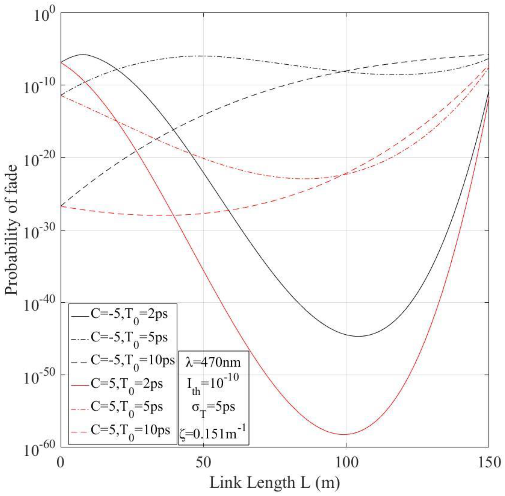
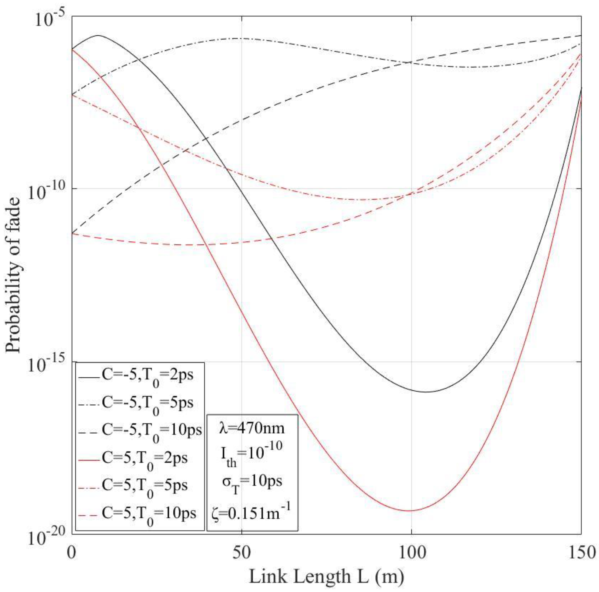
Following the procedure analyzed above, the effect of the time jitter can be investigated by extracting numerical results from Equation (30), which represents the probability of fade for the case of chromatic dispersion, and temporal deviation of the peak of the pulse. The results for various cases of the chirp parameter, the initial pulsewidth and the variance of the time jitter, while the irradiance threshold is fixed at Ith = 1 × 10⁻¹⁰, are presented in Figure 4 and Figure 5. It should be mentioned here that in Figure 4 and Figure 5 we present only the influence of the time jitter effect in longitudinal Gaussian pulse propagation, combined with the losses inflicted on the optical pulse during its propagation through the underwater medium. Apparently, time jitter hinders the efficient detection of the received optical pulse by inducing a kind of outage to the system. This phenomenon is even more intense for pulses with negative inserted chirp, mainly due to the fact that the negative chirp causes the longitudinal narrowing of the pulse and consequently increases its peak, and even slight deviations from the pulse’s center can significantly decrease the optical power that reaches the detector. Additionally, it is clear that the shorter the longitudinal Gaussian pulse is, the more intense the time jitter effect is. Thus, considering that the aim of the UOWC systems is to achieve the maximum possible data rates, short duration pulses are expected to be employed and as shown from Figure 4 and Figure 5, as well as Equations (28)–(30), GVD could play a very detrimental role to the performance of the system.
It should be mentioned here that all the parameters’ values for the link characteristics and the time jitter effect have been chosen in order to be realistic and to present, as clearly as possible, the influence of the time jitter effect on the performance of a UOWC system that is using longitudinal Gaussian pulses as information bits. However, it is clear that any other choice can be realized and the performance of the system can be easily estimated, by means of its probability of fade, through the Equations (29) and (30).

7. Conclusions

In this work, the influence of GVD and time jitter effect at the availability and performance of a realistic UOWC system have been jointly investigated. The time jitter effect has been modeled through the normal distribution, taking into account the corresponding assumptions, while the information bits of the communication system are assumed to be longitudinal Gaussian pulses. Thus, following the proper analysis, new closed form mathematical expressions have been derived for the estimation of the underwater system’s outage probability, taking into account the two above-mentioned effects. Next, using the derived expression in the numerical results section, the very significant influence of these two effects on the system’s performance has been shown, especially for very high data rates, even for propagation distances of a few decades of meters. Finally, many numerical results have been presented for various parameters for realistic UOWC systems.

Author Contributions

Conceptualization, G.D.R. and H.E.N.; methodology, G.D.R., A.N.S. and H.E.N.; software, G.D.R. and A.N.S.; validation, G.D.R., A.N.S. and H.E.N.; formal analysis, G.D.R., H.E.N., A.N.S., C.K.V. and A.D.T.; investigation, G.D.R. and H.E.N.; resources, G.D.R., H.E.N., C.K.V. and A.D.T.; writing—original draft preparation, G.D.R. and H.E.N.; writing—review and editing, H.E.N., C.K.V. and A.D.T.; supervision, H.E.N.; funding acquisition, H.E.N.

Funding

H.E.N. and A.N.S. acknowledges the funding from the European Union’s Horizon 2020 research and innovation program under grant agreement No: 777596. G.D.R. acknowledges that this research is co-financed by Greece and the European Union (European Social Fund-ESF) through the Operational Program “Human Resources Development, Education and Lifelong Learning” in the context of the project “Strengthening Human Resources Research Potential via Doctorate Research” (MIS-5000432), implemented by the State Scholarships Foundation (ΙΚΥ).

Conflicts of Interest

The authors declare no conflict of interest.

References

  1. Melodia, T.; Kulhandjian, H.; Kuo, L.-C.; Demirors, E. Advances in Underwater Acoustic Networking. In Mobile Ad Hoc Networking; John Wiley & Sons, Inc.: Hoboken, NJ, USA, 2013; pp. 804–852. [Google Scholar]
  2. Stojanovic, M.; Preisig, J. Underwater Acoustic Communication Channels: Propagation Models and Statistical Characterization. IEEE Commun. Mag. 2009, 47, 84–89. [Google Scholar] [CrossRef]
  3. Akyildiz, I.F.; Pompili, D.; Melodia, T. Challenges for efficient communication in underwater acoustic sensor networks. ACM SIGBED Rev. 2007, 1, 3–8. [Google Scholar] [CrossRef]
  4. Anguita, D.; Brizzolara, D.; Parodi, G. Prospects and Problems of Optical Diffuse Wireless Communication for Underwater Wireless Sensor Networks. In Wireless Sensor Networks: Application-Centric Design; IntechOpen: London, UK, 2010. [Google Scholar] [Green Version]
  5. Kaushal, H.; Kaddoum, G. Underwater Optical Wireless Communication. IEEE Access 2016, 4, 1518–1547. [Google Scholar] [CrossRef]
  6. Liu, L.; Zhou, S.; Cui, J. Prospects and Problems of Wireless Communication for Underwater Sensor Networks. Wirel. Commun. Mob. Comput. 2008, 8, 977–994. [Google Scholar]
  7. Zeng, Z.; Fu, S.; Zhang, H.; Dong, Y.; Cheng, J. A Survey of Underwater Optical Wireless Communications. IEEE Commun. Surv. Tutor. 2017, 19, 204–238. [Google Scholar] [CrossRef]
  8. Saeed, N.; Celik, A.; Al-Naffouri, T.Y.; Alouini, M.-S. Underwater Optical Wireless Communications, Networking, and Localization: A Survey. Ad Hoc Netw. 2019, 94, 101935. [Google Scholar] [CrossRef]
  9. Haltrin, V.I. Chlorophyll-based model of seawater optical properties. Appl. Opt. 1999, 38, 6826–6832. [Google Scholar] [CrossRef] [PubMed] [Green Version]
  10. Zhang, H.; Cheng, J.; Wang, Z. On Integrated Stochastic Channel Model for Underwater Optical Wireless Communications. In Proceedings of the 2018 IEEE International Conference on Communications (ICC), Kansas City, MO, USA, 20–24 May 2018; pp. 1–6. [Google Scholar]
  11. Young, E.Y.S.; Bullock, A.M. Underwater-airborne laser communication system: Characterization of the channel. High-Power Lasers Appl. 2003, 4975, 146–157. [Google Scholar]
  12. Agrawal, G.P. Nonlinear Fiber Optics, 3rd ed.; Academic Press: San Diego, CA, USA, 2001. [Google Scholar]
  13. Crisp, J. Introduction to Fiber Optics, 2nd ed.; Newnes: Oxford, UK, 2005. [Google Scholar]
  14. Ramaswami, R.; Sivarajan, K.N.; Sasaki, G.H. Optical Networks, 3rd ed.; Elsevier: Burlington, NJ, USA, 2010. [Google Scholar]
  15. Stassinakis, A.N.; Nistazakis, H.E.; Peppas, K.P.; Tombras, G.S. Improving the availability of terrestrial FSO links over log normal atmospheric turbulence channels using dispersive chirped Gaussian pulses. Opt. Laser Technol. 2013, 54, 329–334. [Google Scholar] [CrossRef]
  16. Lu, H.; Zhao, W.; Xie, X. Analysis of temporal broadening of optical pulses by atmospheric dispersion in laser communication system. Opt. Commun. 2012, 285, 3169–3173. [Google Scholar] [CrossRef]
  17. Nistazakis, H.E.; Frantzeskakis, D.J.; Atai, J.; Malomed, B.A.; Efremidis, N.; Hizanidis, K. Multichannel pulse dynamics in a stabilized Ginzburg-Landau system. Phys. Rev. E Stat. Phys. Plasmas Fluids Relat. Interdiscip. Top. 2002, 65, 1–12. [Google Scholar] [CrossRef] [PubMed]
  18. Hizanidis, K.; Malomed, B.A.; Nistazakis, H.E.; Frantzeskakis, D.J. Stabilizing soliton transmission by third-order dispersion in dispersion-compensated fibre links. Pure Appl. Opt. 1998, 7, 57–62. [Google Scholar] [CrossRef]
  19. Jaruwatanadilok, S. Channel Modeling and Performance Evaluation using Vector Radiative Transfer Theory. IEEE J. Sel. Areas Commun. 2008, 26, 1620–1627. [Google Scholar] [CrossRef]
  20. Agrawal, G.P. Fiber-Optic Communication Systems; John Wiley & Sons, Inc.: Hoboken, NJ, USA, 2010. [Google Scholar]
  21. Underhill, M.J. Time jitter and phase noise—Now and in the future? In Proceedings of the 2012 IEEE International Frequency Control Symposium Proceedings, Baltimore, MD, USA, 21–24 May 2012; pp. 1–8. [Google Scholar]
  22. Ghassemlooy, Z.; Arnon, S.; Uysal, M.; Xu, Z.; Cheng, J. Emerging Optical Wireless Communications-Advances and Challenges. IEEE J. Sel. Areas Commun. 2015, 33, 1738–1749. [Google Scholar] [CrossRef]
  23. Grigoryan, V.S.; Menyuk, C.R.; Mu, R.M. Calculation of timing and amplitude jitter in dispersion-managed optical fiber communications using linearization. J. Light. Technol. 1999, 17, 1347–1356. [Google Scholar] [CrossRef]
  24. Gnauck, A.H.; Mecozzi, A.; Clausen, C.B.; Park, S.G.; Shtaif, M. Cancellation of timing and amplitude jitter in symmetric links using highly dispersed pulses. IEEE Photonics Technol. Lett. 2002, 13, 445–447. [Google Scholar]
  25. Santhanam, J.; Agrawal, G.P. Raman-induced timing jitter in dispersion-managed optical communication systems. IEEE J. Sel. Top. Quantum Electron. 2002, 8, 632–639. [Google Scholar] [CrossRef]
  26. Johnson, L.J. The Underwater Optical Channel. 2012, pp. 1–18. Available online: https://www.researchgate.net/publication/280050464_The_Underwater_Optical_Channel/citation/download (accessed on 11 July 2019).
  27. Wei, W.; Zhang, X.; Rao, J.; Wang, W. Time domain dispersion of underwater optical wireless communication. Chin. Opt. Lett. 2011, 9, 030101–030104. [Google Scholar] [CrossRef]
  28. Austin, R.W.; Halikas, G. The index of refraction of seawater. In UC San Diego: Scripps Institution of Oceanography; 1976; Available online: https://escholarship.org/uc/item/8px2019m (accessed on 11 July 2019).
  29. McNeil, G.T. Metrical Fundamentals of Underwater Lens System. Opt. Eng. 1977, 16, 162128. [Google Scholar] [CrossRef]
  30. Marcuse, D. Pulse distortion in single-mode fibers. 3: Chirped pulses. Appl. Opt. 1981, 20, 3573–3779. [Google Scholar] [CrossRef]
  31. Nistazakis, H.E.; Kevrekidis, P.G.; Malomed, B.A.; Frantzeskakis, D.J.; Bishop, A.R. Targeted transfer of solitons in continua and lattices. Phys. Rev. E Stat. Phys. Plasmas Fluids Relat. Interdiscip. Top. 2002, 66, 015601. [Google Scholar] [CrossRef] [PubMed]
  32. Nistazakis, H.E.; Rapti, Z.; Frantzeskakis, D.J.; Kevrekidis, P.G.; Sodano, P.; Trombettoni, A. Rabi switch of condensate wave functions in a multicomponent Bose gas. Phys. Rev. A At. Mol. Opt. Phys. 2008, 78, 023635. [Google Scholar] [CrossRef] [Green Version]
  33. Driben, R.; Malomed, B.A.; Chu, P.L. Transmission of pulses in a dispersion-managed fiber link with extra nonlinear segments. Opt. Commun. 2005, 245, 227–236. [Google Scholar] [CrossRef]
  34. Marcuse, D. Pulse distortion in single-mode fibers. Appl. Opt. 1980, 19, 1653. [Google Scholar] [CrossRef] [PubMed]
  35. Papoulis, A. Probability, Random Variables, and Stochastic Processes, 3rd ed.; McGraw-Hill, Inc.: New York, NY, USA, 1991. [Google Scholar]
  36. Arnon, S. Underwater optical wireless communication network. Opt. Eng. 2010, 49, 015001. [Google Scholar] [CrossRef]
  37. Cochenour, B.; Mullen, L.; Laux, A. Spatial and temporal dispersion in high bandwidth underwater laser communication links. In Proceedings of the MILCOM 2008–2008 IEEE Military Communications Conference, San Diego, CA, USA, 16–19 November 2008. [Google Scholar]
  38. Sandalidis, H.; Tsiftsis, T.; Karagiannidis, G. Optical wireless communications with heterodyne detection over turbulence channels with pointing errors. J. Lightwave Technol. 2009, 27, 4440–4445. [Google Scholar] [CrossRef]
  39. Gappmair, W.; Hranilovic, S.; Leitgeb, E. Performance of PPM on terrestrial FSO links with turbulence and pointing errors. IEEE Commun. Lett. 2010, 14, 468–470. [Google Scholar] [CrossRef]
  40. Johnson, L.J.; Jasman, F.; Green, R.J.; Leeson, M.S. Recent advances in underwater optical wireless communications. Underw. Technol. 2014, 32, 167–175. [Google Scholar] [CrossRef]
  41. Barrios, R.; Dios, F. Probability of fade and BER performance of FSO links over the exponentiated Weibull fading channel under aperture averaging. In Proc. SPIE 8540, Unmanned/Unattended Sensors and Sensor Networks IX; SPIE Security + Defence: Edinburgh, UK, 2012; Volume 8540, p. 85400D. [Google Scholar]
  42. Varotsos, G.K.; Nistazakis, H.E.; Volos, C.K.; Tombras, G.S. FSO links with diversity pointing errors and temporal broadening of the pulses over weak to strong atmospheric turbulence channels. Optik 2016, 127, 3402–3409. [Google Scholar] [CrossRef]
  43. Vetelino, F.S.; Young, C.; Andrews, L. Fade statistics and aperture averaging for Gaussian beam waves in moderate-to-strong turbulence. Appl. Opt. 2007, 46, 3780. [Google Scholar] [CrossRef] [PubMed]
  44. Wang, C.; Yu, H.-Y.; Zhu, Y.-J. A Long Distance Underwater Visible Light Communication System with Single Photon Avalanche Diode. IEEE Photonics J. 2016, 8, 1–11. [Google Scholar] [CrossRef]
  45. Chancey, M.A. Short Range Underwater Optical Communication Links. Master’s Thesis, North Carolina State University, Raleigh, NC, USA, 2005. [Google Scholar]
  46. Partan, J.; Kurose, J.; Levine, B.N. A survey of practical issues in underwater networks. ACM SIGMOBILE Mob. Comput. Commun. Rev. 2007, 11, 23. [Google Scholar] [CrossRef]
  47. Farr, N.; Chave, A.; Freitag, L.; Preisig, J.; White, S.; Yoerger, D.; Sonnichsen, F. Optical Modem Technology for Seafloor Observatories. In Proceedings of the OCEANS 2006, Boston, MA, USA, 18–21 September 2006; pp. 1–6. [Google Scholar]
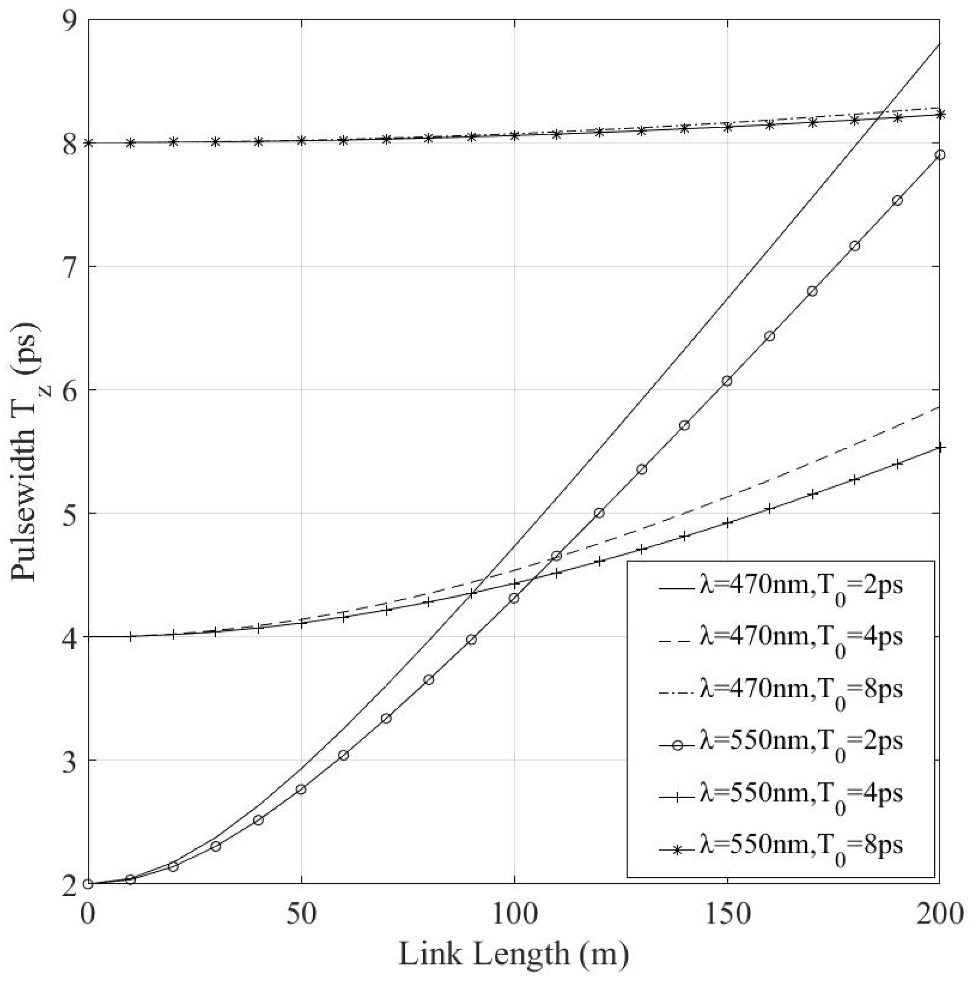
Figure 1. Pulsewidth of an unchirped pulse versus propagation distance for various wavelengths and initial pulsewidths.
Computation 07 00035 g001
Figure 2. Pulsewidth versus propagation length for various initial pulsewidths and chirp values.
Computation 07 00035 g002
Figure 3. Maximum bit rate, Rmax, as a function of the propagation distance for various cases of input pulsewidth and chirp at 50 m depth.
Computation 07 00035 g003
Figure 4. Probability of fade as a function of the propagation distance for various cases of input pulsewidth and chirp with fixed irradiance threshold; Ith = 1 × 10⁻¹⁰ and variance σT = 5 ps.
Computation 07 00035 g004
Figure 5. Probability of fade as a function of the propagation distance for various cases of input pulsewidth and chirp with fixed irradiance threshold; Ith = 1 × 10⁻¹⁰ and variance σT = 10 ps.
Computation 07 00035 g005