Abstract
In this study, we study the trapping of linear water waves by infinite arrays of three-dimensional fixed periodic structures in a three-layer fluid. Each layer has an independent uniform velocity field with respect to the fixed ground in addition to the internal modes along the interfaces between layers. Dynamical stability between velocity shear and gravitational pull constrains the layer velocities to a neighbourhood of the diagonal in velocity space. A non-linear spectral problem results from the variational formulation. This problem can be linearized, resulting in a geometric condition (from energy minimization) that ensures the existence of trapped modes within the limits set by stability. These modes are solutions living the discrete spectrum that do not radiate energy to infinity. Symmetries reduce the global problem to solutions in the first octant of the three-dimensional velocity space. Examples are shown of configurations of obstacles which satisfy the stability and geometric conditions, depending on the values of the layer velocities. The robustness of the result of the vertical column from previous studies is confirmed in the new configurations. This allows for comparison principles (Cavalieri’s principle, etc.) to be used in determining whether trapped modes are generated.
1. Introduction
In the context of linear water wave theory, edge waves or trapped modes are non-trivial solutions in the frequency domain of the Laplace equation. These modes refer to time-harmonic oscillations of radian frequency and of finite energy that occur within a fluid medium. They can be defined as free oscillations of a fluid that possesses finite energy and which does not radiate energy to infinity. These modes are distinct from standard propagating waves. In the absence of viscosity, they can persist indefinitely over time [1,2]. Their existence is contingent upon the presence of cylindrical structures of infinite extension or of an endless periodic array of similar obstacles, which may include both fixed structures and freely floating bodies. These modes become confined in the vicinity of these structures, preventing them from dissipating their energy to infinity.
Trapped modes are particularly significant in the study of water waves as they imply non-uniqueness in the solutions to radiation and diffraction problems associated with the mentioned structures [3]. The modes can be categorized into two types: sloshing modes, which occur in fixed structures and motion-trapped modes, which arise in freely floating structures where the fluid and structure oscillate in a coupled manner [2,4]. The mathematical formulation of trapped modes often involves spectral boundary-value problems, where these modes are identified with eigenvectors of the operator whose eigenvalues live in the discrete spectrum situated below a positive lower bound of the continuous spectrum. Occasionally, they may also exist above this bound, earning the designation of embedded eigenvalues in the continuous spectrum [5].
The interaction of trapped modes with wave phenomena is not limited to static structures. Freely floating structures can also support trapped modes through a coupled motion of the fluid and the structure. McIver and McIver [2] highlighted that, in two-dimensional scenarios, such modes can persist even when the structures are allowed to respond dynamically to hydrodynamic forces. This dynamic interaction is crucial for understanding the broader implications of trapped modes in practical applications, such as marine engineering (e.g., designing marine structures) and the analysis of wave energy converters or wave energy harvesting.
In 1846, Stokes’ solution for an edge wave along a coastline, later identified as a trapped wave, marked an early milestone [6]. Ursell [7] significantly advanced this understanding in 1951 by conceptualizing trapped modes as discrete spectrum modes within surface wave theory. He established that a free surface extending infinitely in a fixed direction would yield solutions with two distinct characteristics: modes with finite total energy that is preserved and modes with infinite total energy that is radiated to infinity. Ursell’s initial exploration of these modes included examining their existence conditions in two configurations: a sloping beach with a constant angle and a submerged circular cylinder in a channel perpendicular to the channel walls. Later studies, focusing on motion in a semi-infinite channel with a sloping beach, revealed a mixed spectrum with both discrete and continuous components [8].
Significant developments in the study of trapped modes include Fritz John’s establishment of uniqueness conditions for surface-piercing bodies [9], as well as Simon and Ursell’s extension of these uniqueness conditions to bodies that do not satisfy John’s geometrical criteria [10], including multiple-body systems. Evans et al. [11] derived trapped mode solutions in channels with constant depth containing a vertical, surface-piercing cylinder. McIver [12] analytically and numerically demonstrated the existence of a trapped mode solution in the two-dimensional water wave problem, with similar numerical analyses conducted by Evans et al. For a comprehensive review, see Kuznetsov et al. [13] and Linton and McIver [14].
While early research primarily concentrated on single homogeneous fluid layers, the exploration of trapped internal modes in multi-layered fluids began with Kuznetsov’s work on trapped modes above a submerged cylinder in a two-layer system [15]. Subsequently, Linton and Cadby [16] computed trapped modes in configurations involving circular cylinders submerged in either the upper or lower layer of a two-layer fluid. Their research extended to investigating modes generated by a pair of identical circular cylinders situated in the bottom layer. Notably, the trapped modes identified in these studies were found to reside within the continuous spectrum, rather than the discrete spectrum.
The work of Kuznetsov et al. [17], extended Maz’ya’s identity to two-layer fluids, proving crucial for establishing the uniqueness of specific body configurations in two dimensions. This identity was further extended to three-dimensional configurations by Cal et al. [18]. Building upon the work of Kamotskii and Nazarov [19], Nazarov and Videman [20] introduced a sufficient condition for the existence of trapped modes using a trace-interface operator, which restricts solutions to the free surface and the interface. This method, employed in numerous studies (e.g., [21,22,23]), has been further generalized for quasi-periodic artificial Dirichlet conditions to ensure a positive cut-off for the continuous spectrum [5,24,25]. This generalization extends the analysis beyond cylindrical problems and symmetry constraints (see [26,27]). Fluid stratification due to variations in temperature and/or salinity is common in oceans, leading to the formation of distinct homogeneous layers. Internal soliton-like waves within these stratified layers can create noticeable patterns on surface waves traveling above them. Notably, the potential-flow formulation connects the surface modulation of waves to trapped modes (or bound states) of the associated linear Schrödinger operator (see [28] and its references).
The investigation of sufficient conditions for the existence of modes within the discrete spectrum has predominantly centered on static configurations of single, two, or multiple fluid layers (see [5,19,21,22,23,24,25]). The pioneering work on stationary moving configurations in fluid dynamics was first introduced by Dias [29], which laid the groundwork for understanding how fluid motion, particularly due to currents and tides, influences the presence of trapped modes. This is especially pertinent in real-world applications, where the dynamics of fluid motion are critical for the design and establishment of marine structures and the overall energy flow in oceanic and riverine environments [30]. For instance, when analyzing a single layer of fluid with velocity, the methodology typically involves a transformation of the reference frame, allowing for the application of established formalism [29]. In the current study, we extend this analysis to a three-layer configuration of an unbounded fluid with two interfaces. This extension is particularly significant given its numerous practical applications in various fields, including environmental science and engineering. The dynamics of such layered systems can reveal intricate interactions between fluid layers, which are crucial for understanding phenomena like wave propagation and energy transfer in stratified fluids.
The structure of this paper is detailed as follows. In Section 2, we establish the standard notation and present the fundamental problem within a periodicity cell, adhering to the conventional assumptions of linear water-wave theory. In Section 3, the model problem in the periodicity cell without obstacles is solved, wherein we ascertain the corresponding eigenfunctions and eigenvalues, as well as the cut-off value of the continuous spectrum. Moreover, the stability condition is derived, allowing us to delineate the velocity domain pertinent to our analysis. In Section 4, we investigate certain limiting cases. The problem is reformulated in a more simplified manner in Section 5, incorporating additional assumptions regarding the steady background flow. Section 6 introduces the variational and operator formulations, alongside the surface–interface trace operator. To ensure a linear problem in relation to the spectral parameter, a necessary approximation is made. In Section 7, we derive a sufficient condition and state our main results. Section 8 provides a comprehensive analysis of the various symmetries inherent in both the obstacle-free and obstacle-inclusive problems within the velocity space. In Section 9, we present illustrative examples of structures that generate trapped modes, initially recovering the results pertaining to the vertical uniform column for moving layers, and subsequently employing comparison principles, such as Cavalieri’s principle, to derive further insights. We then present a more general example, comparing the setup with a similar analysis in [29]. Finally, some conclusions are drawn in Section 10. All units are SI. The gravity field strength is .
2. Formulation of the Problem
Consider an incompressible, inviscid fluid lying in three horizontally infinite, homogeneous, and immiscible layers stacked vertically. The top layer is semi-infinite in the vertical direction () and is separated by an interface from the middle layer, which is vertically finite. The bottom layer is in turn separated from the middle layer by another, lower interface and is semi-infinite in the negative vertical direction ().
For gravitational stability, we assume that the constant density in the lower layer exceeds the one in the middle layer and that the latter exceeds the density in the top layer, i.e., , and suppose that the flow in each layer is irrotational (see Lamb [31]).
The interfaces are infinitely thin and there is no intermediate layer due to viscosity, which is assumed to be non-existent. There is an infinite velocity gradient crossing from one layer to another. Due to the density difference between layers, because of the necessary gravitational stability, there is a domain for the mode velocity propagating along the interfaces, called internal modes, which allows for dynamical stability, which would be immediately lost if the densities became equal and the interfaces were simply velocity discontinuities [32]. This is a good approximation to many multilayer configurations found in the oceans and the atmosphere, and it allows to approximate fluids of continuously varying densities without having to forego the potential flow approximation layerwise.
Cartesian coordinates are fixed at middle depth of the middle layer, with the plane placed at the mean position of the latter and the z-axis pointing upwards. Submerged in the fluid domain rests a periodic array of finite, fixed, and rigid obstacles extending to infinity in the y-direction. Time-harmonic waves of radian frequency propagate along the array in the y-direction. Each layer has a constant velocity component in the y-direction, denoted by , , and , respectively.
The fluid domain is divided into periodicity cells, each of them extending to infinity in the x-direction, having finite length in the direction and containing the same obstacles. The fluid layers are denoted by , and , and the model periodicity cells in each layer, in the absence of obstacles, are denoted by
Moreover, we use and to represent the top and bottom interface between the two layers in their instant positions, respectively, i.e.,
The top and bottom interface surfaces are given by the functions and , respectively, which are taken to be a small oscillation (compared to the wavelength) around and , their mean positions. Note that at the middle of the middle layer (when considering the mean positions of the surfaces); thus, the mean height/depth of the interfaces is symmetric, with the first interface at and the second at .
Within the fluid layers, we introduce bounded open sets , , and corresponding to the submerged part of a model obstacle and assume that the fluid regions
are Lipschitz domains so that the normal vector is defined almost everywhere on , and . We also define the surfaces (Figure 1)
and denote the unpierced parts of the free surface and interface by and , i.e.,
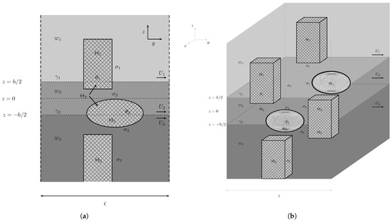
Figure 1.
(a) Model periodic cell with general fixed obstacles and a (b) 3D scheme of the periodic array of the obstacles.
Under the usual assumptions of the linearized water wave theory, we introduce single-valued velocity potentials in each fluid region and look for trapped mode solutions of the format
These solutions are the sum of a time-harmonic oscillating solution, with time dependence of the form , assumed throughout, and an additional potential representing a steady background flow, which is a given of the problem. This flow is given in each cell in such a way that
where is the distance to the nearest fixed obstacle inside each cell and is a set distance relative to any obstacle boundary , dependent on the cell configuration and the relative size of the obstacles. The function describes the steady flow in the vicinity of the obstacles, with for . The oscillating modes propagate along the periodic family of obstacles but decay away from them and the periodicity suggests us to seek the velocity potentials in the form (see Wilcox [26])
where , the wavenumber in the direction of the line of obstacles, is assumed to be real and positive.
This is a problem of small oscillations around a steady-state motion, where we look for a velocity potential describing such waves traveling along the periodic array of fixed obstacles on top of an undisturbed steady state. Both potentials, and describe potential flow. They must each independently satisfy the Laplace equation. This leads to the following problem in the model periodicity cell:
where is the time-harmonic radian frequency, is the acceleration due to gravity, , and , with n denoting the outward normal vector (pointing into the obstacles). The condition of no-flow on the surface of the obstacles, (4g) and (4h), must be obeyed independently by the two motions. Observe that the quasi-periodicity conditions in (4i) guarantee that the velocity potentials satisfy the problem in the entire domain and extend smoothly from cell to cell. The conditions for the steady flow assure that it is defined universally. The momentum boundary conditions (4c) and (4e) stem from equating the pressures on each side of the interfaces, using the time derivative of the linearized Bernoulli equation in each layer. The kinematic conditions (4d) and (4f) are derived from the no-mix condition at both interfaces, where we impose, say, to first-order approximation (see, e.g., [33]).
3. The Problem Without Obstacles
Due to the fact that the array of obstacles acts as a compact perturbation, the spectral structure of the problem with obstacles is the same as the spectral structure of the problem without them. This stems from the Weyl theorem on operator perturbation [34]. We can determine the threshold between the essential and discrete spectra (which live on the real line) from the condition that the solutions be non-trivial. This is obtained from the real solutions with unitary multiplicity. The lowest absolute value of in any neighbourhood of the velocity space (with so that there is no propagation in x to infinity) is this threshold value in that neighbourhood.
Let us consider the problem in the periodicity cell in the absence of obstacles, where in all space, . This problem is analysed in a linearised form, such that all terms in the equations above, which are products between functions or derivatives of functions, are discarded. For example, the quadratic terms in (4c) and (4e) will be reduced to . The above boundary conditions will be rendered in the following manner
where the evaluation is made at the mean depth of the free surface and interface.
A solution , plus and , of the form
is given, with , , the wavenumber in the y-direction, and , and as the layer velocities along y. This solves the Laplace Equations (4a) and (4b). The boundary conditions and the asymptotic conditions imply that and the wavelike solutions to problem (4a)–(4j) without obstacles become (ignoring the fixed velocity layer terms)
The boundary conditions at both interfaces yield the following dispersion relation (making and ):
The dispersion relation is a sixth-degree equation for . One immediately discards a global term, which means that is one of the roots of the sixth-degree polynomial, with multiplicity of two. This is a solution of no mode propagation and is discarded from our analysis. The remaining solutions for Equation (7) are , with .
The Kelvin–Helmholtz instability results from the velocity shear that is created by the velocity difference between two layers at an interface, where an infinite velocity gradient exists if the viscosity is null (Figure 2). This difference creates a pressure imbalance that—according to Bernoulli’s principle—causes a disturbance which is resisted by gravity if the lower layer density is larger than the upper layer density ( guaranteed by the initial assumption of gravitational stability. Any flow differences will help increase this disturbance. Viscosity, here absent, creates a boundary layer that creates a velocity continuity. In our approximation, since viscosity and surface tension are assumed to be zero, only gravity is a deterrent. Therefore, any increase in velocity difference increases instability. After a certain gap, instability grows exponentially. That is what these conditions show: the interval in velocity difference before disturbances grow without gravity being able to stop them. Since the middle layer creates a link between the lower and upper layers, their velocity differences become also relevant, since it is the middle velocity that anchors both the upper and lower velocities. Since we want to avoid the Kelvin-Helmholtz instability (see, e.g., [32] or [35,36]), the solutions have to be real. If the solutions are complex, the phase will be exponentially increasing or decreasing; this means that there will an increase in the wave. The condition for this is the combination of the following three inequalities (see, e.g., [37]),
where the discriminant and the following functions are functions of , with , and .
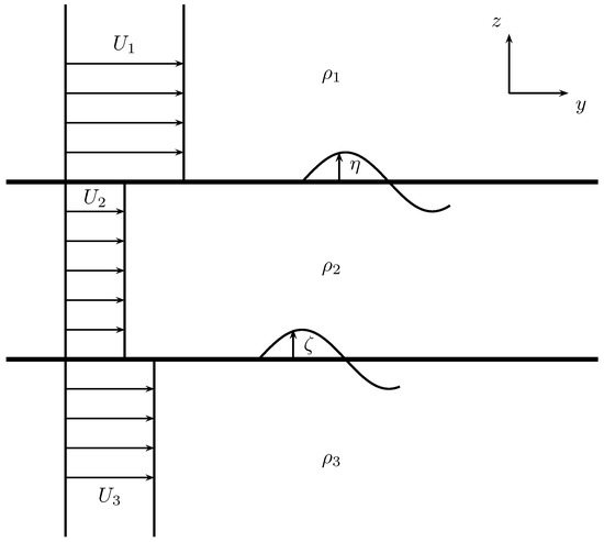
Figure 2.
Schematic of the Kelvin–Helmholtz instability in the three layer configuration.
Of the three conditions above, is the more stringent, which means that the intersection of all three is just the first. The condition implies that the four real solutions are different, with a multiplicity of one. Real solutions with higher multiplicity would imply that , which defines a line boundary in the velocity domain. Those solutions at the boundary represent borderline situations that separate the domain with only real solutions from the domain with complex solutions. Complex solutions imply exponential instability in the velocity potential solutions, leaving the domain of applicability of the chosen equations. We focus our attention thus on real solutions of multiplicity of one (, , and ) (see Figure 3). They are ordered as .
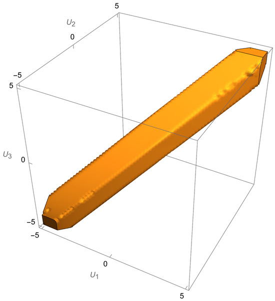
Figure 3.
Region of stability with parameters , , , and .
If we add the same general speed to , , we find that
The smallest solution (in modulus) of the four is a relative concept. The addition of any real value to all of the layer speeds simultaneously is the same as moving in velocity space from a chosen initial point along a line parallel to the vector , that is, . This indicates one of two things: (a) changing the referential of the observer or (b) adding global speed to the layers relative to a chosen referential. Later, we will see that the preferred referential is that of the fixed obstacles. Along any line in the direction contained in the stability domain each smallest solution is the one closest to zero in different intervals along that line. In ascending order, the smallest value (in modulus) of will thus be (see Figure 4).
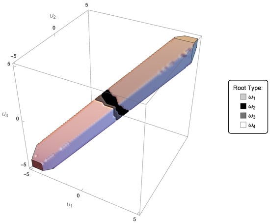
Figure 4.
Region of stability, with parameters , , , , coloured according to which of the is the . Note that the colours code each value of .
There is an additional property of the solutions. If one makes , one finds that
From the graphic depicting an example of a stability region in velocity space (see Figure 4), the border between the regions where and are the closest to zero, in other words, where each is , is approximately a plane passing through the origin. The above symmetry, Equation (10), allows us to choose then effectively only one half-space to solve the entire problem. Since we can work only in half of the entire velocity space, we choose the top-right half encompassing the first octant (where ). The closest solutions to zero will then be mostly and . In each respective domain, that solution is the one whose value is the smallest of the four. This solution evaluated as is then defined, for that domain, as , with , for . In each of these domains, changes sign (from to ), all along having the smallest value of , thus being (see Figure 5).
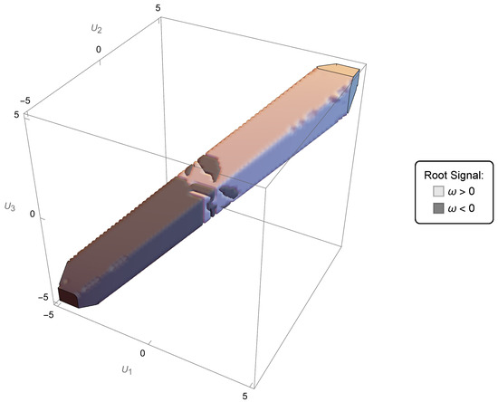
Figure 5.
Region of stability, with parameters , , , , coloured according to the sign the respective . In each domain where , is smallest, and it has a subregion where it is negative and another is positive.
By cutting a section along the axis , we recover a band such as the one obtained for the stability region in the cases of two layers, both the one without an upper boundary and the one with a free surface (see Figure 6 and [29]).
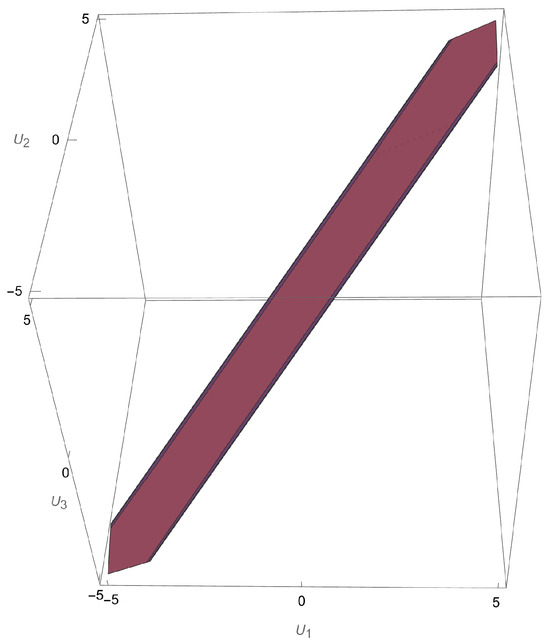
Figure 6.
Section of region of stability along , with parameters , , , . One recovers the same band as in the two-layer cases, both semi-infinite and with a free surface.
The spectral parameter will be . Therefore, defining ,
Working in the half-space chosen, we have
in the respective domain where and are . The non-trivial solution corresponding to is, up to multiplication by an arbitrary non-zero complex constant,
where
The coefficients are equal to
Note that the terms of the form are invariant under .
Remark 1.
If one tries to study the equivalent system for an upper layer topped by a rigid lid and a flat finite bottom below the third layer, one will still be able to use the approximation of infinite top and bottom layers before seeing any relevant differences in both stability and sufficient condition. In fact, if we choose as layer thickness both for the top and lower layers 0.25 of the middle layer, there is no significant change in the essential results: stability has the same region, with slight modifications, and the sufficient condition is barely affected. Therefore, we will stick to the infinite layer approximation throughout.
4. Limiting Cases
4.1. and
We intend to take the density of the top layer to naught. The resulting system is a two-layer fluid with a free surface over one finite layer with an interface over a semi-infinite layer. Ignoring the global factor, which was discarded above, the resulting dispersion relation is then
with the respective discriminant being a rather cumbersome expression of the parameters. The stability condition (demanding that the solutions be both real and distinct) is . This is shown in Figure 7. It is the projection of the general region in Figure 3 onto the plane in velocity space, where .
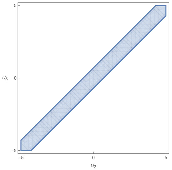
Figure 7.
Stability condition from the limit and .
This limiting dispersion relation is, however, different that of the two-layer system with a free-surface calculated directly in the same way as above. The latter is given by the following expression (again ignoring the global factor):
Although qualitatively similar, the dispersion relations are not equal: the discriminant is different and therefore the stability condition is also different. This shows that one cannot directly, from this limiting procedure on the dispersion relation, obtain a two-layer setup with a free-surface. Although one would physically expect that the limit above would result in a two-layer fluid of one finite layer on top of a semi-infinite layer, mathematically the dispersion relation that comes out of the limiting procedure is not the one obtained directly from the analysis of an identical configuration. This shows that great care should be taken when calculating a limit in the mathematical description of physical systems.
4.2. , and
In this case, the limit reduces the middle layer to the top layer, making the system a two-layer system with semi-infinite layers, as in [29]. The dispersion relation is
There is an immediate solution in with a multiplicity of two; this discriminant is then null. We have to keep all the terms to be consistent and with it conclude that the limit is unstable. If we discard the first factor and just leave the remainder of the left-hand side of the equation (only the second parenthesis with a quadratic expression) equal to zero, we find the respective discriminant to be
This results in a condition for the existence of real and distinct solutions given by . From this discriminant, the region of stability has width
A graphical depiction is given in Figure 8. It is again a projection, this time of the general region in Figure 3 onto the plane in velocity space.
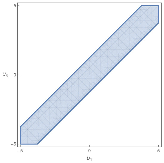
Figure 8.
Stability condition from the limit , and .
This result is, however, as above in the previous limit, not the one obtained from the previous analysis in [29]. This again shows that one cannot directly, from this limiting procedure on the dispersion relation, obtain the two-layer system studied in [29]. Physically, if one takes the limit above, one should realistically recover the setup of two semi-infinite layers one on top of the other. However, since we are starting from a configuration of three layers, it is perhaps natural to assume that the making of both densities equal may add instability to the system, since the density difference is now null. But once we make the densities and the layer velocities equal, for purposes of mechanical behaviour, the two layers become one and one does not describe a given layer of a homogeneous fluid as intrinsically unstable. This poses the question of the physical meaning of such a limiting procedure.
4.3. , and
This case is like the previous one, but instead of approximating the middle layer to the top layer, we approximate it to the bottom layer. The dispersion relation is
Again, there exists a term which has a possible real solution with a multiplicity of two, . This implies instability because we have . Ignoring the first factor, the remainder of the dispersion relation has as the respective discriminant the same expression as in the previous subsection, with the resulting condition being identical to the previous one.
4.4. and
Here, the limiting procedure results in
In this case, we also find a solution with multiplicity of two. However, since the solutions of zero frequency are discarded, as was performed in [29], we could drop the question and concentrate our analysis in the remainder of the expression. This part is equal to the last two cases above. We have the same discriminant and the same region of stability as in Figure 8. However, and here with more relevance, the resulting dispersion relation is different from the one in [29]. The limiting procedure yet again does not recover the dispersion relation of the expected limiting setup.
4.5.
It is not reasonable at first sight to consider this limit, but for purposes of understanding, we show it here. It is in fact the one with the greater simplicity. The resulting dispersion relation is simply
We have two complex conjugate solutions plus two real solutions of multiplicity of one since the discriminant
is clearly negative. This expression for the dispersion relation does not, despite the stability condition and its simplicity, coincide with the one obtained if one starts from scratch assuming the limit (as was performed in [29]).
The general conclusion is that simply making the limit from the dispersion relation does not recover the simplified system intended with the limiting procedure.
5. The Equations in the Limit of
We are now going to assume that the layer speed in each layer is such that we can reduce to a small quantity, reducing to a negligible volume the layer around the obstacles where the velocity potential is given by . In the following, we therefore assume . More generally, for ,
We will discard terms such as but not terms such as . Assuming the general format of the solutions in Equations (6a)–(6e) and rewriting the equations of motion with the above approximations, we obtain the first term of the Taylor expansion for the linearised Bernoulli equation at the first interface (about ) and at the second interface (about ) (see [33])
The linear interface kinematic conditions for the potentials stem from the material derivative (to first order in Taylor about ). Thus, for the first interface
Using
we obtain the kinematic conditions (about ) as
Using the ansätze in Equations (6a)–(6e), we see that, for the first interface,
where . From (35), we obtain the following boundary condition
If we make the following renaming
where are Doppler factors, we arrive at
Neglecting the interface function , the equations for the interface can be then reduced to the following two
In the same vein, on the second interface we find
where we can ignore the function . The remainder equations can be straightforwardly applied to the primed potentials.
Remark 2.
If , one of the layer speeds is equal to the mode speed. This is a degenerate case, which is in effect tantamount to making . The equations at any one of the interfaces become, when , that is, when the upper layer has the same speed as the mode,
and
Equation (44) is analogous to that of the free-surface (when there is one), with . If we make , we have the same equation which is obtained for the free-surface by assuming that the air density is zero, . If instead we make , i.e., the lower layer has the same speed as the mode, then
This is not in the form of a free-surface momentum equation and the analogy breaks, unless , but in this case, the stability condition is not respected. From this, we assume throughout that , for . However, at the end, the variational formulation can be extended by continuity to the case of , (see also the discussion in the previous section).
6. Variational and Operator Formulation
Let us multiply the Equations in (4a) and (4b) by test functions , where denotes the space of infinitely differentiable functions with compact support in , satisfying the Dirichlet quasi-periodicity condition, that is, the first equation in (4i); we then integrate in the fluid domain the sum of both equations (in each layer) and sum the contributions of the two layers together.
Remark 3.
Test functions of compact support , , satisfy by construction the Sommerfeld radiation condition. That is why the terms at infinity are of no consequence in the following integrations [38].
The domain enveloping the obstacles and contained within the distance around each obstacle is denoted by and is limited by the boundaries , , and (where appropriate), is an artificial boundary at , and the functions cross smoothly from one domain to the next. The above sum is therefore
After integrating by parts, using the boundary conditions in (4g) and (4h), plus the natural continuity across the artificial boundary , which cancels the contributions on this boundary, and invoking the limit , this sum becomes
Ignoring quadratic terms, the normal defined on the first interface is downward pointing looking from the first layer and upward pointing looking from the second; the normal defined on the interface is pointing downward from the perspective of the second layer and the opposite to that of the third, that is,
For the first interface, using Equation (34), we obtain
From the boundary conditions (39) and (40), we draw
The same happens for the second interface,
In the end, we obtain, for the whole configuration, the following variational formulation:
We note that (to first order) the directional derivatives of the primed potentials are the same as the derivatives of the complete wave plus background potential above (see (50) and (51)), to the effect that
This means that we can rewrite the variational formulation in (54) as the primed potential variational formulation
The term coming from the background flow potential is a given of the problem, it is not a variable. This means that the background kinetic energy is not relevant to the variational formulation since it is always the same. The trapped-mode problem is about the energy of the oscillating mode, which is superimposed onto the steady background flow. The variation in energy, and not its full content, is what is relevant, in much the same way as the gravitational potential energy is always determined up to a constant, implying that the difference in potential energy and not its absolute value is what is relevant (within the bounds of the linear approximation). It is therefore natural to expect that, in this approximation, the two approaches (54) and (59) are equivalent.
The expression in (59) is not symmetrical under . Introducing the primed potential
into (59), and also changing the test function from to , we obtain
The right hand side is now symmetric under . By eliminating the redundant primed terms
we arrive at the variational formulation of our problem.
Let , be a subspace of satisfying the Dirichlet quasi-periodicity condition, i.e.,
and let and denote the scalar products in the Lebesgue spaces and , respectively. Morever, let be the function space of elements , equipped with the scalar product
Note that the quasi-periodicity condition ensures that non-zero constants cannot belong to . The variational formulation of (4a)–(4j) consists in (see [39]) finding a non-trivial and such that for all
It is clear that we cannot define a linear spectral problem when the parameter is , if at the same time there is in the definition of . An approximation is warranted if the formalism is to be of use. The general method followed (see, e.g., [20]) is to perturb the solution on the threshold of and from the compact perturbation obtain a relation that is sufficient to guarantee that the discrete spectrum of the problem derived from the initial equations is non-empty. This means that the relevant functions in the appropriate space are all close to , meaning that their associated mode speed is close to . This suggests the approximation , with . Therefore, in the following, the are all and the speed in the Doppler factors is . All function spaces below will then be assumed to be subsets of the designated spaces of functions, with mode speeds in the neighbourhood of the mode speed of .
Let us introduce a trace–interface operator by the formula
The operator T is continuous thanks to the trace inequality (see [40])
With the help of operator T, the spectral problem (4a)–(4j) can be written as
where is a new spectral parameter. The continuous spectrum of T, , is determined by the continuous spectrum of the problem (4a)–(4j) without obstacles. The latter lies on and thus , with . Given that is an eigenvalue of infinite multiplicity with the associated eigenspace
the essential spectrum of T is .
Now, the operator T is positive, continuous, and symmetric; therefore, it is self-adjoint (note that are assumed). Its spectrum lies on the interval of the real axis in the complex plane with denoting the operator norm of T and its discrete spectrum. For the discrete spectrum, there are two possibilities: either the norm of the operator T coincides with , i.e., , so that the discrete spectrum is empty, or and the discrete spectrum is non-empty, since (see Birman and Solomjak [41]).
7. A Sufficient Condition for the Existence of a Trapped Mode ()
Recall the definition of an operator norm
and consider a function defined by , where is the solution associated with the cut-off value (see (13) and (14)) and is a small positive parameter. It is easy to see that , so that we can estimate the right-hand side in (64) from below using as a trial function.
Using to represent the part of the surface pierced by the obstacles, i.e.,
we obtain
where we have used the approximation in the compact sets .
Similarly, we obtain
where we have used integration by parts and observed that is a solution to problem (4a)–(4j) without obstacles, and thus
On the other hand, by making use of the boundary conditions (4c)–(4h) for ,
we write
This allows us to conclude that
To simplify the presentation, we define
and let and . It follows that
Next, let us analyse under which condition, if any, the norm is greater than the threshold value . Since , we obtain in view of Equation (75)
where denote some positive constants. Hence, if
there exists such that the norm is greater than for all .
Theorem 1.
Corollary 1.
Any array of obstacles with non-zero volume, not piercing any of the interfaces (in this instance always submerged in each layer separately), generates a trapped mode.
Proof.
We have and in (76). The condition is immediately met. □
Remark 4.
We do not consider the case because it brings no further profit for the purpose of the present work. In any case, it is straightforward to generalise to this case proceeding as above in the corresponding section in [24].
Remark 5.
From the formula for P above (Equations (72) and (73)), one sees that the are Doppler terms, in that they modify the term of the sufficient condition due to the velocity of the layers. In fact, if a wave source (wave speed ) is moving with respect to a receiver with speed , the change of frequency arriving at the receiver is going to be
with ω being the frequency at the source. The minus sign applies to when the source is moving away from the receiver and the plus sign to when the source is moving towards the receiver (see, e.g., [42]).
In general, and one can make , independently without any illicit result showing. However, if , then , which renders the sufficient condition void. This is tantamount to having a mode velocity equal to a common layer velocity. In this situation, there is no mode relative to the layers.
Theorem 2.
The sufficient condition (76) is invariant under , for all .
Proof.
The dependence on the velocity is given by terms of the form . In the case of the volume integrations in V, these show up in the function coefficients (15)–(20). In the case of cross-section integrations in , they show up in addition in the products . All these are invariant under , . The conclusion is direct. □
Corollary 2.
Any triplet of velocities , , and can be taken into the first octant in the velocity space by a general translation of an added global velocity . From Theorem 2, we can consider only the case of , , without loss of generality. The first octant is therefore all that it takes to determine the full results for the entire velocity space.
8. Symmetries
It is important to understand the symmetries of the system before moving on to the examples.
8.1. Problem Without Obstacles
The general problem without obstacles has two symmetries in the velocity space:
- Under , , the solutions of the dispersion relation change as , , where ;
- Under an inversion of the layer velocities , we find that the solutions of the dispersion relation become the symmetric of the ones before the inversion. Of course, (therefore also ) is invariant under this inversion. This means that one can divide the velocity space into two, since if one solves the problem for a pair , one also solves for the symmetric . This is simply a left–right invariance in the general direction of the flows.
8.2. Problem with Obstacles
The problem with obstacles inherits properties of the free problem. These are reflected in the sufficient condition, which is invariant under
- , , and
- .
The sufficient condition is an energy condition, and therefore dependent on the square of the speeds, which means that it is left–right symmetric from its inception.
8.3. Distinctions
When there are no obstacles, adding means two things that result in the same: (a) adding a common speed to the fluid with respect to the observer or (b) the motion of the observer is such that in his reference frame the fluid layers have an increase in their speeds of . Either way, the dispersion relation solutions are changed by the same amount, such that . This, however, means that the lowest may change with , implying that to obtain one must not simply add to , but ascertain which one of the new solutions, after has been added, is now the smallest in absolute value. For example, if before , now it may happen that .
If, however, we add obstacles to the problem in order to obtain a sufficient condition for the existence of trapped modes, (a) and (b) are not the same. Option (b) does not change the problem; it only adds to the relevant quantities and, more importantly, does not change , except through for the observer. This is because of the change in speed of the obstacles, which now move with respect to the observer. The motion of the layers with respect to the obstacles has not changed and the smallest with respect to the obstacles is the same, implying that is the same. This is reflected in the invariance of the sufficient condition. Option (a), on the other hand, changes the sufficient condition. If a common speed is added to the layers with respect to the obstacles, then the smallest may change, because now the mode speeds have changed with respect to the obstacles. Although the sufficient condition seems to be invariant under the addition of , now one must make sure that the correct (or ) is used in the sufficient condition expression.
It is now evident that in each domain of the velocity space where does not change (except through ), the properties in Section 8.2 above are still valid. However, if a speed addition changes the solution of the smallest absolute value, then the sufficient condition is no longer invariant under global velocity changes.
In the examples below, the allowed domain (velocity space) will be the intersection of the domain delimited by the stability condition and the domain given by the sufficient condition, with different pockets for different , determined by the smallest of the .
9. Examples
9.1. Column of Uniform Cross-Section
In this example (see Figure 9), we apply the sufficient condition to the paradigmatic setting of a vertical column that crosses all domains and all boundary surfaces between layers. In this case, a vertical column that stretches from to and crosses both and .
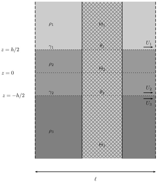
Figure 9.
Column with uniform cross-section.
Applying Formula (76) directly, we find that
The integrand funtions do not depend on x or y, so the term is common to all. It can be discarded from (77), and the latter becomes
Integrating by parts in z and rearranging terms such that the boundary conditions (65)–(70) can be directly applied, we find that the previous expression can be rendered as
It is thus proven that for a vertical column. We will from now on designate the terms related to the vertical column as and , thus . By a straightforward generalization of the proof found in [19,20,43] (see also in [24]), we can show that the vertical column generates trapped modes.
9.2. Obstacles That (Almost) Always Satisfy the Sufficient Condition
In Figure 10, the configuration on the left results in
because . For the one in the centre, we have a simple application of Corollary 1 due to the fact that , for . Both results are immediate. For the obstacle on the right, we have two positive parameters and , which will determine whether the condition is met. If we fix a small enough , there is a threshold such that
In that case, if , the sufficient condition is met and if the sufficient condition is not met. However, if is such that even in the limit , still excluding , we find . Then, in that case ; thus, the sufficient condition can never be met. The same applies with the roles of and reversed. In both examples, there is a finite distance between the obstacle and the interface, such that in that interval the sufficient condition is met. Therefore, this configuration allows, given an appropriate distance of the obstacle from the interface, the attainment of the sufficient condition. The situation would be the same if the gap had been designed astride the first interface instead of the second.
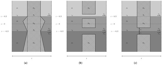
Figure 10.
Obstacles that satisfy the sufficient condition by comparison with the vertical column of constant cross-section. The first two (a,b) are always satisfied; the obstacle on the right (c) is satisfied only if and are such that the sufficient condition is met.
9.3. Obstacles That Never Satisfy the Sufficient Condition
In Figure 11, all instances have and . This implies that
It follows that these obstacles do not satisfy the sufficient condition.
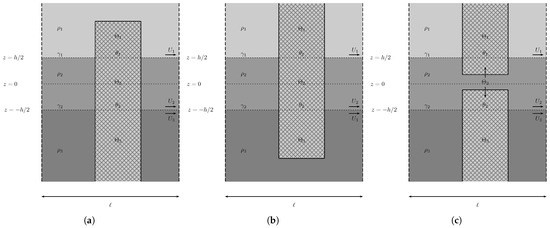
Figure 11.
Obstacles that never satisfy the sufficient condition by comparison with the vertical column of constant cross-section. In (a) the missing volume in makes , in (b) the same happens now with , and in (c) the same with .
9.4. Cavalieri’s Principle
In the configuration shown in Figure 12, we find that the integration of (78) is the same, despite the change of domain , . This is the application of Cavalieri’s principle, that states that two objects situated between two parallel planes have equal volumes if, for every respective cross-section situated between these two given planes, the areas of the former are equal. Simply stated, any horizontal translation of sections of the obstacle that keep the cross-sectional areas changes nothing. Thus, this example repeats the result of the vertical column.
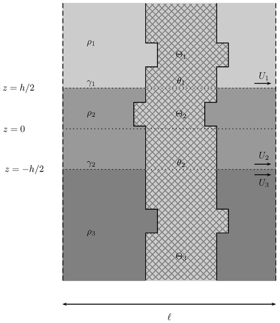
Figure 12.
Obstacle that satisfies the sufficient condition by comparison with the vertical column of constant cross-section using Cavalieri’s Principle.
However, for the configurations in Figure 13, the expression in (77) does not reduce to (78), hence Cavalieri’s principle is no longer valid. In general, a conclusion is not possible. However, in these two instances of Figure 13, we can obtain a result due to the monotonicity of the respective functions .
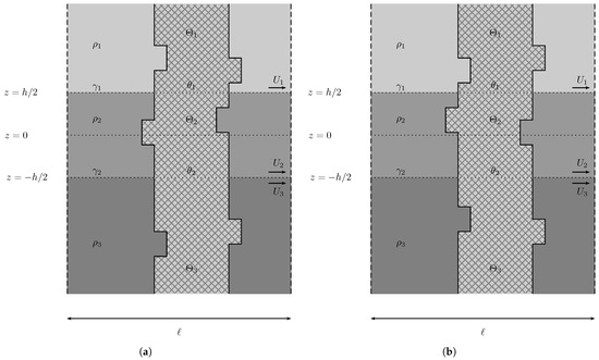
Figure 13.
Obstacles that cannot be directly compared with the vertical column using Cavalieri’s principle. On the left (a) one can prove that trapped modes are generated, whereas on the right (b) no such proof is forthcoming.
In fact, the volume of the depicted obstacles is the same as that of the vertical column. On the left of Figure 13, the example is that of a volume closer to the interfaces in both the first and third layers, whereas on the right the volume of the column has been translated a little further away, again both in the first and third layers. Both cases are outside the scope of Cavalieri’s Principle. Let us assume, for the moment, that both configurations (left and right) have . In the top (or first) layer we have and in the bottom (or third) , such that the integrand of (77) is monotonically decreasing away from the interface. Therefore, the integration of (77) on the left is larger than and the one on the right is smaller than . Since , we have that on the left and on the right . We can infer that the left configuration of Figure 13 produces trapped modes, whereas we cannot conclude anything about the configuration on the right.
Let us now assume that . If , then we have to verify case by case whether the change on the left satisfies the sufficient condition, since both and are larger than their starred counterparts. The configuration on the right, which already did not satisfy the sufficient condition when , is now further from satisfying the condition. If, on the other hand, , then the configuration on the left, which already did satisfy the condition when , satisfies it now more robustly. Whether the configuration on the right satisfies the sufficient condition has to be determined case by case, since and .
9.5. Hammer
In this example, we have a composite object. It is an incomplete column with an additional volume on the sides, like a dumbbell (Figure 14). The sufficient condition region plot superimposed on the respective stability region is given in the next plot in Figure 15. The chosen parameters were , , , and . In addition, the diameters used were and and the neck and head lengths were and .
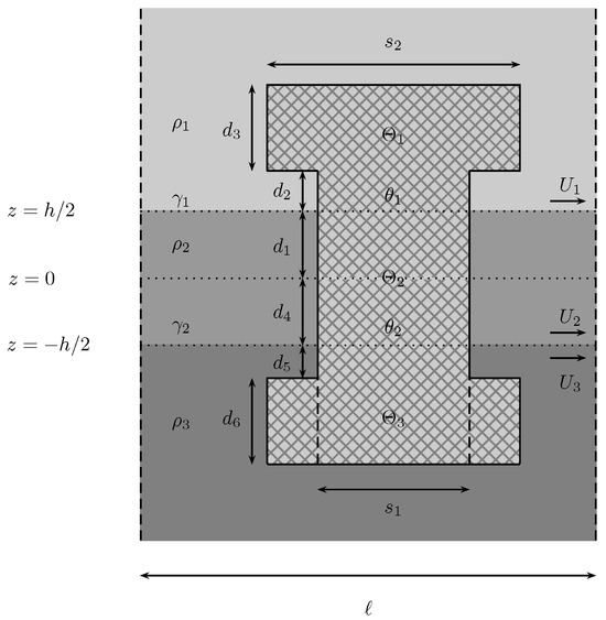
Figure 14.
A vertically symmetric fixed obstacle. Its cross-section for the cylindrical neck has a diameter and the top and bottom circular cross-sections have a diameter .
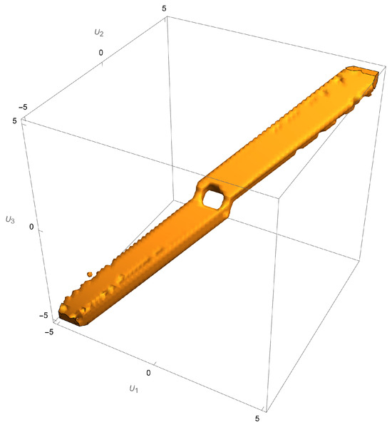
Figure 15.
The intersection of the stability and the sufficient condition regions in velocity space. Not all values of the velocities satisfy the sufficient condition inside the stability region. The symmetry of the layout does not result in the independence of the condition from the velocities.
In the case of two semi-infinite layers (see [29]) there was an independence from the values of the layer velocities if the layout was symmetric. Such is not the case here even with . Despite the irregularities intrinsic to the numerical procedure, it is still observable the necessary left–right symmetry since the image is symmetric with respect to the origin.
Around the origin, the sufficient condition cannot be satisfied (Figure 15). This region is still within the boundaries of stability, so there is no way to satisfy the condition if the layers are still. This agrees with the static situation (see [25]). In the latter, if the sizes of the heads are not large enough, we are between an incomplete column and complete vertical column. Depending on the sizes of the heads, we may or may not compensate for the missing vertical column, which is the borderline case (). However, one can still show that there are trapped modes generated in the case of the vertical column (see [20]). If the heads are not large enough to compensate for the incomplete column, necessarily , which is the case depicted above. However, from this example we can conclude that adding velocities to the layers may change the situation from not satisfying the sufficient condition to its satisfaction, which guarantees the generation of trapped modes. The addition of layer velocities was therefore decisive.
10. Conclusions
The purpose of the present paper was to investigate the influence of background uniform flow on the sufficient condition for the existence of trapped modes in a three-layer, irrotational and inviscid fluid within the framework of the linear water waves theory. This was an improvement on previous studies [5,19,21,22,23,24,25], which were made exclusively for layers at rest. Using the mode velocity as a preferential scale, the original problem could be linearized. The sufficient condition, obtained from a perturbation around the norm of operator T evaluated on , already carried this velocity scale. It was only natural to set this scale to linearise the original problem. The sufficient condition is in fact the sum of two conditions: the proper sufficient condition (76) and the dynamical stability condition (8). They are functions of , , which makes them invariant under global velocity additions. This implies that the results in the first octant of the velocity space are enough to solve for the entire domain.
In the configuration of two semi-infinite layers [29], symmetry played a role regarding the influence of and . The sufficient condition was independent of and when symmetry of the obstacle about the middle interface was present. Here, despite the symmetry of the obstacle with respect to , with interfaces at , the sufficient condition (76) is dependent on , (see Figure 15). In addition, left–right symmetry in [29] allowed to be independent of the background velocity flow, which is no longer the case. Comparison principles for arrays of obstacles submerged in uniformly moving layers can be used whatever the number of layers, the size and format of the obstacles themselves, as is confirmed by the validity of Cavalieri’s principle and other in this configuration.
For a configuration with more than three layers or three layers with a free surface, this analysis is no longer possible due to the limitations imposed by the Abel–Ruffini theorem [37] on the dynamical stability condition. If we add another interface or a free surface to the present configuration, the dynamical stability condition becomes a ninth-degree polynomial equation. Excluding the null solutions, the resulting polynomial is of the sixth degree, making it impossible to derive a general condition for real solutions of multiplicity of one. For configurations of three or more interfaces (including a free surface), only a direct numerical approach is able to provide with results.
Author Contributions
The two authors contributed equally to all parts of this work. All authors have read and agreed to the published version of the manuscript.
Funding
B. M. M. Pereira received no funding for this work. G. A. S. Dias received no funding for this work.
Data Availability Statement
No new data were created or analyzed in this study.
Acknowledgments
The authors thank all the reviewers for their insightful comments, which improved the completeness and relevance of our work.
Conflicts of Interest
The authors confirm their independence and that they have no conflicts of interest regarding this publication.
Abbreviations/Nomenclature
| Wavenumber in the y-direction, . | |
| Discriminant of the dispersion relation. | |
| Doppler factor, , . | |
| Top interface elevation (layers 1 and 2), at . | |
| Bottom interface elevation (layers 2 and 3), at . | |
| Unpierced top interface. | |
| Unpierced bottom interface. | |
| Top interface surface. | |
| Bottom interface surface. | |
| Pierced top interface. | |
| Pierced bottom interface. | |
| Spectral parameter, . | |
| Threshold spectral parameter, . | |
| Inverse spectral parameter, . | |
| Threshold inverse spectral parameter, . | |
| Fluid density in layer j, . | |
| Density ratio, . | |
| Density ratio, . | |
| Obstacle surface in layer j, . | |
| Continuous spectrum of operator T, . | |
| Discrete spectrum of operator T. | |
| Essential spectrum of operator T, . | |
| Operator norm of T. | |
| Velocity potential in layer j, . | |
| Threshold potential, . | |
| Time-harmonic potential in layer j, . | |
| Background flow potential, for , . | |
| Trial function, . | |
| Primed potential, . | |
| z-dependent threshold potential component, . | |
| Test function in layer j, . | |
| Primed test function, . | |
| Fluid region, . | |
| Subregion of within distance from obstacle. | |
| Radian frequency, . | |
| Smallest in modulo non-trivial dispersion relation frequency. | |
| Dispersion relation roots, . | |
| A | Interface term in variational formulation. |
| Threshold solution coefficients. | |
| c | Mode speed, . |
| Threshold mode speed, . | |
| Background flow function, at , . | |
| g | Gravitational acceleration. |
| h | Middle layer thickness. |
| k | Total wavenumber in x- and y-directions. |
| l | Periodicity cell length in y-direction. |
| n | Outward normal vector from the fluid into the obstacles. |
| Surface integral on pierced interface i, . | |
| Discriminant components. | |
| r | Distance to nearest obstacle, . |
| Distance from obstacle boundaries. | |
| T | Trace-interface operator, . |
| y-direction velocity in layer j, . | |
| Uniform velocity shift for all layers. | |
| Volume integral in layer j, . | |
| Function space for quasi-periodic potentials. | |
| Subspace of with quasi-periodicity, . | |
| Fluid domains in layer j, . | |
| Periodicity cell per layer, . | |
| Obstacle in layer j, . |
References
- McIver, P.; McIver, M. Trapped modes in the water-wave problem for a freely floating structure. J. Fluid Mech. 2006, 558, 53–67. [Google Scholar] [CrossRef]
- McIver, P.; McIver, M. Motion trapping structures in the three-dimensional water-wave problem. J. Eng. Math. 2007, 58, 67–75. [Google Scholar] [CrossRef]
- McIver, P.; Newman, J.N. Trapping structures in the three-dimensional water-wave problem. J. Fluid Mech. 2003, 484, 283–301. [Google Scholar] [CrossRef]
- Fitzgerald, C.J.; McIver, P. Passive trapped modes in the water-wave problem for a floating structure. J. Fluid Mech. 2010, 657, 456–477. [Google Scholar] [CrossRef][Green Version]
- Cal, F.S.; Dias, G.A.S.; Pereira, B.M.M.; Videman, J.H. Edge waves propagating in a two-layer fluid along a periodic coastline. J. Eng. Math. 2014, 85, 1–17. [Google Scholar] [CrossRef]
- Stokes, G.G. Report on Recent Researches in Hydrodynamics; Report of the British Association for the Advancement of Science; British Association for the Advancement of Science: London, UK, 1846; pp. 1–20. [Google Scholar]
- Ursell, F. Trapping modes in the theory of surface waves. Math. Proc. Camb. Philos. Soc. 1951, 47, 347–358. [Google Scholar] [CrossRef]
- Ursell, F.; Taylor, G.I. Edge waves on a sloping beach. Proc. R. Soc. Lond. Ser. A Math. Phys. Sci. 1952, 214, 79–97. [Google Scholar] [CrossRef]
- John, F. On the motion of floating bodies II. Simple harmonic motions. Commun. Pure Appl. Math. 1950, 3, 45–101. [Google Scholar] [CrossRef]
- Simon, M.J.; Ursell, F. Uniqueness in linearized two-dimensional water-wave problems. J. Fluid Mech. 1984, 148, 137–154. [Google Scholar] [CrossRef]
- Evans, D.V.; Levitin, M.; Vassiliev, D. Existence theorems for trapped modes. J. Fluid Mech. 1994, 261, 21–31. [Google Scholar] [CrossRef]
- McIver, M. An example of non-uniqueness in the two-dimensional linear water wave problem. J. Fluid Mech. 1996, 315, 257–266. [Google Scholar] [CrossRef]
- Kuznetsov, N.; Maz’ya, V.; Vainberg, B. Linear Water Waves: A Mathematical Approach; Cambridge University Press: Cambridge, UK, 2002. [Google Scholar]
- Linton, C.M.; McIver, P. Embedded trapped modes in water waves and acoustics. Wave Motion 2007, 45, 16–29. [Google Scholar] [CrossRef]
- Kuznetsov, N. Trapped modes of internal waves in a channel spanned by a submerged cylinder. J. Fluid Mech. 1993, 254, 113–126. [Google Scholar] [CrossRef][Green Version]
- Linton, C.M.; Cadby, J.R. Trapped modes in a two-layer fluid. J. Fluid Mech. 2003, 481, 215–234. [Google Scholar] [CrossRef]
- Kuznetsov, N.; McIver, M.; McIver, P. Wave interaction with two-dimensional bodies floating in a two-layer fluid: Uniqueness and trapped modes. J. Fluid Mech. 2003, 490, 321–331. [Google Scholar] [CrossRef]
- Cal, F.S.; Dias, G.A.S.; Nazarov, S.A.; Videman, J.H. Linearised theory for surface and interfacial waves interacting with freely floating bodies in a two-layer fluid. Z. Angew. Math. Phys. 2015, 66, 417–432. [Google Scholar] [CrossRef]
- Kamotskii, I.; Nazarov, S. Exponentially decreasing solutions of the problem of diffraction by a rigid periodic boundary. Math. Notes 2003, 73, 129–131. [Google Scholar] [CrossRef]
- Nazarov, S.A.; Videman, J.H. A sufficient condition for the existence of trapped modes for oblique waves in a two-layer fluid. Proc. R. Soc. A Math. Phys. Eng. Sci. 2009, 465, 3799–3816. [Google Scholar] [CrossRef]
- Nazarov, S.A. A simple method for finding trapped modes in problems of the linear theory of surface waves. Dokl. Math. 2009, 80, 914–917. [Google Scholar] [CrossRef]
- Nazarov, S.A. Sufficient conditions for the existence of trapped modes in problems of the linear theory of surface waves. J. Math. Sci. 2010, 167, 713–725. [Google Scholar] [CrossRef]
- Nazarov, S.A.; Videman, J.H. Existence of edge waves along three-dimensional periodic structures. J. Fluid Mech. 2010, 659, 225–246. [Google Scholar] [CrossRef]
- Cal, F.S.; Dias, G.S.A.; Videman, J.H. Existence of trapped modes along periodic structures in a two-layer fluid. Q. J. Mech. Appl. Math. 2012, 65, 273–292. [Google Scholar] [CrossRef]
- Cal, F.S.; Dias, G.A.S.; Pereira, B.M.M.; Videman, J.H. Trapped modes in a multi-layer fluid. Q. J. Mech. Appl. Math. 2021, 74, 34–54. [Google Scholar] [CrossRef]
- Wilcox, C.H. Scattering Theory for Diffraction Gratings; Springer: Berlin/Heidelberg, Germany, 1984. [Google Scholar]
- Nazarov, S. Trapped surface waves in a periodic layer of a heavy liquid. J. Appl. Math. Mech. 2011, 75, 235–244. [Google Scholar] [CrossRef]
- Craig, W.; Guyenne, P.; Sulem, C. The surface signature of internal waves. J. Fluid Mech. 2012, 710, 277–303. [Google Scholar] [CrossRef]
- Dias, G.A.S. Trapped modes along periodic structures submerged in a two-layer fluid with background steady flow. Math. Methods Appl. Sci. 2023, 46, 18274–18299. [Google Scholar] [CrossRef]
- Vallis, G.K. Atmospheric and Oceanic Fluid Dynamics: Fundamentals and Large-Scale Circulation, 2nd ed.; Cambridge University Press: Cambridge, UK, 2017. [Google Scholar]
- Lamb, H. Hydrodynamics, 6th ed.; Cambridge University Press: Cambridge, UK, 1932. [Google Scholar]
- Kundu, P.; Cohen, I. Fluid Mechanics; Elsevier Science: Amsterdam, The Netherlands, 2010. [Google Scholar]
- Paterson, A.R. A First Course in Fluid Dynamics; Cambridge University Press: Cambridge, UK, 1983. [Google Scholar] [CrossRef]
- Reed, M.; Simon, B. IV: Analysis of Operators; Methods of Modern Mathematical Physics; Elsevier Science: Amsterdam, The Netherlands, 1978. [Google Scholar]
- Drazin, P.G.; Reid, W.H. Hydrodynamic Stability, 2nd ed.; Cambridge Mathematical Library; Cambridge University Press: Cambridge, UK, 2004. [Google Scholar]
- Drazin, P. DYNAMICAL METEOROLOGY|Kelvin–Helmholtz Instability. In Encyclopedia of Atmospheric Sciences, 2nd ed.; North, G.R., Pyle, J., Zhang, F., Eds.; Academic Press: Oxford, UK, 2015; pp. 343–346. [Google Scholar] [CrossRef]
- Irving, R.S. Integers, Polynomials, and Rings: A Course in Algebra; Springer: New York, NY, USA, 2004. [Google Scholar] [CrossRef]
- Sommerfeld, A. Die Greensche Funktion der Schwingungsgleichung. Jahresber. Dtsch. Math.-Ver. 1912, 21, 309–353. [Google Scholar]
- Evans, L. Partial Differential Equations; Graduate Studies in Mathematics; American Mathematical Society: Providence, RI, USA, 2010. [Google Scholar]
- Evans, L.C.; Gariepy, R.F. Measure Theory and Fine Properties of Functions; CRC Press: New York, NY, USA; London, UK, 1992. [Google Scholar]
- Birman, M.S.; Solomjak, M.Z. Spectral Theory of Self-Adjoint Operators in Hilbert Space; D. Reidel Publishing Company: Boston, MA, USA, 1987. [Google Scholar]
- Dean, R.; Dalrymple, R. Water Wave Mechanics for Engineers and Scientists; World Scientific: Singapore, 1991. [Google Scholar]
- Linton, C.M.; Mciver, M. The existence of Rayleigh–Bloch surface waves. J. Fluid Mech. 2002, 470, 85–90. [Google Scholar] [CrossRef]
Disclaimer/Publisher’s Note: The statements, opinions and data contained in all publications are solely those of the individual author(s) and contributor(s) and not of MDPI and/or the editor(s). MDPI and/or the editor(s) disclaim responsibility for any injury to people or property resulting from any ideas, methods, instructions or products referred to in the content. |
© 2025 by the authors. Licensee MDPI, Basel, Switzerland. This article is an open access article distributed under the terms and conditions of the Creative Commons Attribution (CC BY) license (https://creativecommons.org/licenses/by/4.0/).