Abstract
Nowadays, the use of biomechanical devices in medical processes and industrial applications allows us to perform tasks in a simpler and faster way. In the medical field, these devices are becoming more and more common, especially in therapeutic applications. In the design and development of orthopedic devices, it is essential to consider the limbs’ kinematic, kinetic, and anthropometric conditions, as well as the implementation of control strategies (robust, PID, fuzzy, and impedance, among others). This work presents a virtual prototype of a knee orthosis and the implementation of a control system to follow a desired trajectory. Results are presented with the virtual prototype through a co-simulation between MSC Adams and MATLAB Simulink with fuzzy control, virtually replicating the gait cycle.
1. Introduction
Physical health professionals are increasingly resorting to biomechatronic devices to help solve therapeutic problems since these devices facilitate the development of their activities. Tools such as orthoses and exoskeletons improve rehabilitation by providing mechanized assistance in people’s movements. In addition, they reduce the weight of their structural elements, which reduces the energy expenditure in the joints of the extremities through the integration of actuators and control systems [1].
The purpose of biomechatronic device design is to provide stability to improve movements in the limbs of the human body, as well as to offer rehabilitation. Integrating control strategies into devices is a fundamental part of improving the performance and ensuring the security of these systems. Several studies have shown that the use of simulation tools and the implementation or adaptation of control systems contribute to making these devices more efficient and of better quality. Therefore, to achieve a functional design, it is also necessary to consider various aspects, such as design parameters, materials, types of actuators and sensors, and control systems [2,3].
Several designs of biomechatronic devices have been reported in the literature, aimed at providing stability in human gait, providing power and strength in the extremities through the implementation of control systems such as PD, PID, robust control, fuzzy control, and impedance control.
In [4], the implementation of a joint-level impedance controller for series elastic actuators applied in biped robots and robotic assistance devices is reported. Devices have been designed with elastic series actuators driven by Bowden cables, which require electric motors and pulley systems. These devices are similar to the so-called LOPES, which feature impedance control and myoelectric signal acquisition [5,6,7].
In [8,9], they present a robust control for a LOPES exoskeleton based on pneumatic muscle actuators. In [10], a path tracking control strategy using a PD control with adaptive compensation is presented for a lower limb exoskeleton. In [11,12,13,14], the dynamic modeling and PD control of a lower limb exoskeleton is analyzed. The authors of [15] examine PID control for an exoskeleton with Bowden cables. In [16,17,18,19,20], a robust control is proposed and compared with a PID controller.
In the works [21,22], the authors propose an orthosis for a double tendon sheath transmission system, for which they designed a PID control that validates the device. Likewise, they develop a fuzzy controller for walking assistance. In [23], an intelligent control for the walking of a biped robot, based on fuzzy logic, is presented.
Fuzzy control is a control method based on fuzzy logic used to handle systems that are difficult to model accurately. When combined with PID control, a fuzzy self-tuning PID controller is obtained, where PID control laws based on linguistic description are applied in decision-making [24,25].
In [26], the position and torque parameters of hip, knee, and ankle joints during the walking cycle are analyzed with a planned structure of series elastic actuators. In 2017, ref. [27] proposed an active impedance control strategy for knee joint orthosis. Ref. [28] describes the design of fuzzy logic-based control for a knee joint orthosis using inertial sensors located on the sole to develop the walking cycle. In [29,30,31,32], the modeling of fuzzy control for a pendulum system is discussed. In [33,34,35,36,37,38,39], adaptive fuzzy control is studied compared to a classical PID control, where fuzzy rules for the parameters Kp, Ki, and Kd, applied to actuator control, are proposed. In [40], a fuzzy control integrated with a classical PID control for an upper limb is presented; in [41,42], a fuzzy self-tuning PID control applied to a hydrogen-powered artificial pneumatic muscle actuator is presented.
Myoelectric signals have been acquired to characterize parameters in biomechatronic devices. In [43], the torque and position parameters of the knee joint are characterized and normalized through myoelectric signals using a prototype based on LOPES actuators. In [44], an impedance control with force and torque sensors using myoelectric signals in a knee orthosis is presented. In 2020, ref. [45] presented a robust control using a second-order sliding mode strategy applied as a torque algorithm with adaptive gain for an exoskeleton. Additionally, studies have been developed with control systems based on IMU sensors and microcontroller programming. In [46], the implementation of an integrated control system with three IMUs, a microcontroller module, and a Bluetooth module in a knee orthosis is analyzed.
Similarly, the literature shows that computer-aided engineering (CAE) software is a practical tool for simulation and should be considered in kinematic and kinetic analysis during the design of devices in various applications. Using CAE in virtual prototypes allows for interactive and dynamic analysis of robotic systems through simulation, which facilitates control and visualization of desired displacements and/or trajectories of the devices in a virtual environment.
In [31,36], a MATLAB/Simulink (R2023b SV) simulation of fuzzy logic control is applied to an inverted pendulum system to achieve angular control of the device. Additionally, results related to the characterization of motion, velocity, acceleration, and torque have been presented, as well as those obtained from biomechatronic prototype designs. In [47], a co-simulation in ADAMS 2012/MATLAB of a robotic prototype based on a double pendulum system is shown, while [39,48] evaluate a co-simulation of a lower limb exoskeleton and its dynamic model using the Lagrangian formulation and fuzzy control. In [49], an ADAMS/MATLAB co-simulation with Simscape Multibody of a closed-loop mechanism is analyzed.
On the other hand, [33,42] present a simulation of fuzzy and PID control in MATLAB/Simulink, in which fuzzy rules are proposed for the parameters KP, KI, and KD in the control of electric actuators. Ref. [38] shows a fuzzy PID control simulation applied to a three-degree-of-freedom parallel mechanism.
The reviewed literature concludes that computer-aided engineering systems are tools that facilitate the design and manufacturing processes in orthopedic systems, such as prostheses, orthoses, and exoskeletons. Their use provides a clear and early understanding of the necessary analysis for each prototype, including simulations and kinematic and kinetic analysis calculations, which helps reduce construction time. Additionally, they assist in designing control algorithms tailored to the applications and needs of patients, preventing manufactured designs from presenting errors or singularities when replicating movements or when physically implemented in patients.
Section 2 presents the design proposal for a robotic knee orthosis in this work. In Section 3, the dynamic model is developed, considering the device as a simple pendulum based on the orthosis design. Section 4 proposes the adaptation of a fuzzy PID control system. Section 5 presents the results obtained from a simulation in ADAMS/Simulink of MATLAB, focused on tracking a walking cycle trajectory. The comparison between the fuzzy control and the PID control implemented in the orthosis system is also shown. Finally, Section 6 presents the conclusions of this work.
2. Virtual Prototype of the Orthosis
The reviewed literature on the design and development of orthopedic devices, such as robotic knee orthoses, concludes that the use of elastic actuators or Bowden cables in mechanical systems for joints efficiently generates movements, saves energy, and reduces metabolic costs. Furthermore, reducing the number of actuators in a robotic system allows for the design of compact and lightweight orthoses. For these reasons, the following orthosis design was proposed.
A virtual prototype of a lower limb orthosis was designed to provide flexion and extension movement of the knee joint. This mechanism comprises adjustable rigid structures, considering the characteristics required by the limb. The design is simple, and its components were designed using design and assembly methodologies, which facilitate manufacturing and assembly.
The CAD model of the robotic orthosis consists of an adjustable structure for the thigh and another for the calf of the lower limb (see Figure 1a), as well as adjustable vertical structures along the thigh and calf (see Figure 1b). These structures were designed to adapt to the individual physical conditions (thigh and calf dimensions),allowing the orthosis to be adjusted in length and width. Additionally, it includes lifting ears for attachment to the limb using straps.
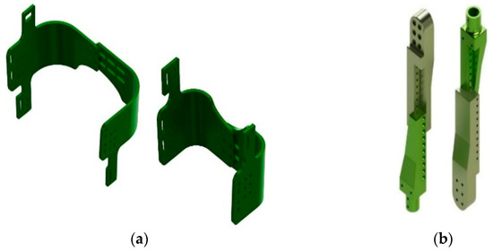
Figure 1.
Adjustable orthosis bases: (a) adjustable thigh and calf base, (b) adjustable structure parallel to the thickness.
The proposed orthosis’s design incorporates a spherical joint to allow knee movement, providing a more natural motion and avoiding restrictions in the planes where the movement occurs (see Figure 2).
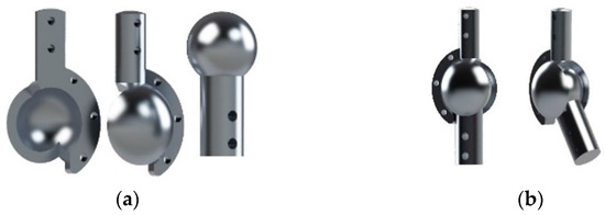
Figure 2.
Sphere type joint: (a) exploded view of the ball joint, (b) spherical joint in two positions.
This biomechatronic device consists of a rotary actuator located at the top of the orthosis, which generates the flexion and extension movement. A two-pulley system is proposed: one pulley is fixed to the rotary actuator, and the other is located at the lower part of the calf. The pulley system is connected via a Bowden steel cable, which transmits the movement from the thigh to the calf. These cables are secured to the perimeter of the adjustable vertical structures through attachment points with clamps (see Figure 3).
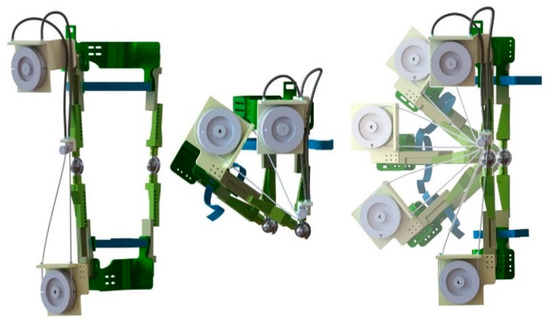
Figure 3.
Virtual prototype of the orthosis.
3. Dynamic Model
In the simulation of biomechatronic devices, the kinematics and kinetics of the systems to be designed must be considered in order to properly and efficiently control the movements involved in rehabilitation processes or trajectory tracking. Through mathematical models, whether simplified or complex, the goal is to characterize the movements and control and/or anticipate possible disturbances.
As shown in Figure 4, the orthosis dynamics can be modeled as a simple pendulum, considering only the flexion/extension motion. The degree of freedom is defined by the knee angle or the angle formed between the two links of the orthosis. The Euler–Lagrange formula is used to determine the equations governing this dynamic. The following values were considered for the simulation: a mass of 2.39 kg, an orthosis length of 0.654 m, and a torque of 8.46 Nm.
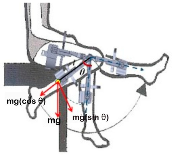
Figure 4.
Free body diagram of the orthosis.
The EulerLagrange equation is expressed as follows:
The Lagrangian is given by the kinetic energy minus the potential energy of the system:
Therefore,
Applying (1), finally the dynamic equation of the system can be expressed as follows:
The linearized model can be obtained considering that the variations around the equilibrium point are minor when the pendulum is vertical.
Desired Trajectory
An essential aspect of biomechatronic device development is the implementation of a control system designed to track trajectories and provide smooth movements. This work uses a virtual prototype of the orthosis to evaluate and analyze device performance. Furthermore, a Bézier polynomial was used to define a trajectory, enabling smooth and continuous movement during acceleration and deceleration phases (see Figure 5).
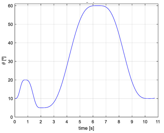
Figure 5.
Walking cycle with polynomial 4, 5, 6, 7.
The prototype’s trajectory tracking is described using the Bézier polynomial (7), with the following parameters: γ1 = 252, γ2 = 1050, γ3 = 1800, γ4 = 1575, γ5 = 700, γ6 = 126 [50,51]. Applying this polynomial function allows for the definition of continuous and stable trajectories, with smooth and precise curves and movements to achieve efficient displacement.
Path tracking control implemented in a virtual prototype is a way to validate the functionality of mechatronic devices and then implement them in a physical prototype that provides the desired movements. In this case, it is proposed that the virtual prototype perform the gait cycle. Therefore, the Bézier polynomial was implemented in Simulink (see Figure 6a) to complete 100% of the cycle in approximately 10 s, a value proposed by the authors (see Figure 6b).
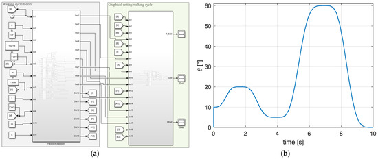
Figure 6.
Desired Bézier polynomial trajectory: (a) scheme of the walk/Bézier cycle, (b) desired trajectory.
4. Control System
Automatic control is an integral part of industrial and medical processes, as it allows for better performance of dynamic systems, facilitates repetitive operations, and improves productivity. Control systems must be considered in the design and handling of biomechatronic systems and/or prototypes, as control involves the interaction of different elements through variables with established ranges. This interaction is essential to maintaining motion or precise positioning during the development of their processes.
The literature describes a wide variety of control techniques applied to biomechatronic systems, such as PD, PID, impedance control, robust control, and fuzzy logic-based control. The common goal is to develop stable and precise movements that do not interfere with the natural movements of the limbs.
Based on the review, the implementation and adaptation of a fuzzy PID control system in the knee orthosis device is presented. Fuzzy control is a method based on fuzzy logic used in systems that are difficult to model, meaning there is no well-defined mathematical model. This type of fuzzy control offers a wide operating range and excellent adaptability, making it suitable for controlling nonlinear systems. Additionally, it allows for incorporating knowledge based on human experience to design a fuzzy controller that meets the required control tasks.
4.1. PID Fuzzy Control
This work is based on the research described by [33,41,42], where a fuzzy self-tuning scheme for PID control is proposed to regulate the action of actuators. The gain programming is implemented according to fuzzy self-tuning and reasoning rules based on the system modeling to determine the PID controller gain parameters. These gains are obtained using the Ziegler–Nichols tuning method based on the system’s transient response to a step input under operating conditions (trial and error). This method allows for establishing initial estimates of the PID gains, which are used in the membership functions of the fuzzy control rules [52].
The input error is set within a range of [−6, 6], the output variable kP has a range of [−0.5, 0.5]; kI has a range of [−0.5, 3]; and the variable kD has a range of [−1, 2].
The design parameters must be carefully selected to build a fuzzy controller, which involves choosing the appropriate membership functions and formulating a fuzzy rule base [24,25]. When the control response is closer to the analysis point, the membership function corresponding to the linguistic variable should have a narrow range. The number of linguistic values and the contraction factor are the only parameters needed to establish the membership functions of the linguistic variable [32].
4.2. PID Fuzzy Control Rules
The fuzzy rules, the max–min inference mechanism, and the defuzzification process are based on the Mamdani model to tune the PID gains of KP, KI, and KD. As described in [33,41,42], the PID control is implemented through proportional, integral, and derivative operations, according to Equation (10). For the implementation of fuzzy control in knee orthosis, the membership functions mentioned in [33,41], and [42] were used, which were introduced through the MATLAB/Simulink software using the “fuzzyLogicDesigner” command in the command window. The correct construction of the membership function is key to using fuzzy control. Figure 7 shows the rules used in the fuzzy control.
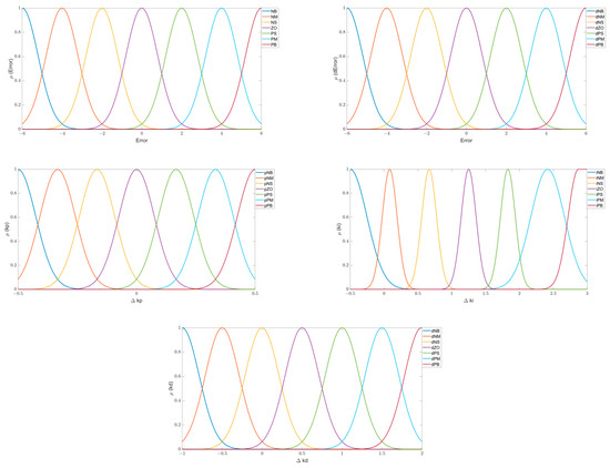
Figure 7.
Membership functions [46].
Likewise, from [33,41,42], we considered implementing the max-min inference mechanism; for ΔKP, the rule is ; for ΔKI, the rule is ; for ΔKD, the rule is ; the fuzzy rules of the self-tuning modules are shown in Table 1, Table 2 and Table 3.

Table 1.
Fuzzy rules for ΔKP.
Table 2.
Fuzzy rules for ΔKI.
Table 3.
Fuzzy rules for ΔKD.
4.3. Fuzzy Control Simulation Model
For the creation of the simulation model of the fuzzy PID controller system in the MATLAB/Simulink software, the parameters established by the particle swarm algorithm were considered for optimization. This stochastic optimization technique, based on populations, allows for obtaining defuzzification factors, as mentioned in [33,42]. The algorithm starts with a group of N particles and seeks the optimal solution through an iterative process. In each iteration, the particles update their optimal position extremes (OPEs) and the global optimal position extremes (GPEs), tracking both their OPEs and the GPEs to update their velocity and position. Equations (11) and (12) describe the process of optimization for position and velocity.
The algorithm was evaluated with the following parameters: a population of 50 particles, each with a dimension equal to 5. The initial values for the defuzzification factors ke, kec, kP1, kI1, and kD1 were considered as the set [1, 1, 1, 1, 1, 1, 1]. The maximum number of iterations was set to 100; the coefficients c1 and c2 were fixed at 2, and the value of ω was set to 0.95. The velocity range of the particles was set to [−500, 500], and the position range was set to [−4, 4]. The following results were obtained with these parameters: ke = 0.8, kec = 0.2, kP1 = 0.5, kI1 = 8, and kD1 = −0.1.
A simulation model of the system was established, which mainly consists of a fuzzy PID controller, a disturbance signal, a controlled system, and a control setpoint, combining the transfer function of the closed-loop system and the PID parameters, as described in [42] (see Figure 8).
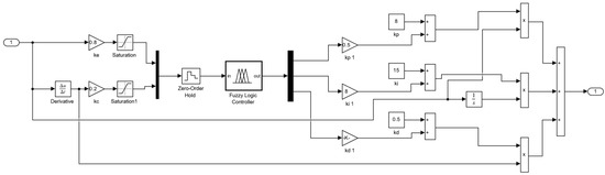
Figure 8.
Simulink diagram of PID fuzzy control.
Taking into account the conditions, characteristics, and diagram for the fuzzy PID control proposed in [42], an adaptation of this control algorithm was made to implement it in the knee orthosis proposed in this work, considering the trajectory resulting from the application of the Bézier polynomial mentioned in Section Desired Trajectory. Figure 9 shows the block diagram of the desired trajectory, the fuzzy control, and the control plant of the system of the virtual prototype in Adams to perform the Adams/MATLAB–Simulink co-simulation, considering the dynamic model from Section 3.

Figure 9.
Simulink diagram of the Adams control/plant.
5. Results
The Adams/MATLAB co-simulation of the virtual biomechatronic device for knee orthosis was carried out, considering the parameters established in [33,42], as mentioned in Section 4.3 of this manuscript. The results obtained from this co-simulation show that the device performs trajectory tracking of the gait cycle, based on the values established in Section Desired Trajectory, during the flexion and extension movements.
Several simulations were conducted for the co-simulation, considering different times to complete 100% of the gait cycle. This means testing various speeds at which the orthosis device can perform the cycle; that is, the longer the time, the lower the speed at which the flexionextension movement of the gait cycle is executed, and the shorter the time, the higher the speed. The orthosis device is capable of tracking the proposed trajectory at different time intervals. In this work, the results obtained from the co-simulation are presented for durations of 10 and 42 s for the whole gait cycle, with these times proposed by the authors.
During the development of the gait cycle using the fuzzy PID control with a duration of 10 s, the device shows a trajectory similar to the desired one. As it approaches the maximum and minimum points of the path—i.e., during the change in movement direction (actuator rotation reversal)—a phase shift of less than 1° is observed at 20° of flexion, representing 17% of the cycle. At 45% of the cycle, the device follows the same trajectory as the one defined by the Bézier polynomial. During the extension movement, at 65% of the cycle, an approximate deviation of 2° is observed, and by the end of the movement, the deviation exceeds 2°. Additionally, during the change in movement direction, displacement singularities of the device are observed. This corresponds to the system’s transient response to the polarity change in the actuator, which occurs over approximately 0.8 s and is rapidly reduced through the application of the fuzzy PID control (see Figure 10a).
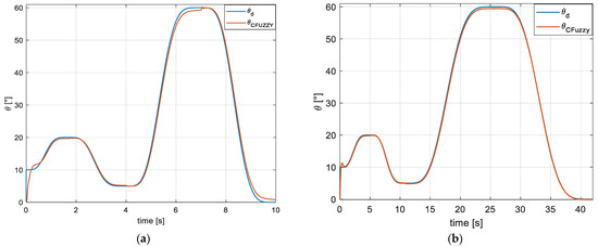
Figure 10.
PID fuzzy simulation/control: (a) simulation at t = 10 s, (b) simulation at t = 42 s.
Figure 10b shows the device’s behavior performing the desired trajectory over 42 s. It can be observed that the device follows the proposed trajectory closely, with a difference of approximately one degree during the transition from flexion to extension between 60% and 70% of the gait cycle, without exhibiting the system’s transient response during the change in movement direction.
Considering the results obtained with the fuzzy PID control and comparing them to those of conventional control methods, a co-simulation was carried out using the classic PID controller available in MATLAB/Simulink. The simulation used the default values assigned by the software: KP = 1, KI = 1, and KD = 0. It considered time durations of 10 and 42 s to complete the gait cycle.
In the 10 s co-simulation, the gait cycle trajectory tracking was achieved, but without reaching the values established in Section Desired Trajectory. A deviation of 5° was observed at 20° of flexion, representing 17% of the cycle. Between 35% and 45% of the cycle, a difference of 2.5° was observed during the extension movement; between 60% and 70%, an approximate deviation of 15° was noted, and at the end of the movement, the deviation exceeded 10°. Additionally, instability singularities were observed at each change in movement—that is, when reaching the maximum flexion point and beginning extension, and vice versa—as shown in Figure 11a.
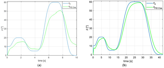
Figure 11.
Simulation/classic PID control in Simulink: (a) simulation at t = 10 s, (b) simulation at t = 42 s.
Figure 11b shows the simulation with a duration of 42 s. It can be observed that the deviations presented in the 10 s simulation are reduced to 3° at 17% of the cycle; between 35% and 45%, the deviation reduces to 2°; between 60% and 70%, the approximate deviation is 4°, and at the end of the movement, the deviation is less than 5°.
Another simulation was carried out in which the classic PID control presented in MATLAB/Simulink was given values of KP = 8.5, KI = 23, and KD = 0.5, obtained from [33,42] for the fuzzy PID control. In this co-simulation, trajectory tracking was achieved during the 10 s duration, with minor deviations, reflecting a trajectory similar to that presented in the fuzzy PID control co-simulation. However, the observed deviation is approximately 1° during the complete cycle development compared to the fuzzy control. Additionally, the response shows a larger transient step at the beginning and during the change in movement, as shown in Figure 12a.
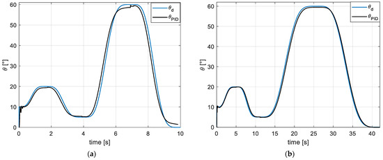
Figure 12.
Simulation/classical PID control for KP = 8.5, KI = 23, and KD = 0.5: (a) simulation at t = 10 s, (b) simulation at t = 42 s.
Figure 12b shows that the deviation is reduced with the PID control and a duration of 42 s. Upon reaching each movement’s maximum and minimum points, a deviation of approximately 1° is still observed. The transient at the beginning of the trajectory cycle is broader compared to the fuzzy PID control. Similarly, transients are still observed during the direction change for each movement of the gait cycle.
Figure 13 shows a comparison of the three controls applied in the co-simulation of the virtual prototype of the orthosis. It can be observed that the classic PID control presents a more significant deviation in tracking the desired trajectory. The PID control, with KP, KI, and KD values equal to those applied in the fuzzy PID control, shows a time deviation when performing both movements, with a greater emphasis on the 60° flexion of the cycle. This behavior is similar to that observed in the fuzzy control, with a deviation of 1° less in the required angles for extension during the gait cycle.
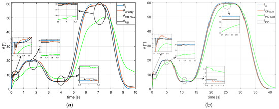
Figure 13.
Comparison of PID simulation/fuzzy control vs. PID control: (a) simulation at t = 10 s, (b) simulation at t = 42 s.
In the trajectory presented with the fuzzy PID control, a behavior similar to the proposed desired trajectory is observed, maintaining a range equal to that required for the flexion and extension movements of the cycle. In the presented controls, singularities are observed during the change in movement between flexion and extension; that is, the response exhibits a state of system instability during the direction change. The startup and direction reversal of the motor causes these singularities. In Figure 13a, it can be seen that this transient step in the trajectory tracking response reaches its stable state in a time of 0.5 s, which is shorter compared to the one shown in the 10 s simulation. Additionally, the transient is less pronounced in the results presented with the fuzzy PID control.
Table 4 compares the simulation results of the three control methods at the beginning of the gait cycle trajectory. This phase of the cycle is where the most significant system instability occurs. The table shows that as the time to complete the cycle increases, the instability decreases, and the stabilization time is reduced.
Table 4.
Comparison of the three control methods.
6. Conclusions
Conventional control systems are precise when adequate mathematical models are available for systems whose dynamic behavior is known or easily deducible for implementation. However, in a biomechatronic device, fuzzy logic is recommended, as this control method is based on deduction, observations, and practical applications.
This work presented the adaptation of three types of control virtually, demonstrating that fuzzy logic is an efficient tool for dynamically developing a control algorithm when an exact mathematical deduction is unavailable. The results show the virtual behavior of the biomechatronic device mentioned in Section 2. With the implementation of a classic PID control with different values for KP, KI, and KD, it was observed that the trajectory followed by the device is like the desired one, although with disturbances during the change in movement and relatively short stabilization times.
The implementation of a fuzzy PID control, which combines fuzzy logic and conventional PID control, is presented. This approach performs better than classic PID control, as the disturbances have smaller amplitudes, and the stabilization time is shorter. The combination of these controls allows the development of a controller capable of maintaining a stable gait by the desired trajectory. Based on this analysis, it is concluded that the use of fuzzy PID control produces better results compared to classic PID control.
In conclusion, the co-simulation analysis provides a precise understanding of the functioning of the proposed design for the robotic knee orthosis, adapted to the needs of each patient. This facilitates the implementation of an interactive control with algorithms that promote its application in individuals’ daily lives or rehabilitation processes. In future work, biomechatronic devices are expected to be autonomous and perform movements similar to those of human nature. The results presented in this work show that the proposed orthosis design and the fuzzy PID control algorithm complement each other to form an autonomous device that can be used in rehabilitation tasks. Furthermore, it demonstrates a viable option for future construction and implementation as an orthopedic device in rehabilitation.
Author Contributions
Conceptualization, A.B.S. and A.B.O.; methodology, A.B.S., A.B.O., C.H.G.V. and H.R.A.R.; software, C.M.V., C.H.G.V. and A.M.M.; validation, H.R.A.R., A.M.M. and R.C.A.; formal analysis, A.B.S., A.B.O. and C.M.V.; investigation, A.B.S. and A.B.O.; resources, A.B.O.; data curation, H.R.A.R. and C.H.G.V.; writing—originaldraft preparation, A.B.S.; writing—review and editing, A.B.S. and A.B.O.; visualization, A.M.M., C.H.G.V. and R.C.A.; supervision, A.B.S. and A.B.O.; project administration, A.B.S., A.B.O. and C.M.V.; funding acquisition, A.B.S., A.B.O. and R.C.A. All authors have read and agreed to the published version of the manuscript.
Funding
This research received no external funding.
Institutional Review Board Statement
Not applicable.
Informed Consent Statement
Not applicable.
Data Availability Statement
The original contributions presented in this study are included in the article. Further inquiries can be directed to the corresponding author(s).
Acknowledgments
The authors thank the Tecnológico Nacional de México and the Centro Nacional de Investigación y Desarrollo Tecnológico for the support provided to carry out this work. Agustín Barrera Sánchez thanks CONACYT for the scholarship granted to carry out his postgraduate studies.
Conflicts of Interest
The authors have declared that they have no conflict of interest in the publication of this manuscript.
References
- Barrera Sánchez, A.; Blanco Ortega, A.; Martínez Rayón, E.; Gómez Becerra, F.A.; Abúndez Pliego, A.; Campos Amezcua, R.; Guzmán Valdivia, C.H. State of the Art Review of Active and Passive Knee Orthoses. Machines 2022, 10, 865. [Google Scholar] [CrossRef]
- Lara-Barrios, C.M.; Blanco-Ortega, A.; Guzmán-Valdivia, C.H.; Bustamante Valles, K.D. Literature review and current trends on transfemoral powered prosthetics. Adv. Robot. 2018, 32, 51–62. [Google Scholar] [CrossRef]
- Villa-Parra, A.; Delisle-Rodriguez, D.; Lima, J.S.; Frizera-Neto, A.; Bastos, T. Knee Impedance Modulation to Control an Active Orthosis Using Insole Sensors. Sensors 2017, 17, 2751. [Google Scholar] [CrossRef] [PubMed]
- Pratt, G.A.; Willisson, P.; Bolton, C.; Hofman, A. Late motor processing in low-impedance robots: Impedance control of series-elastic actuators. In Proceedings of the 2004 American Control Conference, Boston, MA, USA, 30 June–2 July 2004; Volume 4, pp. 3245–3251. [Google Scholar] [CrossRef]
- Veneman, J.F.; Ekkelenkamp, R.; Kruidhof, R.; van der Helm, F.C.T.; van der Kooij, H. A Series Elastic- and Bowden-Cable-Based Actuation System for Use as Torque Actuator in Exoskeleton-Type Robots. Int. J. Rob. Res. 2006, 25, 261–281. [Google Scholar] [CrossRef]
- van der Kooij, H.; Veneman, J.; Ekkelenkamp, R. Design of a compliantly actuated exoskeleton for an impedance controlled gait trainer robot. In Proceedings of the 2006 International Conference of the IEEE Engineering in Medicine and Biology Society, New York, NY, USA, 30 August–3 September 2006; pp. 189–193. [Google Scholar] [CrossRef]
- Veneman, J.F.; Kruidhof, R.; Hekman, E.E.G.; Ekkelenkamp, R.; Van Asseldonk, E.H.F.; van der Kooij, H. Design and Evaluation of the LOPES Exoskeleton Robot for Interactive Gait Rehabilitation. IEEE Trans. Neural Syst. Rehabil. Eng. 2007, 15, 379–386. [Google Scholar] [CrossRef]
- Hussain, S.; Xie, S.Q.; Jamwal, P.K. Robust Nonlinear Control of an Intrinsically Compliant Robotic Gait Training Orthosis. IEEE Trans. Syst. Man. Cybern. Syst. 2013, 43, 655–665. [Google Scholar] [CrossRef]
- Mefoued, S. A second order sliding mode control and a neural network to drive a knee joint actuated orthosis. Neurocomputing 2015, 155, 71–79. [Google Scholar] [CrossRef]
- Lopez, R.; Aguilar-Sierra, H.; Salazar, S.; Torres, J.; Lozano, R. Adaptive control for passive kinesiotherapy ELLTIO. In Proceedings of the 2013 16th International Conference on Advanced Robotics (ICAR), Montevideo, Uruguay, 25–29 November 2013; pp. 1–6. [Google Scholar] [CrossRef]
- López, R.; Aguilar, H.; Salazar, S.; Lozano, R.; Torres, J.A. Modelado y Control de un Exoesqueleto para la Rehabilitación de Extremidad Inferior con dos grados de libertad. Rev. Iberoam. Automática Informática Industrial RIAI 2014, 11, 304–314. [Google Scholar] [CrossRef]
- Santos, W.M.D.; Caurin, G.A.P.; Siqueira, A.A.G. Design and control of an active knee orthosis driven by a rotary Series Elastic Actuator. Control Eng. Pract. 2017, 58, 307–318. [Google Scholar] [CrossRef]
- Bacek, T.; Moltedo, M.; Langlois, K.; Rodriguez-Guerrero, C.; Vanderborght, B.; Lefeber, D. A novel modular compliant knee joint actuator for use in assistive and rehabilitation orthoses. In Proceedings of the 2017 IEEE/RSJ International Conference on Intelligent Robots and Systems (IROS), Vancouver, BC, Canada, 24–28 September 2017; pp. 5812–5817. [Google Scholar] [CrossRef]
- Ahmed, N.; Humaidi, A.; Sabah, A. Clinical Trajectory control for lower Knee rehabilitation using ADRC method. J. Appl. Res. Technol. 2022, 20, 576–583. [Google Scholar] [CrossRef]
- Shi, Y.; Guo, M.; Hui, C.; Li, S.; Ji, X.; Yang, Y.; Luo, X.; Xia, D. Learning-Based Repetitive Control of a Bowden-Cable-Actuated Exoskeleton with Frictional Hysteresis. Micromachines 2022, 13, 1674. [Google Scholar] [CrossRef] [PubMed]
- Mefoued, S. A robust adaptive neural control scheme to drive an actuated orthosis for the assistance of knee movements. Neurocomputing 2014, 140, 27–40. [Google Scholar] [CrossRef]
- Mefoued, S.; Mohammed, S.; Amirat, Y. Knee joint movement assistance through robust control of an actuated orthosis. In Proceedings of the 2011 IEEE/RSJ International Conference on Intelligent Robots and Systems, San Francisco, CA, USA, 25–30 September 2011; pp. 1749–1754. [Google Scholar] [CrossRef]
- Rifai, H.; Hassani, W.; Mohammed, S.; Amirat, Y. Bounded control of an actuated lower limb orthosis. In Proceedings of the IEEE Conference on Decision and Control and European Control Conference, Orlando, FL, USA, 12–15 December 2011; pp. 873–878. [Google Scholar] [CrossRef]
- Alvarez-Ramirez, J.; Kelly, R.; Cervantes, I. Semiglobal stability of saturated linear PID control for robot manipulators. Automatica 2003, 39, 989–995. [Google Scholar] [CrossRef]
- Önen, Ü.; Botsalı, F.M.; Kalyoncu, M.; Şahin, Y.; Tınkır, M. Design and Motion Control of a Lower Limb Robotic Exoskeleton. In Design, Control and Applications of Mechatronic Systems in Engineering; InTech: London, UK, 2017. [Google Scholar] [CrossRef]
- Shan, H.; Jiang, C.; Mao, Y.; Wang, X. Design and control of a wearable active knee orthosis for walking assistance. In Proceedings of the 2016 IEEE 14th International Workshop on Advanced Motion Control (AMC), Auckland, New Zealand, 22–24 April 2016; pp. 51–56. [Google Scholar] [CrossRef]
- Lu, J.; Haninger, K.; Chen, W.; Tomizuka, M. Design and torque-mode control of a cable-driven rotary series elastic actuator for subject-robot interaction. In Proceedings of the 2015 IEEE International Conference on Advanced Intelligent Mechatronics (AIM), Busan, Republic of Korea, 7–11 July 2015; pp. 158–164. [Google Scholar] [CrossRef]
- Rivera, J.A.Q.; Ross, O.H.M.; Cruz, R.S.; Castillo López, O. Design and Implementation of Intelligent Controllers in Soft Processors for the Walking of a Biped Robot. Comput. Sist. 2018, 22, 1431–1442. [Google Scholar] [CrossRef]
- Mamdani, E.H.; Assilian, S. An experiment in linguistic synthesis with a fuzzy logic controller. Int. J. Man. Mach. Stud. 1975, 7, 1–13. [Google Scholar] [CrossRef]
- Mamdani. Application of Fuzzy Logic to Approximate Reasoning Using Linguistic Synthesis. IEEE Trans. Comput. 1977, C-26, 1182–1191. [Google Scholar] [CrossRef]
- Sulzer, J.S.; Gordon, K.E.; Hornby, T.G.; Peshkin, M.A.; Patton, J.L. Adaptation to knee flexion torque during gait. In Proceedings of the 2009 IEEE International Conference on Rehabilitation Robotics, Kyoto, Japan, 23–26 June 2009; pp. 713–718. [Google Scholar] [CrossRef]
- el zahraa Wehbi, F.; Huo, W.; Amirat, Y.; El Rafei, M.; Khalil, M.; Mohammed, S. Active impedance control of a knee-joint orthosis during swing phase. In Proceedings of the 2017 International Conference on Rehabilitation Robotics (ICORR), London, UK, 17–20 July 2017; pp. 435–440. [Google Scholar] [CrossRef]
- Ma, H.; Lai, W.-Y.; Liao, W.-H.; Fong, D.T.-P.; Chan, K.-M. Design and control of a powered knee orthosis for gait assistance. In Proceedings of the 2013 IEEE/ASME International Conference on Advanced Intelligent Mechatronics, Wollongong, NSW, Australia, 9–12 July 2013; pp. 816–821. [Google Scholar] [CrossRef]
- Zhang, L.; Li, M. Fuzzy modeling and control of a class of simple pendulum system based on robust technology. In Proceedings of the 2017 6th Data-Driven Control and Learning Systems (DDCLS), Chongqing, China, 26–27 May 2017; pp. 168–173. [Google Scholar] [CrossRef]
- Kumar, A.; Sharma, S.; Mitra, R. Design of Type-2 Fuzzy Controller based on LQR Mapped Fusion Function. Int. J. Intell. Syst. Appl. 2012, 4, 18–29. [Google Scholar] [CrossRef]
- Liu, Y.; Chen, Z.; Xue, D.; Xu, X. Real-time controlling of inverted pendulum by fuzzy logic. In Proceedings of the 2009 IEEE International Conference on Automation and Logistics, Shenyang, China, 5–7 August 2009; pp. 1180–1183. [Google Scholar] [CrossRef]
- Brock, S. Practical approach to fuzzy control of inverter pendulum [for inverter read inverted]. In Proceedings of the IEEE International Conference on Industrial Technology, Maribor, Slovenia, 10–12 December; 2003; pp. 31–35. [Google Scholar] [CrossRef]
- Ochoa, G.V.; Forero, J.D.; Quinones, L.O. Fuzzy adaptive PID controller applied to an electric heater in MATLAB/Simulink. Contemp. Eng. Sci. 2018, 11, 2849–2856. [Google Scholar] [CrossRef]
- Liu, X.; Liu, M. Research on Artificial Intelligence Controller of DC Motor. Sci. J. Technol. 2023, 5, 6–14. [Google Scholar] [CrossRef]
- Wang, Y.; Jin, Q.; Zhang, R. Improved fuzzy PID controller design using predictive functional control structure. ISA Trans. 2017, 71, 354–363. [Google Scholar] [CrossRef]
- El-Nagar, A.M.; El-Bardini, M. Practical Implementation for the interval type-2 fuzzy PID controller using a low cost microcontroller. Ain Shams Eng. J. 2014, 5, 475–487. [Google Scholar] [CrossRef]
- Attia, A.-H.; Rezeka, S.F.; Saleh, A.M. Fuzzy logic control of air-conditioning system in residential buildings. Alex. Eng. J. 2015, 54, 395–403. [Google Scholar] [CrossRef]
- Zhu, Z.; Liu, Y.; He, Y.; Wu, W.; Wang, H.; Huang, C.; Ye, B. Fuzzy PID Control of the Three-Degree-of-Freedom Parallel Mechanism Based on Genetic Algorithm. Appl. Sci. 2022, 12, 11128. [Google Scholar] [CrossRef]
- Urrea, C.; Kern, J.; Alvarado, J. Design and Evaluation of a New Fuzzy Control Algorithm Applied to a Manipulator Robot. Appl. Sci. 2020, 10, 7482. [Google Scholar] [CrossRef]
- Nasr, A.; Hashemi, A.; McPhee, J. Model-Based Mid-Level Regulation for Assist-As-Needed Hierarchical Control of Wearable Robots: A Computational Study of Human-Robot Adaptation. Robotics 2022, 11, 20. [Google Scholar] [CrossRef]
- Nuchkrua, T.; Leephakpreeda, T. Fuzzy Self-Tuning PID Control of Hydrogen-Driven Pneumatic Artificial Muscle Actuator. J. Bionic Eng. 2013, 10, 329–340. [Google Scholar] [CrossRef]
- Zhao, C.; Liu, Z.; Zhu, L.; Wang, Y. Design and Research of Series Actuator Structure and Control System Based on Lower Limb Exoskeleton Rehabilitation Robot. Actuators 2024, 13, 20. [Google Scholar] [CrossRef]
- Celebi, B.; Yalcin, M.; Patoglu, V. AssistOn-Knee: A self-aligning knee exoskeleton. In Proceedings of the 2013 IEEE/RSJ International Conference on Intelligent Robots and Systems, Tokyo, Japan, 3–7 November 2013; pp. 996–1002. [Google Scholar] [CrossRef]
- Huo, W.; Mohammed, S.; Amirat, Y. Observer-based active impedance control of a knee-joint assistive orthosis. In Proceedings of the 2015 IEEE International Conference on Rehabilitation Robotics (ICORR), Singapore, 11–14 August 2015; pp. 313–318. [Google Scholar] [CrossRef]
- Rakhtala, S.M. Adaptive gain super twisting algorithm to control a knee exoskeleton disturbed by unknown bounds. Int. J. Dyn. Control 2021, 9, 711–726. [Google Scholar] [CrossRef]
- Heo, Y.; Choi, H.-J.; Lee, J.-W.; Cho, H.-S.; Kim, G.-S. Motion-Based Control Strategy of Knee Actuated Exoskeletal Gait Orthosis for Hemiplegic Patients: A Feasibility Study. Appl. Sci. 2023, 14, 301. [Google Scholar] [CrossRef]
- Ángel, L.; Pérez, M.P.; Díaz-Quintero, C.; Mendoza, C. ADAMS/MATLAB Co-Simulation: Dynamic Systems Analysis and Control Tool. Appl. Mech. Mater. 2012, 232, 527–531. [Google Scholar] [CrossRef]
- Nair, A.S.; Ezhilarasi, D. Performance Analysis of Super Twisting Sliding Mode Controller by ADAMS–MATLAB Co-simulation in Lower Extremity Exoskeleton. Int. J. Precis. Eng. Manuf.-Green Technol. 2020, 7, 743–754. [Google Scholar] [CrossRef]
- Chávez-Olivares, C.; Rubio, E.; Guzmán, C. Study of dynamic simulators with ADAMS and Matlab/Simulink for control systems. Rev. Int. Métodos Numér. Cálc. Diseño Ing. 2022, 38, 19. [Google Scholar] [CrossRef]
- Ortega, A.B.; Bautista, R.F.V.; Vela-Váldes, G.; Marmol, E.Q.; López, G.L. Control of a virtual prototype of an ankle rehabilitation machine. Rev. Fac. Ing. Univ. Antioq. 2013, 67, 183–196. [Google Scholar] [CrossRef]
- Blanco-Ortega, A.; Gomez-Becerra, F.A.; Valdes, L.G.V.; Arcega, R.O.D. A Generalized Proportional Integral Controller for an Ankle Rehabilitation Machine Based on an XY Table. In Proceedings of the 2013 International Conference on Mechatronics, Electronics and Automotive Engineering, Morelos, Mexico, 19–22 November 2013; pp. 152–157. [Google Scholar] [CrossRef]
- Astrom, K.J.; Hagglund, T. New tuning methods for PID controllers. In Proceedings of the 3rd European Control Conference, Rome, Italy, 5–8 September 1995; Library of Congress Cataloging-in-Publication Data. pp. 2456–2462. [Google Scholar]
Disclaimer/Publisher’s Note: The statements, opinions and data contained in all publications are solely those of the individual author(s) and contributor(s) and not of MDPI and/or the editor(s). MDPI and/or the editor(s) disclaim responsibility for any injury to people or property resulting from any ideas, methods, instructions or products referred to in the content. |
© 2025 by the authors. Licensee MDPI, Basel, Switzerland. This article is an open access article distributed under the terms and conditions of the Creative Commons Attribution (CC BY) license (https://creativecommons.org/licenses/by/4.0/).