Article

Numerical Methodology for Enhancing Heat Transfer in a Channel with Arc-Vane Baffles

1
School of Engineering and Industrial Technology, Mahanakorn University of Technology, Bangkok 10530, Thailand
2
Engineering Innovation Unit, Graduate School of Regional Innovation Studies, Mie University, Tsu 514-8507, Mie, Japan
3
Department of Mechanical Engineering, Faculty of Engineering, Mie University, Tsu 514-8507, Mie, Japan
4
Department of Mechanical Engineering, Faculty of Engineering, Aichi Institute of Technology, Toyota 470-0392, Aichi, Japan
5
School of Engineering, King Mongkut’s Institute of Technology Ladkrabang, Bangkok 10520, Thailand
*
Author to whom correspondence should be addressed.
Computation 2025, 13(3), 71; https://doi.org/10.3390/computation13030071
Submission received: 2 February 2025 / Revised: 4 March 2025 / Accepted: 6 March 2025 / Published: 12 March 2025
(This article belongs to the Section Computational Engineering)

Abstract

:
This study numerically investigates flow and heat transfer in a channel with arc-vane baffles at various radius-to-channel high ratios (r/H = 0.125, 0.25, 0.375, and 0.5) for Reynolds numbers between 6000 and 24,000, focusing on solar air-heater applications. The calculations utilize the finite volume method, and the SIMPLE algorithm is executed with the QUICK scheme. For the analysis of turbulent flow, the finite volume method with the Renormalization Group (RNG) k-ε turbulence model was used. The results show that arc-vane baffles create double vortices along the axial direction, promoting flow reattachment on the heated surface and enhancing heat transfer. Baffles with smaller r/H ratios strengthen flow reattachment, reduce dead zones, and improve fluid contact with the heat transfer surface. The baffles with the smallest r/H ratio achieve a Nusselt number ratio (Nu/Nus) of 4.91 at Re = 6000. As r/H increases, the friction factor (f) and friction factor ratio (f/fs) rise due to increased baffle curvature and surface area. The highest thermal performance factor (TPF) of 2.28 occurs at r/H = 0.125 and Re = 6000, reflecting an optimal balance of heat transfer and friction losses. Arc-vane baffles with a r/H ratio of 0.125 yield a TPF exceeding unity, indicating potential energy savings. These findings provide valuable insights for optimizing baffle designs to enhance thermal performance in practical applications.

1. Introduction

Recent innovations in heat transfer enhancement have garnered substantial interest across various fields. The development of efficient heat exchangers and advanced heat transfer techniques has made significant progress [1,2]. Active and passive methods are the two categories into which the methods of improving heat transfer can be classified. The passive technique does not require any additional power sources, such as vortex devices [2], additive fluids or nanofluids [3], turbulator devices, roughness devices [4], and swirl devices [5], etc. Conversely, the active method necessitates an external power source. One of the most widely applied passive methods for enhancing heat transfer in solar air heaters is the use of turbulators or vortex generators to induce turbulence and vortex flows [6,7]. Turbulence, vortex formation, and boundary layer disruption significantly influence convective heat transfer and kinetic energy distribution [8,9]. Installing roughness components in channel heat exchangers is considered a highly effective method for improving overall performance.
The use of roughness components for heat transfer augmentation has been extensively reported. Patankar et al. [10] conducted an influential numerical investigation on fully developed laminar flows in ducts, finding that large vortex regions and obstruction effects within the fluid channel enhanced Nusselt numbers compared to traditional laminar flows. Similarly, Kelkar et al. [11] studied laminar flow in channels with staggered baffles, observing improved thermal performance with increased baffle height and reduced baffle spacing. Webb et al. [12] used numerical simulations to explore heat transfer in conduits with staggered vortex generators, finding that high Prandtl values, such as those in fluorocarbons or water, improved conduction-driven heat transfer. Wu et al. [13] noted that friction in laminar flows within channels increased with the Reynolds number, especially with higher blockage ratios. In another study, laminar forced convection in channels with dual vortex generators indicated that fin placement influenced the flow field (Salmi et al. [14]); however, recirculation cells along channel surfaces made in-line fins inefficient. Ejaz et al. [15] optimized flow and blockage rates by placing a single vortex generator at the duct entry, finding improved flow and temperature profiles due to enhanced recirculation. Ding et al. [16] also found that large blockage ratios reduce the effectiveness of baffle-type obstacles. Further work by Ran et al. [17] showed that baffle length affects recirculation flow zones in turbulent flows. Yuan et al. [18] observed an increase in Nusselt number in baffled channels, although with a corresponding rise in pressure loss. Young et al. [19] investigated the hydrothermal characteristics of an obstructed channel. Promvonge et al. [20] balanced heat transfer enhancement with pressure drag reduction in a channel heat exchanger using louver-punched V-baffles. Mohit and Gupta [21] investigated duct flow with baffles or pin fins using Computational fluid dynamics (CFD), while Jayranaiwachira et al. [22] examined forced convection in round pipes with modified baffles. Habet et al. [23] analyzed airflow within baffled ducts using FLUENT software version 17.0, while Zhang et al. [24] conducted both computational and experimental studies on turbulent heat transfer past-inserted elements.
Additional studies emphasize the essential role of finite element method (FEM) simulations in analyzing and optimizing parameters that impact heat transfer and pressure loss in solar air heaters (SAHs). The finite element method allows for precise control and analysis of fluid flow and thermal behavior under various rib and baffle configurations, making it an indispensable tool for predicting and enhancing thermo-hydraulic performance. Yadav and Bhagoria [25,26] utilized FEM to show that circular and triangular ribs enhance thermal efficiency and manage pressure losses, with FEM providing insights into boundary layer disruptions and flow behavior around rib surfaces. Zhang et al. [27] highlighted that a FEM-adjoint reverse design can pinpoint optimal rib profiles, reducing pressure loss penalties while enhancing heat transfer. Thakur et al. [28] combined 3D finite element simulations with experimental data to validate the effects of hyperbolic ribs, reinforcing FEM’s value in accurately predicting turbulence generation and its benefits for heat transfer. Misra et al. [29] used FEM to explore V-down ribs with gaps, showing that controlling turbulence using multi-gap configurations increases thermal performance with minimal resistance. Jamal et al. [30] demonstrated that FEM simulations enable the testing of innovative baffle geometries to further improve turbulent flow and heat transfer. These studies collectively highlight how rib and baffle geometries enhance heat transfer while managing pressure losses in solar air heaters (SAHs). Mahanand and Senapati [31] and Li et al. [32] found that transverse inverted-T and miniature ribs effectively disrupt boundary layers, enhancing thermal performance with minimal pressure penalties. Similarly, Jin et al. [33,34] showed that multi V-shaped ribs efficiently direct flow and increase turbulence, while Eiamsa-ard et al. [35] demonstrated that semi-circular V-shaped baffles create complex flow patterns, further boosting heat transfer. Menni et al. [36], Phila et al. [37,38], and Eiamsa-ard et al. [39] reinforced the role of baffle orientation in optimizing thermal efficiency, suggesting that strategic rib and baffle configurations are crucial for design optimization. Rashid et al. [40] utilized COMSOL software version 5.6 to analyze the impact of airflow and dual heat sources within a square cavity featuring a 90° unheated baffle, revealing that increased air velocity enhances convective cooling and increases Nusselt number values. Rashid et al. [41] also investigated heat transfer and fluid flow in a passage flow system with various geometries and found that simpler geometries promote higher flow velocities while complex cavity shapes with multiple heating sources result in elevated temperature distributions. Most recently, Rashid et al. [42] examined the interactions between flow recirculation, reattachment zones, and thermal boundary layers in backward-facing step geometries under laminar flow conditions. Their findings indicate that higher nanoparticle concentrations contribute to greater heat transfer enhancements, with convection coefficients increasing by up to 1.096 times compared to conventional fluids.
Although the applications of roughness components and modified surfaces for heat transfer augmentation have been widely investigated both numerically and experimentally, the heat transfer and flow behaviors induced by arc-vane baffles have not been reported so far. Therefore, the idea of inducing longitudinal vortex flows is adopted for the present work. This research aims to numerically analyze the effect of the longitudinal vortex flows on the heat transfer, friction, flow structure, and thermal performance characteristics of air flow in channels fitted with arc-vane baffles. This study presents a numerical methodology for enhancing heat transfer in a channel using arc-vane baffles, offering an optimized design that improves thermal performance. Unlike previous studies on conventional baffles, this research investigates the effects of curvature using the finite element method. The contour plots of predicted streamlines, velocity vector, temperature field, and local heat transfer distribution are reported for a better understanding of the heat transfer mechanisms. A comprehensive thermo-hydraulic performance analysis is also conducted. Unlike previous studies on conventional baffles, this research investigates the effects of curvature using the finite element method. A comprehensive thermo-hydraulic performance analysis is conducted, covering the following aspects:
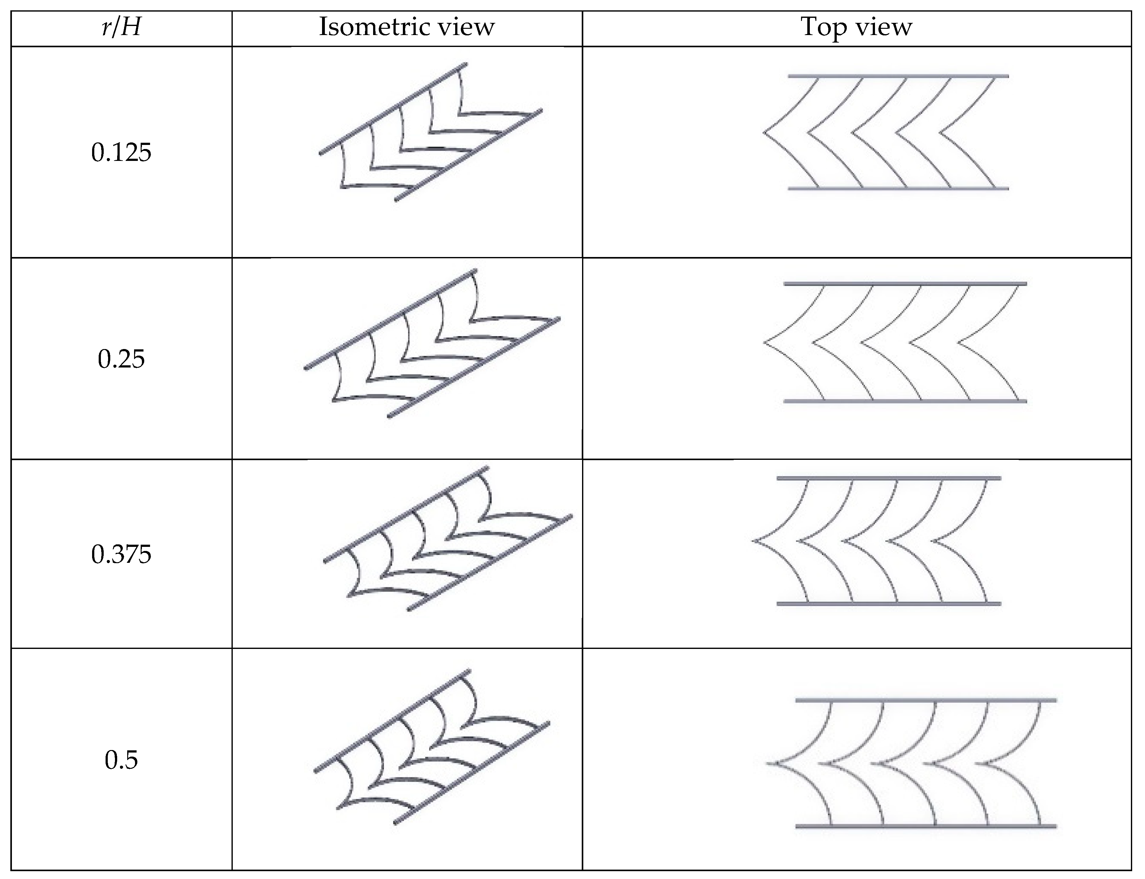
  • The influence of various arc-vane baffle designs (r/H = of 0.125, 0.25, 0.375, and 0.5) on flow patterns and heat transfer behavior at Reynolds numbers between 6000 and 24,000.
  • The potential of arc-vane baffles to generate secondary flows and vortices.
  • The impact of arc-vane baffles on pressure drops, assessing the trade-offs between enhanced heat transfer and increased flow resistance.
  • An evaluation of the thermal performance factor (TPF) as a comparative metric for heat transfer efficiency, benchmarked against exchangers without such inserts.
The findings provide design insights for practical applications in solar air heater systems, contributing to advanced heat transfer enhancement strategies.

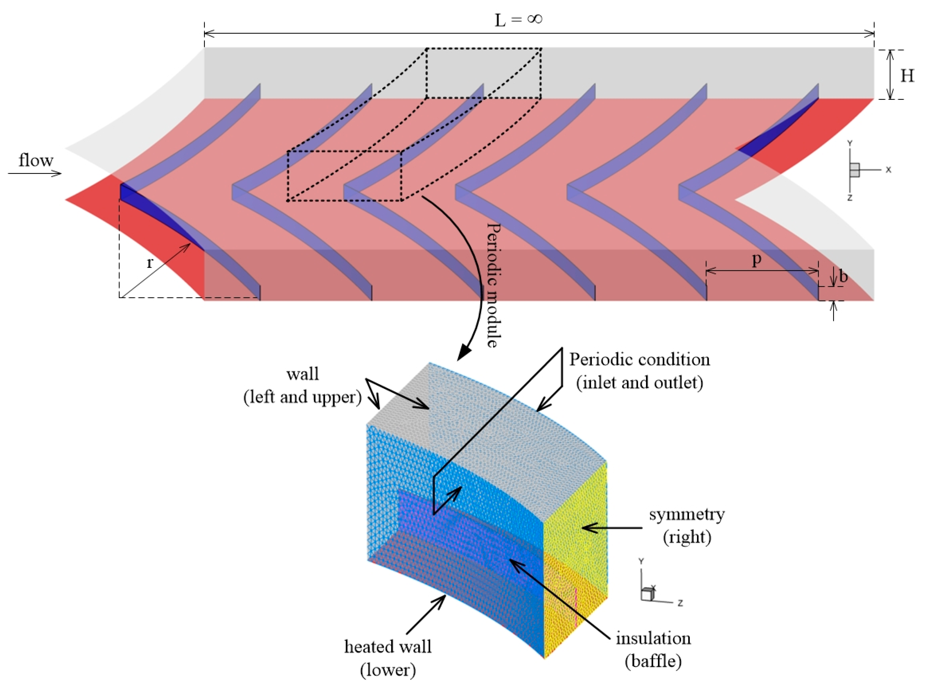
2. Geometry of Arc-Vane Baffles

The geometry of arc-vane baffles is crucial in controlling flow patterns and heat transfer behavior within channels. Previous studies have indicated that the blockage ratio or height-to-diameter ratio (BR, e/H) should be between 0.05 and 0.3 [6]. Higher e/H values around 0.3 yield increased heat transfer rates and pressure drops, resulting in diminished thermal performance factors, whereas lower e/H values around 0.05 yield reduced heat transfer rates and pressure drops, leading to enhanced thermal performance factors. This work concentrates on achieving the highest heat transfer rate; hence, we selected the minimum value of e/H = 0.3. However, an e/H ratio of 0.05 can yield superior thermal performance, as it exhibits a significantly low heat transfer rate and pressure loss. The baffle may be challenging to fabricate or modify for practical applications due to the low e/H ratio.
As shown in Figure 1, the arc-vane baffles are configured with varying radius-to-hydraulic diameter ratios (r/H) of 0.125, 0.25, 0.375, and 0.5 while maintaining a constant height-to-diameter ratio (e/H = 0.3). These baffles are positioned along the channel walls to generate vortices that enhance fluid mixing and reduce thermal resistance near the heated surfaces. The curvature of the baffles significantly influences the intensity and size of these vortices. The selected range of r/H values enables a systematic investigation of how baffle curvature affects flow characteristics.

3. Numerical Method

The computational domain for arc-vane baffles is characterized by the boundary conditions depicted in Figure 1 and Figure 2. Three-dimensional numerical simulations of fluid flow and heat transfer processes in a channel with arc-vane baffles were performed. The current finite differential methods for longitudinal vortex flow and boundary layers were utilized to resolve the governing partial differential equations based on the following assumptions: (1) a steady three-dimensional fluid flow and heat transfer; (2) the flow will be turbulent and incompressible; (3) the fluid properties will be constant; and (4) the natural convection and thermal radiation will be disregarded. According to the above approximations, the subsequent governing differential equations were utilized for the simulation. The equations of continuity (Equation (1)), momentum (Equation (2)), and energy (Equation (4)) for fluid flow are provided as follows.
Continuity equation:
x i u i = 0
Momentum equation:
x j ρ u i u j = P x i + x j μ u i x j ρ u i u j ¯
Energy equation:
x i ρ u i T = x j Γ + Γ t T x j
The term “ ρ u i u j ¯ ” in Equation (2) represents the Reynolds stresses, which can be expressed as follows:
ρ u i u j ¯ = μ t u i x j + u j x i 2 3 ρ k + μ t u i x i δ ij
To resolve the problem, the turbulence model with RNG k-ε was performed. The k and ε transport equations are shown below
for k
ρ k t + ρ k u j x j = x j α k μ eff k x j + G k + G b ρ ε Y M + S k
and for ε
ρ ε t + ρ ε u j x j = x j α ε μ eff ε x j + C 1 ε ε k G k + C 3 ε G b C 2 ε ρ ε 2 k R ε + S ε
In this study, to achieve accurate predictions, a near-wall model with enhanced wall treatment (EWT) was applied to resolve the near-wall region, where solution variables were significantly influenced by large gradients. The near-wall mesh was applied as y+ ≈ 1, where y + = u * y ρ / μ and u * = τ 0 / ρ are the distance from the center of the first near-wall cell to the wall and friction velocity, respectively. The parameters y and τo are the height of the wall-to-wall adjacent cell and wall shear stress, respectively.
The finite volume method was used to discretize the turbulence model and the time-independent incompressible Navier–Stokes equations. The QUICK (Quadratic Upstream Interpolation for Convective Kinetics) differencing scheme [43,44] was applied for the convective and diffusive terms. The discretized nonlinear equations were solved implicitly. The SIMPLE (Semi-Implicit Method for Pressure-Linked Equations) algorithm was employed for pressure–velocity coupling to evaluate the pressure field [45]. A uniform velocity profile was imposed at the inlet. The tube wall was subjected to an impermeable boundary condition, while the lower wall of the test section was assigned a constant heat flux condition. The under-relaxation factors for pressure and momentum were set to 0.4 and 0.6, respectively. The convergence criterion required the residuals of the continuity, momentum, and energy equations were set to be less than 10−6. The turbulence intensity at the inlet was maintained at 10%. Each simulation required approximately 5000 iterations to reach convergence, with a computational time of around 30–50 min per case.
A grid-independence approach was executed utilizing the Richardson extrapolation method across grids with varying number of cells. The tetrahedral grid was employed for meshing (Figure 2). Dense grids were utilized for calculations adjacent to the channel wall and in the proximity of the arc-vane baffle. The grid independence test was conducted with the RNG k-ε turbulent model with different grid sizes with a Reynolds number of 6000. The findings indicate that the simulations possessing adequate density with 500,852 cells lead to a variation in the Nusselt number of less than 1.0%. For r/H values of 0.25, 0.375, and 0.5, the total number of elements utilized is roughly 501,548 cells, 503,214 cells, 506,421 cells, and 503,127 cells, respectively, which are adequate for the current numerical analysis. A triangular mesh with a grid adoption of y+ < 1.0 (refined mesh density) was utilized to resolve the laminar sub-layer (y+ < 5.0) adjacent to the tube wall.
Figure 2 shows details of the computational domain with periodic boundary conditions applied to simulate fully developed flow throughout the channel. Table 1 provides a summary of the air properties and boundary conditions. The inlet air temperature is set to a constant value of 300 K, with the assumption that the air enters the channel uniformly. The lower wall of the channel is exposed to a constant heat flux of 600 W/m2, ensuring consistent heat transfer across the heated surface, as detailed in Table 1. The remaining walls, including the baffle surfaces, are modeled as adiabatic.

4. Data Reduction

The airflow regime is determined by the Reynolds number, which is expressed as follows:
R e = ρ u ¯ D h μ
where u ¯ is the mean velocity and D h = 4 A c / P c is the hydraulic diameter, and A c and P c are the cross-sectional area and wetted perimeter.
The friction factor is determined by utilizing the pressure gradient as follows:
f = d P / d x D h 0.5 ρ u 2 ¯
Newton’s law of cooling is as follows:
q conv = h ( T w T m )
and
q conv = q input
The coefficient of convection heat transfer can be expressed as follows:
h = q input / ( T w T m )
where Tw and Tm are the mean air temperature and wall temperature (heated wall side).
The local Nusselt number is as follows:
Nux = hxDh
The average Nusselt number is as follows:
N u = 1 A N u x d A
The thermal performance factor (TPF) is the ratio of heat transfer enhancement to pressure drop, comparing an enhancing device (arc-vane baffles) with a smooth channel to a channel at constant pumping power. The benefits of heat transfer are balanced against the drawbacks of pressure loss using the TPF criterion. The thermal performance factor can be evaluated based on references [46,47].
For a constant pumping power,
( V ˙ Δ P ) p = ( V ˙ Δ P ) t
The same pumping power relationship can be rewritten in terms of its Reynolds number (Re) and friction factor (f) as follows:
(fRe3)s = (fRe3)t
From Equations (14) and (15), the TPF can be determined as follows:
T P F = N u N u s 1 / 3 f f s
where Nus and fs represent the Nusselt number and the friction factor for a smooth channel, respectively. The relationship between heat transfer enhancement (Nu/Nus) and pressure drop (f/fs) is often characterized by a trade-off. Generally, strategies to enhance heat transfer, such as increasing surface area (e.g., through the use of fins, turbulators, or surface roughness) often result in higher pressure drops. This is because the increased surface area leads to greater friction and flow resistance. However, this trade-off can be mitigated by optimizing the system design, such as selecting appropriate materials or configurations that balance both heat transfer and pressure drop.

5. Numerical Results Analysis

5.1. Verification of the Experimental Setup

A validation test was conducted by comparing the current numerical data for a smooth channel and those obtained from conventional correlations, namely the Dittus–Boelter and Gnielinski correlations for the Nusselt number (Nu) and the Petukhov and Blasius correlations for the friction factor (f) [48]. The comparisons shown in Figure 3a,b suggest that the current results are closely aligned with those obtained from the conventional correlations, with maximum differences of 7.4% and 9.6% for Nu and f, respectively. These results indicate that the current computational setup is acceptable.
Nusselt number correlation for a plain tube by Dittus-Boelter:
N u = 0.023 R e 0.8 P r 0.4
Validity: Re > 10,000, 0.6 < Pr < 160, L/D > 10.
Nusselt number correlation for a plain tube by Gnielinski:
N u = f / 8 R e 1000 P r 1 + 12.7 f / 8 P r 0.66 1
Validity: 3000 < Re < 5 × 10⁶, 0.5 < Pr < 2000.
Friction factor correlation for a plain tube by Petukhov:
f = 0.79 l n R e 1.64 2
Validity: 3000 ≤ Re ≤ 5 × 10⁶, 0.5 < Pr < 2000, L/D ≥ 10.
Friction factor correlation for a plain tube by Blasius:
f = 0.316Re−0.25
Validity: 3000 < Re ≤ 2 × 10⁴.

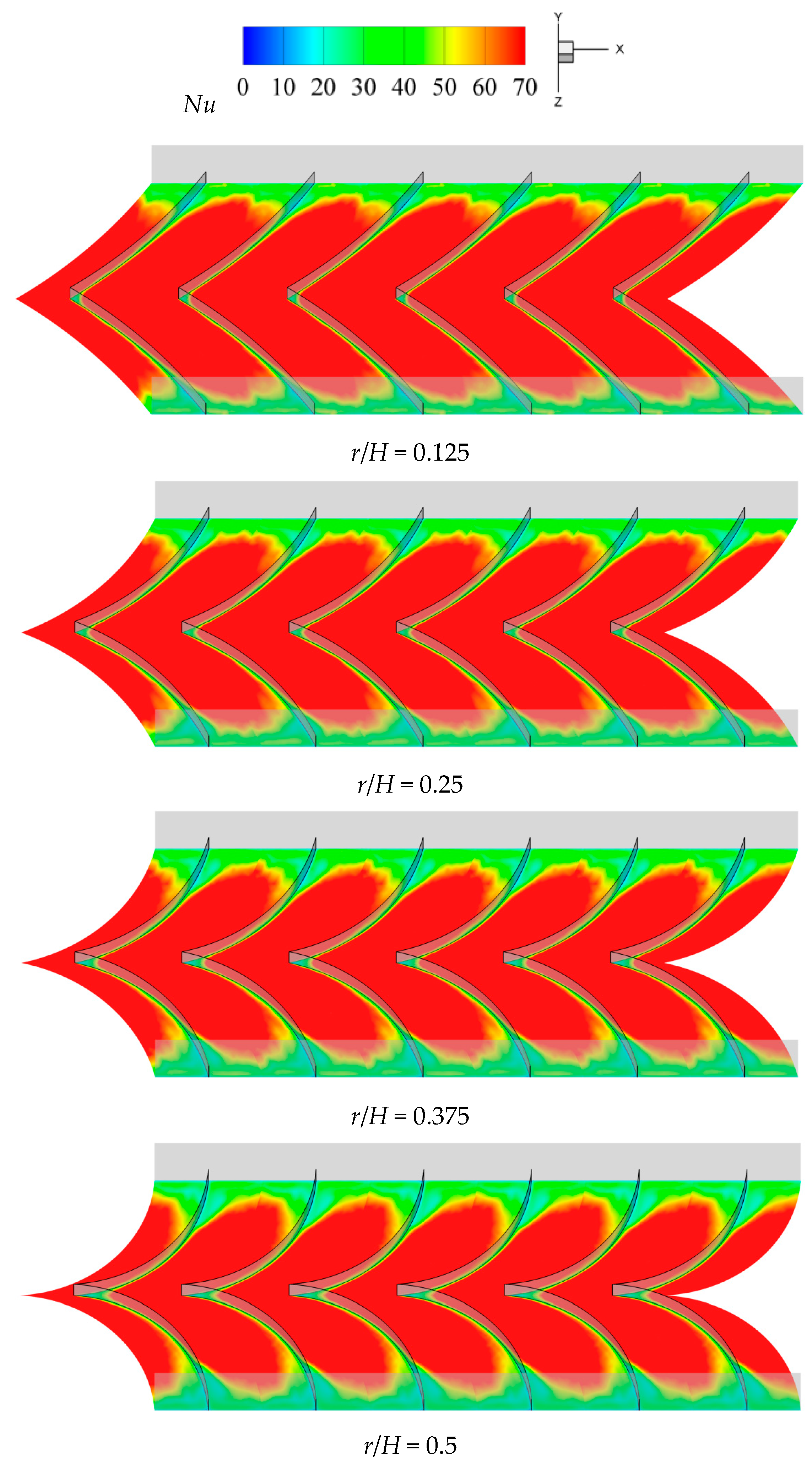
5.2. Heat Transfer and Fluid Flow Mechanisms

The presence and geometric design of arc-vane baffles significantly affect the heat transfer and fluid flow mechanisms within the channel. This influence is evident in the temperature and Nusselt number distributions, as well as the flow patterns shown in Figure 4 and Figure 5. The temperature distributions in Figure 4 demonstrate that arc-vane baffles with smaller r/H ratios tend to create larger regions of lower wall temperature, highlighting a more effective cooling effect. This enhanced cooling is achieved by the influence of these baffles on the flow dynamics within the channel. Specifically, the broader apex of smaller r/H baffles facilitates accessible flow reattachment, increasing fluid mixing near the wall and enhancing fluid–wall interactions. These greater interactions promote heat transfer, as reflected in the wider high-Nu (Nusselt number) regions displayed in Figure 5. The Nusselt number, a measure of convective heat transfer, is more extensive in these areas, underscoring the effectiveness of these baffles in transferring heat from the wall. On the other hand, arc-vane baffles with a larger r/H, due to their narrower apex, limit the reattachment of the flow, reducing contact between the fluid and wall surface. This limited reattachment results in smaller lower-temperature regions and narrower high-Nu zones, interpreting less efficient heat transfer. This difference in performance between baffle designs with varying r/H ratios underscores the importance of baffle curvature in optimizing cooling by controlling flow behavior within the channel.
Figure 6 offers deeper insights into the 3D flow structure and local wall temperature distributions at r/H ratios of 0.125, 0.25, 0.375, and 0.5. The streamline and temperature distributions in cross-sectional planes at various locations are presented: in front of the baffle apex (P1), at the baffle apex (P2), around the middle of the baffle (P3P4), and near the baffle base (P5). The streamline results indicate that the arc-vane baffle generates double vortices along the axial direction, leading to flow reattachment on the heated surface, particularly in the P2–P4 regions. In contrast, flow separations are observed in the P1 and P5 regions, especially near the channel edges. These findings align with the temperature distribution, showing lower temperatures in the P2P4 zones and significantly higher temperatures near the channel edges in the P1 and P5 zones, as highlighted by the dashed envelope. The weaker reattachment in P1 may be attributed to the initial phase of the reattachment process, while the weaker reattachment in the P5 region is likely due to vortex decay as it moves downstream, gradually losing its intensity.
At lower r/H ratios, flow reattachment is more intense, effectively disrupting the thermal boundary layer along the heated wall. This disruption enhances heat transfer by allowing for cooler fluid from the channel core to replace the warmer fluid near the wall, accelerating the cooling process. In contrast, at higher r/H ratios, larger dead zones or regions inaccessible to vortex reattachment emerge. These zones hinder the breakdown of the thermal boundary layer, as the less energetic flow fails to reach the wall. As a result, heat transfer becomes less efficient, as reflected in the Nusselt number distributions in Figure 5, where higher r/H ratios correspond to lower Nu values, indicating reduced heat transfer effectiveness.
Among all of the tested configurations, the smallest r/H ratio of 0.125 provides the best heat transfer performance. This configuration maximizes vortex activity and fluid–wall interactions, leading to greater thermal boundary layer disruption and higher Nusselt values throughout the channel. These findings emphasize the critical role of the r/H ratio in optimizing baffle performance for heat transfer enhancement.

5.3. Overall Performance Evaluation

To evaluate the overall performance of a heat transfer enhancement technique, it is essential to consider both the improved heat transfer and the associated friction loss penalty. The improved heat transfer is commonly represented by the average Nusselt number (Nu) and the Nusselt number ratio (Nu/Nus), which is defined as the ratio of the average Nusselt number for the enhanced technique to that of a smooth channel. Similarly, the friction loss penalty is typically indicated by the friction factor (f) and the friction factor ratio (f/fs). Figure 7a,b shows the Nusselt number (Nu) and Nusselt number ratio (Nu/Nus) of arc-vane baffles with r/H values of 0.125, 0.25, 0.375, and 0.5. They are plotted against the Reynolds number (Re), which can be seen in Figure 7a. The arc-vane baffles significantly enhance heat transfer compared to a smooth channel. The figure illustrates that Nu/Nus generally falls as Re increases. Using arc-vane baffles significantly increases the Nusselt number compared to a smooth channel. This effect is known as common-flow-down vortices, and it is mostly caused by arc-vane baffles, which are shown in Figure 6 and are used to create two internal vortices that rotate counterclockwise. This may result in the formation of multiple impinging jets on the channel surface area behind the arc-vane baffles. The vortices are strengthened and reattached as a result of the prolonged flow residence time, the cessation of thermal boundary layer development, and the rapid merging of the fluids. These methods can lead to a substantial increase in the heat transfer rate.
As illustrated in Figure 7, introducing arc-vane baffles substantially increases the Nusselt number (Nu), with the Nu/Nus ratio exceeding 2.0 across all cases. Additionally, Nu rises as r/H values decrease. This increase is due to the intensified vortex structures generated at smaller r/H ratios, which effectively disrupt the thermal boundary layer and enhance convective heat transfer, as discussed in Section 5.2. Figure 6 also shows that Re increases, the inherent turbulence in the flow becomes more dominant, and the relative contribution of the baffles to heat transfer diminishes. The maximum Nu/Nus ratio, reaching as high as 4.91, occurs at an r/H value of 0.125 and a Reynolds number of 6000.
It was found that turbulence intensity, strong fluid contact with the channel wall, and fast fluid mixing make arc-vane baffles with radius-to-hydraulic diameter ratios (r/H) of 0.125, 0.25, 0.375, and 0.5 much better at moving heat. Concurrently, the turbulence intensity induces an increase in flow friction, which leads to a pressure loss penalty. Thus, the friction factor (f) and friction factor ratio (f/fs) are used to examine the effects of arc-vane baffles on pressure loss, as illustrated in Figure 8a,b. Figure 8 illustrates that the friction factor and friction factor ratio increase as the r/H ratio rises. The primary reason for this increased friction loss is that, with a higher r/H ratio, the curvature and surface area of each baffle increase. The larger surface area creates more obstruction within the channel, which intensifies flow blockage, leading to greater resistance and a corresponding increase in pressure loss and thus friction loss. The flow obstruction due to increased baffle surface area forces the fluid to negotiate around the baffles with higher difficulty, thus contributing to energy dissipation as the fluid overcomes these flow restrictions. Additionally, baffles with larger r/H ratios create larger dead zones, as discussed in Section 5.2, which further contribute to friction losses within the channel. For the range studied, baffles with r/H ratios of 0.125, 0.25, 0.375, and 0.5 yield friction factor ratios (f/fs) in the ranges of 9.36–9.93, 9.73–10.31, 10.51–11.08, and 11.71–12.38, respectively. The thermal performance factor (TPF), as depicted in Figure 9, offers a comprehensive assessment of the system’s performance by considering both heat transfer and friction losses.
A TPF greater than unity indicates that the arc-vane baffles improve the overall thermal performance of the channel, balancing the benefits of enhanced heat transfer against the cost of increased friction. This suggests that using arc-vane baffles leads to overall energy savings. As illustrated in Figure 9, the arc-vane baffles with smaller r/H values deliver higher TPF values, particularly at lower Reynolds numbers. The superior TPF at smaller r/H is attributed to better heat transfer and lower friction loss penalty, as previously described. At r/H = 0.125, the TPF reaches a maximum of 2.28, reflecting the optimal balance between high heat transfer and manageable friction losses. However, as Re increases, the TPF for all configurations gradually decreases, indicating that the friction penalties begin to outweigh the heat transfer gains at higher flow rates. Even at higher Re, lower r/H values consistently outperform larger configurations, with the TPF for r/H = 0.5 remaining below that of the smaller baffles across all flow conditions. This trend emphasizes the effectiveness of baffles with smaller r/H values in achieving an optimal balance between heat transfer and friction loss, particularly within low-to-moderate Reynolds numbers.

6. Comparison with Related Works

Figure 10 presents a benchmark comparison of the thermal performance factors (TPF) for arc-vane baffles at r/H = 0.125 and 0.5 against values reported in relevant studies including various designs of modified baffles. These designs encompass square-wing perforated transverse baffles [49], inclined perforated baffles [50], inline and staggered perforated baffles [51], staggered and partially tilted perforated baffles [23], and V-shaped perforated baffles [52]. The benchmarking results show that the present work with r/H = 0.125 achieves high thermal performance factor (TPF) values. A comparison with the inclined perforated baffles [50] reveals that their TPF is higher in the Reynolds number range of 6000–8000, but lower in the range of 8000–24,000. Additionally, their TPF surpasses that of the square-wing perforated transverse baffles [49], inline/staggered perforated baffles [51], staggered and partially tilted perforated baffles [23], and V-shaped perforated baffles [52].

7. Conclusions

This numerical study assesses the enhancement of thermal performance in a channel equipped with arc-vane baffles. This study focuses on the impact of the radius-to-channel height ratio (r/H) on the flow dynamics and heat transfer characteristics. The key findings are summarized as follows:
  • An arc-vane baffle generates double vortices along the axial direction, causing flow reattachment on the heated surface and resulting in a significant enhancement in heat transfer.
  • The baffles with smaller r/H ratios generate stronger flow reattachment and improve fluid contact with heat transfer surfaces, as evidenced by reduced dead zone areas. The ones with the smallest r/H yield a Nu/Nus ratio of up to 4.91 at the lowest Reynolds numbers (Re) of 6000.
  • The friction factor and friction factor ratio increase as the r/H ratio rises, attributed to the greater curvature and surface area of each baffle, which creates more flow obstruction within the channel.
  • The arc-vane baffles with r/H = 0.125 offer TPF greater than unity across the studied Re (6000 ≤ Re ≤ 24,000). Within the range studied, the TPF reaches a maximum of 2.28 at r/H = 0.125 and Re = 6000, reflecting the optimal balance between high heat transfer and manageable friction losses. This suggests that using the arc-vane baffles leads to overall energy savings.
  • The arc-vane baffles with varying r/H ratios significantly influence heat transfer, pressure drop, and thermal performance characteristics, requiring size optimization for future development. In future work, we can attempt to modify the arc-vane baffles at r/H = 0.125 to decrease the pressure drop while enhancing the thermal performance factor by incorporating a hole in the baffle to promote enhanced fluid mixing between the fluid in the channel and the hot channel wall.

Author Contributions

P.T.; Led the project with conceptualization, methodology, validation, data investigation, resource management, and writing. Also, provided critical input during the review and editing process, created visualizations, and supervised the project. A.P.; Provided formal analysis and contributed to the initial drafts of the manuscript. K.W.; Conducted formal analysis and contributed to the early drafts of the manuscript. N.M.; Collaborated in conceptualization, methodology development, and investigations. M.H.; Collaborated in conceptualization, methodology development, and investigations. V.C.; Validated the findings, contributed to the initial manuscript drafts, provided supervision, and secured funding for the project. S.E.-a.; Collaborated in conceptualization, methodology development, and investigations. All authors have read and agreed to the published version of the manuscript.

Funding

This research was funded by School of Engineering, King Mongkut’s Institute of Technology Ladkrabang (KMITL), received funding support from the NSRF [FRB660065/0258-RE-KRIS/RE-KRIS/FF66/43] And The APC was funded by School of Engineering, King Mongkut’s Institute of Technology Ladkrabang (KMITL).

Data Availability Statement

Data will be made available on request.

Acknowledgments

This research on the ‘Numerical Methodology for Enhancing Heat Transfer in a Channel with Arc-Vane Baffles’ by the School of Engineering, King Mongkut’s Institute of Technology Ladkrabang (KMITL), received funding support from the NSRF (FRB660065/0258-RE-KRIS/RE-KRIS/FF66/43).

Conflicts of Interest

The authors declared no conflict of interest with anyone for submitting/publishing of this manuscript.

Nomenclature

Aheat transfer area, mm2
Accross-section area, mm2
BRblockage ratio, dimensionless
Dhhydraulic diameter, mm
ebaffle height, mm
ffriction factor, dimensionless
fsfriction factor for the smooth channel
Gkgeneration of turbulent kinetic energy, m2s−3
Hchannel height, mm
hconvective heat transfer coefficient, W m−2 K−1
kturbulent kinetic energy, m2 s–2
Lchannel length, mm
Nuaverage Nusselt number, dimensionless
Nusaverage Nusselt number for smooth channel, dimensionless
ΔPstatic pressure, Pa
Pbaffle pitch, m
Pcwetted perimeter, m
PrPrandtl number, dimensionless
q conv convection heat flux, W m−2
q input heat flux input, W m−2
rradius of arc-vane baffle, mm
ReReynolds number, dimensionless
Ttemperature, K
Tmaverage air temperature, K
Twwall temperature, K
TPFthermal performance factor, dimensionless
uvelocity, m s−1
u ¯ mean velocity, m s−1
u * friction velocity, m2 s–2
yy–position or distance from the wall, mm
y+distance from the first near-wall cell center to the wall, dimensionless
Greek letters
μdynamic viscosity, kg s−1 m−1
μtturbulent dynamic viscosity, kg s−1 m−1
Γmolecular thermal diffusivity, kg s−1 m−1
Γtturbulent thermal diffusivity, kg s−1 m−1
εturbulent dissipation rate, m2 s–3
ρdensity, kg m−3
τ w wall shear stress, N m–2
Subscripts
swithout turbulator/smooth channel
tturbulator component
aair

References

  1. Bhowmick, S.; Roy, L.R.; Xu, F.; Saha, S.C. Natural convection fluid flow and heat transfer in a valley-shaped cavity. Computation 2024, 12, 146. [Google Scholar] [CrossRef]
  2. Chamoli, S.; Lu, R.; Yu, P. Thermal characteristic of a turbulent flow through a circular tube fitted with perforated vortex generator inserts. Appl. Therm. Eng. 2017, 121, 1117–1134. [Google Scholar] [CrossRef]
  3. Reddy, G.J.; Kumar, V.G.; Kumar, M.A. The pdepe solver for analysing the flow of MHD Cu–H2O nanofluid across an oscillating vertical plate. Case Stud. Chem. Environ. Eng. 2024, 10, 100910. [Google Scholar]
  4. Wan, T.; Zhao, P.; Chen, Z.; Jin, Y.; Li, Y.; Peng, C. Study of the hydraulic roughness impact on turbulent heat transfer at supercritical pressure based on a fast direct numerical simulation method. Int. J. Heat. Mass. Transf. 2023, 217, 124647. [Google Scholar] [CrossRef]
  5. Ayoob, H.W.; Omar, I.; Ghanim, W.K.; Fares, M.N.; Fazilati, M.A.; Salahshour, S.; Esmaeili, S. The thermal-flow performance of water-Al2O3 nanofluid flow in an elliptical duct heat exchanger equipped with two rotating twisted tapes. Case Stud. Chem. Environ. Eng. 2025, 11, 101094. [Google Scholar] [CrossRef]
  6. Thianpong, C.; Promvonge, P.; Skullong, S.; Promthaisong, P.; Nakhchi, M.E. Numerical heat transfer study of square duct equipped with novel flapped V-baffles. Int. J. Therm. Sci. 2024, 197, 108819. [Google Scholar] [CrossRef]
  7. Bezbaruah, P.J.; Das, R.S.; Sarkar, B.K. Experimental and numerical analysis of solar air heater accoutered with modified conical vortex generators in a staggered fashion. Renew. Energy 2021, 180, 109–131. [Google Scholar] [CrossRef]
  8. Guérin, L.; Flageul, C.; Cordier, L.; Grieu, S.; Agostini, L. Preferential enhancement of convective heat transfer over drag via near-wall turbulence manipulation using spanwise wall oscillations. Int. J. Heat. Fluid. Fl. 2024, 110, 109564. [Google Scholar] [CrossRef]
  9. Poncet, C.; Ferrouillat, S.; Vignal, L.; Courouble, A.; Bulliard-Sauret, O.; Gondrexon, N. Ultrasonically-enhanced convective heat transfer: Evidence of a relationship with the thermal boundary layer. Appl. Therm. Eng. 2022, 216, 119069. [Google Scholar] [CrossRef]
  10. Patankar, S.V.; Liu, C.H.; Sparrow, E.M. Fully developed flow and heat transfer in ducts having streamwise-periodic variations of cross-sectional area. J. Heat. Transf. 1977, 99, 180–186. [Google Scholar] [CrossRef]
  11. Kelkar, K.M.; Patankar, S.V. Numerical prediction of flow and heat transfer in a parallel plate channel with staggered fins. J. Heat. Transf. 1987, 109, 25–30. [Google Scholar] [CrossRef]
  12. Webb, B.W.; Ramadhyani, S. Conjugate heat transfer in a channel with staggered ribs. Int. J. Heat. Mass. Transf. 1985, 28, 1679–1687. [Google Scholar] [CrossRef]
  13. Wu, H.; Yang, S.; Wang, E.; Cao, R.; Fernandes, A.C.; Yin, X.; Xiao, Q. Three-dimensional numerical analysis of a vertical axis autorotation current turbine (VAACT): Effects of lateral blockage and free surface. Appl. Ocean. Res. 2024, 150, 104138. [Google Scholar] [CrossRef]
  14. Salmi, M.; Menni, Y.; Chamkha, A.J.; Ameur, H.; Maouedj, R.; Youcef, A. CFD-Based simulation and analysis of hydrothermal aspects in solar channel heat exchangers with various designed vortex generators. Comput. Model. Eng. Sci. 2020, 126, 147–173. [Google Scholar]
  15. Ejaz, F.; Qasem, N.A.A.; Zubair, S.M. Thermal-hydraulic analysis of wetted airside plain fin flat tube heat exchangers and the role of vortex generators. Appl. Therm. Eng. 2024, 258, 124651. [Google Scholar] [CrossRef]
  16. Ding, J.; Zhao, Z.; Liu, X.; Li, C.; Pu, X. Buoyancy influences on local heat transfer characteristic of supercritical LNG across the pseudo-phase transition in variable cross-section horizontal channels. Appl. Therm. Eng. 2024, 245, 122823. [Google Scholar] [CrossRef]
  17. Ran, S.; Zhang, P.; Rao, Y. Numerical study of heat transfer and flow structure over channel surfaces featuring miniature V rib-dimples with various configurations. Int. J. Therm. Sci. 2021, 172, 107342. [Google Scholar] [CrossRef]
  18. Yuan, Z.X.; Tao, W.Q.; Wang, Q.W. Numerical prediction for laminar forced convection heat transfer in parallel-plate channels with streamwise-periodic rod disturbances. Int. J. Numer. Methods Fluids 1998, 28, 1371–1387. [Google Scholar] [CrossRef]
  19. Young, T.J.; Vafai, K. Convective cooling of a heated obstacle in a channel. Int. J. Heat. Mass. Transf. 1998, 41, 3131–3148. [Google Scholar] [CrossRef]
  20. Promvonge, P.; Promthaisong, P.; Skullong, S. Heat transfer augmentation in solar heat exchanger duct with louver-punched V-baffles. Sol. Energy 2022, 248, 103–120. [Google Scholar] [CrossRef]
  21. Mohit, M.K.; Gupta, R. Numerical investigation of the performance of rectangular micro-channel equipped with micro-pin-fin, Case. Stud. Therm. Eng. 2022, 32, 101884. [Google Scholar] [CrossRef]
  22. Jayranaiwachira, N.; Promvonge, P.; Promthaisong, P.; Nakhchi, M.E.; Skullong, S. Heat transfer analysis in a tube contained with louver-punched triangular baffles. Results Eng. 2024, 22, 102276. [Google Scholar] [CrossRef]
  23. Habet, M.A.E.; Ahmed, S.A.; Saleh, M.A. The effect of using staggered and partially tilted perforated baffles on heat transfer and flow characteristics in a rectangular channel. Int. J. Therm. Sci. 2021, 174, 107422. [Google Scholar] [CrossRef]
  24. Zhang, P.; Xu, C.; Rao, Y.; Liang, C. Experimental and numerical study of heat transfer and turbulent flow in a rotating channel with V rib-dimple hybrid structures. Int. J. Therm. Sci. 2023, 187, 108162. [Google Scholar] [CrossRef]
  25. Yadav, A.S.; Bhagoria, J.L. A CFD (computational fluid dynamics) based heat transfer and fluid flow analysis of a solar air heater provided with circular transverse wire rib roughness on the absorber plate. Energy 2013, 55, 1127–1142. [Google Scholar] [CrossRef]
  26. Yadav, A.S.; Bhagoria, J.L. A CFD based thermo-hydraulic performance analysis of an artificially roughened solar air heater having equilateral triangular sectioned rib roughness on the absorber plate. Int. J. Heat. Mass. Transf. 2013, 70, 1016–1039. [Google Scholar] [CrossRef]
  27. Zhang, P.; Xia, P.; Guo, X.; Xie, S.; Ma, W. A CFD-adjoint reverse design of transverse rib profile for enhancing thermo-hydraulic performance in the solar air heater, Renew. Energy 2022, 198, 587–601. [Google Scholar]
  28. Thakur, D.S.; Khan, M.K.; Pathak, M. Solar air heater with hyperbolic ribs: 3D simulation with experimental validation. Renew. Energy 2017, 113, 357–368. [Google Scholar] [CrossRef]
  29. Misra, R.; Singh, J.; Jain, S.K.; Faujdar, S.; Agrawal, M.; Mishra, A.; Goyal, P.K. Prediction of behavior of triangular solar air heater duct using V-down rib with multiple gaps and turbulence promoters as artificial roughness: A CFD analysis. Int. J. Heat. Mass. Transf. 2020, 162, 120376. [Google Scholar] [CrossRef]
  30. Jamal, I.; Barhdadi, F.Z.; Amghar, K.; Daoudi, S.; Yahiaoui, R.; Ghoumid, K. Enhancing performance in solar air channels: A numerical analysis of turbulent flow and heat transfer with novel shaped baffles. Appl. Therm. Eng. 2024, 251, 123561. [Google Scholar] [CrossRef]
  31. Mahanand, Y.; Senapati, J.R. Thermal enhancement study of a transverse inverted-T shaped ribbed solar air heater. Int. Commun. Heat. Mass. Transf. 2020, 119, 104922. [Google Scholar] [CrossRef]
  32. Li, Y.; Rao, Y.; Wang, D.; Zhang, P.; Wu, X. Heat transfer and pressure loss of turbulent flow in channels with miniature structured ribs on one wall. Int. J. Heat. Mass. Transf. 2018, 131, 584–593. [Google Scholar] [CrossRef]
  33. Jin, D.; Zhang, M.; Wang, P.; Xu, S. Numerical investigation of heat transfer and fluid flow in a solar air heater duct with multi V-shaped ribs on the absorber plate. Energy 2015, 89, 178–190. [Google Scholar] [CrossRef]
  34. Jin, D.; Quan, S.; Zuo, J.; Xu, S. Numerical investigation of heat transfer enhancement in a solar air heater roughened by multiple V-shaped ribs. Renew. Energy 2018, 134, 78–88. [Google Scholar] [CrossRef]
  35. Eiamsa-ard, S.; Suksangpanomrung, A.; Promthaisong, P. Enhanced heat transfer mechanism and flow topology of a channel contained with semi-circular hinged V-shaped baffles. Int. J. Therm. Sci. 2022, 177, 107577. [Google Scholar] [CrossRef]
  36. Menni, Y.; Chamkha, A.; Zidani, C.; Benyoucef, B. Baffle orientation and geometry effects on turbulent heat transfer of a constant property incompressible fluid flow inside a rectangular channel. Int. J. Numer. Methods Heat. Fluid. Flow. 2019, 30, 3027–3052. [Google Scholar] [CrossRef]
  37. Phila, A.; Keaitnukul, W.; Eiamsa-ard, S.; Naphon, P.; Maruyama, N.; Hirota, M.; Chuwattanakul, V. Influence of notched baffles on aerothermal performance behaviors in a channel. Case Stud. Therm. Eng. 2023, 47, 103070. [Google Scholar] [CrossRef]
  38. Phila, A.; Eiamsa-ard, S.; Thianpong, C. Thermal Performance Evaluation of a Channel Installed with Inclined-Baffle Turbulators. Arab. J. Sci. Eng. 2019, 45, 609–621. [Google Scholar] [CrossRef]
  39. Eiamsa-ard, S.; Pattanapipat, S.; Promvonge, P. Influence of triangular wavy baffles on heat and fluid flow characteristics in a channel, J. Mech. Sci. Technol. 2013, 27, 2199–2208. [Google Scholar] [CrossRef]
  40. Rashid, F.L.; Al-Gaheeshi, A.M.R.; Mohammed, H.I.; Ameen, A. Heat convection in a channel-opened cavity with two heated sources and baffle. Energies 2024, 17, 1209–1241. [Google Scholar] [CrossRef]
  41. Rashid, F.L.; Al-Gaheeshi, A.M.R.; Al-Obaidi, M.A.; Mohammed, H.I.; Togun, H.; Agyekum, E.B. Analysing fluid flow and heat transfer comparatively in flow passage systems: Evaluating thermal impacts and geometric configurations. Int. J. Thermofluids 2024, 24, 100894. [Google Scholar] [CrossRef]
  42. Rashid, F.L.; Eleiwi, M.A.; Tahseen, T.A.; Mohammed, H.I.; Tuama, S.A.; Ameen, A.; Agyekum, E.B. Influence of adiabatic semi-circular grooved in backward-facing step on thermal-hydraulic characteristics of nanofluid. Int. J. Thermofluids 2025, 26, 101052. [Google Scholar] [CrossRef]
  43. Matsson, J. An Introduction to ANSYS Fluent 2019; SDC Publications: Mission, KS, USA, 2019. [Google Scholar]
  44. Bender, E. Numerical heat transfer and fluid flow, Von S.V. Patankar, Hemisphere Publishing Corporation, Washington—New York—London McGraw Hill Book Company, New York 1980 1 Aufl, 197 S, 76 Abb, geb, DM 71,90. Chem. Ing. Tech. 1981, 53, 225. [Google Scholar] [CrossRef]
  45. Patankar, S.V. Numerical Heat Transfer and Fluid Flow; Hemisphere Publishing Corporation: Washington, DC, USA, 2018. [Google Scholar]
  46. Promvonge, P.; Skullong, S. Enhanced thermal performance in tubular heat exchanger contained with V-shaped baffles. Appl. Therm. Eng. 2021, 185, 116307. [Google Scholar] [CrossRef]
  47. Promvonge, P.; Skullong, S. Heat transfer in solar receiver heat exchanger with combined punched-V-ribs and chamfer-V-grooves. Int. J. Heat. Mass. Transf. 2019, 143, 118486. [Google Scholar] [CrossRef]
  48. Incropera, F.; Dewitt, P.D. Introduction to Heat Transfer, 5th ed.; John Wiley & Sons Inc.: New York, NY, USA, 2006. [Google Scholar]
  49. Eiamsa-ard, S.; Phila, A.; Pimsarn, M.; Maruyama, N.; Hirota, M. Heat transfer mechanism and thermal performance of a channel with square-wing perforated transverse baffles installed: Effect of square-wing location. J. Therm. Anal. Calorim. 2023, 148, 3835–3849. [Google Scholar] [CrossRef]
  50. Kumar, R.; Nadda, R.; Kumar, S.; Razak, A.; Sharifpure, M.; Aybar, H.S.; Saleel, C.A.; Afzal, A. Influence of artificial roughness parametric variation on thermal performance of solar thermal collector: An experimental study, response surface analysis and ANN modelling. Sustain. Energy Technol. Assess. 2022, 52, 102047. [Google Scholar] [CrossRef]
  51. El Habet, M.A.; Ahmed, S.A.; Saleh, M.A. Thermal/hydraulic characteristics of a rectangular channel with inline/staggered perforated baffles. Int. Commun. Heat. Mass. Transf. 2021, 128, 105591. [Google Scholar] [CrossRef]
  52. Chamoli, S.; Thakur, N.S. Correlations for solar air heater duct with V-shaped perforated baffles as roughness elements on absorber plate. Int. J. Sustain. Energy 2016, 35, 1–20. [Google Scholar] [CrossRef]
Figure 1. Geometry of arc-vane baffles in isometric and top views.
Computation 13 00071 g001
Figure 2. The computational domain and boundary conditions of a channel containing arc-vane baffles.
Computation 13 00071 g002
Figure 3. Comparisons between the current numerical data for a smooth channel and those obtained from conventional correlations.
Computation 13 00071 g003aComputation 13 00071 g003b
Figure 4. Wall temperature distributions on heated surfaces equipped with arc-vane baffles at r/H ratios of 0.125, 0.25, 0.375, and 0.5.
Computation 13 00071 g004
Figure 5. Nusselt number distributions on heated surfaces equipped with arc-vane baffles at r/H ratios of 0.125, 0.25, 0.375, and 0.5.
Computation 13 00071 g005
Figure 6. Streamline and temperature distributions in cross-sectional planes at different r/H ratios.
Computation 13 00071 g006aComputation 13 00071 g006b
Figure 7. Variation in Nu and Nu/Nuₛ with Re for channels equipped with arc-vane baffles at r/H ratios of 0.125, 0.25, 0.375, and 0.5.
Computation 13 00071 g007
Figure 8. Variation in f and f/fs for channels equipped with arc-vane baffles at r/H ratios of 0.125, 0.25, 0.375, and 0.5.
Computation 13 00071 g008
Figure 9. Variation in TPF with Re for channels equipped with arc-vane baffles at r/H ratios of 0.125, 0.25, 0.375, and 0.5.
Computation 13 00071 g009
Figure 10. Graph comparing the thermal performance factors (TPF) of previous studies [23,49,50,51,52].
Computation 13 00071 g010
Table 1. Details of the boundary conditions of a channel fitted with arc-vane baffles.
LocationBoundary TypeConditions
Inlet and outletPeriodic [44]Air enters at 300 K (Pr = 0.707)
Upper wallAdiabatic,
no-slip
No heat transfer through the wall
Lower wallConstant heat flux, no-slipConstant heat flux at 600 W/m2 and no-slip
Left and right wallsSymmetrySymmetry conditions applied
Arc-vane bafflesAdiabatic, no-slipBaffles are thermally insulated, no-slip
Disclaimer/Publisher’s Note: The statements, opinions and data contained in all publications are solely those of the individual author(s) and contributor(s) and not of MDPI and/or the editor(s). MDPI and/or the editor(s) disclaim responsibility for any injury to people or property resulting from any ideas, methods, instructions or products referred to in the content.

