Article

Design and Numerical Simulation of a Standing Surface Acoustic Wave-Based Microdevice for Whole Blood Cell Separation

by
Maryam Hajimoradi
1,
Moein Talebian Gevari
2,
Keith Robert Pullen
3,* and
Mohammad Mojaddam
1,*
1
Faculty of Mechanical and Energy Engineering, Shahid Beheshti University, Tehran 1658953571, Iran
2
Division of Solid-State Electronics, Department of Electrical Engineering, Uppsala University, 75121 Uppsala, Sweden
3
Department of Engineering, School of Science and Technology, City St George’s, University of London, London EC1V 0HB, UK
*
Authors to whom correspondence should be addressed.
Computation 2025, 13(2), 42; https://doi.org/10.3390/computation13020042
Submission received: 19 December 2024 / Revised: 4 February 2025 / Accepted: 4 February 2025 / Published: 6 February 2025
(This article belongs to the Section Computational Engineering)

Abstract

:
Standing surface acoustic wave (SSAW)-based acoustofluidics is widely used due to its compatibility with soft materials and polymer structures. In the presence of an acoustic field, particles move either toward pressure nodes or anti-nodes according to their contrast factor. Using this technique, blood cells with a certain characteristic can be oriented in different streamlines in a microchannel. The cumulative effect of parameters, such as the inlet velocity ratio of the buffer solution to the blood sample, acoustic frequency, voltage, and channel geometry, is key to effective separation in these microfluidic chips. In this study, simultaneous separation of white blood cells, red blood cells, and platelets in one stage is simulated by means of numerical calculations. The linear constitutive equation for the piezoelectric substrate, the Helmholtz equation for the acoustic field, and the Navier–Stokes equations for fluid mechanics are solved simultaneously to precisely capture the blood cell behavior in the SSAW-based device. The results show that whole blood cell separation can be achieved using a velocity ratio of 6.25, a resonance frequency of 8.28 MHz, and a voltage of 8.5 V in the proposed five-outlet microfluidic chip.

1. Introduction

In many biological terms, it is crucial to separate particles, whether by their electromagnetic properties, i.e., electric charge and magnetic properties, or by their physical characteristics, such size, shape, and density [1,2]. Separation of damaged cells, such as circulating tumor cells (CTCs) [3], malaria-infected cells [4], or bacteria [5], from healthy blood cells are a few examples of the many “separation” applications in biomedical and bioengineering systems. Other examples include the capture of extracellular vesicles (as submicron particles carrying RNA and proteins) from other blood components [6], blood plasma separation from undiluted blood [7], and setting apart normal sperms from non-motile sperms to boost the success rate of in vitro fertilization (IVF) [8].
Blood cell separation is one of the most critical steps for clinical diagnosis of blood cell-related diseases (e.g., hemophilia and HIV), as well as for further studies on blood cells such as the effects of a drug and treatment on one specific population of cells. Blood cells, including white blood cells (WBCs), red blood cells (RBCs), and platelets (PLTs), form about 45% of the whole blood [9]. Each blood cell plays an important role. RBCs make up 95% of total blood cells and contain hemoglobin, which carries oxygen to the body’s tissues; WBCs are the largest blood cells, making up less than 1% of blood cells and involving in fighting infection as part of the immune system; and PLTs make up about 4.9% of blood cells. They stop bleeding by forming a clot at the bleeding site [10,11,12]. Any observation that detects an abnormal amount of any of these cells in the blood could be an indication of a particular disease. For instance, by separating and counting the number of WBCs in a blood sample, it is possible to diagnose human immunodeficiency virus (HIV) [13].
Microfluidics has gained ground in the last two decades with a close clinical prospect. It is a promising field due to its versatility, ease of use, accuracy, and tiny sample volume consumption, as opposed to conventional methods, which are time-consuming in the diagnosis process and require higher costs [1,2,14]. Microfluidics is vastly implemented in droplet generation [15,16], lab-on-a-chip and lab-on-a-disk [17,18], organ-on-a-chip [19], particle focusing, manipulating [20,21], mixing [22], and drug delivery [23,24]. Microfluidics brings about a better and more efficient performance in particle separation. Separating particles with microfluidics is classified into two categories: active and passive. Active methods such as di-electrophoresis [25,26], magnetophoresis [27,28], and acoustophoresis [2,29] manipulate particles by exerting external forces. On the other hand, passive methods rely on variable and complex geometries as well as inducing mechanical forces without aid from any external forces. One difficulty in using active methods is the complexity of their structure. Nevertheless, they are more accurate and efficient and provide more controllability in contrast to passive methods like pinched flow fraction [30], inertial focusing in spiral and curved microchannels [31,32,33], and deterministic lateral displacement (DLD) [33,34], which are easier to put in use. Besides these two main categories, another class has emerged as combined or hybrid methods that benefit from both upsides of active and passive techniques [2,14,35].
Acoustofluidics, which integrates acoustophoresis and microfluidics, uses acoustic pressure waves on a micro-scale to manipulate particles. Introducing acoustic waves into microfluidics was a breakthrough due to the high biocompatibility and its capability to separate particles based on their size, density, and compressibility. It is a label-free technique with high sensitivity and offers distinctive advantages [36,37]. This branch of microfluidics has been extensively developed for diverse biofluidic applications [38,39] and seamlessly integrated with other microfluidic chips, enhancing the manipulation of objects like nanoparticles [40].
Surface acoustic waves (SAWs) and bulk acoustic waves (BAWs) are the two main and currently feasible types of acoustic waves in such systems. Previous studies have focused on BAW systems, which are easy to manufacture but require a rigid structural material, such as silicon and/or glass, to reflect the waves. In such devices, the transducer is externally placed at the bottom of the piezoelectric substrate [37]. Dyke et al. separated PLTs from WBCs using a BAW-based microfluidic device that is made of silicon. Particles were separated with a recovery rate of 89% at a resonance frequency of 2 MHz [41]. In 2016, Chen et al. presented a BAW device that isolates PLTs from WBCs and RBCs, with high throughput (10 mL/min) and more than 80% recovery rate [42]. SAWs, on the other hand, can be generated by interdigital transducers (IDTs), and these systems can be made of PDMS [43,44,45,46]. As an example, cancer cells were separated from WBCs with a recovery rate of 83–93% in a tilted-angle SAW device at 19.57 MHz [47]. The device had three inlets and two outlets in this work. The sheath flow was injected through the side inlets, and the blood sample was injected through the middle inlet. By applying voltage using tilted IDTs and forming acoustic pressure field, CTCs and WBCs could be isolated via separate outlets. Shi et al. separated polystyrene particles with the same density but with different diameters (0.87 and 4.17 µm) in a SSAW-based device. The microchannel was made of PDMS with three inlets and three outlets. Since larger particles experience a larger acoustic radiation force (ARF), 4.17 µm polystyrene particles were concentrated in the middle of the microchannel and were separated by the middle outlet. Similarly, smaller particles were isolated via the side outlets, being exerted with a smaller ARF [43].
Meanwhile, several numerical studies have been carried out to gain more insight into system performance and facilitate optimization to increase separation efficiency. A 3D finite element analysis was performed on a BAW configuration to investigate the influence of parameters on system operation [48]. The authors evaluated these influential parameters by setting metrics such as purity, yield, and percentage of stuck particles in the microchannel. Taatizadeh et al. studied an acoustofluidic chip and considered the effect of the thickness and dimensions of the PDMS wall on a SAW-based chip [46]. In another study, a two-stage acoustofluidic chip was designed to separate five different particles throughout nine outlet channels. Particles were focused in the same streamline using ARF to increase efficiency, and then they were separated [49]. Shamloo et al. proposed a new design to isolate blood cells, which can operate in two modes: one when the target cells are PLTs, and another when the target cells are WBCs. Their proposed device cannot simultaneously separate whole blood cells [50].
Despite significant progress in the development of blood cell separation techniques, there remains a gap in research regarding the simultaneous separation of multiple cell types using SAW systems. Current methods often rely on multiple stages or complex processing steps, limiting their efficiency and applicability in clinical settings. In this study, we address this gap by proposing a SAW-based device designed to separate WBCs, RBCs, and PLTs simultaneously in a single stage. This innovation lies in the development of a five-outlet channel design, which enhances the separation process by enabling the effective isolation of multiple blood cell types without the need for multiple stages. In SSAW-based numerical models, the constitutive equation for piezoelectric, i.e., Helmholtz equation, and the Navier–Stokes equations for fluid mechanics must be solved simultaneously to accurately capture the underlying physics. The model developed in this work is verified against previously published data, ensuring an effective replication of the blood cell behavior in an acoustic field. The numerical results are in good agreement with the published experimental studies, confirming the model’s accuracy and providing a powerful tool to further investigate the application of acoustofluidic chips in whole blood cell separation. Finally, utilizing this verified numerical model, a five-outlet channel design is proposed, maintaining the same physical behavior while being optimized for improved separation efficiency. The design incorporates a combination of piezoelectric, acoustic, and fluid mechanics to accurately model and capture the behavior of blood cells within the microchip. A comprehensive parametric study is conducted to explore the impact of critical factors such as shear force, particle exposure time to acoustic waves, and intensity of acoustic pressure fields on the performance of the device. These parameters are optimized to achieve efficient separation while minimizing overlapping and improving throughput.

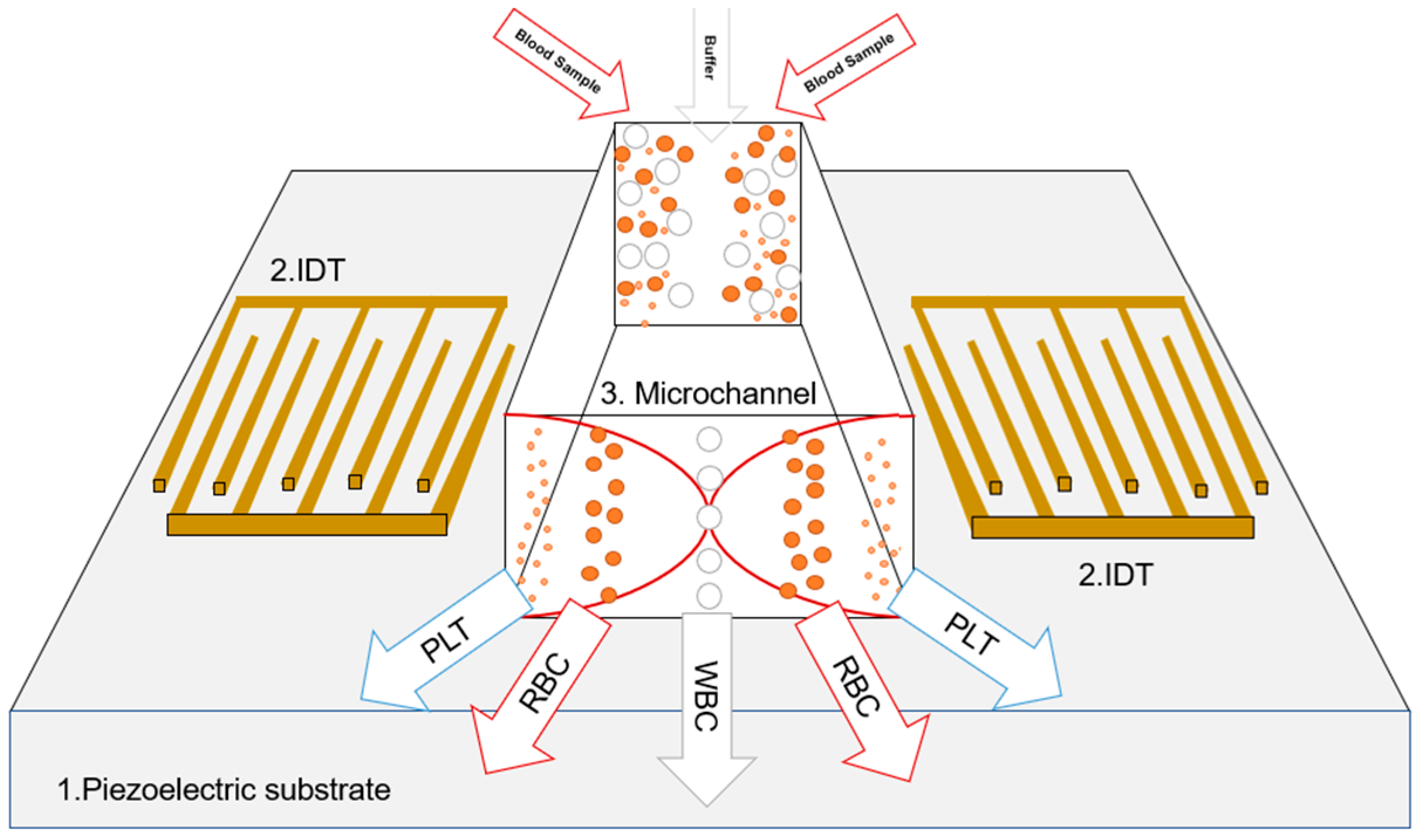
2. SAW-Based Microchips

SAWs propagate on the surface of the piezoelectric material [45] in contrast to BAWs, which propagate through the entire piezoelectric substance [48,51]. SAWs can be actuated using two pairs of comb-shaped electrodes called interdigital transducers (IDTs); see Figure 1. Each electrode generates a traveling surface acoustic wave (TSAW) [52] in opposite directions. The superimposition of two opposite TSAWs forms pressure nodes (PNs) and pressure anti-nodes (PANs) across the microchannel. These kinds of waves are called SAWs. Particles tend to move toward these PNs or PANs based on their contrast factor [37,47].
Figure 1 shows a schematic of a microchannel. A PDMS microchannel is installed on a piezoelectric bed. Standing acoustic waves are generated using two IDTs located on both sides of the channel. The red lines represent the pressure waves. PNs are located in the middle of the microchannel where two waves form a node (p = 0), and PANs are near the wall of the channel.
The contrast factor ( ϕ ) is a function of the density and compressibility of particles and their medium. A negative contrast factor means particles tend to move toward PANs, while particles with a positive contract factor move toward PNs. Once particles with a negative contrast factor enter the microchannel, they accumulate on the PANs where the acoustic pressure reaches its maximum magnitude. However, if the injected particles have a positive contrast factor, they move toward the PNs, where the pressure acoustics are zero.
As most biological particles—in this case, WBCs, RBCs, and PLTs—have a positive contrast factor [6], a SAW-based device is designed in a way that the PNs fall at the center of the channel. Larger particles move faster than smaller ones toward the PNs as the acoustic radiation force (ARF) varies based on the particle size.

2.1. Governing Equations

The contrast factor ( ϕ ) can be calculated using Equation (1) [50]:
ϕ κ , ρ = 5 ρ p 2 ρ f 2 ρ p + ρ f κ p κ f
where ρ and κ represent the density and compressibility, and the subscripts p and f refer to the particles and the fluid, respectively.
By exerting voltage on the IDTs, an electric field is generated, and due to the electromechanical property of Lithium Niobate (LiNbO3) as a piezoelectric substrate, it is possible to excite ultrasound waves in a SAW-based system [2,14]. The linear constitutive equation, which determines the relation between the electric field and the stress, is represented in Equations (2) and (3) [50].
σ = C . ϵ e T . E
D = e . ϵ + ε . E
where σ and C are the mechanical stress tensor and the elasticity matrix of piezoelectric. ϵ is the strain tensor, and e T is the transpose of the piezoelectric coupling matrix that couples the electric field and the mechanical motion. E and D are the electric field vector and the electric displacement vector, respectively, and ε is the dielectric permittivity matrix.
The harmonic Helmholtz equation, shown in Equation (4), is used to determine the acoustic pressure field [46,53].
. 1 ρ k P ω 2 ρ k c k 2 P = 0
ρ k = ρ f c f 2 c k 2 ,      
c k = c f 1 + j ω 4 μ 3 + μ B ρ f c f 2  
where P, c, μ , and μ B are the acoustic pressure, speed of sound, viscosity, and bulk viscosity, respectively. The subscript k is the equivalent property of the medium.
The interaction between the substrate and the microchannel interface is considered a boundary condition in Equation (7), which couples the piezoelectric effects with the acoustic pressure field.
σ n = P . n
As there is a fluid flowing along the microchannel, the momentum equation of an incompressible flow is obtained by Equation (8) [53].
ρ f d u f d t = p + η 2 u f
Two main forces are acting: the drag force and the ARF. The ARF exerted on the particles is determined using Equation (9) [54].
F r a d = U
U = 4 π 3 a 3 f 1 1 2 ρ f c f 2 R e P · P * f 2 3 ρ f 4 R e v · v *
f 1 = 1 κ p κ f
f 2 = 2 ρ p ρ f 2 ρ p + ρ f
The (*) in Equation (10) denotes the complex conjugate and Re[.] represents the real part of the expression. The drag force obtained via Stokes’ law is shown in Equation (13) [55].
F D r a g = 6 π μ a   u u P
where a and u are the radius and velocity, respectively, and u is the time-averaged velocity of the acoustic field.
The relationships between the forces exerted (drag and acoustic radiation) and the application of Newton’s second law allow us to determine the position of each particle within the microchannel.

2.2. Modeling

2.2.1. Geometry and Materials

A schematic of the microfluidic device is shown in Figure 2. The microchannel shape, which is composed of three inlets and five outlets, and its dimensions are shown. The buffer solution and blood samples are injected through the middle and side inlets. The middle outlet is for collecting WBCs, and the outer outlets are for collecting PLTs.
The material and dimension of each part in the setup is presented in Table 1. Also, the properties of each material are presented in Table 2.

2.2.2. Solver Configuration

The simulation of this problem was performed using COMSOL Multiphysics. The laminar flow, solid mechanic, electrostatic, pressure acoustic, and particle tracing modules were used in this study. The solution procedure was carried out as described here. The linear constitutive equations (Equations (1) and (2)) were solved using the solid mechanics and electrostatics for the piezoelectric part. The normal displacement of the longitudinal sides of the substrate was defined as zero. Half of the IDTs were set at ground voltage (V = 0), and the others were set at different voltages to excite SAWs. Pressure acoustics were used to solve the Helmholtz equation.
Since the maximum calculated Reynolds number is around 3.55 in this system, a laminar flow regime is ensured [53]. The boundary condition in the channel interface and the piezoelectric substrate was solved using Equation (7). The outlets were exposed to atmospheric pressure. A no-slip boundary condition was set for the walls. The buffer solution and blood velocities were set to be 75 mm/s and 12 mm/s, respectively.
The particle diameters for PLTs, RBCs, and WBCs are assumed to be 3, 8, and 14 μ m , respectively. The density and compressibility of particles are 1020 k g m 3 and 4 × 10 10   P a 1 , respectively [50].
The mesh of the substrate and the microchannel was set to a maximum element size of 26.3 µm, and the maximum element size of the mesh for IDTs was set to be 55.5 μ m . Other material properties, such as elastic, dielectric, and piezoelectric matrixes, were adopted using the material library available in the COMSOL Multiphysics 6.0.

3. Results and Discussion

3.1. Model Verification

Before going through the results of the modeled setup, the results are verified using a 2D finite element method simulation of a former study conducted by Shamloo et al. [50]. A separator is modeled that operates in two different modes to capture either WBCs or PLTs in each mode. The schematic of the system is shown in Figure 3. The buffer solution is injected through the middle inlet with a velocity of 30 mm/s, and the blood samples are injected through the side inlets with a velocity of 15 mm/s. The applied voltage for separating WBCs from blood is 3 V, and for PLTs, the separation is carried out at 5 V.
At a resonance frequency of 7.453 MHz, as Figure 3 demonstrates, WBCs and PLTs are isolated from the whole blood sample with voltages of 3 V (Figure 3d) and 5 V (Figure 3e), respectively. Moreover, the acoustic pressure profile and its magnitude corresponding to the applied voltages (3 V and 5 V) is shown in Figure 3a–c. The results show good agreement with those of a previous study [50], which reported a resonance frequency of 7.4125 MHZ and a maximum acoustic pressure magnitude of 0.36 and 0.62 MPa for an applied voltage of 3 V and 5 V, respectively. Using the validated results, further studies were performed to investigate the effects of the operational parameters, like inlet velocity ratio, voltage, particle size, channel width, and operating velocity field of the validated model.

3.2. Parametric Study

3.2.1. Inlet Velocity Ratio ( α )

In this section, particles’ deflection along the microchannel is measured against the inlet velocity ratio (buffer solution’s velocity to blood’s velocity). Two different behaviors of particles under different α values are obtained. The main parameter that controls the particle deflection at low inlet velocity ratios is the inadequate drag force. In other words, when the system is operating at a low α due to the lack of sufficient drag force to hold particles back, their deflection is larger compared to when the system is operating at a higher α . As α increases, the deflection increases for a while and reaches its peak. After the rise, for higher ratios, the main reason for particle deflection is ARF; so after that, deflection declines as α increases. Nevertheless, both forces (drag force and ARF) play a role in both stages and increase the main parameter, but one force is more effective in each area. As previously mentioned, the dominant force is the inadequate drag force at a low α up to the peak point, and after the peak, the dominant force that actively affects particle deflection is the ARF (Figure 4).
One explanation for this behavior is that when α = 0 , particles tend to move closer to the center of the channel as their initial position. As particles are exposed to the ARF, they move to the center of the microchannel upon the entrance, minimizing deflection throughout the channel (see Figure 5a,b). When the buffer solution is introduced into the system, it pushes particles away from the center. Hence, their initial position moves away from the center. Due to the inadequate shear force, the ARF aligns the particles toward the center of the microchannel; so, in this part of the observation, by increasing α , the deflection increases too (see Figure 5c,d). This range is not suitable for particle separation, but in the case of buffer exchange, this range is enough.
In the second stage of the plots in Figure 4, as α increases, the drag force increases and tries to hold back the particles to not let them get close to the center of the channel. In this stage, the ARF is the force that pushes the particles toward the center, so particle deflection is mainly because of the ARF.

3.2.2. Velocity Field

In this part of the study, we considered a constant velocity ratio for the buffer solution and the blood sample (constant shear force), as they vary with the same proportion together. As Figure 6 shows, by increasing the operational velocity of the system, the particles’ deflection decreases as they are exposed to the acoustic field for a short time.
These graphs offer a tunable design, which can operate in two modes: one requires a higher voltage and works fast, and the other works with a lower voltage and consumes less electrical energy, but it is slow. For instance, the green and red lines in Figure 6, whose diameters are about 8 μ m , substantiate this claim. The particles’ deflection is higher when the voltage is more substantial.

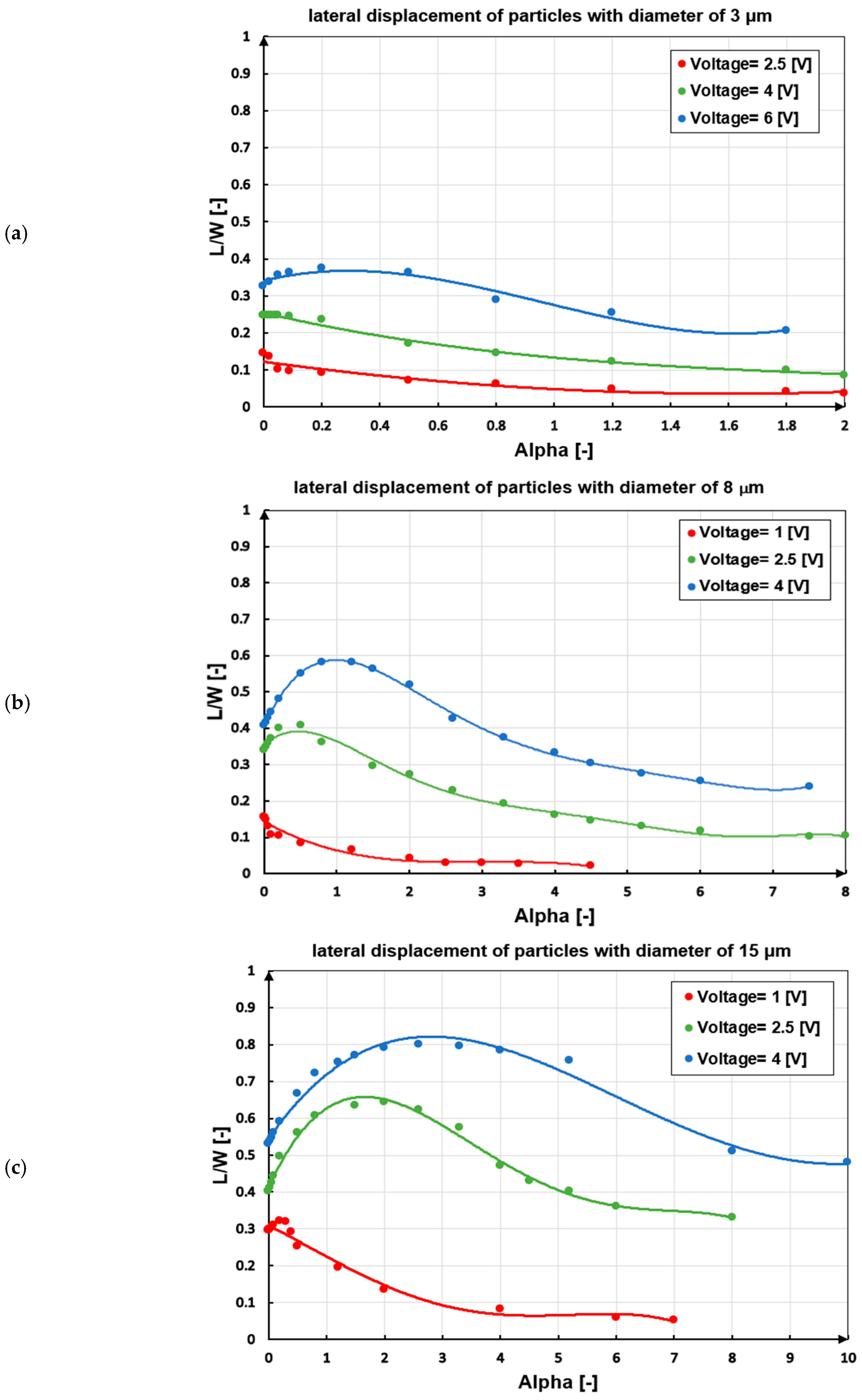
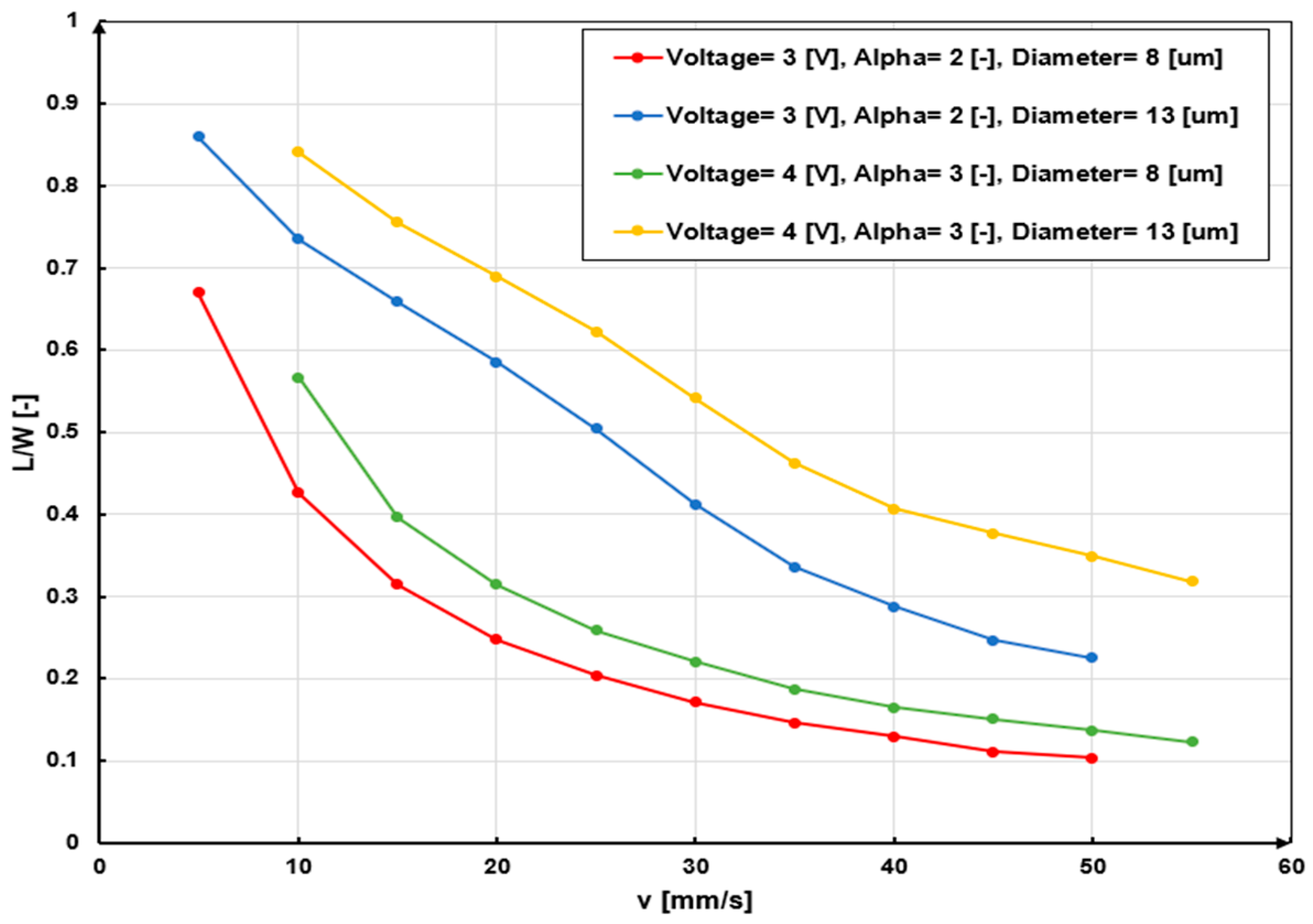
3.2.3. Voltage and Particle Size

As Figure 7 demonstrates, by increasing the particles’ diameter, their deflection overlaps. One of the downsides of such a system is that it cannot separate particles with similar diameters.

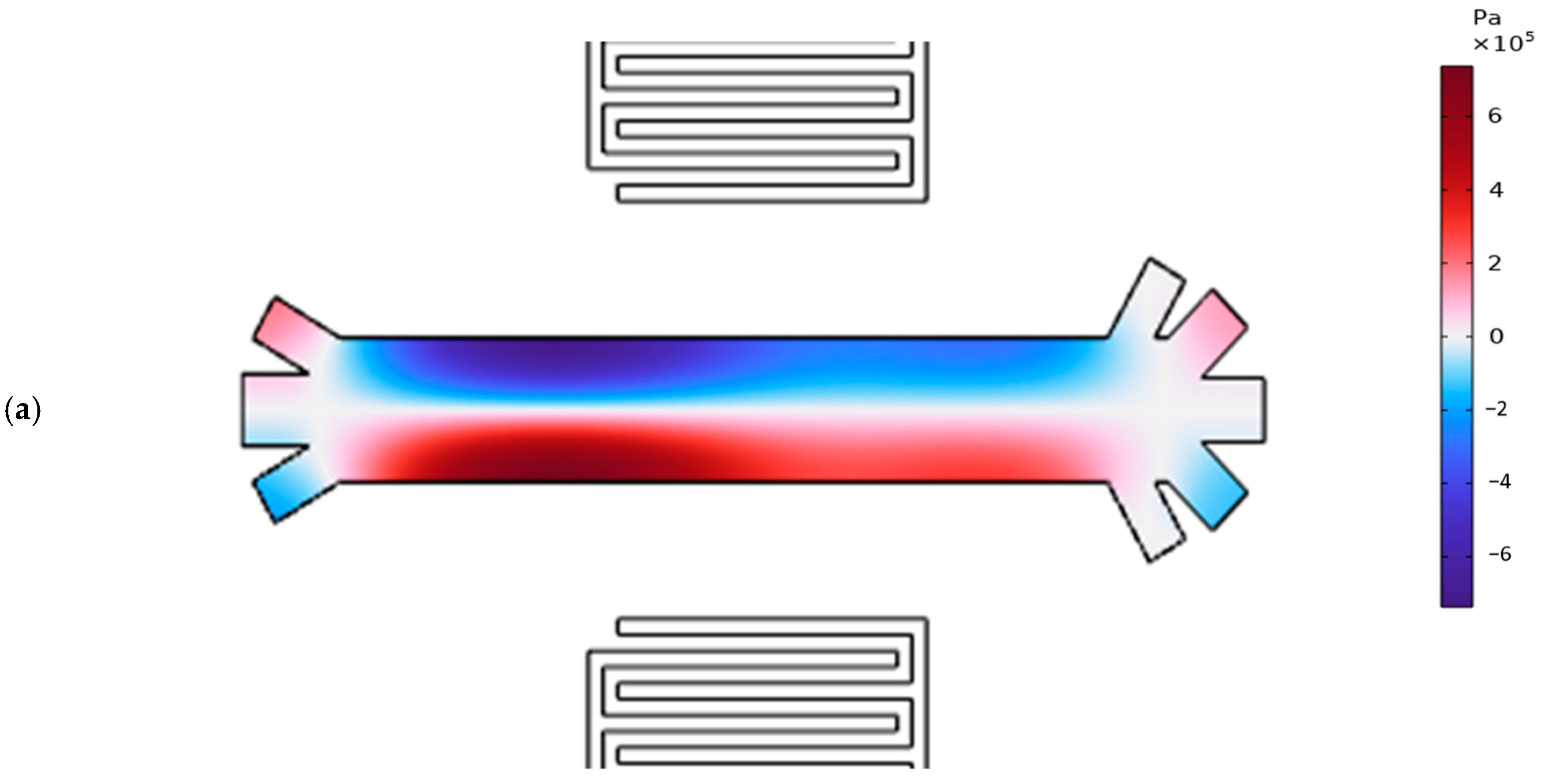
3.3. Pressure Acoustic and Particle Trajectory of the Proposed Model

After applying a voltage of 8.5 V and an RF of 8.28 MHz as the resonance frequency of the system, the acoustic pressure field is shown in Figure 8a. As the results show, PLTs, RBCs, and WBCs are separated successfully (Figure 8b).
As the microchannel’s shape is rectangular, the resonance frequency can be calculated using Equation (14) [53]:
f n x , n y , n z = C f 2 n x 2 l 2 + n y 2 w 2 + n z 2 h 2
The theoretical first resonance frequency, as suggested by Equation (14), is 8.227 MHz, and the simulation reports 8.28 MHz as the resonance frequency.

3.4. Guidelines for Designing SSAW-Based Blood Cell Separation Systems

In response to the need for practical design considerations, this section outlines guidelines for adapting the proposed SSAW-based model for blood cell applications. The recommendations include parameter selection, channel geometry optimization, and operational settings (Figure 9).

4. Conclusions

In this study, we propose a novel configuration for a SAW-based platform designed to simultaneously separate WBCs, RBCs, and PLTs in a single stage. This advancement builds on previous work by Shamloo et al. [50], offering an improvement with the development of a five-outlet channel capable of achieving multi-cell separation in a more efficient and streamlined process. The innovation lies in the optimization of key operational parameters, such as the inlet velocity ratio, resonance frequency, and applied voltage, which collectively enhances particle separation efficiency.
We developed and validated a numerical model to investigate the influence of these parameters on the performance of the system. Specifically, we investigated the effects of the inlet velocity ratio (buffer solution to blood sample), system operating speed, and applied voltage on particle deflection and acoustic radiation force (ARF). These factors were optimized to minimize overlapping deflection problems for particles of different sizes, thereby improving the overall separation process. An operating frequency of 8.28 MHz and an applied voltage of 8.5 V were identified as the key parameters for achieving effective separation.
While this model is idealized and largely theoretical, it represents a significant step forward in the design of more efficient acoustofluidic devices. Our study paves the way for future experimental validation and further refinement of the design. By integrating this method with other particle separation techniques, the system’s efficiency can be enhanced, potentially leading to the development of new devices for a wide range of biomedical applications.

Author Contributions

Conceptualization and methodology by M.H., M.T.G. and M.M.; modelling and validation by M.H. and M.T.G.; analysing the results and writing the manuscript by all authors. All authors have read and agreed to the published version of the manuscript.

Funding

This research received no external funding.

Data Availability Statement

Data is contained within the article.

Conflicts of Interest

The authors declare no conflict of interest.

Nomenclature

Letters and SymbolsDescription
Abbreviation
ARFAcoustic radiation force
BAWBulk acoustic wave
IDTInterdigital transducer
PANPressure anti-node
PLTPlatelet
PNPressure node
RBCRed blood cell
SAWSurface acoustic wave
SSAWStanding surface acoustic wave
TSAWTraveling surface acoustic wave
WBCWhite blood cell
Latin Letters
a Radius of particle, [ μ m ]  
c Speed of sound, [ m s ]
C Elasticity matrix of piezoelectric, [ G P a ]
D Electric displacement vector, [ C m 2 ]
E Electric field vector, [ V / m ]
f Frequency, [MHz]
e Piezoelectric stress matrix, [ C m 2 ]
h Height of the microchannel, [ μ m ]
l Length of the microchannel, [ μ m ]
L Lateral displacement of particles, [ μ m ]
m Mass of particles, [ K g ]
P Pressure, [ P a ]
r Radius of particles, [ μ m ]
U Time-averaged radiation force potential, [J]
u Velocity, [ m s ]
w Width of the microchannel, [ μ m ]
W Half of the width of the microchannel, [ μ m ]
n x ,   n y ,   n z Frequency mode in each direction, [-]
Greek Letters
αInlet velocity ratio (buffer/blood), [-]
ϵStrain tensor, [-]
εDielectric matrix, [-]
κCompressibility, [ P a 1 ]
μViscosity, [ P a . s ]
μ B Bulk viscosity, [ P a . s ]
ρ Density, [ K g m 3 ]
σMechanical stress tensor, [ P a ]
ϕContrast factor, [-]
ωAngular velocity, [ r a d s ]

References

  1. Zhou, J.; Mukherjee, P.; Gao, H.; Luan, Q.; Papautsky, I. Label-free microfluidic sorting of microparticles. APL Bioeng. 2019, 3, 041504. [Google Scholar] [CrossRef]
  2. Zhang, T.; Hong, Z.-Y.; Tang, S.-Y.; Li, W.; Inglis, D.W.; Hosokawa, Y.; Yalikun, Y.; Li, M. Focusing of sub-micrometer particles in microfluidic devices. Lab Chip 2020, 20, 35–53. [Google Scholar] [CrossRef]
  3. Augustsson, P.; Magnusson, C.; Nordin, M.; Lilja, H.; Laurell, T. Microfluidic, label-free enrichment of prostate cancer cells in blood based on acoustophoresis. Anal. Chem. 2012, 84, 7954–7962. [Google Scholar] [CrossRef] [PubMed]
  4. Wu, W.-T.; Martin, A.B.; Gandini, A.; Aubry, N.; Massoudi, M.; Antaki, J.F. Design of microfluidic channels for magnetic separation of malaria-infected red blood cells. Microfluid. Nanofluidics 2016, 20, 41. [Google Scholar] [CrossRef] [PubMed]
  5. Lee, S.H.; Cha, B.; Yi, H.G.; Kim, J.; Jeon, J.S.; Park, J. Acoustofluidic separation of bacteria from platelets using tilted-angle standing surface acoustic wave. Sens. Actuators B Chem. 2024, 417, 136161. [Google Scholar] [CrossRef]
  6. Wu, M.; Ouyang, Y.; Wang, Z.; Zhang, R.; Huang, P.-H.; Chen, C.; Li, H.; Li, P.; Quinn, D.; Dao, M.; et al. Isolation of exosomes from whole blood by integrating acoustics and microfluidics. Proc. Natl. Acad. Sci. USA 2017, 114, 10584–10589. [Google Scholar] [CrossRef] [PubMed]
  7. Karimi, S.; Mojaddam, M.; Majidi, S.; Mehrdel, P.; Farré-Lladós, J.; Casals-Terré, J. Numerical and experimental analysis of a high-throughput blood plasma separator for point-of-care applications. Anal. Bioanal. Chem. 2021, 413, 2867–2878. [Google Scholar] [CrossRef]
  8. Nepal, S.; Feng, H.; Gale, B.K. Optimization of a microfluidic spiral channel used to separate sperm from blood cells. Biomicrofluidics 2020, 14, 064103. [Google Scholar] [CrossRef]
  9. Sethu, P.; Sin, A.; Toner, M. Microfluidic diffusive filter for apheresis (leukapheresis). Lab Chip 2006, 6, 83–89. [Google Scholar] [CrossRef]
  10. Ghoshal, K.; Bhattacharyya, M. Overview of platelet physiology: Its hemostatic and nonhemostatic role in disease pathogenesis. Sci. World J. 2014, 2014, 781857. [Google Scholar] [CrossRef]
  11. Kuhn, V.; Diederich, L.; Iv, T.C.S.K.; Kramer, C.M.; Lückstädt, W.; Panknin, C.; Suvorava, T.; Isakson, B.E.; Kelm, M.; Cortese-Krott, M.M. Red blood cell function and dysfunction: Redox regulation, nitric oxide metabolism, anemia. Antioxid. Redox Signal. 2017, 26, 718–742. [Google Scholar] [CrossRef]
  12. Tigner, A.; Ibrahim, S.A.; Murray, I. Histology, White Blood Cell; StatPearls; StatPearls Publishing: Treasure Island, FL, USA, 2020. [Google Scholar]
  13. Cheng, X.; Irimia, D.; Dixon, M.; Sekine, K.; Demirci, U.; Zamir, L.; Tompkins, R.G.; Rodriguez, W.; Toner, M. A microfluidic device for practical label-free CD4+ T cell counting of HIV-infected subjects. Lab Chip 2007, 7, 170–178. [Google Scholar] [CrossRef] [PubMed]
  14. Sajeesh, P.; Sen, A.K. Particle separation and sorting in microfluidic devices: A review. Microfluid. Nanofluid. 2014, 17, 1–52. [Google Scholar] [CrossRef]
  15. Zhu, P.; Wang, L. Passive and active droplet generation with microfluidics: A review. Lab Chip 2017, 17, 34–75. [Google Scholar] [CrossRef]
  16. Fadaei, M.; Majidi, S.; Mojaddam, M. Droplet generation in a co-flowing microchannel influenced by magnetic fields applied in parallel and perpendicular to flow directions. J. Magn. Magn. Mater. 2023, 570, 170528. [Google Scholar] [CrossRef]
  17. Dittrich, P.S.; Manz, A. Lab-on-a-chip: Microfluidics in drug discovery. Nat. Rev. Drug Discov. 2006, 5, 210–218. [Google Scholar] [CrossRef] [PubMed]
  18. Jahromi, A.K.; Saadatmand, M.; Eghbal, M.; Yeganeh, L. Development of simple and efficient Lab-on-a-Disc platforms for automated chemical cell lysis. Sci. Rep. 2020, 10, 11039. [Google Scholar] [CrossRef]
  19. Leung, C.M.; de Haan, P.; Ronaldson-Bouchard, K.; Kim, G.-A.; Ko, J.; Rho, S.R.; Chen, S.; Duran, M.S.; Wan, J.M.M.M.; Pingguan-Murphy, S.V.V.; et al. A guide to the organ-on-a-Chinature. Rev. Methods Primers 2022, 2, 33. [Google Scholar] [CrossRef]
  20. Xuan, X.; Zhu, J.; Church, C. Particle focusing in microfluidic devices. Microfluid. Nanofluid. 2010, 9, 1–16. [Google Scholar] [CrossRef]
  21. Yiannacou, K.; Sariola, V. Controlled manipulation and active sorting of particles inside microfluidic chips using bulk acoustic waves and machine learning. Langmuir 2021, 37, 4192–4199. [Google Scholar] [CrossRef]
  22. Wong, S.H.; Ward, M.C.; Wharton, C.W. Micro T-mixer as a rapid mixing micromixer. Sens. Actuators B Chem. 2004, 100, 359–379. [Google Scholar] [CrossRef]
  23. Fan, R.; Wu, J.; Li, Y.; Zhang, C.; Hui, Z.; Zheng, A. Droplet-based microfluidics for drug delivery applications. Int. J. Pharm. 2024, 663, 124551. [Google Scholar] [CrossRef]
  24. Bayazidi, S.; Mojaddam, M.; Mohseni, A. Performance optimization of nozzle-diffuser piezoelectric micropump with multiple vibrating membranes by design of experiment (DOE) method. J. Appl. Fluid Mech. 2023, 16, 1356–1370. [Google Scholar]
  25. Doh, I.; Cho, Y.-H. A continuous cell separation chip using hydrodynamic dielectrophoresis (DEP) process. Sens. Actuators A Phys. 2005, 121, 59–65. [Google Scholar] [CrossRef]
  26. Çetin, B.; Li, D. Dielectrophoresis in microfluidics technology. Electrophoresis 2011, 32, 2410–2427. [Google Scholar] [CrossRef] [PubMed]
  27. Pamme, N.; Wilhelm, C. Continuous sorting of magnetic cells via on-chip free-flow magnetophoresis. Lab Chip 2006, 6, 974–980. [Google Scholar] [CrossRef] [PubMed]
  28. Alnaimat, F.; Dagher, S.; Mathew, B.; Hilal-Alnqbi, A.; Khashan, S. Microfluidics based magnetophoresis: A review. Chem. Rec. 2018, 18, 1596–1612. [Google Scholar] [CrossRef]
  29. Petersson, F.; Åberg, L.; Swärd-Nilsson, A.-M.; Laurell, T. Free flow acoustophoresis: Microfluidic-based mode of particle and cell separation. Anal. Chem. 2007, 79, 5117–5123. [Google Scholar] [CrossRef]
  30. Pamme, N. Continuous flow separations in microfluidic devices. Lab Chip 2007, 7, 1644–1659. [Google Scholar] [CrossRef]
  31. Wu, L.; Guan, G.; Hou, H.W.; Bhagat, A.A.S.; Han, J. Separation of leukocytes from blood using spiral channel with trapezoid cross-section. Anal. Chem. 2012, 84, 9324–9331. [Google Scholar] [CrossRef]
  32. Sun, J.; Liu, C.; Li, M.; Wang, J.; Xianyu, Y.; Hu, G.; Jiang, X. Size-based hydrodynamic rare tumor cell separation in curved microfluidic channels. Biomicrofluidics 2013, 7, 011802. [Google Scholar] [CrossRef] [PubMed]
  33. Rezaei, B.; Zand, M.M.; Javidi, R. Numerical simulation of critical particle size in asymmetrical deterministic lateral displacement. J. Chromatogr. A 2021, 1649, 462216. [Google Scholar] [CrossRef] [PubMed]
  34. McGrath, J.; Jimenez, M.; Bridle, H. Deterministic lateral displacement for particle separation: A review. Lab Chip 2014, 14, 4139–4158. [Google Scholar] [CrossRef] [PubMed]
  35. Noruzshamsian, O.; Mohseni, A.; Mojaddam, M. Design of a micro-separator for Circulating Tumor Cells (CTCs) from blood flow using hybrid pinched flow fractionation (PFF) and dielectrophoresis methods. J. Solid Fluid Mech. 2020, 10, 281–296. [Google Scholar]
  36. Tokeshi, M. Applications of Microfluidic Systems in Biology and Medicine; Springer: Singapore, 2019. [Google Scholar]
  37. Olofsson, K.; Hammarström, B.; Wiklund, M. Acoustic separation of living and dead cells using high density medium. Lab Chip 2020, 20, 1981–1990. [Google Scholar] [CrossRef] [PubMed]
  38. Wei, W.; Wang, Y.; Wang, Z.; Duan, X. Microscale acoustic streaming for biomedical and bioanalytical applications. TrAC Trends Anal. Chem. 2023, 160, 116958. [Google Scholar] [CrossRef]
  39. Rasouli, R.; Villegas, K.M.; Tabrizian, M. Acoustofluidics–changing paradigm in tissue engineering, therapeutics development, and biosensing. Lab Chip 2023, 23, 1300–1338. [Google Scholar] [CrossRef]
  40. Li, W.; Zhang, J.; Chen, H.; Liu, X. Acoustofluidic precise manipulation: Recent advances in applications for micro/nano bioparticles. Adv. Colloid Interface Sci. 2024, 332, 103276. [Google Scholar] [CrossRef]
  41. Dykes, J.; Lenshof, A.; Åstrand-Grundström, I.; Laurell, T.; Scheding, S. Efficient removal of platelets from peripheral blood progenitor cell products using a novel micro-chip based acoustophoretic platform. PLoS ONE 2011, 6, e23074. [Google Scholar] [CrossRef]
  42. Chen, Y.; Wu, M.; Ren, L.; Liu, J.; Whitley, P.H.; Wang, L.; Huang, T.J. High-throughput acoustic separation of platelets from whole blood. Lab Chip 2016, 16, 3466–3472. [Google Scholar] [CrossRef] [PubMed]
  43. Shi, J.; Huang, H.; Stratton, Z.; Huang, Y.; Huang, T.J. Continuous particle separation in a microfluidic channel via standing surface acoustic waves (SSAW). Lab Chip 2009, 9, 3354–3359. [Google Scholar] [CrossRef]
  44. Folch, A. Introduction to bioMEMS; CRC Press: Boca Raton, FL, USA, 2016. [Google Scholar]
  45. Wu, M.; Ozcelik, A.; Rufo, J.; Wang, Z.; Fang, R.; Huang, T.J. Acoustofluidic separation of cells and particles. Microsyst. Nanoeng. 2019, 5, 32. [Google Scholar] [CrossRef] [PubMed]
  46. Taatizadeh, E.; Dalili, A.; Rellstab-Sánchez, P.; Tahmooressi, H.; Ravishankara, A.; Tasnim, N.; Najjaran, H.; Li, I.T.S.; Hoorfar, M. Micron-sized particle separation with standing surface acoustic wave—Experimental and numerical approaches. Ultrason. Sonochemistry 2021, 76, 105651. [Google Scholar] [CrossRef] [PubMed]
  47. Li, P.; Mao, Z.; Peng, Z.; Zhou, L.; Chen, Y.; Huang, P.-H.; Truica, C.I.; Drabick, J.J.; El-Deiry, W.S.; Dao, M.; et al. Acoustic separation of circulating tumor cells. Proc. Natl. Acad. Sci. USA 2015, 112, 4970–4975. [Google Scholar] [CrossRef] [PubMed]
  48. Şahin, M.A.; Çetin, B.; Özer, M.B. Investigation of effect of design and operating parameters on acoustophoretic particle separation via 3D device-level simulations. Microfluid. Nanofluid. 2020, 24, 8. [Google Scholar] [CrossRef]
  49. Lei, J.; Cheng, F.; Li, K.; Guo, Z. Numerical simulation of continuous separation of microparticles in two-stage acousto-microfluidic systems. Appl. Math. Model. 2020, 83, 342–356. [Google Scholar] [CrossRef]
  50. Shamloo, A.; Boodaghi, M. Design and simulation of a microfluidic device for acoustic cell separation. Ultrasonics 2018, 84, 234–243. [Google Scholar] [CrossRef] [PubMed]
  51. González, I.; Earl, J.; Fernández, L.J.; Sainz, B.; Pinto, A.; Monge, R.; Alcalá, S.; Castillejo, A.; Soto, J.L.; Carrato, A. A label free disposable device for rapid isolation of rare tumor cells from blood by ultrasounds. Micromachines 2018, 9, 129. [Google Scholar] [CrossRef]
  52. Destgeer, G.; Lee, K.H.; Jung, J.H.; Alazzam, A.; Sung, H.J. Continuous separation of particles in a PDMS microfluidic channel via travelling surface acoustic waves (TSAW). Lab Chip 2013, 13, 4210–4216. [Google Scholar] [CrossRef]
  53. Bruus, H. Theoretical Microfluidics; Oxford University Press: Oxford, UK, 2007. [Google Scholar]
  54. Gupta, S.; Bit, A. Acoustophoresis-based biomedical device applications. In Bioelectronics and Medical Devices; Elsevier: Amsterdam, The Netherlands, 2019; pp. 123–144. [Google Scholar]
  55. Ni, Z.; Yin, C.; Xu, G.; Xie, L.; Huang, J.; Liu, S.; Tu, J.; Guo, X.; Zhang, D. Modelling of SAW-PDMS acoustofluidics: Physical fields and particle motions influenced by different descriptions of the PDMS domain. Lab Chip 2019, 19, 2728–2740. [Google Scholar] [CrossRef]
Figure 1. A schematic representation of an acoustofluidic microchip based on a piezoelectric substrate (1) utilizing IDTs (2) to separate blood cells suspended in the flow. The traveling acoustic waves generated by the IDTs form pressure nodes (PNs) and anti-nodes (PANs) across the microchannel (3) (shown by the red waves). The blood cells are attracted by either PNs or PANs and isolated through the outlets.
Computation 13 00042 g001
Figure 2. (a) Two-dimensional schematic representation of the microfluidic device, including the IDTs on the sides of the microchannel to generate traveling surface acoustic waves. The microchannel has three inlets to inject the buffer solution and the blood samples and five outlets to isolate the separated blood cells by acoustic waves (all dimensions are in µm); (b) 3D schematic of the setup and the designated inlet/outlets.
Computation 13 00042 g002
Figure 3. Results validated by a former study [50]. (a) Pressure acoustic profile at a resonance frequency of 7.453 MHz, (b) pressure magnitude at a voltage of 3 V, (c) pressure magnitude at a voltage of 5 V, (d) WBC isolation through the middle outlet, and (e) PLT isolation via the side outlets.
Computation 13 00042 g003
Figure 4. The dimensionless lateral displacement versus velocity ratio for particles with (a) 3 µm, (b) 8 µm, and (c) 15 µm diameters.
Computation 13 00042 g004
Figure 5. Comparison of particle deflection at V = 3 V with different α   v a l u e s : (a) velocity field at α = 0 , (b) particle deflection at α = 0 ,   (c) velocity field at α = 0.6 , and (d) particle deflection at α = 0.6 .
Computation 13 00042 g005
Figure 6. Lateral displacement of particles versus velocity of the system.
Computation 13 00042 g006
Figure 7. Dimensionless lateral displacement of particles ranging from 2 to 20 µm versus voltage.
Computation 13 00042 g007
Figure 8. Results of the new system’s design: (a) pressure acoustic field; (b) separation and capturing of particles in the specific reservoir.
Computation 13 00042 g008aComputation 13 00042 g008b
Figure 9. The flowchart indicates the process and setting required to separate blood cells using the proposed SSAW-based microchip.
Computation 13 00042 g009
Table 1. Microchannel characteristics.
SpecificationValueMaterial
Pitch of IDT40 µmAluminum
Width of IDT10
Number of fingers of IDT5
Length of IDT200 µm
Piezoelectric substrate1500 µm × 750 µmLiNb O 3
Microchannel522 µm × 90 µmWater
Rotation of side inlets of microchannel 30 °
Rotation of outer outlets of microchannel 60 °
Rotation of middle outlets of microchannel.45 °
Table 2. Material properties [55].
MaterialPropertiesValue
WaterDensity998 kg/m 3998 k g / m 3
Sound speed1481 m/s
Bulk viscosity2.47 m P a . s
AluminumModulus of elasticity70 G P a
Density2700 k g / m 3
Piezoelectric substrateDensity4700 k g / m 3
Disclaimer/Publisher’s Note: The statements, opinions and data contained in all publications are solely those of the individual author(s) and contributor(s) and not of MDPI and/or the editor(s). MDPI and/or the editor(s) disclaim responsibility for any injury to people or property resulting from any ideas, methods, instructions or products referred to in the content.

