1. Introduction
With the rapid advancement of synthetic aperture radar (SAR) imaging and AI technologies, the accuracy of radar target detection and recognition has significantly improved [
1,
2], posing new challenges for the development of radar stealth and jamming strategies. Traditional stealth and camouflage coatings are constrained by the limitations of their material systems and exhibit slow progress. Additionally, active radar jamming devices are costly, difficult to deploy, and unable to respond instantaneously to electromagnetic waves. As a result, there is an urgent need to develop novel camouflage strategies for radar imaging. Dihedral angle structures are a major source of strong scattering in SAR radar imaging due to their unique multi-angle reflection properties, and the prominent scattering points they generate in radar images are key indicators for radar recognition. Thus, effectively altering the scattering characteristics of dihedral angle structures is a critical prerequisite for achieving stealth and camouflage in jamming radar systems. According to electromagnetic far-field theory, the far field represents the spatial Fourier transform of the radiation source. Consequently, the target’s scattering characteristics can be described as the spatial Fourier transform of the induced electric and magnetic currents generated by the target [
3,
4,
5,
6,
7,
8,
9,
10]. Altering the induced currents on the target’s surface can substantially affect its echo characteristics [
11,
12,
13,
14,
15,
16].
Recently, significant advances have been made in SAR-based target recognition and scattering manipulation, which are highly relevant to stealth and camouflage design. For example, Existing research [
17] introduces a multi-azimuth scattering feature fusion network that leverages multi-view scattering information to substantially improve SAR target recognition accuracy. Similarly, the oriented SAR ship detection framework [
18], which combines edge deformable convolution with point set representation, achieves superior detection performance for low-RCS targets in complex maritime environments. These studies highlight the growing importance of advanced SAR perception and scattering feature exploitation, providing essential context for developing new stealth strategies.
Diffuse scattering coding metasurfaces are a novel type of electromagnetic stealth material recently proposed. The coding units of these metasurfaces redirect incident electromagnetic fields in space by modifying the surface-induced currents, causing the incident electromagnetic waves to scatter in a dispersed and chaotic manner [
19,
20,
21,
22,
23]. This disperses the Poynting vector of the electromagnetic waves, reducing echoes in specific directions and achieving stealth [
24,
25,
26,
27]. Based on their scattering effect on electromagnetic waves, coding metasurfaces can effectively alter the propagation of electromagnetic waves and thus have the potential to modify scattering properties. Achieving this function requires careful design of their spectral response to electromagnetic waves. Current research on diffuse scattering coding metasurfaces mainly focuses on the design and optimization of coding units [
28,
29,
30,
31], with limited studies on their application in stealth and camouflage for specific structures, particularly regarding modifications in scattering characteristics.
Beyond canonical corner-scatterers and diffuse-coding concepts, platform-level integration under monostatic look and manufacturability are decisive for practical stealth, especially for airborne platforms operating in transonic–supersonic regimes. In such environments, radome assemblies, skin panelization, conformal curvature, thermal excursions, rain/particle erosion, and maintenance constraints jointly bound thickness, areal density, feature sizes, and stack layups. A pragmatic route that has seen broad acceptance in flight hardware is to embed patterned sheets within radome-style, frequency-selective surface (FSS) stacks, trading spectral selectivity, angular response, and structural integrity. Recent engineering studies on manufacturable radomes for monostatic RCS reduction systematically discuss these trade-offs and process windows and provide actionable guidelines for airworthy implementation [
32].
In line with these practices, our SDES is realized as a thin, conformal resistive-pattern laminate compatible with FSS layups, thereby bridging laboratory-level metasurface design to platform-ready installations while retaining the deterministic dispersion needed to suppress grazing-incidence returns. Meanwhile, we develop a wideband super-dispersion encoded surface (SDES) tailored to right-angle dihedral corners that delivers deterministic, angle-stable dispersion together with controlled loss so as to suppress corner-dominated coherent returns. Unlike diffuse or random coding approaches, the proposed SDES prescribes a sequence that preserves dispersion effectiveness over 12–18 GHz and across broad angular sectors, directly addressing the band- and angle-fragility observed in prior designs. We further connect field-level scattering control to imaging-domain observables by employing perceptual-hashing and SSIM-based similarity metrics, thus closing the gap between RCS reduction claims and verifiable changes in radar images. On canonical dihedral and dihedral–cylindrical hybrids, a thin, conformal hardware implementation removes corner hot spots and achieves a 9.6 dB reduction in average monostatic RCS while driving the image-similarity index down to 0.31, filling the lack of broadband, conformal, and experimentally validated demonstrations on these baseline geometries. Finally, we summarize practical design rules that map target dispersion profiles and angle ranges to coding sequences and layer parameters, providing a transferable recipe for extending the method to other canonical scatterers and bands.
2. Demonstration of Scattering Property Change Mechanism
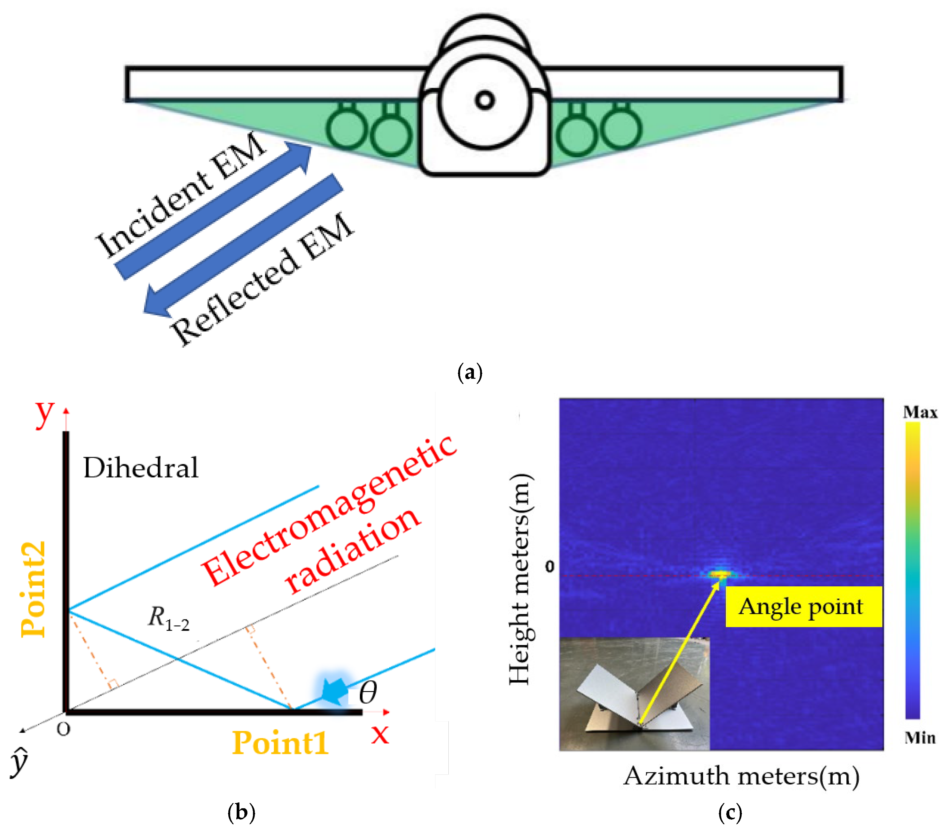
To connect the proposed method with a realistic platform before descending to canonical geometry, we start from the wing–fuselage junction and the under-wing store region where a dihedral cavity is naturally formed (see
Figure 1a). In a monostatic look with low grazing elevation, incident rays impinge on the inner faces of this cavity, undergo double-bounce interactions, and re-radiate coherently back toward the radar. The two specular bounces align the optical paths, while edge-induced currents at the corner further concentrate the return; as a result, the wing-root dihedral governs both the RCS peak and the image hot spots under grazing views. Right-angle dihedral angle structures are among the most common radar target structures, and they generate strong responses in monostatic radar systems.
Figure 1b illustrates the right-angle dihedral angle structure. Using the geometric optics method, we establish the
axis as the straight line passing through the origin and parallel to the radar incident wave. This axis is equivalent to the xoy coordinate system rotated counterclockwise by
degrees, where
represents the angle of incidence. Assuming point 1’s coordinates are (x, 0), the radar wave is relayed to point 2 (0, y), and then reflected back to the radar at the same angle
, in accordance with the law of specular reflection.
To determine the distance traveled by the echo, we calculate the
coordinates of points 1 and 2 in the radar irradiation coordinate system. Points sharing the same
coordinate in the radar distance direction can be considered as one point. Specifically, for point 1,
, and for point 2,
. The distance traveled by the electromagnetic wave from point 1 to point 2 is defined as
. Consequently, for a single-base radar, the phase difference generated from transmission to reception of the echo can be expressed as:
Equation reveals that all distance-oriented information acquired by the radar becomes compressed to the corner point (0, 0) of the entire two-sided angular structure, resulting in a very strong echo signal at this point. Experimental results, as depicted in
Figure 1c, confirm the consistency between the measured 2D distance-azimuth direction imaging outcomes and the theoretically derived results.
Based on the aforementioned analysis, the critical factor in mitigating strong scattering at the corner point of a two-sided angle is the introduction of a phase difference between the transmitter and receiver to decompress the distance azimuthal direction. Consequently, the design’s success hinges on achieving sufficient dispersion of the incident electromagnetic wave. It is extremely difficult to eliminate strong scattering points at dihedral corners using conventional radar-absorbing coatings, because such coatings can only suppress the amplitude of reflected waves. According to the aforementioned mechanism, after the accumulation of multiple frequency components, corner points still act as strong scattering sources. Therefore, there is an urgent engineering need for new approaches capable of completely eliminating strong scattering at corner points. Recently developed techniques, such as the “invisible door” [
33], provide feasible solutions for fully suppressing strong scattering at corners. The invisible door concept relies on engineering the local phase and amplitude of reflected waves to redirect or diffuse incident electromagnetic waves, rendering the corner region effectively “invisible” to radar. By combining this approach with SDES, individual unit cells can be strategically arranged to achieve broadband and angle-adaptive dispersion of scattered energy, thereby eliminating strong scattering points at geometric singularities while maintaining overall energy attenuation.
3. Construction of SDES
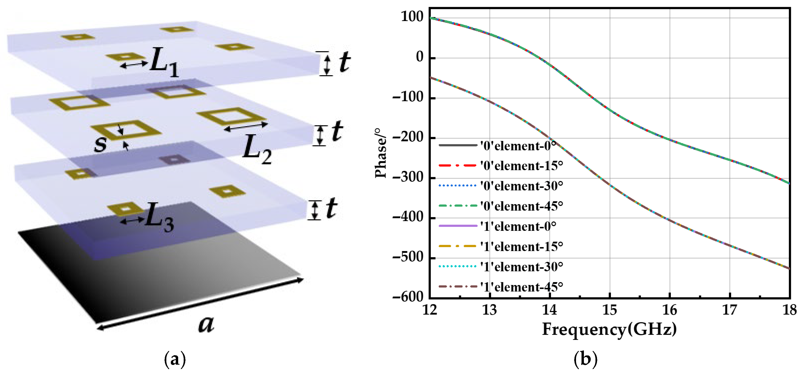
It is the key to construct an electromagnetic metasurface with uniform dispersion of electromagnetic waves in the wide band range, which is called a wideband super-dispersion encoded surface (SDES). The SDES cell structure is shown in
Figure 2a, constructed using a 1-bit coding scheme (0 and 1 cells). Each unit consists of three dielectric layers and two layers of conductive patterned surfaces, with dimensions of a = 12.5 mm for the unit size, t = 2 mm for dielectric thickness, and s = 2 mm for the ring pattern width. To control the slope distribution of the reflection phase curves, the dimensions of the metallic square rings (
L1,
L2,
L3) within each unit cell were systematically varied. Using CST Microwave Studio, we calculated the reflection phase responses of different unit cells and established a database mapping each unit cell geometry to its corresponding phase curve. Since each structural parameter has 13 discrete values, a total of 2197 unit configurations were simulated. From this database, two unit cells with approximately linear phase responses, similar phase slopes, and an average phase difference of 180° were selected to form the SDES, where the two units are labeled as ‘0’ and ‘1’. Inspired by the dispersion-controlled metasurface, it is easy to use particle swarm optimization (PSO) algorithm to find two metasurface elements in the constructed database that are insensitive to incident in the broadband range. For optimizing the encoding matrix
, where each element x
m,n = 0 or 1 corresponds to selecting one of two metasurface unit cells. These two units are chosen because they exhibit nearly linear phase responses with an approximate 180° phase difference over the frequency range of interest, which ensures stable and efficient scattering control.
The fitness criterion for optimizing the coding sequence is defined as:
where
F =
GHz is the frequency range,
represents the maximum scattered power at frequency
f,
measures the scattering uniformity in the angular domain, where
the power within the
k-th angular sector and
is its mean value,
α and
β are weighting coefficients, typically set to
α = 1 and
β = 1. By minimizing
, the optimization achieves peak scattering suppression and uniform angular diffusion over a wide frequency range. For particle
p at iteration
t, the velocity and position are updated as:
where
is the velocity of the i-th dimension for particle
p;
is the binary position;
c1 = 2.0 and
c2 = 2.0 are cognitive and social learning factors;
r1,
r2 are random numbers;
= 0.5 is the threshold for binary decision. The inertia weight
ω is linearly decreased from
ωmax = 0.8,
ωmin = 0.7 during iterations to balance exploration and exploitation. The optimization process stops if either the global best fitness improvement is less than
ε = 10
−3 over 10 iterations, or the maximum number of iterations,
Tmax = 50, is reached.
Specifically, unit #2 was selected as the ‘0’ cell, with ring dimensions
L1 = 3.0 mm,
L2 = 9.0 mm, and
L3 = 3.5 mm. Unit #256 was selected as the ‘1’ cell, with ring dimensions
L1 = 3.0 mm,
L2 = 5.5 mm, and
L3 = 3.0 mm. The simulated phase dispersion curves of the two selected unit cells are shown in
Figure 2b. As observed, the two units exhibit nearly parallel slopes, with average phase differences of 180.3°, 180.5°, 180.6°, and 180.7° under incident angles of 0°, 15°, 30°, and 45°, respectively. These deviations from the ideal 180° phase difference are only 0.3°, 0.5°, 0.6°, and 0.7°, demonstrating that the selected units provide stable broadband phase compensation suitable for binary coding metasurface design.
The SCES is designed with a diffuse scattering array composed of selected super-dispersive cells. The array consists of the two types of units described earlier, and their cascading order determines the overall configuration of the metasurface. Previous studies on coding metasurfaces for scattering reduction often used small unit groups (2 × 2 or 3 × 3) as a bit, which effectively mitigates phase shifts and scattering suppression due to excessively small cells. However, this approach limits the variety of coding combinations for a given array size. While energy attenuation in the specular direction remains unaffected by the unit group size, the scattering becomes more concentrated. By using individual units as bits, we can achieve sufficient beam dispersion, and increasing the number of cells further enhances scattering beam dispersion. Our coding array is composed of 24 × 24 super-dispersive unit cells, with each cell acting as a bit, and the overall metasurface size is 300 × 300 mm. Based on this array configuration, the coding sequence of ‘0/1’ cells is optimized using the simulated annealing (SA) algorithm to improve the dispersion of the bistatic scattering pattern. The scattering pattern is influenced by the coding sequence, cell size, and frequency. A frequency-domain optimization term is introduced to the design process of the random coding sequence. The aggregation of directional functions at various frequencies serves as the fitness criterion for the optimization algorithm, enabling comprehensive broadband optimization. In the ideal case, the maximum directivity at each frequency point is minimized. The optimization process follows these steps: first, the algorithm determines the optimal coding sequence for each frequency point (12, 13, … 18 GHz). Then, the fitness of the obtained coding sequence at each frequency is calculated. Finally, by aggregating the fitness values and subtracting the cumulative value, the coding sequence with the lowest target function value is selected as the optimal solution. The fitness function is defined as:
where
signifies the maximum directivity function generated by metasurface at each frequency point,
denotes the maximum value of the directivity function generated by the optimal coding pattern at each frequency point, and
represents the difference between
and
. Since the
obtained by the simulated annealing algorithm is fixed for each frequency, this reference value can, in principle, be chosen arbitrarily. The minimal
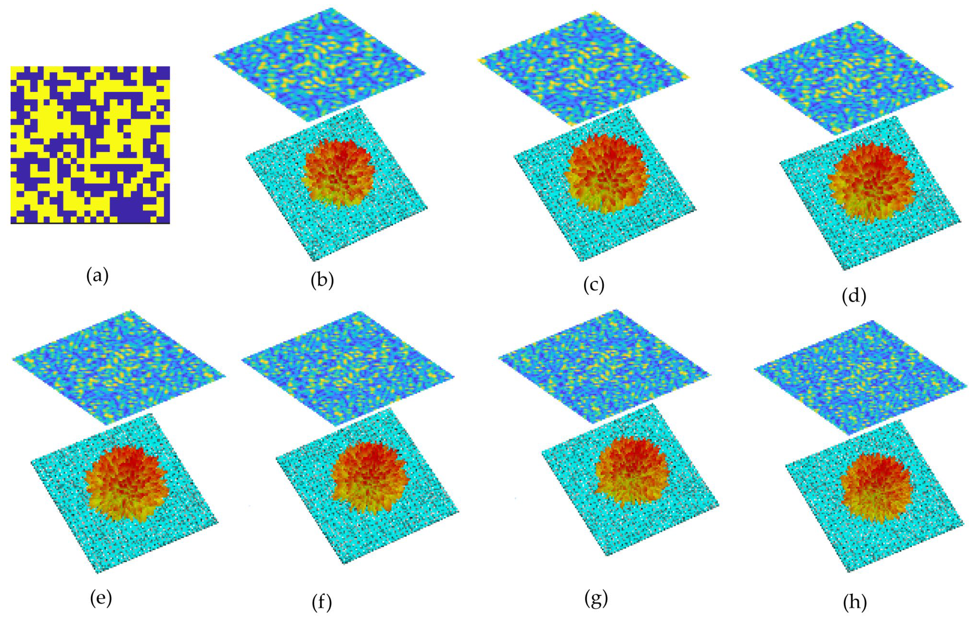
F value corresponding coding sequence is selected as the optimization result. The optimized SDES cell arrangement is shown in
Figure 3a. And the bistatic scattering pattern could be calculated by this formula:
Here, the metasurface is composed of an N × N array of equal-sized lattices with dimension d. Each lattice hosts a binary sub-array labeled “0” or “1”, whose distribution can be arbitrarily designed. Here, is the element factor (unit-cell pattern). A is the planar array factor, d denotes the lattice period, and denotes the scattering phase assigned to the ()-th lattice, taking binary values {0, π}; m and n denote the indices of the metasurface unit cells in the coding sequence; k is the wave number associated with each frequency fi, defined as , where is the wavelength corresponding to frequency ; θ and φ are the elevation and azimuth angles of an arbitrary observation direction.
The designed SDES was constructed in CST software 2022, and full-wave simulations were performed. The calculated reflection patterns in the 12–18 GHz range are shown in
Figure 3b–h. It can be observed that the reflected electromagnetic wave energy is evenly dispersed in all directions at each frequency point, with no dominant lobe formation.
The SDES in this work provides a promising solution for range-direction decompression by redirecting electromagnetic energy in space. By covering the dihedral corner surfaces with the broadband coding metasurface, the incident waves are effectively diffused and reoriented, generating phase differences at different points on the corner surfaces, which can potentially eliminate strong scattering at corner points. Moreover, the introduction of cylindrical structures further reduces the strong scattering from the dihedral corners. According to optical refraction principles, the cylindrical geometry naturally scatters electromagnetic waves uniformly in multiple directions, which aligns with the core concept of this work. Finally, the inclusion of the cylinders introduces an effective pivot point for range-direction camouflage within the overall structure. While eliminating strong corner scattering, this approach shifts the scattering center of the entire dihedral structure, thereby achieving effective range-direction concealment.
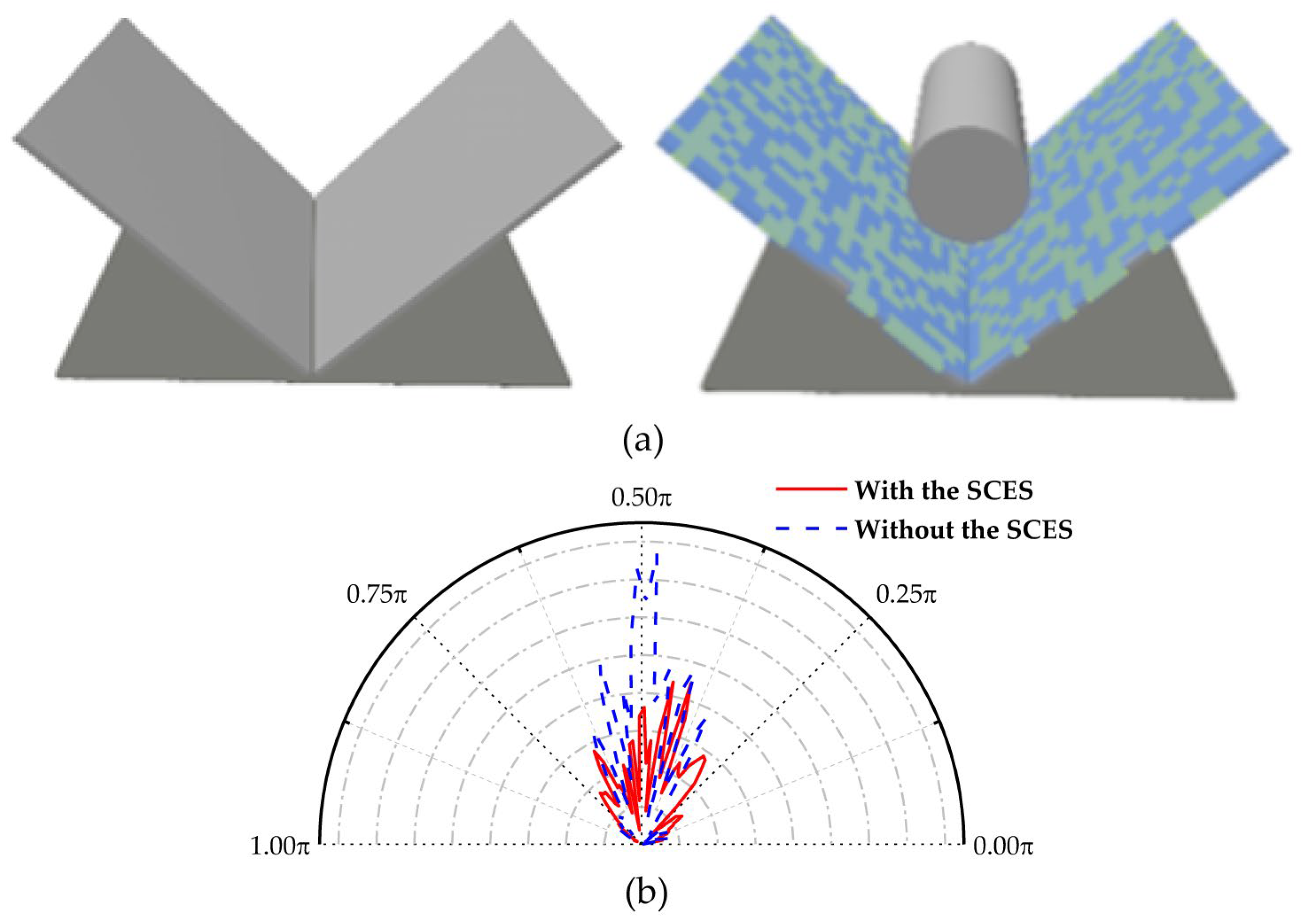
To validate that the introduction of the SDES and cylindrical structures can eliminate strong scattering points at the corner, full-wave far-field simulations were conducted using CST software 2022 for both configurations.
Figure 4a shows the two comparison models, and the comparison results are presented in
Figure 4b. The results indicate that, without the SDES and cylindrical structures, the main lobe disappears, and the peak scattering is reduced by 52%. This demonstrates that the electromagnetic waves can be effectively diffused through their scattering effects, generating phase differences. Therefore, this method effectively eliminates the strong scattering points caused by the dihedral corner effect.
4. Experimental Validation for the Effect of the Scattering Property Changes by SDES
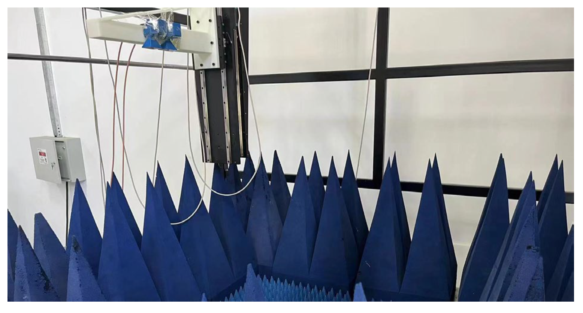
Next, the stealth camouflage strategy of the dihedral corner structure was experimentally validated using radar imaging, with the experimental setup shown in
Figure 5. The distance between the radar and the sample was 1 m, and 121 sampling points were used along both the x and y directions. The number of sampling points was determined based on the Nyquist sampling theorem, considering the distance from the radar to the sample. The phase variations obtained from simulation and experiment were incorporated into the phase matrix of the back-projection (BP) imaging algorithm to generate time delays of the echo phases, ultimately producing the radar image.
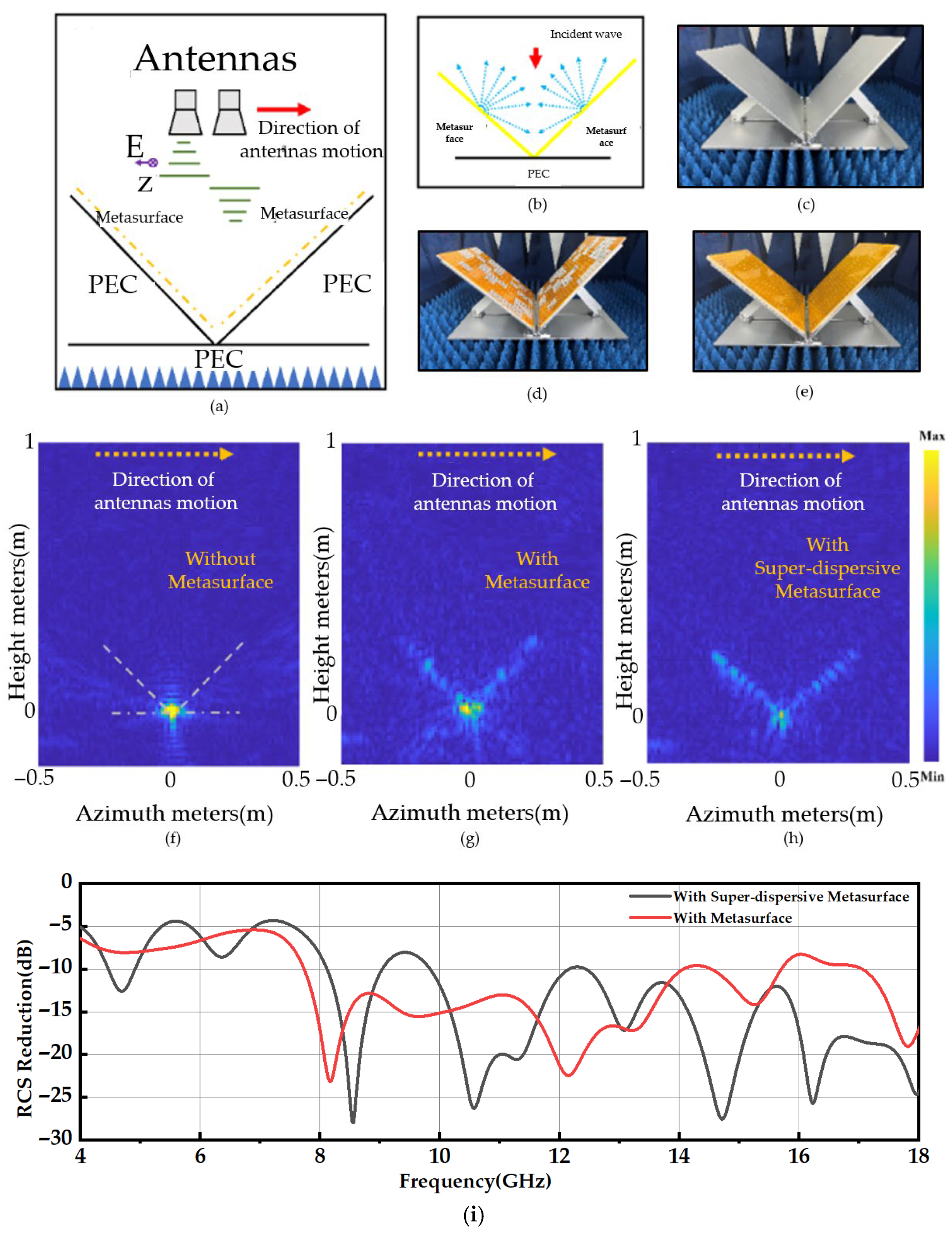
The experimental configuration is presented in
Figure 6a, where the single-site antenna is swept horizontally at 4 mm intervals around the dihedral angle structure. This is performed at a vertical distance of 1 m. The measurement frequency range spans 12–18 GHz. Radar imaging is performed using the BP algorithm, focusing exclusively on the polarization direction. To visually convey the concept of eliminating strong scattering points through SDES deployment,
Figure 6b illustrates the arrangement of the SDES. The underlying idea hinges on capitalizing on the SDES’s ability to sufficiently disperse electromagnetic waves, thereby introducing a non-zero phase difference in the optical path traversed by the emitted and received electromagnetic waves. This effect facilitates the dispersion of electromagnetic waves upwards over distance.
In fabricating the SDES samples, we utilized a Polyimide (PI) film with a thickness of 0.075 mm. This film was coated with ultra-low resistance silver paste through printing technology. Subsequently, the coated film was affixed to the customized dielectric foam, resulting in the creation of the SDES. This cost-effective approach yields samples with a shorter preparation timeline compared to conventional PCB circuit boards. For comparative purposes, we also prepared randomly coded metasurface using the same technique [
31]. Subsequent experimentation encompassed radar distance azimuthal imaging of various configurations, including the dihedral corner metal structure, the dihedral corner structure with conventional metasurfaces, and the dihedral corner structure equipped with SDES. The corresponding experimental setups are depicted in
Figure 6c–e, while the resultant imaging outcomes are displayed in
Figure 6f–h. In the visualization, the horizontal coordinates correspond to the azimuthal direction, while the vertical coordinates denote the distance direction. The color scale portrays the magnitude of scattering intensity emanating from the scattering source. In
Figure 6f, in accordance with the theoretical derivation, the radar image of the dihedral corner structure exhibits distance-direction compression, positioning a scattering intensity point at the corner coordinates (0, 0). Upon applying a conventional metasurface at the corner of the dihedral corner (depicted in
Figure 6g), the distance direction begins to decompress and disperse due to the metasurface’s scattering impact on electromagnetic waves. However, the dispersion on the corner surface lacks uniformity due to non-uniform scattering at various frequency points. Additionally, the coding pair formed by subarrays tends to concentrate in the angle of electromagnetic dispersion, preserving the existence of strong scattering points at the corner coordinates.
By introducing a SDES cell to the corner surface (depicted in
Figure 6h), uniform dispersion of the distance direction is achieved across the dihedral angle’s corner surface. This uniform dispersion arises from the broad frequency-dependent dispersion characteristics of the SDES cell. Notably, the strong scattering point at the corner location is notably attenuated, confirming the efficacy of our designed SDES in achieving substantial dispersion across a wide frequency range. This outcome underscores the feasibility of the concept illustrated in
Figure 6b. Nevertheless, the outcome in
Figure 6h does not align with our initial expectation, as the strong scattering source at the corner point persists, albeit weakened. Meanwhile, the reflection coefficients of both configurations were compared across the 4–18 GHz frequency range, as shown in
Figure 6i. It was found that in the 4–14 GHz band, the mean scattering decreased by only 0.4 dB after introducing the SDES cell, whereas in the 14–18 GHz band, the mean scattering was reduced by 7.5 dB. Notably, in the 12–14 GHz range, no significant reduction was observed, indicating that the strong scattering source at the corner still persists.
To achieve complete elimination of the strong scattering point at the dihedral corner, we introduced a cylindrical structure to enhance scattering control. From an application perspective, this introduction is both necessary and justified. Notably, in many platforms, dihedral angle structures are integrated with metal cylindrical components, such as aircraft mounting areas, vehicle hubs, and similar structures. Therefore, investigating the combined effect of dihedral and cylindrical structures on the overall scattering characteristics, particularly with the incorporation of the SDES, is of significant practical and theoretical importance.
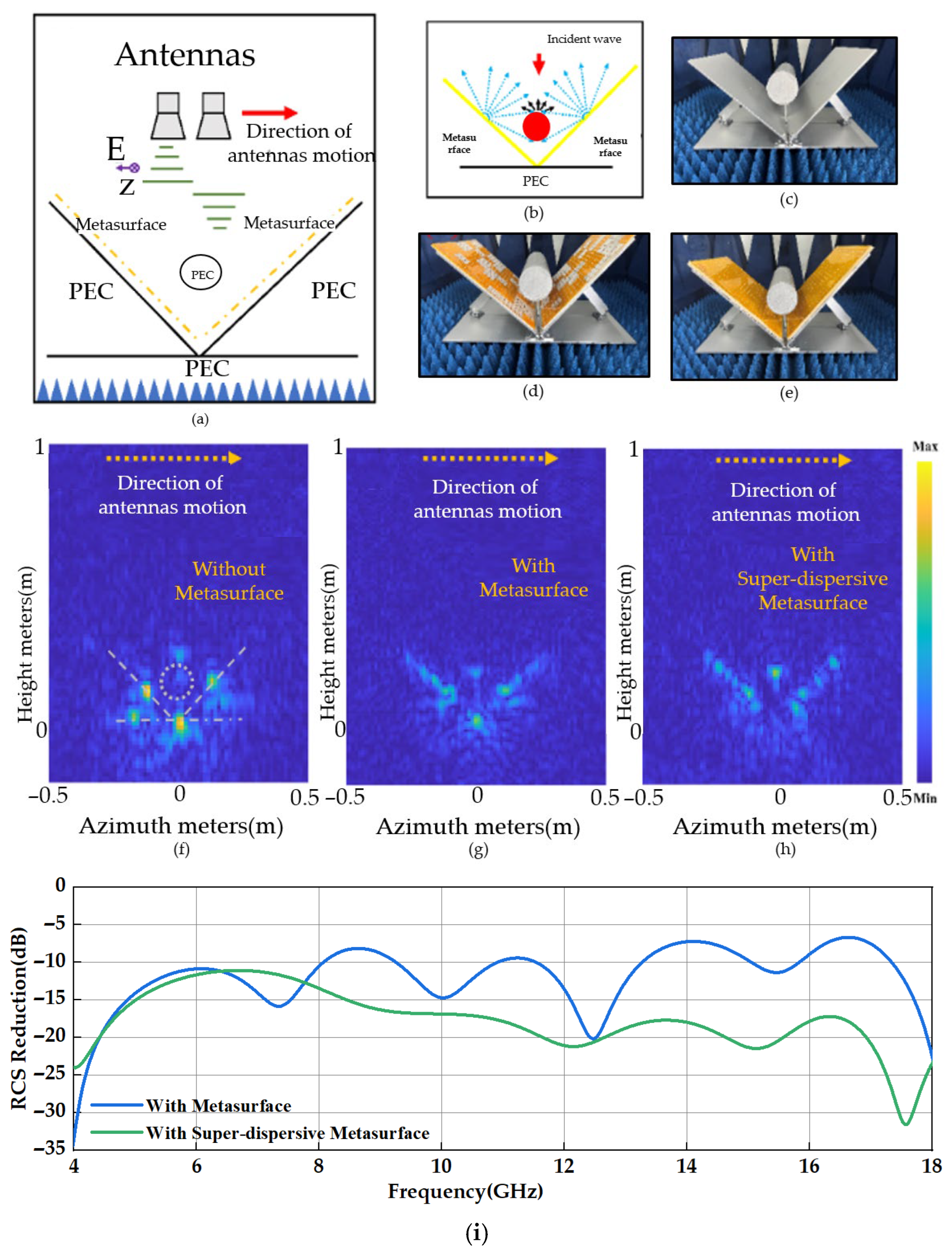
The experimental configuration is illustrated in
Figure 7a. The crucial role of incorporating metal cylinders in attaining scattering point suppression and enabling distance-directed camouflage is underscored. Firstly, due to its small electrical dimensions, the cylindrical structure can obstruct a portion of directly and vertically incident electromagnetic waves at the corner point, averting pronounced echoes. Secondly, the inherent scattering impact of the cylindrical structure on electromagnetic waves can disperse a portion of the originally compressed waves toward the corner surface. With the SDES positioned on the corner surface, echoes emitted from the SDES can be directed towards the cylindrical surface, thereby engendering multiple scattering occurrences, as depicted in
Figure 7b. Crucially, given that electromagnetic waves do not deviate from their course, elimination of the strong scattering point at the corner alters the scattering property of the dihedral angular structure. This comprehensive transformation in radar target attributes is further facilitated by the cylindrical structure, serving as a pivotal point for distance-directed camouflage in the upward direction.
Similarly to the experiments in
Figure 6, we conducted radar azimuthal distance imaging on the dihedral angular structure enhanced with metal cylinders, the cylindrical dihedral angular structure with conventional metasurfaces, and the electromagnetic attenuation region. The test configuration illustrations are presented in
Figure 7c–e, while the resultant imaging outcomes are showcased in
Figure 7f,g.
Upon introducing the cylinder to the metal dihedral corner (
Figure 7f), the initial strong scattering point at the corner (
Figure 6f) divides into three points: the corner point and the centers of the two corner surfaces. In contrast, the cylinder’s scattering energy is relatively minor and comparable to the energy from points near the strong scattering point on the corner faces. Employing a randomly metasurfaces on the corner surfaces (
Figure 7g) leads to a noticeable weakening of the strong scattering point intensities at the corner points and surfaces, accompanied by partial distance direction compression on the corner surfaces. However, the scattering points at the corner points persist. Notably, by employing SDESs capable of uniformly scattering electromagnetic waves on the corner surface (
Figure 7h), we observe the complete vanishing of the strong scattering point at the corner. This results in uniform dispersion of the distance direction across the corner surface, with no pronounced scattering points. Scattering intensifies at the metal cylinder’s location. The strong scattering points at the corners were effectively eliminated by introducing structures within the corners and dihedral corners. Meanwhile, reflection measurements over the 4–18 GHz frequency range were conducted to compare the effect of SDES unit introduction (
Figure 7i). The results indicate that, in the 4–12 GHz band, the mean scattering is reduced by 2.9 dB, whereas in the 12–18 GHz band, the mean scattering is reduced by 9.6 dB. Notably, within the 12–18 GHz range, the scattering reduction remains lower than that of the metasurface alone, confirming that the strong scattering sources are effectively eliminated.
Notably, the corners themselves were left unaltered throughout this process. This technique resembles the “invisible door” approach, wherein a region of metamaterials manages electromagnetic wave responses in areas outside its physical boundary. Our study reaffirms the feasibility of this invisible door concept, providing a promising platform for the future design of illusion devices.
Concurrently, our proposed strategy demonstrates high effectiveness in achieving radar camouflage. In radar image recognition, the electromagnetic scattering from a target can be approximated as the summation of echoes from a series of independent, dominant scattering structures, termed scattering properties. These properties originate from the geometric characteristics of the target, and their distribution patterns closely correspond to radar image features. Therefore, the spatial arrangement of these scattering properties is a critical factor in radar-based target identification, and modifying these scattering properties is essential for successful camouflage.
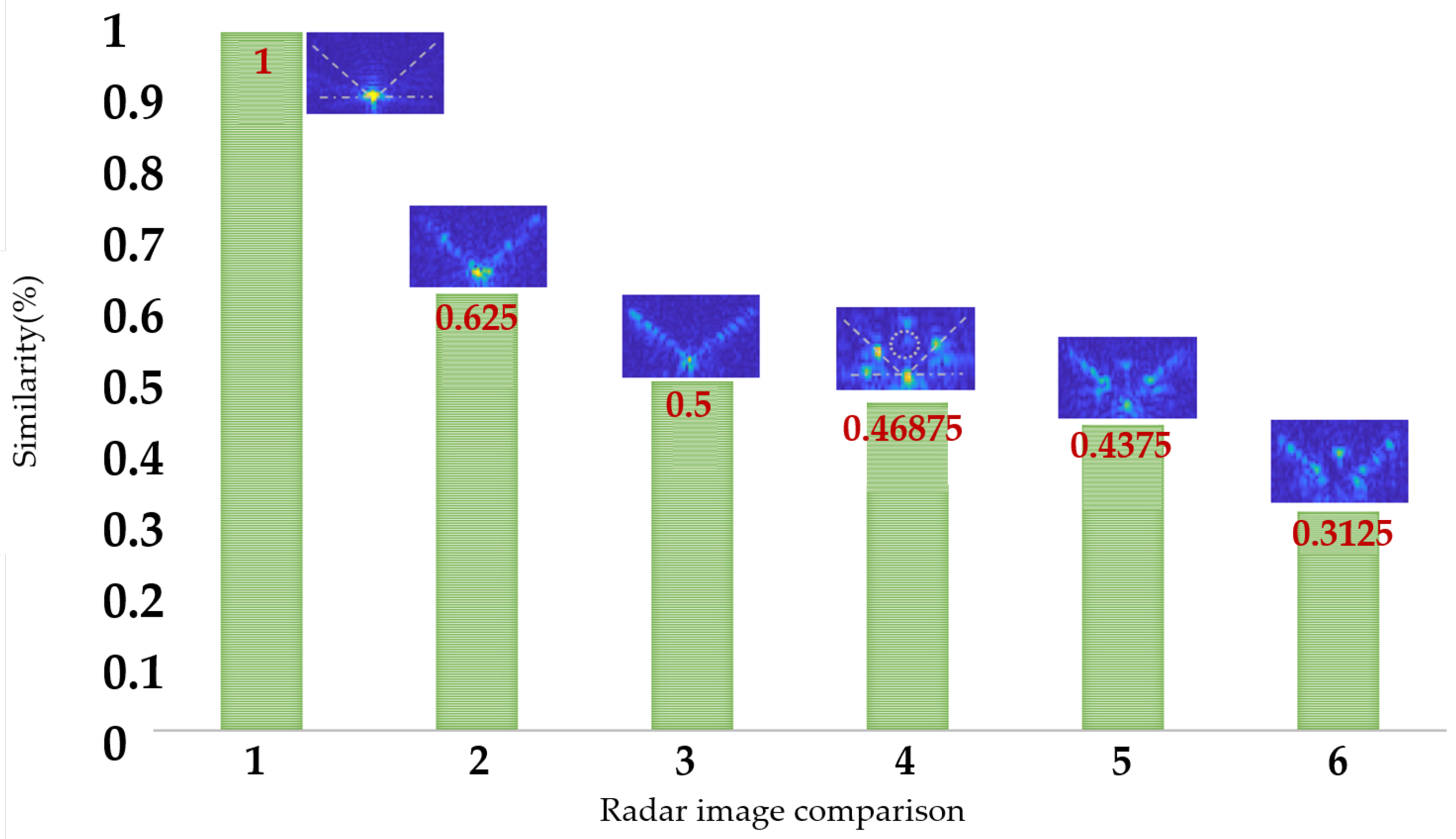
Finally, we employed the Perceptual Hashing (pHash) algorithm [
34], which is well-suited for radar image processing, to detect the similarity between two images. Unlike traditional hashing algorithms, perceptual hashing focuses on capturing the visual features of an image rather than just comparing the file contents at the byte level. By comparing the hash values of two images, the Hamming distance (i.e., the number of differing bits between two hash values) can be used to measure their similarity. This similarity can be further converted into a score ranging from 0 (completely different) to 1 (identical). According to data provided by the Swedish company Barracuda, a similarity score less than 0.7 indicates a major difference.
