Article

Investigation on the Flow and Heat Transfer Behavior of Molten Steel During Continuous Casting

1
Science and Technology Department, Jiujiang Polytechnic University of Science and Technology, Jiujiang 332020, China
2
Marine Engineering College, Dalian Maritime University, Dalian 116026, China
3
Offshore Oil Engineering Co., Ltd., Tianjin 300461, China
4
School of Automotive and Mechanical Engineering, Liaoning Institute of Science and Engineering, Jinzhou 121013, China
*
Author to whom correspondence should be addressed.
Computation 2025, 13(11), 257; https://doi.org/10.3390/computation13110257
Submission received: 12 September 2025 / Revised: 22 October 2025 / Accepted: 26 October 2025 / Published: 2 November 2025
(This article belongs to the Special Issue Advances in Computational Methods for Fluid Flow)

Abstract

The flow and heat transfer inside the mold play an important role in the quality of the casting billet during continuous casting. In this work, a three-dimensional coupled model of flow and heat transfer was established, and the flow field and temperature distribution characteristics of molten steel were explored in depth. The results indicated that the narrow impact position is 315 mm away from the meniscus. The maximum turbulence kinetic energy of the centerline reached 0.00284 m2∙s−2, 108 mm from the narrow surface. The temperature of the steel liquid on the path of the two splitting strands located in the upper and lower circulation zones was above 1781 K. The temperature range from the center of the billet to the narrow 1/4 section, which was enclosed by the upper annular flow zone and 400 mm below the liquid level, was relatively low and lower than the liquidus temperature. The model can provide guidance for improving and optimizing the quality of continuous casting billets.

1. Introduction

In the steel manufacturing process, continuous casting is a vital production stage. During this operation, molten steel at elevated temperatures flows from the tundish into the mold via a submerged entry nozzle, where the copper mold walls rapidly cool the metal to form a preliminary solidified surface layer. The protective slag inside the mold lubricates and improves the heat transfer of the casting billet. During the mold’s oscillating motion, the solidifying shell gradually thickens and progresses into the secondary cooling zone, where complete solidification of the billet’s cross-section is achieved. The flow patterns of molten steel and heat transfer mechanisms within the mold critically determine the final billet quality. However, the extreme temperatures inside the continuous casting mold pose significant challenges for experimental measurements, resulting in a limited understanding of the steel’s flow and thermal behaviors. Since heat transfer and fluid dynamics are inherently interdependent, a coupled analysis of thermal–flow interactions in molten steel becomes essential for comprehensive investigation. [1,2,3,4,5].
Numerous researchers have investigated fluid flow and heat transfer phenomena within continuous casting molds [6,7,8,9]. A multiphase numerical model based on the Euler–Euler approach was developed by Narayan software. [10] to investigate hydrodynamic and thermodynamic interactions during quenching. The continuous and dispersed phases were simulated alongside plate motion using a sliding mesh method, enabling comprehensive analysis of single-jet quenching on a moving substrate. Yang et al. [11] developed a 3D/2D mixed columnar-equiaxed solidification model using the Eulerian–Eulerian approach, integrating macroscale heat transfer and fluid flow with microscale grain nucleation and growth. This comprehensive model effectively predicted grain sedimentation, solidification structure evolution, and macrosegregation in continuously cast round blooms under both mold electromagnetic stirring (M-EMS) and final electromagnetic stirring (F-EMS) conditions. Lu et al. [12] developed an integrated computational model to simulate the complete thin slab casting process for hot stamping steel. The model incorporated coupled fluid flow, heat transfer, and solidification phenomena. Their analysis determined the optimal process parameters at a casting speed of 4.0 m/min and superheat of 40 °C, achieving balanced flow characteristics, thermal profiles, and equiaxed crystal formation. Xie et al. [13] systematically investigated fluid flow patterns, thermal transport, and inclusion dynamics in a 700 mm round bloom mold equipped with a novel swirling flow SEN. Their results demonstrated that the innovative tundish-based swirling flow generator design effectively eliminated the detrimental impinging flow phenomenon typically associated with conventional single-port SEN systems. Li et al. [14] constructed a 0.5-scale Perspex mold model to investigate flow characteristics in ultra-wide slab casting. Through ink tracer visualization and contact measurement techniques, they examined how casting speed influences flow patterns and surface velocity. The study revealed dynamic flow transitions in the mold cavity, where nozzle jet momentum dissipated through wide-face impingement, reducing kinetic energy and altering subsequent flow dispersion. Zhang et al. [15] conducted a comparative study on inclusion behavior during complete solidification using both novel electromagnetic swirling flow in the nozzle (EMSFN) and conventional mold electromagnetic stirring (M-EMS). Quantitative analysis revealed that EMSFN reduced inclusion density by 23.9% and distribution fluctuations by 57.3% compared to M-EMS. These improvements were attributed to EMSFN’s shallower jet penetration depth and enhanced central flow uniformity. Wang et al. [16] developed a comprehensive 3D numerical model incorporating steel solidification, heat transfer, interfacial tension effects, multiphase flow dynamics, and mold oscillation. The model enabled detailed investigation of transient steel flow patterns, slag infiltration behavior at the meniscus, and initial shell formation during ultra-low bending bloom continuous casting, revealing their complex interdependencies.
While numerous studies have examined mold flow fields, the coupled interaction between fluid flow and heat transfer remains insufficiently understood. To address this knowledge gap, the present study develops a three-dimensional nozzle model to elucidate the interdependent flow–thermal characteristics in the mold. The established model provides theoretical foundations for enhancing continuous casting billet quality through process optimization.

2. Model Description

2.1. Model

The calculation object is the slab casting machine of a domestic steel plant. Half of the casting billet is selected as the calculation area, and the solid model and grid division of the casting billet are shown in Figure 1.
In this study, ANSYS Fluent 2024 software was used to perform numerical simulations, and the mathematical model was converted into a computable numerical model through the following steps: For geometric modeling and mesh discretization, a geometric model was first constructed based on the actual physical domain of molten steel flow. Subsequently, the computational domain was discretized using a structured mesh, and the global equations were converted into local equations on each control volume via the mesh. Fluent discretized the listed conservation equations using the finite volume method: the continuity equation, momentum equation, energy equation, and turbulence equation were integrated over each control volume, Gauss’s theorem was applied to convert volume integrals into surface integrals, and finally, a system of discrete algebraic equations was obtained. Then, the physical boundaries were converted into numerical constraints recognizable by the software, and various parameters of the model were substituted into the system. Additionally, the numerical calculations in this study were based on mature numerical methods in Fluent, including spatial discretization schemes, temporal discretization schemes, pressure-velocity coupling algorithms, and turbulence model discretization.

2.2. Assumption

Based on the Navier–Stokes momentum equation and the turbulent low-Reynolds-number k-ε equation, considering the conservation of energy and the influence of steel solidification and paste zone on the flow process, a three-dimensional mathematical model is established to describe the flow and heat transfer of steel in the mold. The following assumptions are as follows:
(1)
The liquid steel is an incompressible Newtonian fluid, so the influence of mold vibration is ignored.
(2)
The calculation boundary is a non-slip boundary, where the velocity, turbulent kinetic energy, and turbulent energy dissipation rate are all zero.
(3)
The influence of the phase transition is neglected.
(4)
The solidification shrinkage of the billet and the natural convection caused by density changes are ignored. The rapid outflow of molten steel from the nozzle impinges on the molten steel in the mold, causing forced convection; however, the density change of molten steel is very small, and the natural convection caused by the density change is far smaller than the forced convection caused by the impact of molten steel, so it can be ignored. The displacement caused by the contraction of the casting slab is very small, and its disturbance to the flow is negligible.

2.3. Governing Equation

(1)
Mass-conservation equation:
( ρ v i ) x i = 0
where ρ is the density of molten steel. vi is the velocity in the i direction. xi is the coordinate in the i direction.
(2)
Momentum conservation equation:
ρ v i t + ρ v j v i x j = p x i + x j [ μ e f f ( v i x j + v j x i ) ] + ρ g + S m
μ e f f = μ l + μ t
where vj is the velocity in the j direction. xj is the coordinate in the j direction; j corresponds to the thickness direction of the casting billet. p is the steel liquid pressure, g is the acceleration of gravity. μeff, μl and μt are the effective viscosity, physical viscosity, and turbulent viscosity of the molten steel. Sm is the pressure loss of the porous medium in the paste zone, and the calculation formula is as follows:
S m = 1 f l 2 f l 3 + ξ A m u s h v v c
where v is the velocity of the molten steel. vc is the pulling speed. fl is the volume fraction of the liquid phase in the paste zone. To avoid having a denominator of 0, ξ is set to a sufficiently small number. Amush is a constant in the paste zone.
(3)
Energy equation:
( ρ E ) t + ( ρ v i E + v i p ) x i = x i ( k e f f T x i )
E = h p ρ + v i 2 2
where T is the absolute temperature. keff is the effective thermal conductivity. h is the apparent enthalpy.
(4)
Turbulence control equation:
The Standard kε Dual equation model is as follows:
( ρ v j k ) x j = x j ( μ t σ k k x j ) + G k ρ ε + S k
( ρ v j ε ) x j = x j ( μ t σ ε ε x j ) + C 1 G k ε k C 2 ρ ε 2 k + S ε
where k is the turbulent pulsation kinetic energy. ε is the dissipation rate of turbulent pulsation kinetic energy. Constants C1, C2, σk and σε are constants. Gk represents the turbulent flow energy generation term. Sk and Sε are the source terms added to the equation.
S k = 1 f l 2 f l 3 + ξ A m u s h k
S ε = 1 f l 2 f l 3 + ξ A m u s h ε

2.4. Boundary Condition

The boundary conditions are given by:
(1)
The nozzle inlet is defined as the velocity inlet.
(2)
The computational domain exit is defined as the speed exit, while the speed is equal to the casting speed.
(3)
The mold liquid level is set as the free liquid level, and the shear force is null.
(4)
Both the mold wall and nozzle wall are treated as non-slip solid walls, while the flow field near the wall is treated as a standard wall function. The temperature boundary condition of the nozzle wall is treated as adiabatic. The mold wall is calculated using the second type of heat transfer boundary condition, and the heat flow is applied to the surface of the billet in the mold using a profile file.
The calculated parameters are listed in Table 1.

3. Results and Discussion

3.1. Narrow Impact Point

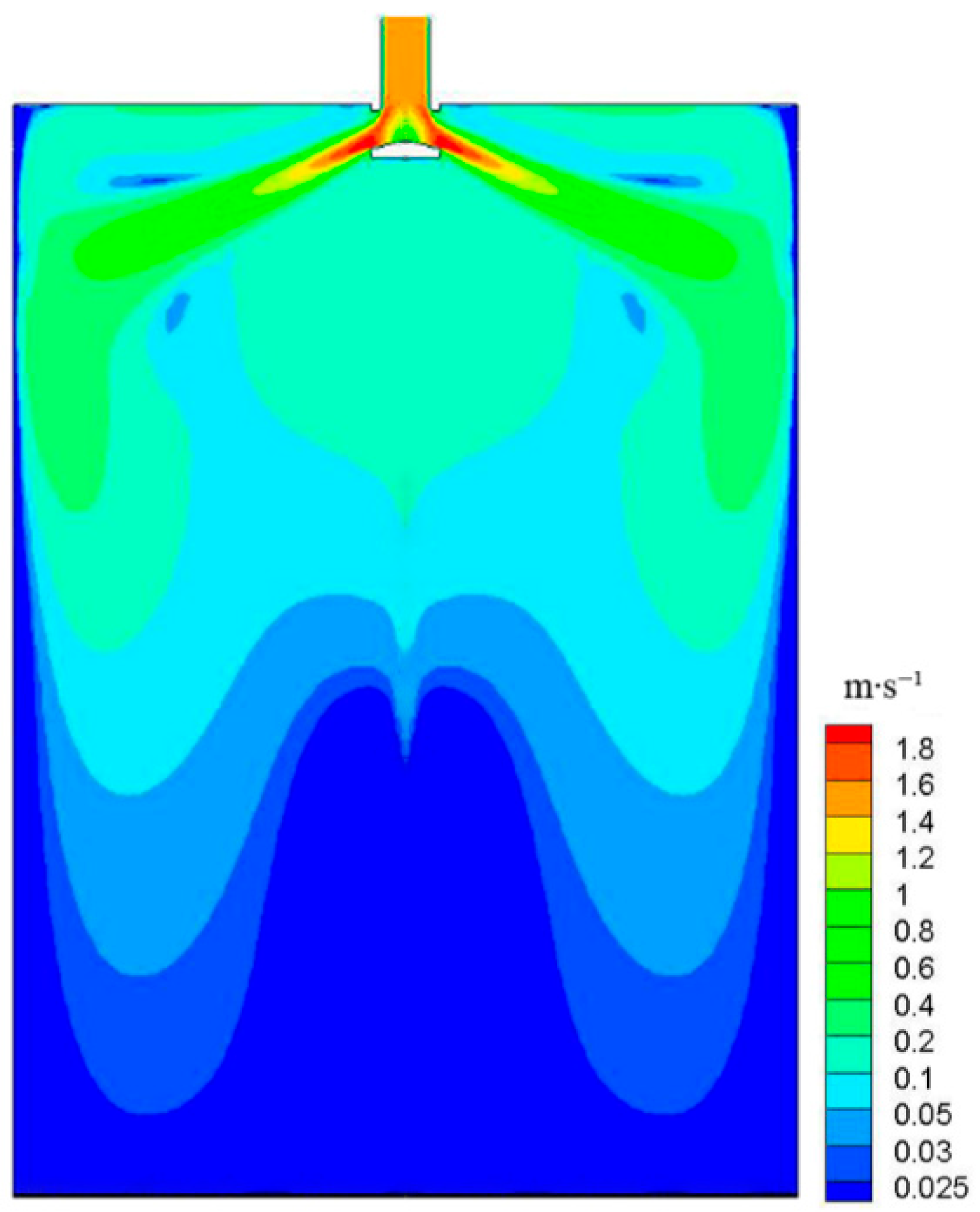
Figure 2 shows the temperature contours of molten steel in the mold. It can be seen that the narrow impact position is 315 mm away from the meniscus. By consulting information and considering parameters such as cross-sectional size and casting speed, it can be considered that the impact depth is relatively reasonable. The shallower the impact depth, the more sufficient nucleation and growth time there is for the initial solidified shell to remelt, which can refine the grain size of the billet and improve its density. The deeper the impact depth, the weaker the ability of inclusions to float up, and it is easy to cause thinning or even steel leakage of the solidified shell. Therefore, when the fluctuation of the mold liquid level can be controlled within a certain range, it is better to have a shallower impact depth of the current flow. Figure 3 is the flow contours of molten steel in the mould. It can be seen that the molten steel flows out of the submerged nozzle at a certain angle and enters the mould in the form of an impact stream, and then impacts the narrow surface. The tendency and order of magnitude of the results are in agreement with the results simulated by Takatani et al. and Li et al. [17,18]; they also agree with the experimental results proposed by Shamsi et al. and Lu et al. [19,20].

3.2. Turbulent Kinetic Energy

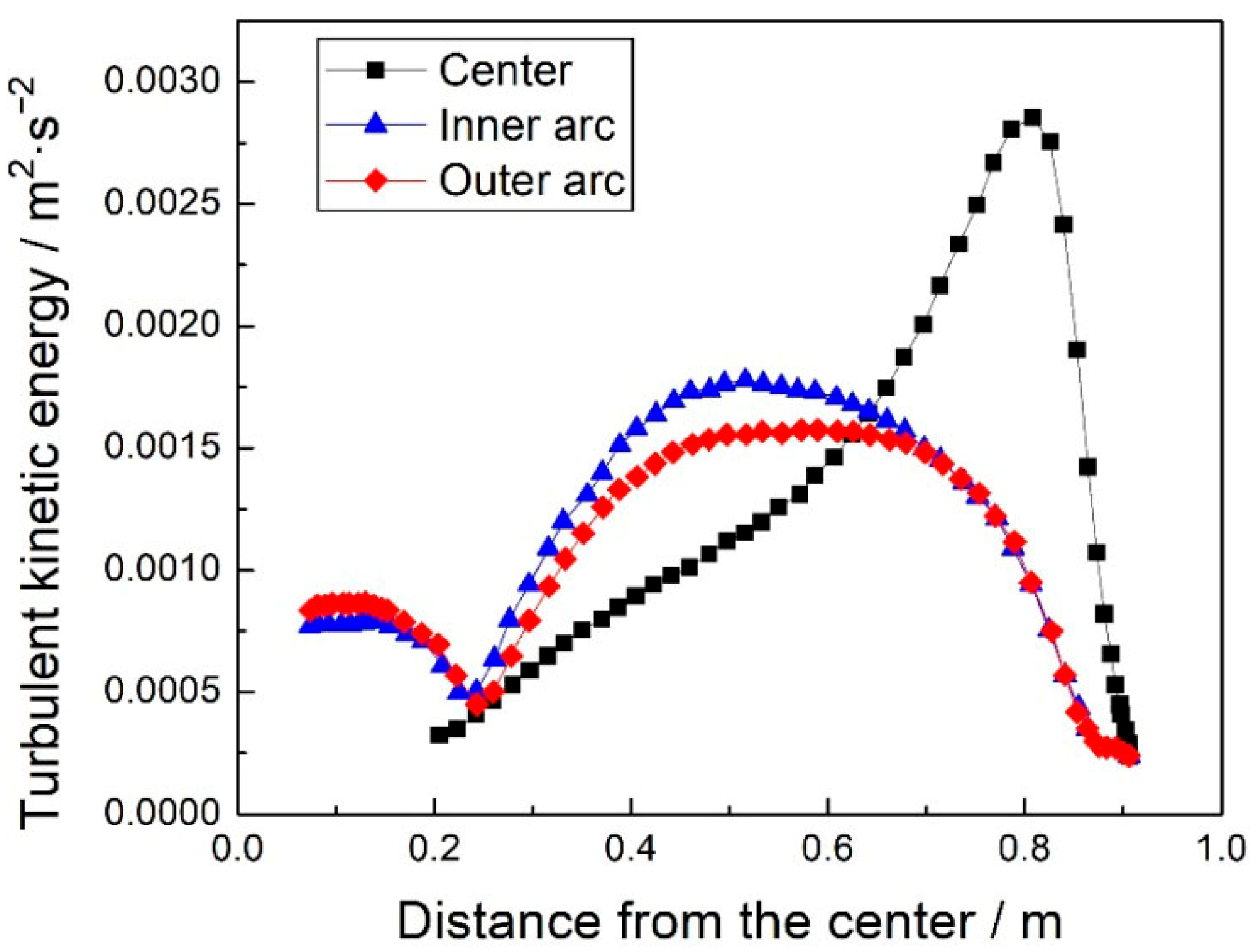
The variation in turbulent kinetic energy near the center of the free liquid surface and the two wide surfaces is shown in Figure 4. When the steel liquid reaches the meniscus in the upper annular flow zone, the velocity component perpendicular to the liquid surface direction reaches a local extreme value, and the horizontal flow velocity parallel to the liquid surface direction is also high, resulting in the highest turbulence kinetic energy of 0.00284 m2∙s−2 at the centerline, 108 mm from the narrow surface. According to the correspondence between turbulence kinetic energy and liquid surface wave height, the peak value of liquid surface wave height is also near this position, consistent with the results in Figure 2. Under the intense cooling effect of the copper plate, the viscosity of the steel liquid in the boundary area of the inner and outer arcs of the mold rapidly increases with the decrease in temperature. At the same time, due to the blocking effect of the initial shell and paste zone on the flow, the flow rate and kinetic energy gradually decrease. The maximum turbulent kinetic energy values near the inner and outer arcs are significantly lower than the centerline. At 1/4 width of the billet, the turbulent kinetic energy of the molten steel near the mold wall reaches its highest value, with the maximum values of the turbulent kinetic energy of the inner and outer arcs being 0.00166 m2∙s−2 and 0.00144 m2∙s−2, respectively. Based on the calculation results, in the area from the narrow surface to 1/4 of the width of the casting billet, the turbulent kinetic energy of the center line and the near inner and outer arc copper plate steel liquid is relatively high, and the fluctuation of the liquid level and the inflow of slag are easily disturbed. It is a high-incidence area for longitudinal cracking and bonding of the casting billet, and attention should be paid to it in the design of the nozzle and flow field optimization.

3.3. Temperature Distribution of Molten Steel

3.3.1. Temperature of Cross-Section

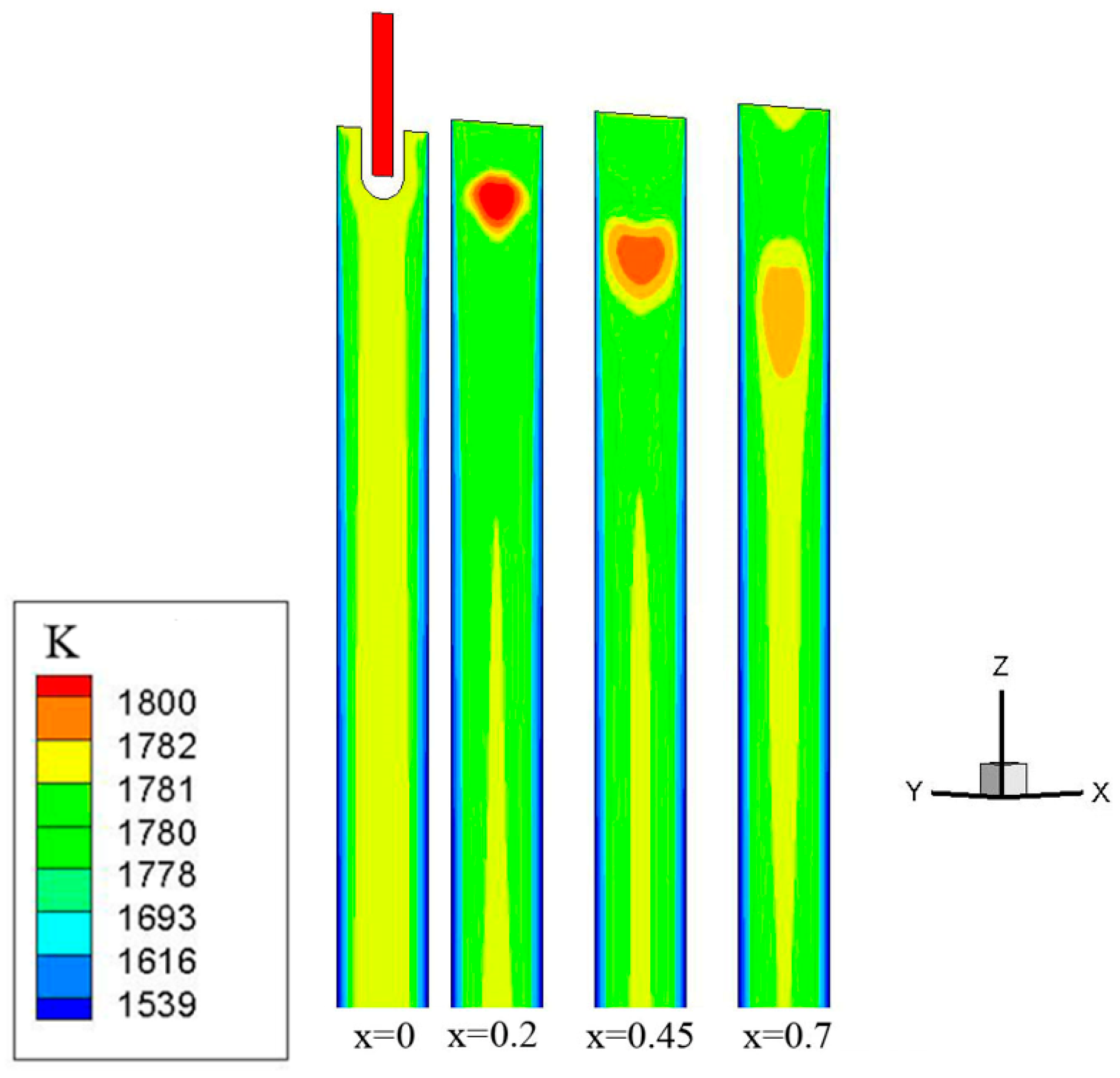
The distribution of steel liquid temperature at different heights is shown in Figure 5. Under the cooling effect of the mold, the temperature of the molten steel gradually decreases along the casting direction, and the temperature at the corners of the billet decreases more significantly. The temperature of the molten steel on the path of the two splitting strands located in the upper and lower circulation zones is relatively high, above 1781 K. The temperature range from the center of the billet to the narrow 1/4 section, which is enclosed by the upper annular flow zone and 400 mm below the liquid level, is relatively low and lower than the liquidus temperature. After the billet is removed from the mold, the influence of nozzle injection and upper and lower circulation flow on the symmetry of section temperature distribution gradually weakens. Below 1.5 m from the liquid level, the temperature distribution is roughly symmetrical along the centerline, and the changes in the wide direction are relatively gentle. Heat transfer and solidification are basically no longer affected by the flow of molten steel.

3.3.2. Temperature of Longitudinal Section

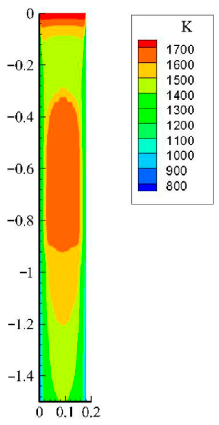
Figure 6 shows the distribution of steel liquid temperature along different longitudinal sections of the slab width direction. From the figure, it can be seen that the temperature field distribution of the molten steel is consistent with the flow field results. The higher temperature molten steel flows out of the nozzle and moves towards the narrow surface of the casting billet. The corresponding high-temperature area can be seen from the temperature distribution diagram of the longitudinal section of the casting billet. Overall, the temperature near the meniscus at the center of the longitudinal section is high and gradually decreases outward and downward. When the temperature drops to the solidus, the liquid steel begins to solidify and forms a solidified shell.

3.3.3. Temperature of Wide Surface

Figure 7 shows the distribution characteristics of the temperature on the wide surface of the outer arc of the casting billet, which can, to some extent, reflect the solidification process of the molten steel. Starting from a position about 10 mm from the liquid level, the wide surface temperature completely drops below the solidus temperature of 1693 K, indicating that the steel liquid in contact with the copper plate has solidified, which is the initial position of steel liquid solidification; The temperature on the outer arc surface of the upper part of the mold is slightly higher at the 1/4 width of the billet towards the water inlet, which is roughly consistent with the mainstream flow line. It can be inferred that it is caused by the rapid transfer of high-temperature steel heat from the centerline to the copper plates on both sides. In the middle and lower parts of the mold, the influence of molten steel at the nozzle on surface temperature gradually weakens, and the temperature at the center of the wide surface at the mold outlet drops to 1380 K.

3.3.4. Temperature of Narrow Surface

Figure 8 shows the distribution characteristics of temperature on the narrow surface of the billet. The distance between the narrow surface primary shell and the meniscus is 20 mm, and the initial position and growth of the shell are not synchronized with the wide surface, which is worth noting. In addition, a narrow impact point of 315 mm below the liquid level formed a high-temperature zone near the impact point, although the temperature is lower than the solidus, its low point is only 100 mm away from the mold outlet. When casting narrow-section steel grades, the erosion of the steel liquid on the billet shell will be more obvious. The temperature at the narrow center of the mold outlet drops to 1550 K.

4. Conclusions

(1)
After the steel liquid reached the narrow surface and formed a certain impact on it, some of the steel liquid flowed towards the meniscus while the other part moved towards the outlet of the mold, forming two main streams: upward flow and downward flow. The vortex center position in the upper reflux zone was (0.565 m, −0.179 m), and the vortex center position in the lower reflux zone was (0.524 m, −0.455 m). The impact position of the narrow surface was 315 mm from the meniscus.
(2)
When the steel liquid reached the meniscus in the upper annular flow zone, the velocity component perpendicular to the liquid surface direction reached a local extreme value, and the horizontal flow velocity parallel to the liquid surface direction was also higher, resulting in the maximum turbulence kinetic energy of the centerline reaching 0.00284 m2∙s−2, 108 mm from the narrow surface. In the area from the narrow surface to 1/4 width of the billet, the turbulent kinetic energy of the center line and the near inner and outer arc copper plate steel liquid was high, and the fluctuation of the liquid level and the inflow of slag were easily disturbed. It was a high-incidence area for longitudinal cracking and bonding of the billet, and attention should be paid to this in the design of the nozzle and flow field optimization.
(3)
The temperature of the steel liquid on the path of the two splitting strands located in the upper and lower circulation zones was relatively high, above 1781 K. The temperature range from the center of the billet to the narrow 1/4 section, which was enclosed by the upper annular flow zone and 400 mm below the liquid level, was relatively low and lower than the liquidus temperature.

Author Contributions

Data curation, F.D., T.L. and S.Z.; Writing—original draft, G.L. All authors have read and agreed to the published version of the manuscript.

Funding

This research received no external funding.

Institutional Review Board Statement

Not applicable.

Informed Consent Statement

Not applicable.

Data Availability Statement

The original contributions presented in this study are included in the article. Further inquiries can be directed to the cor-responding author(s).

Conflicts of Interest

Author Tianyi Li was employed by the company Offshore Oil Engineering Co., Ltd. The remaining authors declare that the research was conducted in the absence of any commercial or financial relationships that could be construed as a potential conflict of interest.

References

  1. Srinivas, P.S.; Mishra, D.K.; Kulkarni, A.B.; Gupta, R.; Korath, J.M.; Jana, A.K. Investigation of vortex flow patterns at the meniscus in a water caster mold. Can. Metall. Q. 2020, 59, 211–232. [Google Scholar] [CrossRef]
  2. Zhao, P.; Piao, R.X. Lattice boltzmann method modeling of the evolution of coherent vortices and periodic flow in a continuous casting mold. Metals 2022, 12, 572. [Google Scholar] [CrossRef]
  3. Zhi, Q.; Niu, J.P.; Tan, X.R.; Rong, P.; Liu, Y.; Chen, Y.Q.; Liu, W.H. Effect of scanning process and heat treatment on microstructure and mechanical property of inconel 718 fabricated by selective laser melting. J. Mater. Eng. Perform. 2024, 32, 9515–9524. [Google Scholar] [CrossRef]
  4. Saeedipour, M.; Pirker, S. Analysis of hysteresis in the regime transition of cocurrent liquid-gas flow. Steel Res. Int. 2022, 93, 2100800. [Google Scholar] [CrossRef]
  5. Chen, W.; Ren, Y.; Zhang, L.F. Large eddy simulation on the two-phase flow in a water model of continuous casting strand with gas injection. Steel Res. Int. 2019, 90, 1800287. [Google Scholar] [CrossRef]
  6. Glavinic, I.; Galindo, V.; Stefani, F.; Wondrak, T. Contactless inductive flow tomography for real-time control of electromagnetic actuators in metal casting. Sensors 2022, 22, 4155. [Google Scholar] [CrossRef] [PubMed]
  7. Wang, S.J.; Xu, P.; Zhou, Y.Z.; Duan, H.M.; Chen, D.F.; Long, M.J. The effect of mold structure and cooling parameters on heat transfer during billet high-speed continuous casting. Materials 2023, 16, 3361. [Google Scholar] [CrossRef] [PubMed]
  8. Kim, H.S.; Kim, J.J.; Oh, K.S. A simplified model for semi-continuous casting of steel. J. Mater. Eng. Perform. 2023, 32, 4064–4070. [Google Scholar] [CrossRef]
  9. Pujol, S.; Bedirhanoglu, I.; Donmez, C.; Dowgala, J.D.; Eryilmaz-Yildirim, M.; Klaboe, K.; Koroglu, F.B.; Lequesne, R.D.; Ozturk, B.; Pledger, L.; et al. Quantitative evaluation of the damage to RC buildings caused by the 2023 southeast Turkey earthquake sequence. Earthq. Spectra 2024, 40, 505–530. [Google Scholar] [CrossRef]
  10. Narayan, N.M.; Gopalkrishna, S.B.; Mehdi, B.; Ryll, S.; Specht, E.; Fritsching, U. Multiphase numerical modeling of boiling flow and heat transfer for liquid jet quenching of a moving metal plate. Int. J. Therm. Sci. 2023, 194, 108587. [Google Scholar] [CrossRef]
  11. Yang, Y.W.; Luo, S.; Wang, W.L.; Zhu, M.Y. Multiphase solidification modeling of solidification structure evolution and macrosegregation of round bloom continuous casting process with mold electromagnetic stirring and final electromagnetic stirring. Steel Res. Int. 2023, 95, 2300446. [Google Scholar] [CrossRef]
  12. Lu, J.Z.; Pan, W.M.; Wang, W.L.; Dou, K. Full-process numerical simulation of flow, heat transfer and solidification for hot stamping steel manufactured via thin slab continuous casting process. MMTB 2024, 55, 3237–3253. [Google Scholar] [CrossRef]
  13. Xie, Q.H.; Ni, P.Y.; Tanaka, T.; Ersson, M.; Li, Y. Flow field, heat transfer and inclusion behavior in a round bloom mold under effect of a swirling flow submerged entry nozzle. J. Iron Steel Res. Int. 2023, 30, 1211–1221. [Google Scholar] [CrossRef]
  14. Li, G.; Tu, L.F.; Wang, Q.Q.; Zhang, X.B.; He, S.P. Fluid flow in continuous casting mold for ultra-wide slab. Materials 2023, 16, 1135. [Google Scholar] [CrossRef] [PubMed]
  15. Zhang, S.Y.; Sun, Y.W.; Liu, Z.Y.; Sun, M.J.; Liu, X.M.; Mu, W.Z.; Liu, T.; Wang, Q. Mechanism of inclusions control influenced by electromagnetic swirling flow in nozzle compared to mold electromagnetic stirring. Materialstoday 2025, 44, 112003. [Google Scholar] [CrossRef]
  16. Wang, S.B.; Cai, Z.Z.; Zhu, M.Y. Behavior of shell initial solidification in ultra-large beam blank continuous casting mold. MMTB 2025, 56, 1588–1604. [Google Scholar] [CrossRef]
  17. Takatani, K. Effects of electromagnetic brake and meniscus electromagnetic stirrer on transient molten steel flow at meniscus in a continuous casting mold. ISIJ Int. 2003, 6, 915–922. [Google Scholar] [CrossRef]
  18. Li, B.K.; Tsukihashi, F. Effects of electromagnetic brake on whirlpool flows in thin slab continuous casting mold. ISIJ Int. 2006, 12, 1833–1838. [Google Scholar] [CrossRef]
  19. Shamsi, M.R.R.I.; Ajmani, S.K. Three dimensional turbulent fluid flow and heat transfer mathematical model for the analysis of a continuous slab caster. ISIJ Int. 2007, 3, 433–442. [Google Scholar] [CrossRef]
  20. Lu, B.W.; Yuan, F.L.; Wang, H.L.; Bai, H. Water model experimental study on the behavior of fluid flow in slab caster mold. Res. Iron Steel 2015, 43, 24–27. [Google Scholar] [CrossRef]
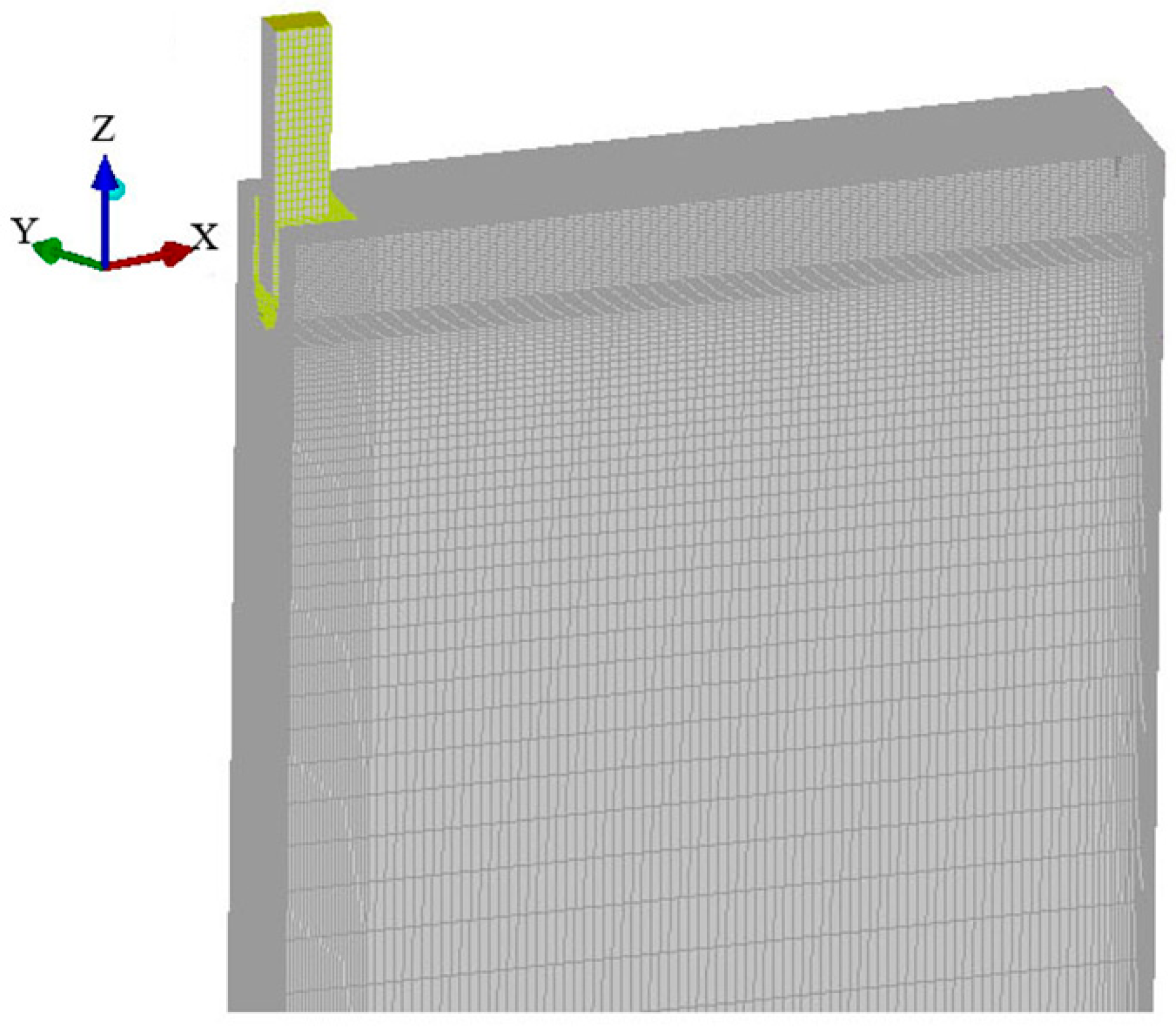
Figure 1. Diagram of the billet model.
Computation 13 00257 g001
Figure 2. The temperature contours of molten steel in the mold.
Computation 13 00257 g002
Figure 3. The flow field contours of molten steel in the mold.
Computation 13 00257 g003
Figure 4. Turbulent kinetic energy at free surface.
Computation 13 00257 g004
Figure 5. Variation and distribution of steel temperature at different heights.
Computation 13 00257 g005
Figure 6. Slab longitudinal section temperature field.
Computation 13 00257 g006
Figure 7. Temperature contours at the outer arc width face.
Computation 13 00257 g007
Figure 8. Temperature contours at the outer arc narrow face.
Computation 13 00257 g008
Table 1. Main design details of caster.
ItemValue
Mold height (mm)1000
Slab width (mm)1800
Slab thickness (mm)180
Nozzle immersion depth (mm)120
Casting speed (m·min−1)1.3
Density of steel (kg·m−3)7080
Viscosity of steel (kg·m−1·s−1)0.0055
Pour point (°C)1530
Liquidius temperature (°C)1510
Solidus temperature (°C)1420
Specific heat of steel (J∙kg−1∙°C −1)740
Latent heat (J∙kg−1)274,950
Steel thermal conductivity(W∙m−1∙K−1)31
Average heat flux (MW∙m−2)1.35
entrance flow rate (m/s)1.1
Disclaimer/Publisher’s Note: The statements, opinions and data contained in all publications are solely those of the individual author(s) and contributor(s) and not of MDPI and/or the editor(s). MDPI and/or the editor(s) disclaim responsibility for any injury to people or property resulting from any ideas, methods, instructions or products referred to in the content.