Article

Advanced Dynamic Responses of Thick FGM Spherical Shells Analyzed Using TSDT Under Thermal Vibration

Department of Mechanical Engineering, Hsiuping University of Science and Technology, Taichung 412406, Taiwan
Computation 2025, 13(10), 245; https://doi.org/10.3390/computation13100245
Submission received: 28 July 2025 / Revised: 15 September 2025 / Accepted: 19 September 2025 / Published: 20 October 2025
(This article belongs to the Section Computational Engineering)

Abstract

The effect of third-order shear deformation theory (TSDT) on thick functionally graded material (FGM) spherical shells under sinusoidal thermal vibration is investigated by using the generalized differential quadrature (GDQ) numerical method. The TSDT displacement field and an advanced nonlinear shear correction coefficient are used to derive the equations of motion for FGM spherical shells. The simple stiffness of FGM spherical shells under a temperature difference along the linear vs. z-axis direction is considered in the heat conduction equation. The dynamic GDQ discrete equations of motion subjected to thermal load and inertia terms can be expressed in matrix form. A parametric study of environmental temperature, FGM power-law index, and advanced nonlinear shear correction on thermal stress and displacement is conducted under the vibration frequency of a simply homogeneous equation and applied heat flux frequency. This is a novel method for obtaining the numerical GDQ results, comparing cases with linear and advanced nonlinear shear correction. The novelty of the present work is that an advanced varied-value type of shear correction coefficient can be successfully used in the thick-walled structure of FGM spherical shells subject to thermal vibration while considering the nonlinear term of TSDT displacements. The purpose of the present work is to investigate the numerical thermal vibration data for a two-material thick FGM spherical shell.

Graphical Abstract

1. Introduction

Many studies have proposed methods for investigating spherical shells. In 2021, Tang and Dai [1] used the Galerkin method to study the nonlinear forced vibration of carbon-fiber-reinforced polymer (CFRP) spherical shell panels under hygrothermal effects. In 2021, Stampouloglou et al. [2] used an exact analytical approach to study displacement and stress in static fields of non-homogeneous isotropic spherical shells under the effect of a radially varying temperature field. In 2021, Papargiri et al. [3] used an analytical method with the effect of electric excitation to study a three-shell spherical human head model in electroencephalography (EEG). In 2021, Li et al. [4] presented experimental and analytical methods to study the effect of dynamic impact loads on the deformation and failure of thin spherical shells. In 2021, Kumar and Kumar [5] used the first-order shear deformation theory (FSDT) model of displacements with the effects of a constant shear correction factor and environmental temperature to study the vibration of functionally graded material (FGM) stiffened shallow shells. In 2019, Heydarpour et al. [6] used the layerwise differential quadrature method (LW-DQM), non-uniform rational B-spline (NURBS) scheme, and Newton–Raphson iterative algorithm to obtain numerical transient results for the temperature and displacement of FGM graphene-platelet-reinforced composite (GPLRC) spherical shells under thermal load and a thermal environment. In 2016, Ranjbar and Alibeigloo [7] used the differential transform method (DTM) and Laplace transform method to obtain dynamic numerical solutions for the stress, displacement, and temperature of FGM spherical shells under thermal load. In 2025, Bacer et al. [8] presented natural convection in a spherical shell using the finite-difference meshless method. In 2025, Zhang et al. [9] used an iteration method for heat conduction and the state-space method for the static equilibrium equation of an FGM spherical shell. In 2025, Wiegold et al. [10] presented the thermo-mechanical results of a hollow-sphere shell by using the numerical isogeometric finite element method (FEM).
Many studies have been conducted on the effect of HSDT on thick FGM shells. In 2024, Mamandi [11] investigated the yield condition for thick FGM spherical shells under thermal and pressure loads by using a neural network (NN) approach. In 2020, Zannon et al. [12] investigated the fundamental frequencies of thick FGM spherical shells with third-order shear deformation theory (TSDT) and no external loads. In 2012, Dai et al. [13] investigated the responses of nonlinear FGM spherical shells using the numerical method of lines. In 2021, Dastjerdi et al. [14] presented a general nonlinear type of FGM shell structure. In 2017, Khoa and Tung [15] investigated the nonlinear response of FGM spherical shells with elastic bases and pressure loads. In 2015, Nejad et al. [16] investigated the creep of rotating thick FGM cylindrical vessels under pressure loads. In 2019, Nematollahi et al. [17] investigated thick FGM spherical vessels under thermal, magnetic, and pressure loads. In 2017, Hajlaoui et al. [18] investigated the nonlinear vibrations of thick FGM cylindrical shells with HSDT based on an enhanced assumed strain (EAS) model. In 2023, Narendra and Pradhan [19] investigated vibration control using a magnetostrictive layer on thick FGM shells with HSDT. In 2025, Meftah et al. [20] investigated the fundamental frequencies of thick FGM plates with HSDT and shear correction effects. Few articles have discussed HSDT and shear correction effects together in thermal vibration numerical studies of the time response and transient response of displacements and stresses in thick FGM spherical shells.
Many types of shear correction coefficients have been used in the stiffness integral of FGM spherical shells. A constant value type, e.g., 5/6 or 2/3, can be used in a thin-walled structure with FSDT displacement. A varied-value type can be used in a thick-walled structure without the nonlinear term of TSDT displacement. Another advanced varied-value type can be used in a thick-walled structure with the nonlinear term of TSDT displacement. Many generalized differential quadrature (GDQ) computations in FGM structures considering heating loads were presented. In 2021, Hong [21] used the GDQ numerical method to present thermal vibration of thick FGM spherical shells using TSDT and a varied-value type of shear correction coefficient without the nonlinear term of TSDT. In 2022, Hong [22] used the GDQ numerical method to present thermal vibration of thick FGM plates using TSDT and an advanced varied-value type of shear correction coefficient with the nonlinear term of TSDT. It is novel and interesting to study GDQ computations using TSDT and an advanced varied-value type of shear correction coefficient for FGM spherical shells under four-edge simply supported boundary conditions. The contribution of the advanced varied-value type of shear correction coefficient used in the present study lies in its application to thick-walled spherical curvature, where combining it with the advanced nonlinear varied-value type of shear correction leads to qualitatively new insights beyond those of previous studies [21] that used a linear varied-value type of shear correction coefficient. Many parametric effects of environmental temperature, FGM power-law index, advanced varied-value type of shear correction coefficient, and vibration frequency of the simply homogeneous equation on FGM spherical shells are investigated.
The physical formulation of the present problem is described as follows: Nonlinear displacements as a function of the z-axis direction and the sinusoidal form of vibration are considered in the TSDT equations. Thermal loads in dynamic sinusoidal form and temperature difference are considered in heat conduction equations. Thermal stresses and strains due to temperature difference are considered in the constituents of FGM spherical shells. Dynamic equilibrium differential equations based on TSDT can be obtained under thermal loads. Then numerical thermal vibration GDQ data can be obtained by including the effect of advanced varied shear values on a thick-walled FGM spherical shell. The research objectives are to investigate the numerical thermal vibration data of stress and displacement for a two-material thick-walled FGM spherical shell. A brief description of the structure of the present work is as follows: in the Materials and Methods section, the thick-walled FGM spherical shell, TSDT equations, and thermal load equations are presented; in the Theory and Calculation section, the dynamic equilibrium differential equations and dynamic GDQ discrete equations of motion are presented; in the Results section, dynamic convergence, time responses, parametric effects, and transient responses are presented.

2. Materials and Methods

It is well known that FGMs exhibit a continuous variation in material properties from the surface of FGM material 1 to that of FGM material 2, according to power-law functions. A two-material FGM spherical shell for 0° ≤ ∅ ≤ 90° under thermal load at temperature difference ∆T is shown in Figure 1, where h 1 is the thickness of FGM material 1, the inner constituent; h 2 is the thickness of FGM material 2, the outer constituent; and L is the axial length of FGM shells in the x direction. The z-axis is defined along the thickness direction, and the mid-surface is located at z = 0; the region above the mid-surface is positive, z > 0, and the region below the mid-surface is negative, z < 0. A point in the coordinates of spherical axes (r,θ,∅) can be related to Cartesian coordinates (x, y, z) with the relation equations x = r sin ∅ cos θ, y = r sin ∅ sin θ, and z = r cos ∅, where r is the radius of FGM shells. When the angle = 90 ° , the coordinates of spherical axes become those of cylindrical axes. The angle θ denotes the circumferential direction of the shells. The angle ∅ denotes the direction of z-axis and the direction of the radius in the spherical shells. The material property power-law functions of FGM shells are used in functions of the power-law index R n and environmental temperature T [21].

2.1. TSDT Displacements

The nonlinear displacements u , v , and w of thick FGM spherical shells for a given ∅ angle are used in c 1 and in time t -dependent TSDT equations [21] as follows. In the preliminary study, it is assumed that there is constant transverse displacement across the thickness direction of the shells, without the function of z.
u = u 0 ( x , θ , t ) + z ϕ x ( x , θ , t ) c 1 z 3 ( ϕ x + w x ) ,
v = v 0 ( x , θ , t ) + z ϕ θ ( x , θ , t ) c 1 z 3 ( ϕ θ + w R θ ) ,
w = w ( x , θ , t ) ,
where u 0 , v 0 , and w are tangential and transverse displacements in the x -, θ -, and z -axes direction, respectively. ϕ x and ϕ θ are the shear rotations; R is the mid-surface radius. The expression c 1 = 4 3 ( h * ) 2 is used, where h * is the total thickness of FGM shells. And usually, the sinusoidal form of vibration for displacement and shear rotations is used as follows [21]:
u 0 ( x , θ , t ) = u 0 ( x , θ ) sin ( ω m n t ) ,
v 0 ( x , θ , t ) = v 0 ( x , θ ) sin ( ω m n t ) ,
w ( x , θ , t ) = w ( x , θ ) sin ( ω m n t ) ,
ϕ x ( x , θ , t ) = ϕ x ( x , θ ) sin ( ω m n t ) ,
ϕ θ ( x , θ , t ) = ϕ θ ( x , θ ) sin ( ω m n t ) ,
where ω m n is the natural frequency with the mode shape specified by subscripts m and n . ω m n can be obtained from the simply homogeneous equation under no external loads.

2.2. Thermal Load Under ∆T

The normal stresses σ x , σ θ and shear stresses σ x θ , σ θ z , σ x z in the thick FGM spherical shells under ∆T for the (k)th constituent are expressed as follows [21]:
σ x σ θ σ x θ ( k ) = Q ¯ 11 Q ¯ 12 Q ¯ 16 Q ¯ 12 Q ¯ 22 Q ¯ 26 Q ¯ 16 Q ¯ 26 Q ¯ 66 ( k ) ε x α x Δ T ε θ α θ Δ T ε x θ α x θ Δ T ( k ) ,
σ θ z σ x z ( k ) = Q ¯ 44 Q ¯ 45 Q ¯ 45 Q ¯ 55 ( k ) ε θ z ε x z ( k ) ,
where α x , α θ and α x θ are the coefficients of thermal expansion and thermal shear. Q ¯ i j is the stiffness of FGM shells. ε x , ε θ , and ε x θ are in-plane strains. ε θ z and ε x z are shear strains that are not negligible in the thick-thickness study. The ∆T expression, assumed to satisfy the boundary ∆T = 0 along mid-surface z = 0 and initial conditions ∆T = 0 at t = 0 for the thermal load, can be expressed in linear vs. z-axis direction and sinusoidal form between the FGM shell and curing area as follows:
T = z h * T ¯ 1 s i n ( π x / L ) s i n ( π θ ) s i n ( γ t ) ,
where γ is the applied heat flux frequency and T ¯ 1 is the temperature amplitude.
The heat conduction equation for ∆T in the FGM spherical coordinates used is as follows [21]:
K 2 T x 2 + 2 T R 2 θ 2 + 2 T ( R s i n ) 2 2 = T t ,
where K = κ f g m / ( ρ f g m C v f g m ) , where κ f g m is the thermal conductivity, ρ f g m is the density, and C v f g m is the specific heat of FGM shells. After the mathematical operation of substituting (11) into (12) with z = R cos , simplified and partially applied for γ derivation only, the following expression for the heat flux frequency equation can be obtained [21]:
L 2 K π 2 [ 1 + L R 2 + ( L π R s i n ) 2 ] γ cos γ t + sin γ t = 0 ,
The γ value of (13) can be solved for a given by a traditional numerical method, e.g., the bisection iterative method.

3. Theory and Calculation

The dynamic equations of motion based on TSDT for a small element in an FGM spherical shell can be obtained in partial differential forms, and the derivatives will be in terms of stresses with respect to x , θ , and z and in terms of displacements with respect to x , θ , and t. After Von Karman strain–displacement relations and v 0 z = v 0 R s i n , u 0 z = u 0 R s i n , w z = ϕ x z = ϕ θ z = 0 are used, dynamic equilibrium differential equations based on TSDT in terms of partial derivatives of displacements and shear rotations subjected to partial derivatives of thermal loads and inertia terms can be obtained in matrix forms, as expressed by (A1) in Appendix A.

3.1. Dynamic GDQ Discrete Equations of Motion

Thus, the dynamic GDQ discrete equations obtained for (A1) can be solved in matrix notation by using the numerical GDQ method with a discretization approach, e.g., for f x | i , j l = 1 N A i , l ( 1 ) f l , j , f θ | i , j l = 1 M B j , m ( 1 ) f i , m used for first-order derivatives of function f ( x , θ ) , etc., where A i , l ( 1 ) and B j , m ( 1 ) denote the weighting coefficients and subscripts i and j are grid point numbers. The stiffness integrals A i s j s , B i s j s , D i s j s , E i s j s , F i s j s , H i s j s , i s , j s = 1 , 2 , 6 and A i * j * , B i * j * , D i * j * , E i * j * , F i * j * , H i * j * , i * , j * = 4 , 5 with advanced k α are expressed in the matrix elements. The stiffness Q ¯ i s j s and Q ¯ i * j * for FGM thick spherical shells with z / R terms cannot be neglected and replaced in the simple forms by using the z/(R sin ∅) term [21]; e.g., Q ¯ 11 = Q ¯ 22 = E f g m 1 ν f g m 2 , Q ¯ 12 = Q ¯ 21 = ν f g m E f g m 1 + z R s i n ( 1 ν f g m 2 ) for elastic modulus and Q ¯ 44 = E f g m 2 ( 1 + ν f g m ) , Q ¯ 55 = Q ¯ 66 = E f g m 2 1 + z R s i n ( 1 + ν f g m ) for shear modulus, Q ¯ 16 = Q ¯ 26 = Q ¯ 45 = 0 , etc. These expressions also contain Poisson’s ratio ν f g m = ν 1 + ν 2 2 and Young’s modulus E f g m = ( E 2 E 1 ) ( z + h * / 2 h * ) R n + E 1 , where h * is the thickness; R n is the power-law exponent parameter; E 1 and E 2 are the Young’s modulus of the FGM constituent material 1 and material 2, respectively; and ν 1 and ν 2 are the Poisson’s ratios of the FGM constituent material 1 and material 2, respectively. The simple Q ¯ i s j s and Q ¯ i * j * forms are used to calculate the stresses and stiffness integrals. They are explained as follows. The power-law function is not used for determining the Poisson’s ratio; instead, an average form for the Poisson ratio is used, i.e., ν f g m = ( ν 1 + ν 2 ) / 2 , since the ν 1 , ν 2 values, e.g., 0.3262, are much smaller in magnitude than the Young’s modulus E 1 , E 1 values, e.g., 201.04 GPa, of material SUS304. Thus, only the dominant Young’s modulus E f g m is used for the calculation of the power-law function, while the other properties ν f g m , ρ f g m , etc., are used simply in average form to find the values for stiffness Q ¯ i s j s , Q ¯ i * j * and integral stiffness A i s j s , B i s j s , D i s j s , E i s j s , F i s j s , H i s j s of rational functions by using the long-division method with the first five terms of quotient polynomials; e.g., approximated forms are A 11 = h * 1 [ ( ν 1 + ν 2 ) / 2 ] 2 ( R n E 1 + E 2 R n + 1 ) , E 11 = ( h * ) 4 ( E 2 E 1 ) 1 [ ( ν 1 + ν 2 ) / 2 ] 2 [ 1 R n + 4 3 2 ( R n + 3 ) + 3 4 ( R n + 2 ) 1 8 ( R n + 1 ) ] , etc. Then the result values of stresses can be calculated with acceptable accuracy.
The expression of an advanced varied-type k α can be derived from the energy equivalence principle and can be expressed briefly as follows [22]:
k α = 1 h * F G M Z S V F G M Z I V ,
where parameters of FGMZSV and FGMZIV are functions of E 1 , E 2 , c 1 and R n . As FGMZIV is a function of ( h * ) 5 and FGMZSV is a function of ( h * ) 6 , the advanced k α is not a function of h* and has a non-dimensional value. The advanced k α values are functions of c 1 , R n , and T . When the nonlinear term c 1 of TSDT is used, the corresponding nonlinear k α term is called. When the linear term c 1 = 0 for FSDT is used, the corresponding linear k α term is called. A full derivation for advanced coefficient k α expression, including its physical admissibility in bounds, positivity, and limiting cases for constant shear factors in FSDT, is presented in (A2)–(A20) in Appendix A.

3.2. GDQ Implementation

For a grid point (i,j), the dynamic GDQ discrete equations of motion can be rewritten into the matrix form in the following GDQ expression:
[ A ] { W * } = { B } ,
where {W*} = {U2,2, …, UN−1,M−1, V2,2, …, VN−1,M−1, W2,2, …, WN−1,M−1, ϕ x 2,2, …, ϕ x N−1,M−1, ϕ θ 2,2, …, ϕ θ N−1,M−1}t, where U = u 0 / L , V = v 0 / R , W = w / h * , and N and M are the grid point numbers. When all of the elements in [ A ] are prepared and implemented by using the Lahey-Fujitsu Fortran 7.8 program, the N**th-order unknown { W * } can be obtained under N**th-order external loads { B } for four sides simply supported with N** = 5(N − 2)(M − 2) by using the following grid coordinates x i and θ j :
x i = 0.5 [ 1 cos i 1 N 1 π ] L ,   i = 1 , 2 , , N ,
θ j = 0.5 [ 1 cos j 1 M 1 π ] R ,   j = 1 , 2 , , M ,

4. Results

FGM material 1, SUS304, and FGM material 2, Si3N4, are used for numerical computations in thick FGM spherical shells under the advanced nonlinear k α effect. The parameters used are h * = 1.2 mm, h 1 = h 2 = 0.6 mm, L/R = 1, and 0° ≦ ∅ ≦ 90° for the geometric values under sinusoidal thermal load T ¯ 1 = 100 K and ω 11 . Numerical GDQ values of center displacement w ( L / 2 , 2 π / 2 ) (mm) and normal stress σ x (GPa) are computed and studied. Four-side simply supported (SS-SS) boundary conditions are shown as follows: at x = 0 and x = L , N x x = M ¯ x x = v 0 = w = ϕ θ = 0 ; at θ = 0 and θ = 2 π , N θ θ = M ¯ θ θ = u 0 = w = ϕ x = 0 . Under sinusoidal temperature loading ∆T, the following applicable boundary conditions can be obtained:
At   x = 0   and   x = L :   u 0 x = v 0 = w = ϕ x x = ϕ θ = 0 ,
At   θ = 0   and   θ = 2 π :   u 0 = v 0 θ = w = ϕ x = ϕ θ θ = 0 .

4.1. Dynamic Convergence

An advanced dynamic convergence study of w ( L / 2 , 2 π / 2 ) at t = 6 s under T = 100 K, nonlinear c 1 = 0.925925/mm2, and linear c 1 = 0 at = 10 ° , for L / h * = 10 with γ = 0.2618004/s and L / h * = 5 with γ = 0.261805/s, is presented in Table 1. The use of the advanced nonlinear k α value and R n values to calculate ω 11 with a simply homogeneous equation is detailed as follows: In the L / h * = 5, c 1 = 0.925925/mm2 case, (a) using R n = 0.5 and k α = −0.539419, ω 11 = 0.001961/s is obtained; (b) using R n = 1 and k α = −0.922719, ω 11 = 0.015267/s is obtained; (c) using R n = 2 and k α = 9.852628, ω 11 = 0.005019/s is obtained. In the L / h * = 5, c 1 = 0/mm2 case, (d) using R n = 0.5 and k α = 1.136032, ω 11 = 0.042820/s is obtained; (e) using R n = 1 and k α = 1.273499, ω 11 = 0.017667/s is obtained; (f) using R n = 2 and k α = 1.317037, ω 11 = 0.035069/s is obtained. The error accuracy is 0.000047 for the w ( L / 2 , 2 π / 2 ) value in the c 1 = 0.925925/mm2, R n = 0.5, and L / h * = 10 cases. The grid points N × M = 13 × 13 can be accepted in very good convergence for GDQ computations of w ( L / 2 , 2 π / 2 ) under thermal vibration with nonlinear TSDT and advanced k α . The lower 11 × 11 is also sufficient for w ( L / 2 , 2 π / 2 ) convergence; one can also use it if one wants.

4.2. Time Responses of w ( L / 2 , 2 π / 2 ) and σ x

Time responses of w ( L / 2 , 2 π / 2 ) and σ x for the thermal vibration at = 45 ° are calculated with the advanced nonlinear k α under varied γ of applied heat flux. γ values decreasing from γ = 15.707960/s at t = 0.1 s to γ = 0.523601/s at t = 3.0 s are used for L / h * = 5, and γ values decreasing from γ = 15.707963/s at t = 0.1 s to γ = 0.523599/s at t = 3.0 s are used for L / h * = 10. Figure 2 shows the response values of w ( L / 2 , 2 π / 2 ) (mm) versus t(s) with c 1 = 0.925925/mm2, advanced nonlinear k α vs. linear k α for L / h * = 5 and 10, R n = 1, T = 600 K, and t = 0.1–3.0 s. In Figure 2a, the maximum value of w ( L / 2 , 2 π / 2 ) is 3.3419 mm and occurs at t = 0.1 s for the nonlinear k α of L / h * = 5 with γ = 15.707964/s. The w ( L / 2 , 2 π / 2 ) values have a decreasing tendency with time, reducing to 0.0951 mm in nonlinear k α and reducing to 0.0495 mm in linear k α cases for L / h * = 5. The w ( L / 2 , 2 π / 2 ) values in the linear k α case are underestimated and smaller than those in the nonlinear k α case with less accuracy, where accuracy = (0.0951 − 0.0495)/0.0951 = 0.4788, at the corresponding time for L / h * = 5. In Figure 2b, the maximum value of w ( L / 2 , 2 π / 2 ) is 31.1766 mm and occurs at t = 0.1 s for the linear k α of L / h * = 10 with γ = 15.707963/s. The values of w ( L / 2 , 2 π / 2 ) have a decreasing tendency with time, reducing to 0.7888 mm in nonlinear k α and reducing to 1.0914 mm in linear k α cases for L / h * = 10. The w ( L / 2 , 2 π / 2 ) values in the linear k α case are overestimated and greater than those of the nonlinear k α case with greater accuracy, where accuracy = (1.0914 − 0.7888)/0.7888 = 0.3834, at the corresponding time for L / h * = 10.
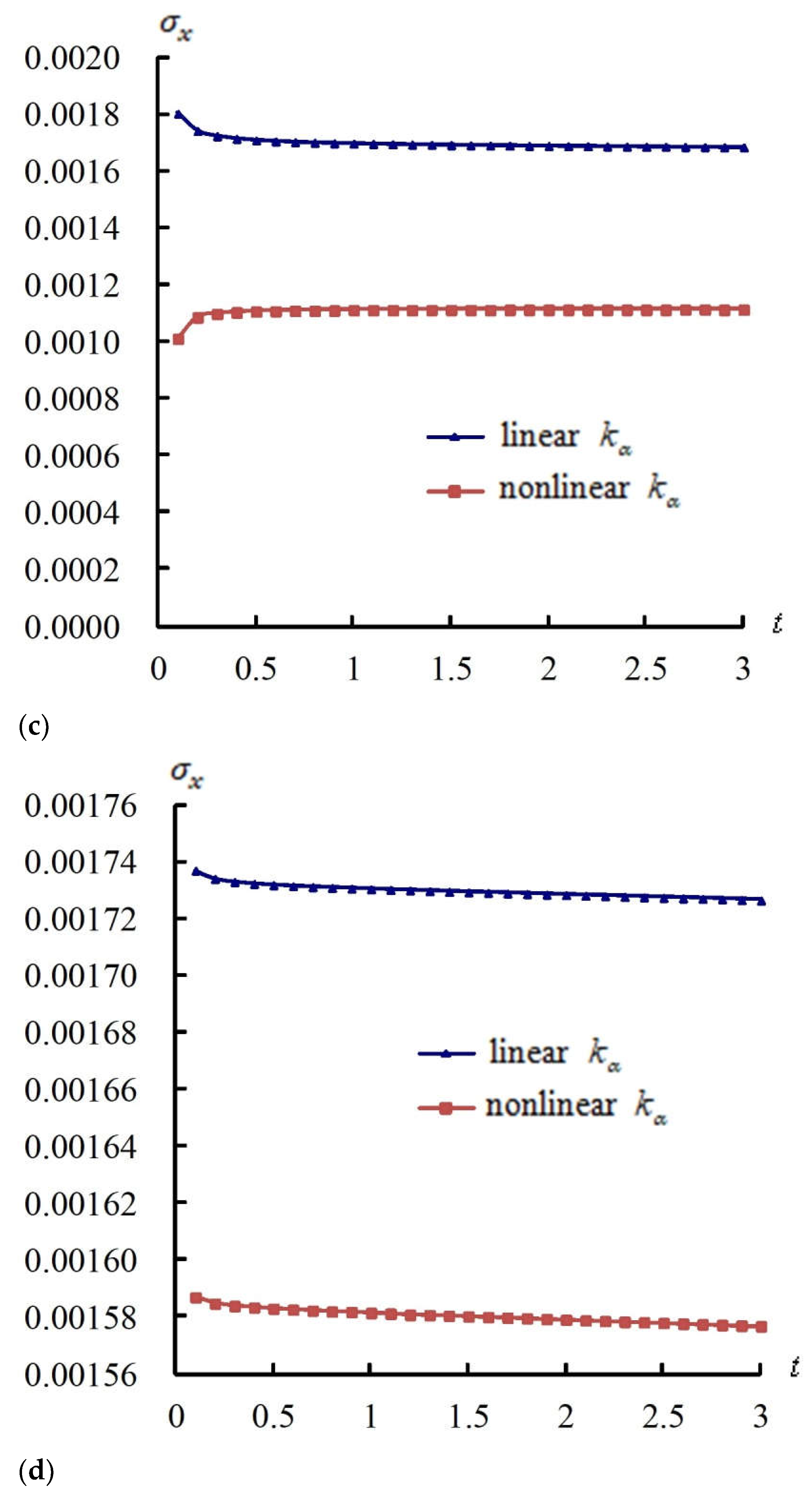
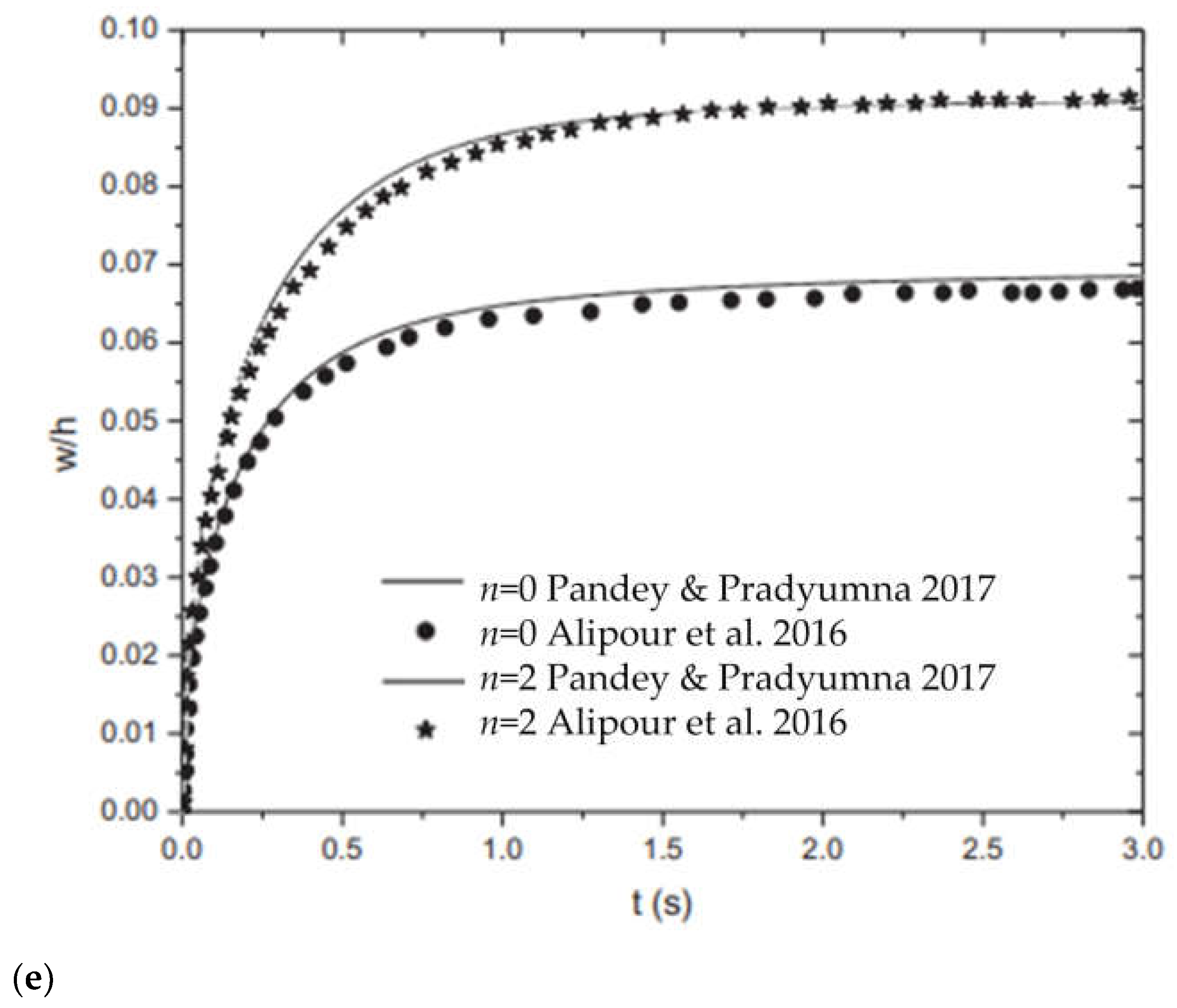
Also, Figure 2 shows the time responses of σ x at z = −0.5 h * and = 45 ° for R n = 1 and L / h * = 5 and 10 with c 1 = 0.925925/mm2. In Figure 2c, the maximum value of σ x is 0.0018 GPa and occurs at t = 0.1 s of periods t = 0.1–3 s for the linear k α of L / h * = 5. The values of σ x have a constant tendency with time in the nonlinear k α case, converging at 0.0011 GPa, and the linear k α case, converging at 0.0016 GPa, for L / h * = 5. The values of σ x in the linear k α case are overestimated and greater than those of the nonlinear k α case, where accuracy = (0.0016 − 0.0011)/0.0011 = 0.5128, at the corresponding time for L / h * = 5. In Figure 2d, the maximum value of σ x is 0.0017 GPa and occurs at t = 0.1 s of periods t = 0.1–3 s for the linear k α of L / h * = 10. The values of σ x have a constant tendency with time in the nonlinear k α case, converging at 0.0015 GPa, and the linear k α case, converging at 0.0017 GPa, for L / h * = 10. The values of σ x in the linear k α case are overestimated and greater than those of the nonlinear k α case, where accuracy = (0.0017 − 0.0015)/0.0015 = 0.0948, at the corresponding time for L / h * = 10. A comparison of the numerical results with one of the existing methods, especially the FEM, would be advisable. Published articles have presented numerical studies of the effects of HSDT on the thermal vibration and time response of displacements in FGM shells. In 2017, Pandey and Pradyumna presented a study [23]; in 2016, Alipour et al. [24] presented the time response of displacements for a thick FGM sandwich shell under rapid heat, and there is a similar convergence tendency for the compared results in which w ( L / 2 , 2 π / 2 ) converges to 0.0951 mm at t = 3.0 s in nonlinear case and converges to 0.0495 mm at t = 3.0 s in linear case for Figure 2a FGM spherical shells where L / h * = 5 and R n = 1, converges to 0.7888 mm at t = 3.0 s in the nonlinear case, and converges to 1.0914 mm at t = 3.0 s in the linear case for Figure 2b FGM spherical shells where L / h * = 10 and R n = 1. As shown by the compared data listed in Figure 2e for L / h * = 14.285714 of the FGM plate, the displacement w = 0.4655 mm at t = 3.0 s found in volume fraction index n = 0 ( R n = 0) case, w = 0.637 mm at t = 3.0 s for the volume fraction index n = 2 ( R n = 2) case; thus, the displacement w = 0.5512 mm at t = 3.0 s can be found as the average in the n = 1 ( R n = 1) case. So, there is a small difference for the convergence value of 0.7888 mm due to high environmental temperature T = 600 K for the middle thick-walled ratio L / h * = 10 of the FGM spherical shell with respect to 0.5512 mm due to the low environmental temperature T = 300 K for the thin-walled ratio L / h * = 14.285714 of the FGM plate at t = 3.0 s.

4.3. Responses of w ( L / 2 , 2 π / 2 ) and σ x vs. T and R n

Figure 3 shows the response values of w ( L / 2 , 2 π / 2 ) versus T(K) of 100 K, 600 K, and 1000 K and R n values from 0.1 to 10 under c 1 = 0.925925/mm2 and advanced nonlinear k α at = 45 ° for L / h * = 5 and 10 at t = 0.1 s. On curves of w ( L / 2 , 2 π / 2 ) vs. T and R n for L / h * = 5, the maximum value of w ( L / 2 , 2 π / 2 ) is 3.3419 mm and occurs at T = 600 K for R n = 1. The w ( L / 2 , 2 π / 2 ) values all increase with T from T = 600 K to T = 1000 K for all values of R n , except for R n = 1, where there is a decrease with T. Thus, the w ( L / 2 , 2 π / 2 ) value for L / h * = 5 can withstand the higher T = 1000 K for R n = 1. The curves of w ( L / 2 , 2 π / 2 ) vs. T and R n for L / h * = 10 almost overlap, except for R n = 1 at T = 600 K. The maximum value of w ( L / 2 , 2 π / 2 ) is 48.2802 mm and occurs at T = 1000 K for all values of R n . The w ( L / 2 , 2 π / 2 ) values all increase with T from T = 600 K to T = 1000 K for all values of R n . Thus, the w ( L / 2 , 2 π / 2 ) value for L / h * = 10 cannot withstand the higher T = 1000 K at t = 0.1 s. The σ x at z = −0.5 h * versus T (K) and R n was shown under c 1 = 0.925925/mm2, advanced nonlinear k α , and = 45 ° for L / h * = 5 and 10 at t = 0.1 s. On curves of σ x vs. T and R n for L / h * = 5, the values of σ x versus T all increase from T = 100 K to T = 600 K and then all decrease from T = 600 K to T = 1000 K for all values of R n , except for R n = 1, where there is a decrease and then an increase with T. The maximum value of σ x is 0.0018 GPa and occurs at T = 600 K for R n = 2. The σ x of L / h * = 5 can withstand the higher T = 1000 K, except for R n = 1. Curves of σ x (GPa) vs. T and R n for L / h * = 10 are also shown. The values of σ x versus T all increase from T = 100 K to T = 600 K and then all decrease from T = 600 K to T = 1000 K for all values of R n . The maximum value of σ x is 0.0017 GPa and occurs at T = 600 K for R n = 2. The σ x of L / h * = 10 can withstand the higher T = 1000 K for all values of R n at t = 0.1 s.

4.4. Responses of w ( L / 2 , 2 π / 2 ) and σ x vs.

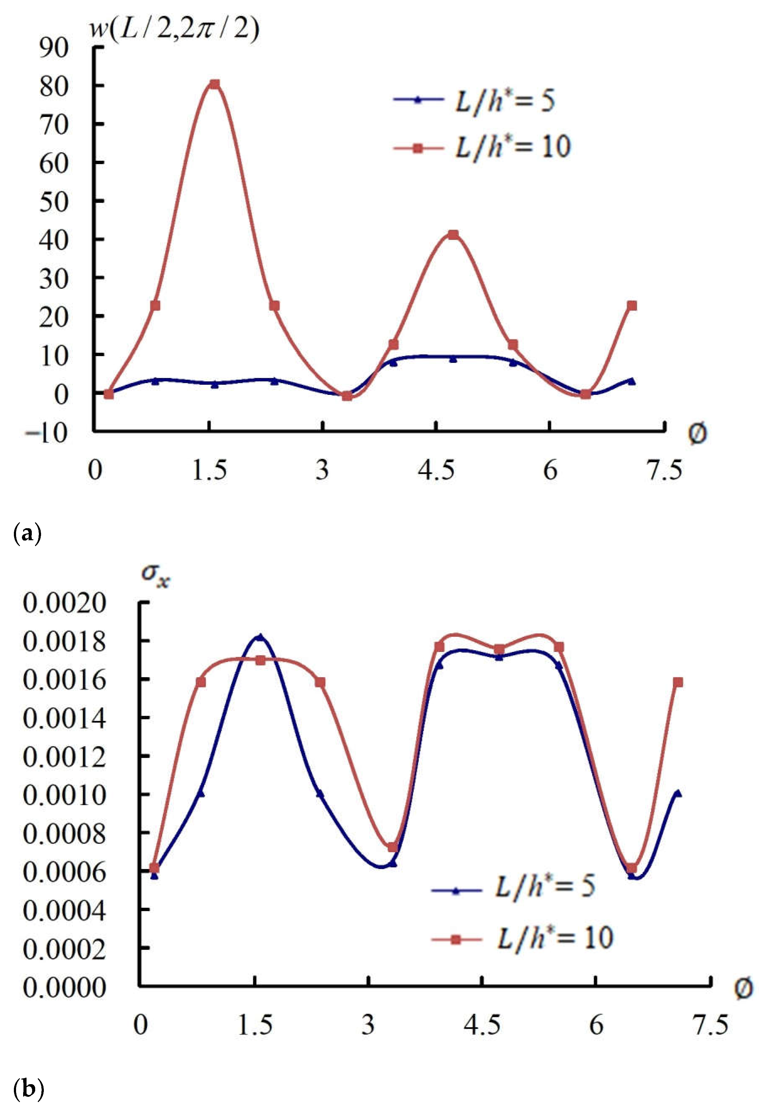
Figure 4 shows the response values of w ( L / 2 , 2 π / 2 ) and σ x versus (radian) for L / h * = 5 and 10 under T = 600 K, R n = 1, c 1 = 0.925925/mm2, and advanced nonlinear k α at t = 0.1 s. The response values of w ( L / 2 , 2 π / 2 ) (mm) versus for thick L / h * = 5 and 10 are shown. Values of w ( L / 2 , 2 π / 2 ) in the L / h * = 10 case sinusoidally oscillate and greater than those of the L / h * = 5 case. The response values of σ x (GPa) at z = −0.5 h * versus for L / h * = 5 and 10 are shown, and the values of σ x in the L / h * = 5 and 10 cases sinusoidally oscillate.

4.5. Transient Responses of w ( L / 2 , 2 π / 2 )

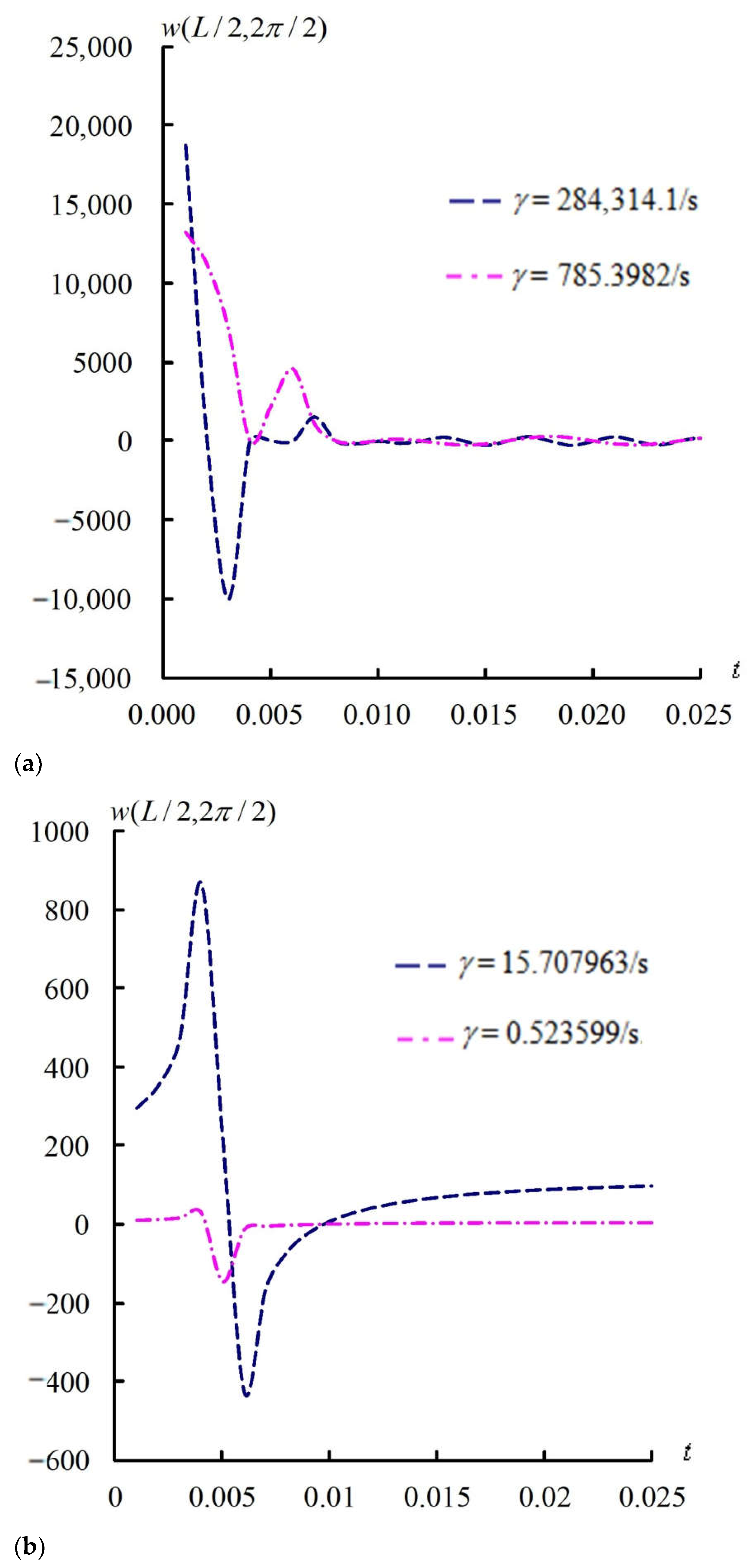
Finally, Figure 5 shows the transient responses w ( L / 2 , 2 π / 2 ) with c 1 = 0.925925/mm2 for L / h * = 10, R n = 1, and fixed ω 11 = 0.000592/s at = 45 ° under T = 600 K, applied heat flux γ , and advanced nonlinear k α for the short period t = 0.001–0.025 s. Comparisons of the advanced transient response w ( L / 2 , 2 π / 2 ) for L / h * = 10 under the super value γ = 284314.1/s and high value γ = 785.3982/s are shown. The transient values of w ( L / 2 , 2 π / 2 ) vs. higher γ all oscillate and decrease for L / h * = 10. Comparisons of the advanced transient response w ( L / 2 , 2 π / 2 ) for thick L / h * = 10 under lower values of γ = 15.707963/s and γ = 0.523599/s are also shown. The transient values of w ( L / 2 , 2 π / 2 ) vs. lower γ all rapidly oscillate and decrease for L / h * = 10. The maximum of w ( L / 2 , 2 π / 2 ) has an unrealistically high value and becomes corrupted when the super high and very high frequency values of applied heat flux are used.

5. Discussion

In consideration of published studies that were presented in the fields of wave propagation analysis by Ebrahimi et al. in 2017 [25], thermally affected wave propagation analysis by Ebrahimi and Barati in 2016 [26], stability analysis by Asrari et al., 2020 [27], and magneto-electro-thermal analysis by Arefi et al. [28] for FGM nanobeams, nanoplates, nanoshells, and nanoplates with porous cores, respectively, it would be very interesting to perform static analyses for nanostructures in the future. Numerical methods were presented in thin plate fields in 2019 by Guo et al. [29], who used a deep collocation method (DCM), and in 2021 by Zhuang et al. [30], who used a deep-autoencoder-based energy method (DAEM). It would also be very interesting to perform numerical experiments using machine learning and deep learning in the future. The transverse displacement, which varies across the thickness direction and includes thermal expansion effects in the transverse direction, was presented in the static expansion analysis by Zhen et al. in 2010 [31].
The constituent material properties P i in the expression P i = P 0 ( P 1 T 1 + 1 + P 1 T + P 2 T 2 + P 3 T 3 ) are functions of coefficients P 1 , P 0 , P 1 , P 2 , and P 3 and temperature T. For FGM material 1 (SUS304) and FGM material 2 (Si3N4), these properties are presented in Table 2 and the work of Hong (2025) [32]. The governing eigenproblem, boundary conditions, and numerical implementation for ω m n are presented in (A21) and (A22) in Appendix A. A brief convergence table for ω 11 (1/s) is presented in Table 3. Benchmarking against homogeneous material shells or thin-shell theory is an independent approach, essential for confirming accuracy and building confidence in the proposed method. This would be possible in future work if the GDQ method is used to find the unknown { W * } in (15). In Figure 2b, the maximum w ( L / 2 , 2 π / 2 ) is 31.1766 mm and occurs at t = 0.1 s, T = 600 K,   = 45 ° , R n = 1, linear k α , L / h * = 10, h * = 1.2 mm, and L/R = 1 under γ = 15.707963/s. It appears large relative to shell thickness; these displacement values greater than 30 mm are simulated ideally and would be used to avoid overshoot and breaking in the structure design preliminarily. The concise table of four-side simply supported boundary conditions including location and displacement/rotation constraints presented in Table 4 can help avoid ambiguity and ensure reproducibility. The parameter ranges and their physical rationale are clearly summarized in Table 5 to make the results more generalizable. It would also be very challenging and interesting to study the numerical results for transverse displacement considered and varied across the thickness direction in the future.

6. Conclusions

The novelty of the work is justified as follows: An advanced varied-value type of shear correction coefficient can be successfully used in thick-walled structures of FGM spherical shells subject to thermal vibration while the nonlinear term of TSDT displacements is considered. The GDQ solutions are calculated and investigated for the displacements and stresses in advanced thermal vibration of thick FGM spherical shells under applied heat flux frequency, vibration frequency values of a simply homogeneous equation, advanced nonlinear k α , and the nonlinear coefficient c 1 term of TSDT. The values of w ( L / 2 , 2 π / 2 ) and σ x in the linear k α case are overestimated and greater than the nonlinear k α case at the corresponding time for L / h * = 10. The w ( L / 2 , 2 π / 2 ) values for L / h * = 5 and 10 can withstand 1000 K and R n = 1. At t = 0.1 s, the σ x of the L / h * = 5 case can withstand 1000 K, except at R n = 1; the σ x of L / h * = 10 case can withstand 1000 K and all values of R n . In the available compared results of reference solutions, there is a little difference for the displacement convergence value of 0.7888 mm due to the high temperature of 600 K for the middle thick-walled ratio L / h * = 10 of an FGM spherical shell with respect to 0.5512 mm due to the low temperature of 300 K for the thin-walled ratio L / h * = 14.285714 of the reference FGM plate at t = 3.0 s.

Funding

This research received no external funding.

Data Availability Statement

The original contributions presented in the study are included in the article; further inquiries can be directed to the corresponding author.

Acknowledgments

The author expresses his thanks to the people who helped with this work and acknowledges the valuable suggestions from the peer reviewers.

Conflicts of Interest

The author declares no conflicts of interest.

Appendix A

The dynamic equilibrium differential equations based on TSDT are listed as follows:
0 0 0 0 0 0 0 0 0 0 c 1 2 H 11 4 c 1 2 H 16 2 c 1 2 H 12 4 c 1 2 H 66 4 c 1 2 H 26 c 1 2 H 22 0 0 0 0 0 0 0 0 0 0
4 w x 4 1 R 4 w x 3 θ 1 R 2 4 w x 2 θ 2 1 R 3 4 w x θ 3 1 R 4 4 w θ 4 t
+ 0 0 0 0 0 0 0 0 c 1 E 11 3 c 1 E 16 c 1 E 12 2 c 1 E 66 c 1 E 26 0 0 0 0 0 0 0 0 c 1 E 16 c 1 E 12 2 c 1 E 66 3 c 1 E 26 c 1 E 22 c 1 E 11 3 c 1 E 16 c 1 E 12 + 2 c 1 E 66 c 1 E 26 c 1 E 16 c 1 E 12 + 2 c 1 E 66 3 c 1 E 26 c 1 E 22 0 0 0 0 0 0 0 0 0 0 0 0 c 1 F 11 + c 1 2 H 11 3 c 1 F 16 + 3 c 1 2 H 16 c 1 F 12 + c 1 2 H 12 2 c 1 F 66 + 2 c 1 2 H 66 c 1 F 26 + c 1 2 H 26 0 0 0 0 0 0 0 0 c 1 F 16 + c 1 2 H 16 2 c 1 F 66 + 2 c 1 2 H 66 c 1 F 12 + 2 c 1 2 H 12 3 c 1 F 26 + 3 c 1 2 H 26 c 1 F 22 + c 1 2 H 22
3 u 0 x 3 1 R 3 u 0 x 2 θ 1 R 2 3 u 0 x θ 2 1 R 3 3 u 0 θ 3 3 v 0 x 3 1 R 3 v 0 x 2 θ 1 R 2 3 v 0 x θ 2 1 R 3 3 v 0 θ 3 3 w x 3 1 R 3 w x 2 θ 1 R 2 3 w x θ 2 1 R 3 3 w θ 3 t
+ 0 0 0 0 0 0 0 0 0 0 0 0 0 0 0 0 c 1 F 11 c 1 2 H 11 3 c 1 F 16 3 c 1 2 H 16 2 c 1 F 66 2 c 1 2 H 66 + c 1 F 12 c 1 2 H 12 c 1 F 26 c 1 2 H 26 c 1 F 16 c 1 2 H 16 c 1 F 12 c 1 2 H 12 + 2 c 1 F 66 2 c 1 2 H 66 3 c 1 F 26 3 c 1 2 H 26 c 1 F 22 c 1 2 H 22 0 0 0 0 0 0 0 0 0 0 0 0 0 0 0 0
3 ϕ x x 3 1 R 3 ϕ x x 2 θ 1 R 2 3 ϕ x x θ 2 1 R 3 3 ϕ x θ 3 3 ϕ θ x 3 1 R 3 ϕ θ x 2 θ 1 R 2 3 ϕ θ x θ 2 1 R 3 3 ϕ θ θ 3 t
+ A 11 2 A 16 A 66 A 16 A 12 + A 66 A 26 0 0 0 A 16 A 12 + A 66 A 26 A 66 2 A 26 A 22 0 0 0 0 0 0 0 0 0 3 c 1 ( 2 D 55 3 c 1 F 55 ) + A 55 + c 1 2 I 6 2 t 2 6 c 1 ( 2 D 45 3 c 1 F 45 ) + 2 A 45 3 c 1 ( 2 D 44 3 c 1 F 44 ) + A 44 + c 1 2 I 6 2 t 2 B 11 c 1 E 11 2 B 16 2 c 1 E 16 B 66 c 1 E 66 B 16 c 1 E 16 B 12 + B 66 c 1 E 12 c 1 E 66 B 26 c 1 E 26 0 0 0 B 16 c 1 E 16 B 12 + B 66 c 1 E 12 c 1 E 66 B 26 c 1 E 26 B 66 c 1 E 66 2 B 26 2 c 1 E 26 B 22 c 1 E 22 0 0 0
2 u 0 x 2 1 R 2 u 0 x θ 1 R 2 2 u 0 θ 2 2 v 0 x 2 1 R 2 v 0 x θ 1 R 2 2 v 0 θ 2 2 w x 2 1 R 2 w x θ 1 R 2 2 w θ 2 t
+ B 11 c 1 E 11 2 B 16 2 c 1 E 16 B 66 c 1 E 66 B 16 c 1 E 16 B 12 + B 66 c 1 E 12 c 1 E 66 B 26 c 1 E 26 B 16 c 1 E 16 B 12 + B 66 c 1 E 12 c 1 E 66 B 26 c 1 E 26 B 66 c 1 E 66 2 B 26 2 c 1 E 26 B 22 c 1 E 22 0 0 0 0 0 0 D 11 2 c 1 F 11 + c 1 2 H 11 2 D 16 4 c 1 F 16 + 2 c 1 2 H 16 D 66 2 c 1 F 66 + c 1 2 H 66 D 16 2 c 1 F 16 + c 1 2 H 16 D 12 + D 66 2 c 1 F 12 + c 1 2 H 12 2 c 1 F 66 + c 1 2 H 66 D 26 2 c 1 F 26 + c 1 2 H 26 D 16 2 c 1 F 16 + c 1 2 H 16 D 12 + D 66 2 c 1 F 12 + c 1 2 H 12 2 c 1 F 66 + c 1 2 H 66 D 26 2 c 1 F 26 + c 1 2 H 26 D 66 2 c 1 F 66 + c 1 2 H 66 2 D 26 4 c 1 F 26 + 2 c 1 2 H 26 D 22 2 c 1 F 22 + c 1 2 H 22
2 ϕ x x 2 1 R 2 ϕ x x θ 1 R 2 2 ϕ x θ 2 2 ϕ θ x 2 1 R 2 ϕ θ x θ 1 R 2 2 ϕ θ θ 2 t
+ 0 0 0 0 c 1 I 3 2 t 2 0 0 0 0 0 0 0 0 0 0 c 1 I 3 2 t 2 0 0 0 0 c 1 I 3 2 t 2 u 0 R ( A 55 3 c 1 D 55 ) u 0 R ( A 45 3 c 1 D 45 ) v 0 R ( A 45 3 c 1 D 45 ) c 1 I 3 2 t 2 v 0 R ( A 44 3 c 1 D 44 ) 0 0 A 55 6 c 1 D 55 + 9 c 1 2 F 55 c 1 J 4 2 t 2 A 45 6 c 1 D 45 + 9 c 1 2 F 45 A 45 6 c 1 D 45 + 9 c 1 2 F 45 A 44 6 c 1 D 44 + 9 c 1 2 F 44 c 1 J 4 2 t 2 0 0 0 0 6 c 1 D 55 9 c 1 2 F 55 A 55 + c 1 J 4 2 t 2 6 c 1 D 45 9 c 1 2 F 45 A 45 0 0 0 0 0 0 0 0 6 c 1 D 45 9 c 1 2 F 45 A 45 6 c 1 D 44 9 c 1 2 F 44 A 44 + c 1 J 4 2 t 2 0 0 0 0
u 0 x 1 R u 0 θ v 0 x 1 R v 0 θ w x 1 R w θ ϕ x x 1 R ϕ x θ ϕ θ x 1 R ϕ θ θ t
+ I 0 2 t 2                                             0                                             0                                               J 1 2 t 2                                                   0       0                                                 I 0 2 t 2                                     0                                                           0                                     J 1 2 t 2     0                                                               0                                       I 0 2 t 2                                           0                                                       0 J 1 2 t 2 1 R s i n             1 R s i n ( A 45         0                           A 55 + 6 c 1 D 55             A 45 + 6 c 1 D 45 A 55 + 3 c 1 D 55                   + 3 c 1 D 45 )                                     9 c 1 2 F 55 K 2 2 t 2           9 c 1 2 F 45         1 R s i n                     J 1 2 t 2 1 R s i n                     0                     A 45 + 6 c 1 D 45         A 44 + 6 c 1 D 44       A 45 + 3 c 1 D 45           A 44 + 3 c 1 D 44                       9 c 1 2 F 45                                     9 c 1 2 F 44 K 2 2 t 2 u 0 v 0 w ϕ x ϕ θ
= f 1 f 2 f 3 f 4 f 5 ,
where f 1 = N ¯ x x x + 1 R N ¯ x θ θ + p 1 ,
f 2 = N ¯ x θ x + 1 R N ¯ θ θ θ + p 2 ,
f 3 = q + c 1 ( 2 P ¯ x x x 2 + 2 R 2 P ¯ x θ x θ + 1 R 2 2 P ¯ θ θ θ 2 ) ,
f 4 = M ¯ ˜ x x x + 1 R M ¯ ˜ x θ θ c 1 ( P ¯ x x x + 1 R P ¯ x θ θ ) ,
f 5 = M ¯ ˜ x θ x + 1 R M ¯ ˜ θ θ θ c 1 ( P ¯ x θ x + 1 R P ¯ θ θ θ ) ,
N ¯ x x , M ¯ ~ x x , P ¯ x x = h * 2 h * 2 Q ¯ 11 α x + Q ¯ 12 α θ + Q ¯ 16 α x θ Δ T ( 1 , z , z 3 ) d z ,
N ¯ θ θ , M ¯ ~ θ θ , P ¯ θ θ = h * 2 h * 2 Q ¯ 12 α x + Q ¯ 22 α θ + Q ¯ 26 α x θ Δ T ( 1 , z , z 3 ) d z ,
N ¯ x θ , M ¯ ~ x θ , P ¯ x θ = h * 2 h * 2 Q ¯ 16 α x + Q ¯ 26 α θ + Q ¯ 66 α x θ Δ T ( 1 , z , z 3 ) d z ,
A i s j s , B i s j s , D i s j s , E i s j s , F i s j s , H i s j s = h * 2 h * 2 Q ¯ i s j s 1 , z , z 2 , z 3 , z 4 , z 6 d z ,   i s , j s = 1,2 , 6 ,
A i * j * , B i * j * , D i * j * , E i * j * , F i * j * , H i * j * = h * 2 h * 2 k α Q ¯ i * j * 1 , z , z 2 , z 3 , z 4 , z 5 d z ,   i * , j * = 4,5 ,
where p 1 and p 2 are external in-plane distributed forces in the x and θ directions, respectively. q is the external pressure load.   k α is the advanced shear correction coefficient. I i = k = 1 N * k k + 1 ρ ( k ) z i d z , (i = 0,1,2, …, 6), where N * is the total number of constituents and ρ ( k ) is the density of ply. J i = I i c 1 I i + 2 , ( i = 1 , 4 ) , K 2 = I 2 2 c 1 I 4 + c 1 2 I 6 .
A full derivation for the advanced coefficient k α expression, including its physical admissibility in bounds, positivity, and limiting cases for constant shear factors in FSDT, is presented as follows: Let the total strain energy U ¯ due to transverse shears σ x z , σ θ z and strains ε x z , ε θ z take the following form along the length L of spherical shells for a given angle :
U ¯ = 1 2 h * / 2 h * / 2 0 2 π 0 L σ x z ε x z + σ θ z ε θ z R d x d θ d z
The shear forces Q θ , Q x are defined in terms of integral stiffness and strain as follows:
Q θ Q x = A 44 0 0 A 55 ε θ z ε x z ,
and are also defined in stress form as follows:
Q θ Q x = h * / 2 h * / 2 σ θ z σ x z d z
Assuming the material is orthotropic, h * / 2 h * / 2 Q ¯ 55 d z = h * / 2 h * / 2 Q ¯ 44 d z = Q B A R is defined with a constant shear through the thickness of FGM spherical shells for a given angle ∅, and the total strain energy can be rewritten in terms of the shear forces and advanced coefficient k α as follows:
U ¯ = R 2 0 2 π 0 L Q x 2 A 55 + Q θ 2 A 44 d x d θ = R 2 k α 0 2 π 0 L Q x 2 h * / 2 h * / 2 Q ¯ 55 d z + Q θ 2 h * / 2 h * / 2 Q ¯ 44 d z d x d θ
= R 2   k α   Q B A R 0 2 π 0 L ( Q x 2 + Q θ 2 ) d x d θ
U ¯ can also be re-expressed in another form in terms of stresses σ x z and σ θ z as follows:
U ¯ = h * R 2 0 2 π 0 L h * / 2 h * / 2 σ x z 2 h * / 2 h * / 2 Q ¯ 55 d z + σ θ z 2 h * / 2 h * / 2 Q ¯ 44 d z d z d x d θ
= h * R 2   Q B A R 0 2 π 0 L h * / 2 h * / 2 ( σ x z 2 + σ θ z 2 ) d z d x d θ ,
Direct integration is used for σ x z and σ θ z from the static equilibrium equation as follows:
σ x z = x h * 2 z σ x d z R θ h * 2 z σ x θ d z ,
σ θ z = x h * 2 z σ x θ d z R θ h * 2 z σ θ d z
The stresses σ x , σ θ , and σ x θ due to the shear effects of linear terms k x , k θ , k x θ and nonlinear terms n k x , n k θ , n k x θ can be expressed as follows:
σ x σ θ σ x θ = Q ¯ 11 Q ¯ 12 0 Q ¯ 12 Q ¯ 22 0 0 0 Q ¯ 66 ( z k x k θ k x θ c 1 z 3 n k x n k θ n k x θ ) ,
where k x = ϕ x x , k θ = 1 R ϕ θ θ , k x θ = ϕ θ x + 1 R ϕ x θ , n k x = x ( ϕ x + w x ) , n k θ = 1 R θ ( ϕ θ + w R θ ) , and n k x θ = x ( ϕ θ + w R θ ) + 1 R θ ( ϕ x + w x ) .
Thus,
σ x z = [ 1 1 ν f g m 2 k x x ν f g m 1 ν f g m 2 k θ x 1 2 ( 1 + ν f g m ) k x θ R θ ] F G M Z c 1 [ 1 1 ν f g m 2 n k x x ν f g m 1 ν f g m 2 n k θ x 1 2 ( 1 + ν f g m ) n k x θ R θ ] F G M Z N ,
  σ θ z = [ 1 2 ( 1 + ν f g m ) k x θ x ν f g m 1 ν f g m 2 k x R θ 1 1 ν f g m 2 k θ R θ ] F G M Z c 1 [ 1 2 ( 1 + ν f g m ) n k x θ x ν f g m 1 ν f g m 2 n k x R θ 1 1 ν f g m 2 n k θ R θ ] F G M Z N ,
where
F G M Z = E 2 E 1 h * R n [ ( z + h * 2 ) R n + 2 R n + 2 h * ( z + h * 2 ) R n + 1 2 ( R n + 1 ) ] + E 1 ( z 2 2 h * 2 8 ) ,
F G M Z N = E 2 E 1 h * R n [ ( z + h * 2 ) R n + 4 R n + 4 3 h * ( z + h * 2 ) R n + 3 2 R n + 3 + 3 h * 2 ( z + h * 2 ) R n + 2 4 R n + 2 h * 3 ( z + h * 2 ) R n + 1 8 R n + 1 ] + E 1 ( z 4 4 h * 4 64 ) ,
The moment resultants M x , M θ , and M x θ are defined as follows:
M x M θ M x θ = h * 2 h * 2 σ x σ θ σ x θ z d z
= h * 2 h * 2 Q ¯ 11 Q ¯ 12 0 Q ¯ 12 Q ¯ 22 0 0 0 Q ¯ 66 ( z 2 k x k θ k x θ c 1 z 4 n k x n k θ n k x θ ) d z
Thus,
M x = ( 1 1 ν f g m 2 k x + ν f g m 1 ν f g m 2 k θ ) F G M Z S c 1 ( 1 1 ν f g m 2 n k x + ν f g m 1 ν f g m 2 n k θ ) F G M Z S N ,
M θ = ( ν f g m 1 ν f g m 2 k x + 1 1 ν f g m 2 k θ ) F G M Z S c 1 ( ν f g m 1 ν f g m 2 n k x + 1 1 ν f g m 2 n k θ ) F G M Z S N ,
M x θ = F G M Z S 2 ( 1 + ν f g m ) k x θ c 1 F G M Z S N 2 ( 1 + ν f g m ) n k x θ
where
F G M Z S = E 2 E 1 h * R n [ h * 2 + h * 2 R n + 3 R n + 3 h * h * 2 + h * 2 R n + 2 R n + 2 + h * 2 ( h * 2 + h * 2 ) R n + 1 4 R n + 1 ] + E 1 ( h * 3 24 + h * 3 24 ) ,
F G M Z S N = E 2 E 1 h * R n h * 2 + h * 2 R n + 5 R n + 5 2 h * h * 2 + h * 2 R n + 4 R n + 4 + 3 h * 2 h * 2 + h * 2 R n + 3 2 R n + 3 h * 3 h * 2 + h * 2 R n + 2 2 R n + 2 + h * 4 h * 2 + h * 2 R n + 1 16 R n + 1 + E 1 h * 5 160 + h * 5 160 .
Also, the shear forces Q x , Q θ can be expressed from the differential equations of equilibrium as follows:
Q x = M x x + M x θ R θ
= [ 1 1 ν f g m 2 k x x + ν f g m 1 ν f g m 2 k θ x + 1 2 ( 1 + ν f g m ) k x θ R θ ] F G M Z S c 1 [ 1 1 ν f g m 2 n k x x + ν f g m 1 ν f g m 2 n k θ x + 1 2 ( 1 + ν f g m ) n k x θ R θ ] F G M Z S N ,
Q θ = M x θ x + M θ R θ
= [ 1 2 1 + ν f g m k x θ x + ν f g m 1 ν f g m 2 k x R θ + 1 1 ν f g m 2 k θ R θ ] F G M Z S c 1 [ 1 2 1 + ν f g m n k x θ x
+ ν f g m 1 ν f g m 2 n k x R θ + 1 1 ν f g m 2 n k θ R θ ] F G M Z S
It is reasonable to assume that
k x x = k θ x = k x θ x = k x R θ = k θ R θ = k x θ R θ = n k x x = n k θ x = n k x θ x = n k x R θ = n k θ R θ = n k x θ R θ , and by substituting the shear forces (A16) and (A17) into the total strain energy (A5),
U ¯ = F G M Z S V   2   k α   Q B A R 0 2 π 0 L 2 1 1 ν f g m 2 + ν f g m 1 ν f g m 2 + 1 2 1 + ν f g m 2 ( k x x ) 2 R d x d θ ,
where F G M Z S V = ( F G M Z S c 1 F G M Z S N ) 2 and
Q B A R = E 2 E 1 2 h * R n 1 + ν f g m R n + 1 ( h * 2 + h * 2 ) R n + 1 + E 1 2 ( 1 + ν f g m ) h * .
Also, by substituting the stress (A10) and (A11) into the total strain energy (A6),
U ¯ = h *   F G M Z I V 2   Q B A R 0 2 π 0 L 2 1 1 ν f g m 2 + ν f g m 1 ν f g m 2 + 1 2 1 + ν f g m 2 ( k x x ) 2 R d x d θ ,
where F G M Z I V = h * 2 h * 2 ( F G M Z c 1 F G M Z N ) 2 d z . After the processes of integration h * 2 h * 2 ( F G M Z 2 2 c 1 F G M Z · F G M Z N + c 1 2 F G M Z N 2 ) d z , the equation of F G M Z I V can be obtained as follows:
F G M Z I V = F G M Z I 2 c 1 F G M Z I V 1 + c 1 2 F G M Z I V 2 ,
where
F G M Z I = ( E 2 E 1 ) 2 h * 5 1 ( R n + 2 ) 2 2 R n + 5 1 ( R n + 1 ) ( R n + 2 ) 2 R n + 4 + 1 4 ( R n + 1 ) 2 2 R n + 3 + 2 E 2 E 1 h * 5 E 1 2 R n + 2 1 R n + 5 1 R n + 4 + 1 4 R n + 3 E 1 4 R n + 1 1 R n + 4 1 R n + 3 + 1 4 R n + 2 2 E 1 h * 5 8 ( E 2 E 1 1 ( R n + 2 ) ( R n + 3 ) 1 2 ( R n + 1 ) ( R n + 2 ) + E 1 24 } + E 1 2 h * 5 ( 1 320 + 1 64 ) ,
F G M Z I V 1 = ( E 2 E 1 ) 2 h * 7 [ 1 ( R n + 2 ) ( R n + 4 ) ( 2 R n + 7 ) 3 2 ( R n + 2 ) ( R n + 3 ) ( 2 R n + 6 ) + 3 4 ( R n + 2 ) 2 ( 2 R n + 5 ) 1 2 ( R n + 1 ) ( R n + 2 ) ( 2 R n + 4 ) 1 2 ( R n + 1 ) ( R n + 4 ) ( 2 R n + 4 ) + 3 4 ( R n + 1 ) ( R n + 3 ) ( 2 R n + 5 ) + 1 16 ( R n + 1 ) 2 ( 2 R n + 3 ) ] + E 1 E 2 E 1 h * 7 [ 1 2 ( R n + 4 ) 1 R n + 7 1 R n + 6 + 1 4 R n + 5 1 8 ( R n + 4 ) ( R n + 5 ) 3 4 ( R n + 3 ) ( 1 R n + 6 1 R n + 5 + 1 4 R n + 4 ) + 3 16 ( R n + 3 ) ( R n + 4 ) + 3 8 ( R n + 2 ) 1 R n + 5 1 R n + 4 + 1 4 R n + 3 7 64 ( R n + 2 ) ( R n + 3 ) 1 16 ( R n + 1 ) 1 R n + 4 1 R n + 3 + 1 4 R n + 2 + 3 128 ( R n + 1 ) ( R n + 2 ) + 1 4 ( R n + 2 ) ( 1 R n + 7 2 R n + 6 + 3 2 R n + 5 1 2 ( R n + 4 ) + 1 16 R n + 3 ) 1 8 ( R n + 1 ) 1 R n + 6 2 R n + 5 + 3 2 R n + 4 1 2 ( R n + 3 ) + 1 16 R n + 2 ] + E 1 2 h * 7 ( 1 3584 1 2560 1 1536 + 1 512 ) ,
F G M Z I V 2 = ( E 2 E 1 ) 2 h * 9 [ 1 ( R n + 4 ) 2 2 R n + 9 9 4 ( R n + 3 ) 2 2 R n + 7 + 9 16 ( R n + 2 ) 2 2 R n + 5 1 64 ( R n + 1 ) 2 2 R n + 3 3 ( R n + 3 ) ( R n + 4 ) 2 R n + 8 + 3 2 ( R n + 2 ) ( R n + 4 ) 2 R n + 7 1 4 ( R n + 1 ) ( R n + 4 ) 2 R n + 6 9 4 ( R n + 2 ) ( R n + 3 ) 2 R n + 6 + 3 8 ( R n + 1 ) ( R n + 3 ) 2 R n + 5 3 16 ( R n + 1 ) ( R n + 2 ) 2 R n + 4 ]
+ 2 E 2 E 1 E 1 h * 9 [ 1 4 ( R n + 4 ) 1 R n + 9 2 R n + 8 + 3 2 R n + 7 1 2 ( R n + 6 ) + 1 16 R n + 5 3 8 ( R n + 3 ) ( 1 R n + 8 2 R n + 7 + 3 2 R n + 6 1 2 ( R n + 5 ) + 1 16 R n + 4 ) + 3 16 ( R n + 2 ) ( 1 R n + 7 2 R n + 6 + 3 2 R n + 5 1 2 ( R n + 4 ) + 1 16 R n + 3 ) 1 32 ( R n + 1 ) 1 R n + 6 2 R n + 5 + 3 2 R n + 4 1 2 ( R n + 3 ) + 1 16 R n + 2 1 64 ( 1 ( R n + 4 ) ( R n + 5 ) 3 2 ( R n + 3 ) R n + 4 + 3 4 ( R n + 2 ) ( R n + 3 ) 1 8 ( R n + 1 ) R n + 2 ) ] + E 1 2 h * 9 ( 1 36864 1 10240 + 1 256 ) ,
By equating the total strain energy (A18) and (A19), the advanced nonlinear shear coefficient k α = F G M Z S V h * F G M Z I V can be obtained for the thick FGM spherical shells at a given angle ∅. From (A18) for parameter F G M Z S V and (A20) for parameter F G M Z I V , the advanced shear coefficient k α can be found as a function of c 1 , R n , T . When the c 1 non-zero values of TSDT are used, the nonlinear k α value is obtained. When the linear term c 1 = 0 for FSDT used, the linear k α value is obtained. These two types of k α values, linear and nonlinear, are calculated and can be obtained in varied numbers with the given parameter values of c 1 , R n , T . This is more advanced and accurate in shear computation than the conventional method in which constant shear factors, e.g., 5/6, are used for thick-wall structure studies.
The governing eigenproblem, boundary conditions, and numerical implementation for ω m n are presented in (A21) and (A22) as follows. The simply homogeneous equation can be obtained in (A21) by reasonable simplifications of F H 13 = F H 14 = F H 15 = F H 23 = F H 24 = F H 25 = 0, B i j = E i j = 0 , A 16 = A 26 = 0 , D 16 = D 26 = 0 , A 45 = D 45 = F 45 = 0 , and I 1 = I 3 = J 1 = I 6 = J 4 = 0 in the elements of homogeneous matrix (A1) with four-side simply supported boundary conditions in time sinusoidal displacement and shear rotations forms for u 0 = a m n c o s m π x / L s i n n π θ / R s i n ( ω m n t ) , v 0 = b m n s i n m π x / L c o s n π θ / R s i n ( ω m n t ) , w = c m n s i n m π x / L s i n n π θ / R s i n ( ω m n t ) , ϕ x = d m n c o s m π x / L s i n n π θ / R s i n ( ω m n t ) , and ϕ θ = e m n s i n m π x / L c o s n π θ / R s i n ( ω m n t ) with amplitude a m n , b m n , c m n , d m n , e m n . Initially, no external loads are applied ( f 1 = f 2 = f 3 = f 4 = f 5 = 0), with no thermal loads ( Δ T = 0), no in-plane distributed forces ( p 1 = p 2 = 0 ), and no external pressure load ( q = 0 ); thus,
F H 11 λ m n F H 12 0 0 0 F H 12 F H 22 λ m n 0 0 0 0 0 F H 33 λ m n F H 34 F H 35 0 0 F H 34 F H 44 K 2 I 0 λ m n F H 45 0 0 F H 35 F H 45 F H 55 K 2 I 0 λ m n a m n b m n c m n d m n e m n = 0 0 0 0 0
where
λ m n = I 0 ω m n 2 ,
F H 11 = A 11 ( m π / L ) 2 + A 66 ( n π / R ) 2 ,
F H 12 = ( A 12 + A 66 ) ( m π / L ) ( n π / R ) ,
F H 22 = A 66 ( m π / L ) 2 + A 22 ( n π / R ) 2 ,
F H 33 = A 55 ( m π / L ) 2 + A 44 ( n π / R ) 2 + c 1 2 H 11 ( m π / L ) 4 + ( 2 c 1 2 H 12 + 4 c 1 2 H 66 ) ( m π / L ) 2 ( n π / R ) 2 ,
+ c 1 2 H 22 ( n π / R ) 4 3 c 1 ( 2 D 55 3 c 1 F 55 ) ( m π / L ) 2 3 c 1 ( 2 D 44 3 c 1 F 44 ) ( n π / R ) 2 ,
F H 34 = A 55 m π / L ( c 1 F 11 c 1 2 H 11 )   ( m π / L ) 3 ( 2 c 1 F 66 2 c 1 2 H 66 + c 1 F 12 c 1 2 H 12 ) ( m π / L ) ( n π / R ) 2 ( 6 c 1 D 55 9 c 1 2 F 55 ) ( m π / L )
F H 35 = A 44 n π / R ( c 1 F 22 c 1 2 H 22 ) ( n π / R ) 3
( 2 c 1 F 66 2 c 1 2 H 66 + c 1 F 12 c 1 2 H 12 ) ( m π / L ) 2 ( n π / R ) ( 6 c 1 D 44 9 c 1 2 F 44 ) ( n π / R ) ,
F H 44 = ( D 11 2 c 1 F 11 + c 1 2 H 11 ) ( m π / L ) 2 + ( D 66 2 c 1 F 66 + c 1 2 H 66 ) ( n π / R ) 2 + A 55 6 c 1 D 55 + 9 c 1 2 F 55 ,
F H 45 = ( D 12 + D 66 2 c 1 F 12 + c 1 2 H 12 2 c 1 F 66 + c 1 2 H 66 ) ( m π / L ) ( n π / R ) ,
F H 55 = ( D 66 2 c 1 F 66 + c 1 2 H 66 ) ( m π / L ) 2 + ( D 22 2 c 1 F 22 + c 1 2 H 22 ) ( n π / R ) 2 + A 44 6 c 1 D 44 + 9 c 1 2 F 44 .
One method for solving the governing eigenproblem of (A21) involves using a traditional approach, e.g., explaining the zero-determinant of the coefficient matrix in (A21) as follows:
A ( 1 ) λ m n 5 + A ( 2 ) λ m n 4 + A ( 3 ) λ m n 3 + A ( 4 ) λ m n 2 + A ( 5 ) λ m n + A ( 6 ) = 0
where
A ( 1 ) = s d ,
A ( 2 ) = ( F H 11 + F H 22 ) s d + s c ,
A ( 3 ) = [ ( F H 11 F H 22 F H 12 F H 12 ) s d + ( F H 11 + F H 12 ) s c + s b ] ,
A ( 4 ) = ( F H 11 F H 22 F H 12 F H 12 ) s c + ( F H 11 + F H 22 ) s b + s a ,
A ( 5 ) = [ ( F H 11 F H 22 F H 12 F H 12 ) s b + ( F H 11 + F H 22 ) s a ] ,
A ( 6 ) = ( F H 11 F H 22 F H 12 F H 12 ) s a ,
s d = ( K 2 / I 0 ) 2 ,
s c = F H 33 s d + F H 44 K 2 / I 0 ,
s b = ( F H 33 F H 55 + F H 44 F H 55 + F H 33 F H 44 F H 35 F H 35 F H 34 F H 34 ) K 2 / I 0 F H 45 F H 45 ,
s a = F H 33 F H 44 F H 55 + F H 44 F H 34 F H 35 + F H 35 F H 34 F H 45 F H 35 F H 35 F H 44 F H 34 F H 34 F H 55
F H 45 F H 45 F H 33 .
One numerical implementation for solving ω m n in the fifth-order λ m n of (A22) involves using a traditional approach, e.g., implementing a Fortran program using the Newton’s method algorithm to solve for the λ m n result of (A22); thus, ω m n = ( λ m n / I 0 ) 1 / 2 values can be obtained. The tolerance accuracy of 1 × 10⁻⁶ is used in Newton’s method to meet the convergence condition and then find the root λ m n of (A22).

References

  1. Tang, H.; Dai, H.L. Nonlinear vibration analysis of CFRP spherical shell panel under hygrothermal effects. Compos. Struct. 2021, 274, 114343. [Google Scholar] [CrossRef]
  2. Stampouloglou, I.H.; Theotokoglou, E.E.; Karaoulanis, D.E. The radially nonhomogeneous isotropic spherical shell under a radially varying temperature field. Appl. Math. Model. 2021, 94, 350–368. [Google Scholar] [CrossRef]
  3. Papargiri, A.; Kalantonis, V.S.; Kaziki, D.; Vafeas, P.; Fragoyiannis, G. Revisiting an analytical solution for the three-shell spherical human head model in electroencephalography. Partial Differ. Equ. Appl. Math. 2021, 4, 100178. [Google Scholar] [CrossRef]
  4. Li, J.; Ren, H.; Ning, J. Deformation and failure of thin spherical shells under dynamic impact loading: Experiment and analytical model. Thin-Walled Struct. 2021, 161, 107403. [Google Scholar] [CrossRef]
  5. Kumar, A.; Kumar, D. Vibration analysis of functionally graded stiffened shallow shells under thermo-mechanical loading. Mater. Today Proc. 2021, 44, 4590–4595. [Google Scholar] [CrossRef]
  6. Heydarpour, Y.; Malekzadeh, P.; Gholipour, F. Thermoelastic analysis of FG-GPLRC spherical shells under thermo-mechanical loadings based on Lord-Shulman theory. Compos. Part B 2019, 164, 400–424. [Google Scholar] [CrossRef]
  7. Ranjbar, J.; Alibeigloo, A. Response of functionally graded spherical shell to thermo-mechanical shock. Aerosp. Sci. Technol. 2016, 51, 61–69. [Google Scholar] [CrossRef]
  8. Bacer, L.; Zamolo, R.; Miotti, D.; Nobile, E. Adaptive RBF-FD meshless solution of 3D fluid flow and heat transfer problems. Eng. Anal. Bound. Elem. 2025, 179, 106367. [Google Scholar] [CrossRef]
  9. Zhang, Z.; Feng, Z.; Shi, Z.; Xie, H.; Sun, Y.; Gu, Z.; Xiao, J.; Xu, J. Static analysis of temperature-dependent FGM spherical shells under thermo-mechanical loads. Buildings 2025, 15, 2709. [Google Scholar] [CrossRef]
  10. Wiegold, T.; Kurzeja, P.; Klinge, S.; Mosler, J. Non-linear thermo-mechanical modeling of hollow sphere shells using isogeometric analysis. Comput. Methods Appl. Mech. Eng. 2025, 446, 118227. [Google Scholar] [CrossRef]
  11. Mamandi, A. Yielding onset in FGM thick-walled spherical shells under thermo-mechanical loading. J. Reinf. Plast. Compos. 2024. [Google Scholar] [CrossRef]
  12. Zannon, M.; Abu-Rqayiq, A.; Al-bdour, A. Free vibration analysis of thick FGM spherical shells based on a third-order shear deformation theory. Eur. J. Pure Appl. Math. 2020, 13, 766–778. [Google Scholar] [CrossRef]
  13. Dai, Y.; Hong, X.; Liu, J.F.; Zhang, L. The nonlinear dynamic response of functionally graded material flat spherical shells. Adv. Mater. Res. 2012, 479–481, 1399–1402. [Google Scholar] [CrossRef]
  14. Dastjerdi, S.; Malikan, M.; Eremeyev, V.A.; Akgöz, B.; Civalek, Ö. On the generalized model of shell structures with functional cross-sections. Compos. Struct. 2021, 272, 114192. [Google Scholar] [CrossRef]
  15. Khoa, N.M.; Tung, H.V. Nonlinear thermo-mechanical stability of shear deformable FGM sandwich shallow spherical shells with tangential edge constraints. Vietnam J. Mech. 2017, 39, 351–364. [Google Scholar] [CrossRef] [PubMed]
  16. Nejad, M.Z.; Hoseini, Z.; Niknejad, A.; Ghannad, M. Steady-state creep deformations and stresses in FGM rotating thick cylindrical pressure vessels. J. Mech. 2015, 31, 1–6. [Google Scholar] [CrossRef]
  17. Nematollahi, M.A.; Dini, A.; Hosseini, M. Thermo-magnetic analysis of thick-walled spherical pressure vessels made of functionally graded materials. Appl. Math. Mech. 2019, 40, 751–766. [Google Scholar] [CrossRef]
  18. Hajlaoui, A.; Triki, E.; Frikha, A.; Wali, M.; Dammak, F. Nonlinear dynamics analysis of FGM shell structures with a higher order shear strain enhanced solid-shell element. Lat. Am. J. Solids Struct. 2017, 14, 72–91. [Google Scholar] [CrossRef]
  19. Narendra, K.; Pradhan, S.C. Vibration control of Fgm thick shells using higher order shear deformation theory. J. Aerosp. Sci. Technol. 2023, 61, 451–474. [Google Scholar] [CrossRef]
  20. Meftah, A.; Dehbi, A.; Yahiaoui, M. Effect of porosity distribution rate for the analysis of free vibrations of imperfect functionally graded plates. Stud. Eng. Exact Sci. 2025, 6, e13175. [Google Scholar] [CrossRef]
  21. Hong, C.C. Thermal vibration of thick FGM spherical shells by using TSDT. Int. J. Mech. Mater. Des. 2021, 17, 367–380. [Google Scholar] [CrossRef]
  22. Hong, C.C. Advanced dynamic thermal vibration of laminated FGM plates with simply homogeneous equation by using TSDT and nonlinear varied shear coefficient. Appl. Sci. 2022, 12, 11776. [Google Scholar] [CrossRef]
  23. Pandey, S.; Pradyumna, S. A finite element formulation for thermally induced vibrations of functionally graded material sandwich plates and shell panels. Compos. Struct. 2017, 160, 877–886. [Google Scholar] [CrossRef]
  24. Alipour, S.M.; Kiani, Y.; Eslami, M.R. Rapid heating of FGM rectangular plates. Acta Mech. 2016, 227, 421–436. [Google Scholar] [CrossRef]
  25. Ebrahimi, F.; Barati, M.R.; Haghi, P. Wave propagation analysis of size-dependent rotating inhomogeneous nanobeams based on nonlocal elasticity theory. J. Vib. Control 2017, 24, 17. [Google Scholar] [CrossRef]
  26. Ebrahimi, F.; Barati, M.R. Size-dependent thermally affected wave propagation analysis in nonlocal strain gradient functionally graded nanoplates via a quasi-3D plate theory. Proc. Inst. Mech. Eng. Part C J. Mech. Eng. Sci. 2016, 232, 162–173. [Google Scholar] [CrossRef]
  27. Asrari, R.; Ebrahimi, F.; Kheirikhah, M.M. On scale–dependent stability analysis of functionally graded magneto-electro-thermo-elastic cylindrical nanoshells. Struct. Eng. Mech. 2020, 75, 659–674. [Google Scholar]
  28. Arefi, M.; Kiani, M.; Civalek, O. 3-D magneto-electro-thermal analysis of layered nanoplate including porous core nanoplate and piezomagnetic face-sheets. Appl. Phy. A 2020, 126, 76. [Google Scholar] [CrossRef]
  29. Guo, H.; Zhuang, X.; Rabczuk, T. A deep collocation method for the bending analysis of Kirchhoff plate. Mater. Contin. 2019, 59, 433–456. [Google Scholar] [CrossRef]
  30. Zhuang, X.; Guo, H.; Alajlan, N.; Zhu, H.; Rabczuk, T. Deep autoencoder based energy method for the bending, vibration, and buckling analysis of Kirchhoff plates with transfer learning. Eur. J. Mech.-A/Solids 2021, 87, 104225. [Google Scholar] [CrossRef]
  31. Zhen, W.; Cheung, Y.K.; Lo, S.; Wanji, C. On the thermal expansion effects in the transverse direction of laminated composite plates by means of a global–local higher-order model. Int. J. Mech. Sci. 2010, 52, 970–981. [Google Scholar] [CrossRef]
  32. Hong, C.C. Advanced dynamic thermal vibration of thick functionally graded material plates with nonlinear varied shear and third-order shear deformation theory. Symmetry 2025, 17, 851. [Google Scholar] [CrossRef]
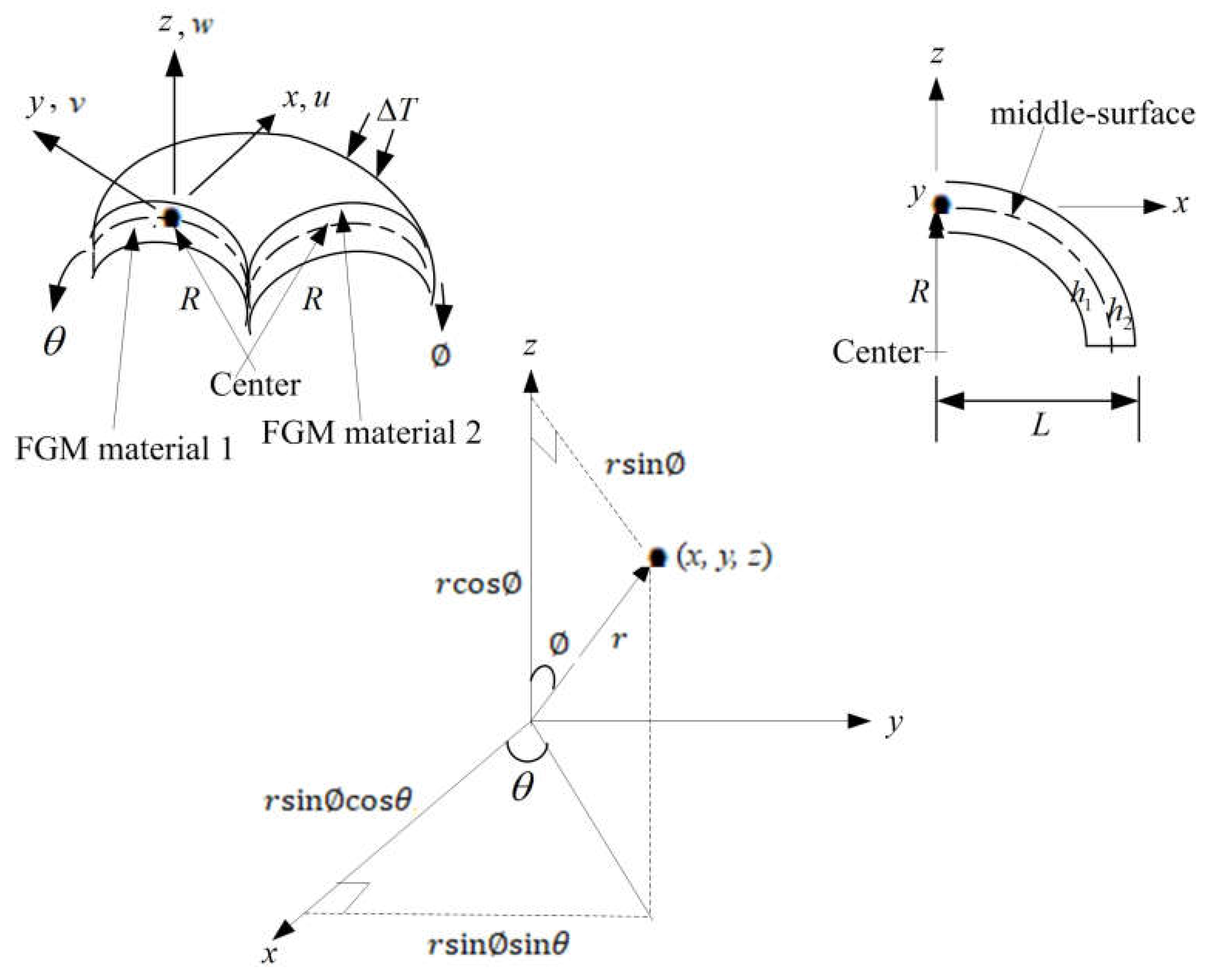
Figure 1. Two-material thick FGM spherical shell for 0° ≦ ∅ ≦ 90° under ∆T.
Computation 13 00245 g001
Figure 2. w ( L / 2 , 2 π / 2 ) (mm) vs. t(s) and σ x (GPa) vs. t(s) at = 45 ° for (a) L / h * = 5, (b) L / h * = 10, (c) L / h * = 5, and (d) L / h * = 10; (e) similarly compared results [23,24] where h = 7 mm; n denotes volume fraction index.
Computation 13 00245 g002aComputation 13 00245 g002bComputation 13 00245 g002c
Figure 3. w ( L / 2 , 2 π / 2 ) (mm) vs. T(K) and σ x (GPa) vs. T(K) at = 45 ° for (a) L / h * = 5, (b) L / h * = 10, (c) L / h * = 5, and (d) L / h * = 10.
Computation 13 00245 g003
Figure 4. w ( L / 2 , 2 π / 2 ) and σ x vs. at L / h * = 5 and 10 for (a) w ( L / 2 , 2 π / 2 ) (mm) vs. (radian) and (b) σ x (GPa) vs. (radian).
Computation 13 00245 g004
Figure 5. Transient responses of w ( L / 2 , 2 π / 2 ) (mm) for L / h * = 10 at = 45 ° for (a) γ = 284314.1/s and 785.3982/s and (b) γ = 15.707963/s and 0.523599/s.
Computation 13 00245 g005
Table 1. Convergence of FGM spherical shells with advanced nonlinear k α .
c 1 (1/mm2) L / h * GDQ Grids w ( L / 2 , 2 π / 2 )   ( mm )   at   t = 6   s   and   = 10 °
N × M R n = 0.5 R n = 1 R n = 2
0.925925107 × 7–0.105900–0.1342110.183353
9 × 9–0.105718–0.1339530.183347
11 × 11–0.105725–0.1339660.183396
13 × 13–0.105720–0.1339750.183327
57 × 70.143114–0.0213530.032313
9 × 90.140667–0.0214010.032365
11 × 110.140681–0.0214010.032373
13 × 130.140711–0.0214000.032354
0107 × 70.010220–0.0004650.011511
9 × 90.010220–0.0004650.011509
11 × 110.010220–0.0004650.011509
13 × 130.010220–0.0004650.011509
57 × 70.0013890.0097980.002504
9 × 90.0013890.0098000.002504
11 × 110.0013890.0098000.002504
13 × 130.0013890.0098000.002504
Table 2. Constituent material properties of FGMs [32].
Constituent
Material
P i P 0 P 1 P 1 P 2 P 3
SUS304 E 1 (Pa)201.04 × 10903.079 × 10−4−6.534 × 10−70
ν 1 0.32620−2.002 × 10−43.797 × 10−70
ρ 1 (Kg/m3)81660000
α 1 (K−1)12.33 × 10−608.086 × 10−400
κ 1 (W/(mK))15.3790000
C v 1 (J/(KgK))496.560−1.151 × 10−31.636 × 10−6−5.863 × 10⁻¹⁰
Si3N4 E 2 (Pa)348.43 × 1090−3.70 × 10−42.16 × 10−7−8.946 × 10⁻¹¹
ν 2 0.240000
ρ 2 (Kg/m3)23700000
α 2 (K−1)5.8723 × 10−609.095 × 10−400
κ 2 (W/(mK))13.7230000
C v 2 (J/(KgK))555.1101.016 × 10−32.92 × 10⁻⁷−1.67 × 10⁻¹⁰
Table 3. Fundamental natural frequency ω 11 for h * = 1.2 mm and = 10 ° .
L / h * R n c 1
(1/mm2)
ω 11 (1/s)
T = 1 KT = 100 K T = 300 K T = 600 K T = 1000 K
50.50.92592500.017753
0.030261
0.019616
0.042820
0.002242
0.017373
0.002483
0.018059
0.003476
0.019515
10.92592500.018323
0.017553
0.015267
0.017667
0.001043
0.032885
0.001225
0.018680
0.034586
0.020544
20.92592500.001478
0.018310
0.005019
0.035069
0.007050
0.018562
0.006940
0.019306
0.022372
0.021639
100.92592500.002686
0.019477
0.002724
0.041641
0.002792
0.019424
0.002914
0.020212
0.003098
0.023438
80.50.92592500.027982
0.068177
0.002177
0.028099
0.001361
0.048065
0.001483
0.029955
0.056226
0.031924
10.92592500.002221
0.028821
0.001572
0.029106
0.000686
0.029721
0.000802
0.030896
0.033925
0.064964
20.92592500.000954
0.030012
0.005579
0.030189
0.007748
0.030672
0.007564
0.074640
0.002882
0.035115
100.92592500.001917
0.031958
0.001944
0.031918
0.001991
0.032147
0.002079
0.033439
0.002210
0.038010
100.50.92592500.002178
0.071210
0.001683
0.033721
0.001090
0.034853
0.001186
0.036169
0.046005
0.061677
10.92592500.001709
0.034198
0.001251
0.034778
0.000556
0.035819
0.000649
0.037175
0.040729
0.038822
20.92592500.000770
0.035435
0.005767
0.035926
0.007701
0.036853
0.007537
0.038253
0.002178
0.040465
100.92592500.001585
0.037492
0.001608
0.037801
0.001647
0.038502
0.001720
0.076383
0.001828
0.043298
Table 4. Four-side simply supported boundary conditions used in the text.
LocationConstraints
x = 0 N x x = M ¯ x x = v 0 = w = ϕ θ = 0
x = L N x x = M ¯ x x = v 0 = w = ϕ θ = 0
x = 0 u 0 x = v 0 = w = ϕ x x = ϕ θ = 0
i = 1 l = 1 N A 1 , l ( 1 ) U l , j = V 1 , j = W 1 , j = l = 1 N A 1 , l ( 1 ) ϕ x l , j = ϕ θ 1 , j = 0
x = L u 0 x = v 0 = w = ϕ x x = ϕ θ = 0
i = N l = 1 N A N , l ( 1 ) U l , j = V N , j = W N , j = l = 1 N A N , l ( 1 ) ϕ x l , j = ϕ θ N , j = 0
θ = 0 N θ θ = M ¯ θ θ = u 0 = w = ϕ x = 0
θ = 2 π N θ θ = M ¯ θ θ = u 0 = w = ϕ x = 0
θ = 0 u 0 = v 0 θ = w = ϕ x = ϕ θ θ = 0
j = 1 U i , 1 = m = 1 M B 1 , m ( 1 ) V i , m = W i , 1 = ϕ x i , 1 = m = 1 M B 1 , m ( 1 ) ϕ θ i , m = 0
θ = 2 π u 0 = v 0 θ = w = ϕ x = ϕ θ θ = 0
j = M U i , M = m = 1 M B M , m ( 1 ) V i , m = W i , M = ϕ x i , m = m = 1 M B M , m ( 1 ) ϕ θ i , m = 0
Table 5. Parameter ranges and their physical rationale used in the analysis.
Parameter ValuesPhysical Rationale
T = 1 K, 100 K, 300 K, 600 K, 1000 Kenvironmental temperature
R n = 0.1, 0.2, 0.5, 1, 2, 5, 10power-law index of FGM
L / h * = 5, 10length-to-thickness ratio
h * = 1.2 mmthickness
c 1 = 0/mm2, 0.925925/mm2coefficient term for TSDT displacement
Disclaimer/Publisher’s Note: The statements, opinions and data contained in all publications are solely those of the individual author(s) and contributor(s) and not of MDPI and/or the editor(s). MDPI and/or the editor(s) disclaim responsibility for any injury to people or property resulting from any ideas, methods, instructions or products referred to in the content.