Article

Numerical Study on Infrared Radiation Signatures of Debris During Projectile Impact Damage Process

College of Mechatronic Engineering, North University of China, Taiyuan 030051, China
*
Author to whom correspondence should be addressed.
Computation 2025, 13(10), 244; https://doi.org/10.3390/computation13100244 (registering DOI)
Submission received: 15 August 2025 / Revised: 30 September 2025 / Accepted: 16 October 2025 / Published: 19 October 2025
(This article belongs to the Section Computational Engineering)

Abstract

High-speed impact is a critical mechanism for structural damage. The infrared signatures generated during fragment formation provide essential data for damage assessment, protective system design, and target identification. This study investigated an aluminum alloy blunt projectile penetrating a target plate by employing smoothed particle hydrodynamics to simulate the debris ejection thermal and infrared properties. The infrared signatures of the debris clouds were calculated using Mie scattering theory under a spherical particle approximation. The reverse Monte Carlo methodology was applied to solve the radiative transfer equations and quantify the infrared emission characteristics. The infrared radiation characteristics of the debris cloud were investigated for projectile impact velocities of 800, 1000, and 1200 m/s. The results showed that the anterior debris regions reached peak temperatures of approximately 1200 K, with a temperature rise of 150–200 K per 200 m/s velocity increase behind the target. The medium-wave (3–5 μm) infrared intensity of the debris cloud was higher than the long-wave (8–12 μm) infrared intensity. The development of debris clouds enhanced the dispersion effect and slowed the increase in infrared radiation intensity in the same time interval. This study provides theoretical foundations for the dynamic infrared radiation characteristics of fragments generated by high-velocity projectile impacts. The infrared radiation characteristics within typical spectral bands can be utilized to assess hit probability and kill effectiveness.

Graphical Abstract

1. Introduction

High-speed-impact processes for projectiles are widely used in military, aerospace, and engineering applications [1,2,3]. When the projectile hits a target and produces a high-speed impact, the large impact force causes fragmentation of the contact part of the metal target. In this process, the kinetic energy of the projectile is partly converted into internal energy of the fragments, which increases the temperature of the target fragments. Typically, high-temperature and high-speed fragments can cause severe damage to the surrounding environment [4]. The radiation characteristics of debris are governed by the principles of transient heat transfer. The conversion of impact kinetic energy into thermal energy dominates the spectral radiance in the 3–14 μm wavelength range [5]. This can be used to assess impact damage and signal characteristics. Therefore, studying the infrared characteristics of projectile-impact debris clouds is of great significance for designing protective materials and identifying targets.
The temporal and spatial distributions of high-speed-impact debris clouds form the basis for studying the infrared characteristics of projectile impact damage fragments. Current research primarily focuses on numerical simulations and experimental observations. The smoothed particle hydrodynamics (SPH) numerical calculation method avoids the problems of grid distortion and grid failure caused by large deformations that often result from impacts [6]. Therefore, the SPH algorithm is widely used in numerical studies of high-speed physical phenomena and projectile penetration [7,8,9]. SPH possesses unique advantages compared to other impact algorithms. For example, Ma et al. [10] employed the SPH method to investigate the distribution of milligram-mass-level debris clouds generated when a hypersonic 93% tungsten alloy projectile struck a steel plate target at 3000 m/s. Wang et al. [11] utilized the SPH method to simulate the penetration process of a long-rod projectile through a layered metal target at velocities of 1000 m/s and 1500 m/s. Additionally, to enhance computational efficiency, fast engineering models for debris cloud simulation [12,13] have been developed based on extensive numerical simulations. However, compared to full-scale numerical simulations, these fast engineering models typically exhibit limitations including restricted physical fidelity, constrained parameter ranges, and inadequate uncertainty quantification.
In experimental investigations of high-speed-impact debris clouds, researchers have employed X-ray photography [14] and high-speed photography [15] to record debris cloud formation and observe spatial distribution characteristics. While these methods provide valuable debris cloud characteristic information from imaging data, certain limitations persist in their diagnostic capabilities. Infrared imaging techniques offer complementary debris cloud characteristic information from alternative viewing perspectives, enabling the characterization of thermal and scattering properties. Current studies of infrared characteristics in high-speed-impact debris clouds have primarily utilized infrared camera observations [16,17,18]. However, due to the high velocities and brief duration of impact processes, infrared cameras must possess extremely high frame rates. Achieving simultaneous high frame rate and high spatial resolution in infrared dynamic detection remains challenging, particularly for medium-wave infrared camera systems. Therefore, numerical calculation methods that characterize the infrared properties of impact processes are necessary to compensate for experimental measurement limitations.
Research on infrared characteristics during high-speed-impact processes can be divided into two parts: 1. Characterization of the high-speed-impact process; 2. Characterization of infrared radiation properties. High-speed-impact processes occur on an extremely short timescale, typically in the microsecond range. During this process, the stress, strain state, and failure mechanisms of materials are difficult to obtain through experimental or theoretical analysis methods. Numerical simulations not only visualize high-speed-impact processes specifically but also efficiently capture variations in various physical quantities during the impact, effectively addressing the high cost associated with experimental measurements. Compared to finite element analysis within the Lagrangian framework, the mesh-free nature of the SPH method avoids mesh deformation and failure issues under large deformation conditions. The SPH algorithm demonstrates exceptional performance in studying high-speed- and ultra-high-speed-impact processes, enabling detailed simulations of post-impact large deformation states. Currently, infrared cameras can capture infrared radiation characteristics during impacts. However, due to impact speeds occurring at microsecond scales and extremely short durations, obtaining high-resolution thermal images at high frame rates is challenging and costly. Numerical simulations, however, are not constrained by these limitations. In characterizing infrared radiation properties, primary radiation transfer calculation methods include ray tracing, Monte Carlo (MC), and reverse Monte Carlo (RMC). For debris clouds, significant scattering occurs among high-temperature fine particles, necessitating its inclusion in radiation transfer calculations. MC-based methods excel in this regard, while RMC methods significantly reduce computational time.
This paper proposes a computational framework based on the coupled SPH+RMC method to investigate the infrared characteristics of the impact damage process of aluminum alloy projectiles at impact velocities ranging from 800 to 1200 m/s. The SPH method is employed to discretize the entire damage environment of the projectile impacting the target plate into a debris cloud. The spatial distribution of temperature within the debris cloud during this process is numerically simulated using LS-DYNA R13 software. The reverse Monte Carlo (RMC) method is then applied to account for absorption and scattering phenomena in infrared radiation transport, calculating the infrared radiation characteristics of the debris cloud. The study focuses on analyzing the influence of impact velocity on the infrared radiation properties of the debris cloud. It can be used to further evaluate hit probability and damage effectiveness from the perspective of infrared radiation.

2. Numerical Calculation Model

2.1. SPH Method

SPH [19,20] is a mesh-free computational method that discretizes a continuum into a set of particles that carry properties such as mass and velocity. The particles collectively adhere to the principles of mass, momentum, and energy conservation although they are discrete. In the SPH method, the approximation of a function f(x) over a domain Ω is first constructed through integral formulation using a kernel function. This integral approximation effectively replaces the function value at a point with the weighted sum of the contributions of the neighboring particles, enabling the numerical solution of fluid dynamics problems without requiring a predefined mesh.
f x f x = Ω f x W x x , h d x
where f x represents an approximation of f(x) and W denotes the kernel function. The kernel function W is a weighting function that determines the influence of neighboring particles on the approximation at any given point. In this study, linear kernel function is defined as:
W x , h = 1 h x d θ x
where d, h, and θ denote the spatial dimensions, smoothing length, and auxiliary function, respectively.
In the SPH method, the solution domain is discretized into a set of particles, each possessing a finite mass and occupying a certain volume in space. Therefore, the obtained continuous integral approximation must be discretized over the particles within the solution domain via particle approximation. By replacing the volume element dx’ in Equation (1) with the particle volume ΔV, the approximate integral of the function f(x) can be expressed as a discretized particle approximation:
f x = j = 1 N f x j W x x , h Δ V j
where ΔVj is the volume of particle j, j = 1, 2, 3, …, N, and N is the total number of particles.
The SPH expressions for the three-dimensional mass conservation equation, momentum conservation equation, and energy conservation equation are as follows:
d ρ i d t = = j = 1 N m j v i j β W i j x i β
d v i α d t = = j = 1 N m j σ i α β ρ i 2 + σ j α β ρ j 2 W i j x i β
d e i d t = = σ i α β j = 1 N m j v i α ρ i 2 + v j α ρ j 2 W i j x i β
where x is the spatial position vector, v is the velocity vector, σ i and σ j denote the stress tensor, superscripts α and β denote spatial coordinate directions, ρ is the density; e is the internal energy, t is time, mj is the mass of particle, and Wij is the smoothing function describing the influence of particle j on particle i.

2.2. Failure Criterion

The most fundamental approach for setting failure criteria involves specifying threshold values for material characteristic parameters to control the material failure behavior [21]. The widely used cumulative damage models include the Johnson–Cook failure model [22], which considers the effects of stress triaxiality, strain rate, and temperature, and the Tuler–Butcher failure model [23], which considers the peak stress and loading duration.
The model proposes the concept of strain accumulation damage based on the concept of void growth [24] and is represented by the following formula:
D = Δ ε p ε f
where D denotes the damage parameter, D = 0 to 1, with D = 0 initially, material failure occurs when D = 1; Δ ε p is the plastic strain increment per time step and ε f is the failure strain at the current time step under the stress state, strain rate, and temperature.
The Johnson–Cook failure model calculates the failure strain ε f of materials by considering the effects of stress triaxiality, strain rate, and temperature according to the relationship is:
ε f = D 1 + D 1 exp D 3 σ 1 + D 4 ln ε ˙ 1 + D 5 T
where D1, D2, D3, D4 and D5 are material constants; σ = p / σ e f f , p is the pressure, σ e f f is the equivalent pressure; ε ˙ * = ε ˙ / ε ˙ 0 is the dimensionless plastic strain rate, where ε ˙ and ε ˙ 0 denote the effective plastic strain rate and the reference plastic strain rate, respectively; and T* = (TTr)/(TmTr) is the dimensionless temperature, where T, Tr and Tm denote absolute temperature, reference temperature, and melting temperature of the material, respectively.

2.3. Calculation of Particle Radiation Property Parameters

Mie theory [25] is the classic calculation model for spectral radiation property parameters of particles. The Mie scattering equation is the far-field solution to Maxwell’s equations when light is projected onto a spherical particle. The calculation is not limited by the particle diameter, and the formulas for the attenuation factor Qe, scattering factor Qs, scattering albedo, and scattering phase function of the spherical particles in the continuous wave band are as follows:
Q e m , χ = 2 χ 2 n = 1 2 n + 1 Re a n + b n
Q s m , χ = 2 χ 2 ± n = 1 2 n + 1 Re a n 2 + b n 2
w p = Q s / Q e
Φ p m , χ , Θ = 1 Q s χ 2 S 1 2 + S 2 2
where m denotes the optical constant of the particle. m = nik, this formula is in complex form, where n and k are the refractive and absorption indices, i denotes the imaginary part. χ , wp, Φ p and Θ denote the scale parameter, reflectivity of a single particle, scattering-phase function of a single particle, and angle between the scattering and incident directions, respectively. Re represents the real part of a complex number; an and bn are the Mie scattering coefficients; S1 and S2 are the complex amplitude functions.
The spectral radiation properties of particle components can be represented by attenuation coefficient, absorption coefficient, and scattering coefficient, specifically expressed as:
τ λ = π 4 D p 2 N p Q e x t , λ κ λ = π 4 D p 2 N p Q a b s , λ ζ λ = π 4 D p 2 N p Q s c a , λ
where Dp denotes particle diameter, Np denotes particle number density.

2.4. Radiation Transmission Method

The temperature field of the high-speed-impact debris cloud can be used as the input to determine the radiation emittance of a single particle according to Planck’s law [26]. Based on the particle radiation emittance and physical radiation parameters, the RMC method was used to solve the radiation transmission problem and obtain the infrared radiation characteristics of the particle cloud.
As a random sampling method, the RMC approach in this study establishes a probabilistic model based on phenomena such as emission, absorption, and scattering during ray transport. It achieves radiative transfer simulation through extensive random sampling. The RMC method traces rays backward from the detector. It first determines the initial position and transmission direction of rays at the detector, then tracks and statistically analyzes the ray transmission process. Random events during transmission (absorption, reflection, scattering) are all handled according to the principle of randomness: If a ray is absorbed, tracking for that ray ceases, and a new ray is emitted for tracking. If reflection occurs, the reflection direction is determined and tracked. If scattering occurs, the scattering direction is determined and tracked until the ray is absorbed. The final step involves counting the number of absorbed rays to determine their contribution to the target’s radiation.
The most critical aspect of the RMC method during computation is establishing the probability model for the transmission process. For the diffuse emission distribution within light rays, this can be derived from Lambert’s law. The zenith angle of the emission direction (the angle between the surface normal at the emission point and the emission direction) and the azimuthal angle are determined by the following equations:
θ = arccos 1 R θ ψ = 2 π R ψ
where R θ and R ψ are uniformly distributed random numbers for the zenith angle and the circumferential angle, respectively. During transmission, radiation undergoes attenuation when passing through a medium. This attenuation process can be characterized by the maximum possible transmission length of the light, as shown in the following equation:
s k = 1 τ k ln 1 R s
where Rs denotes uniformly distributed random numbers, and τ k denotes the spectral band attenuation coefficient. When light interacts with particles, it may be absorbed or scattered by them. This can be determined through the particle albedo, which is expressed by the following equation:
w = ζ s , p / τ p
where ζ s , p and τ p represent the scattering coefficient and attenuation coefficient of the particle, respectively. A random number Rw is generated. If Rw > w, the beam is absorbed by the particle, recorded, and its tracking is terminated; otherwise, the beam is scattered by the particle. The results are statistically calculated using a weighted average method. When a pixel point pi emits m rays and the number j of absorbed rays is counted, the radiation value obtained at pixel point pi is:
I p i = I j M
The specific steps are as follows. First, considering the detector parameters (including detector position and pixel count), random sampling parameters (including random ray emission position, direction, and ray count), and particle spatial position parameters (including the particle’s x, y, and z coordinates in space) as input, the photon starting from the detector and entering the particle field is simulated. Second, we determine whether the photon intersects with the particle. Intersections are categorized into three types. (1) If there is an intersection effect, we determine whether absorption or scattering occurs based on the albedo. (2) If absorption occurs, the light is recorded and re-emitted. (3) If scattering occurs, the scattering direction is randomly generated based on the scattering angle generated during the calculation of the physical parameters of the particle. Light propagation continues until absorption occurs. Finally, the locations of photons emitted in the radiation transmission module are counted, and the absorbed photons are included in the contributions to the radiation calculation. The weighted average method is used to perform statistical calculations to obtain the infrared radiation results. The radiation transmission process is illustrated in Figure 1.

3. Calculation Conditions

3.1. Geometry Model and Boundary Settings

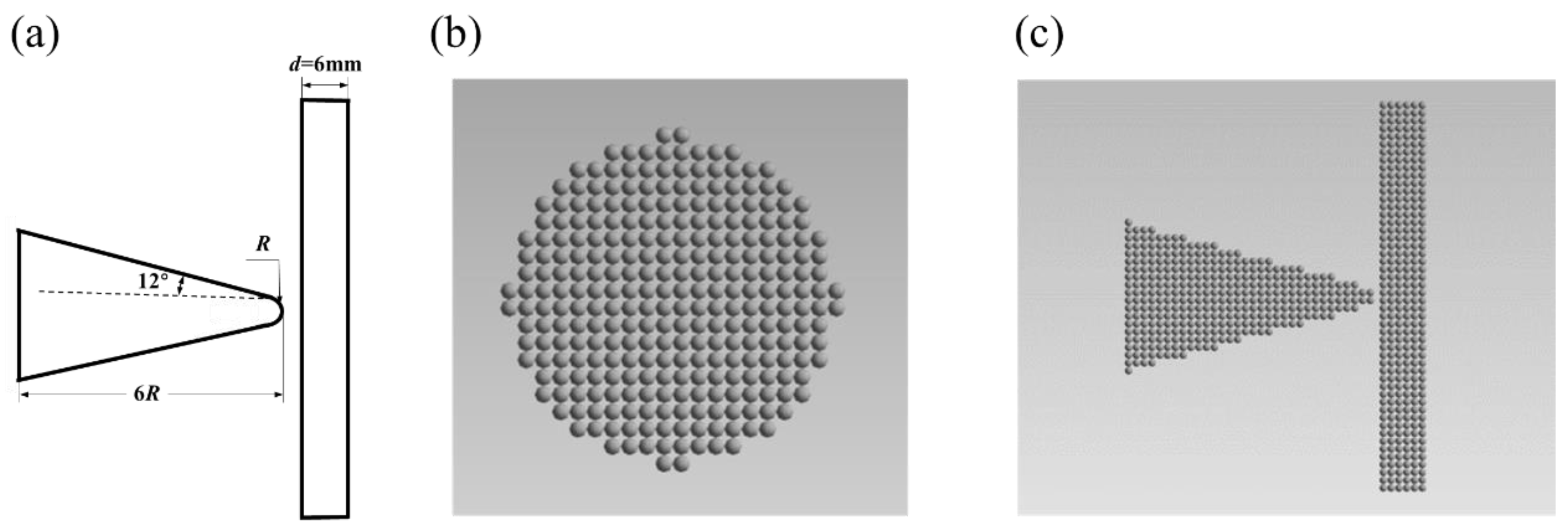
A blunt conical projectile was used in the calculation model used in this study. The nose radius of the blunt conical projectile was R = 2.5 mm. The semi-cone angle of the cone and cone length were α = 12° and L = 6R = 15 mm, respectively. The target plate was square, with side length and thickness of 60 mm and d = 6 mm, respectively. During the impact process, the axis of the blunt cone passed through the center of the target plate. The geometric dimensions of the blunt cone and target plate are shown in Figure 2a.
Since SPH particles inherently possess certain physical and geometric properties, the following rules must be followed when constructing SPH models in LS-DYNA: SPH particles within the model should be as regular and uniform as possible, and their masses should be as consistent as possible. For projectiles with blunt-nosed shapes, the uniformity of SPH particle generation significantly impacts computational results. The SPH modeling in this paper employs spherical particles with uniformly set diameters and equidistant division to ensure consistent particle mass. Approximately 60,000 SPH particles were utilized during modeling. The particle generation process is illustrated in Figure 2b,c. Figure 2b shows the SPH particle structure at the bottom of the projectile, revealing a uniform particle distribution where each particle occupies a nearly identical mass and spatial volume. In the calculation, the target plate was set to nonreflective boundary conditions to eliminate the reflection effect of stress waves propagating inside the target plate during the impact. Fixed boundary conditions were applied outside the target plate to limit its overall displacement during a high-speed impact. An initial velocity, which was also the target impact velocity, was applied to the blunt cone. The initial temperatures of the blunt body and target plate were both 293 K. In LS-DYNA, the Johnson–Cook failure model was employed as the failure criterion and the auxiliary functions are defined using cubic B-spline curves.

3.2. Material Parameters

In this study, the blunt projectile and target plate were composed of aluminum alloy. The material parameters originate from the modified Johnson–Cook constitutive model parameters for 6061-T651 aluminum alloy, obtained from Hopkinson bar and Taylor bar tests published in Reference [27]. The specific parameters are listed in Table 1.

3.3. Calculation Condition Design

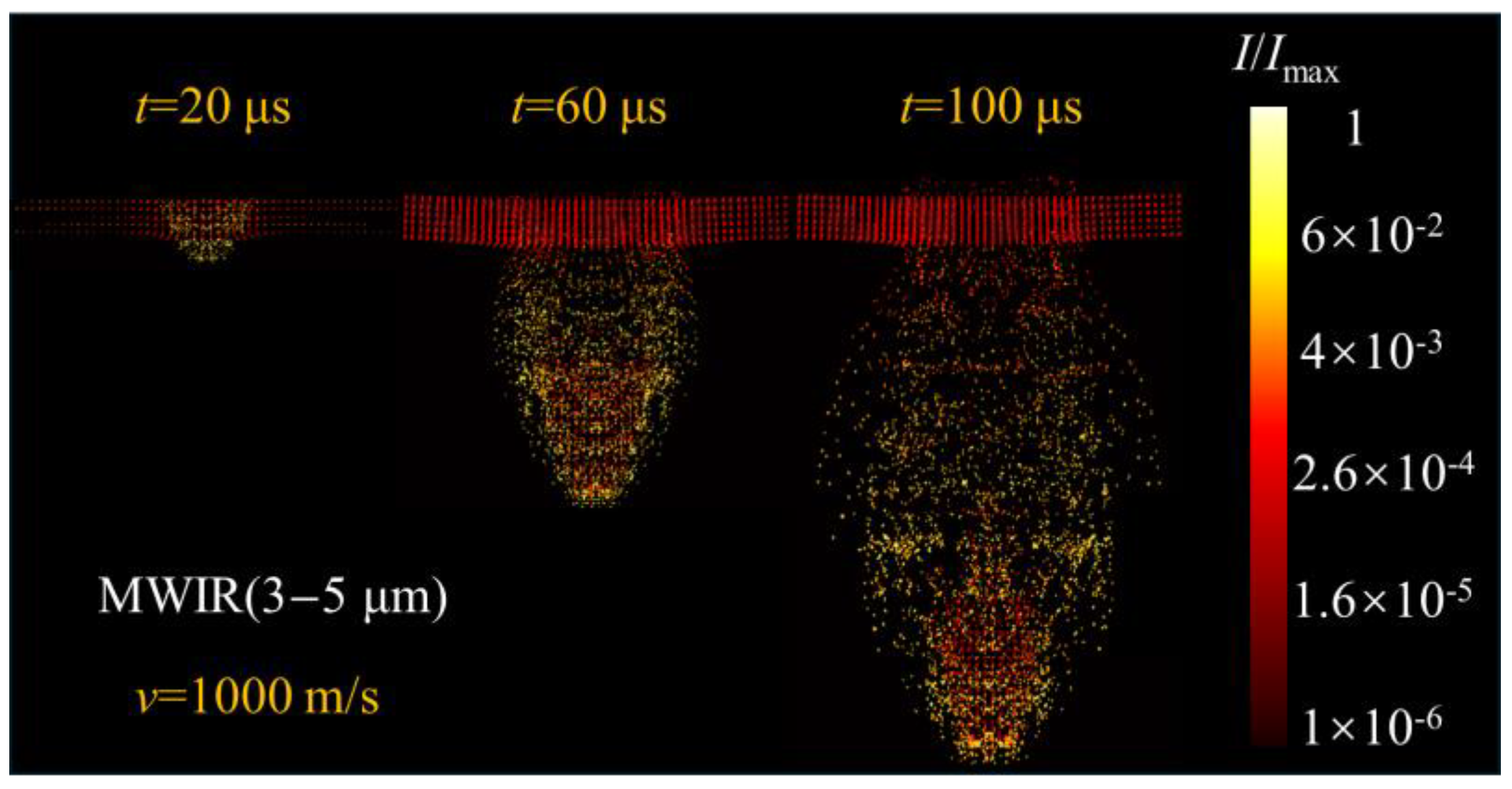
We assumed that the projectile axis was perpendicular to the contact surface of the target plate and that the angle of attack of the projectile flight was zero. Three target impact speeds were used in this study—U = 800, 1000, and 1200 m/s—referencing the velocity of standard small armor-piercing rounds when penetrating vertical target plates. Projectile impact is a dynamic process, which requires time in the range of several hundred milliseconds. Only four representative moments were selected for analysis in this paper, namely, t = 20 μs, 60 μs, 80 μs, and 100 μs. In the infrared calculation process, only the observation direction perpendicular to the flight speed of the projectile was considered. The two observation bands were the medium-wave infrared (MWIR) band of 3–5 μm and long-wave infrared (LWIR) band of 8–12 μm.

4. Results and Analysis

4.1. Temperature Distribution of Debris Cloud

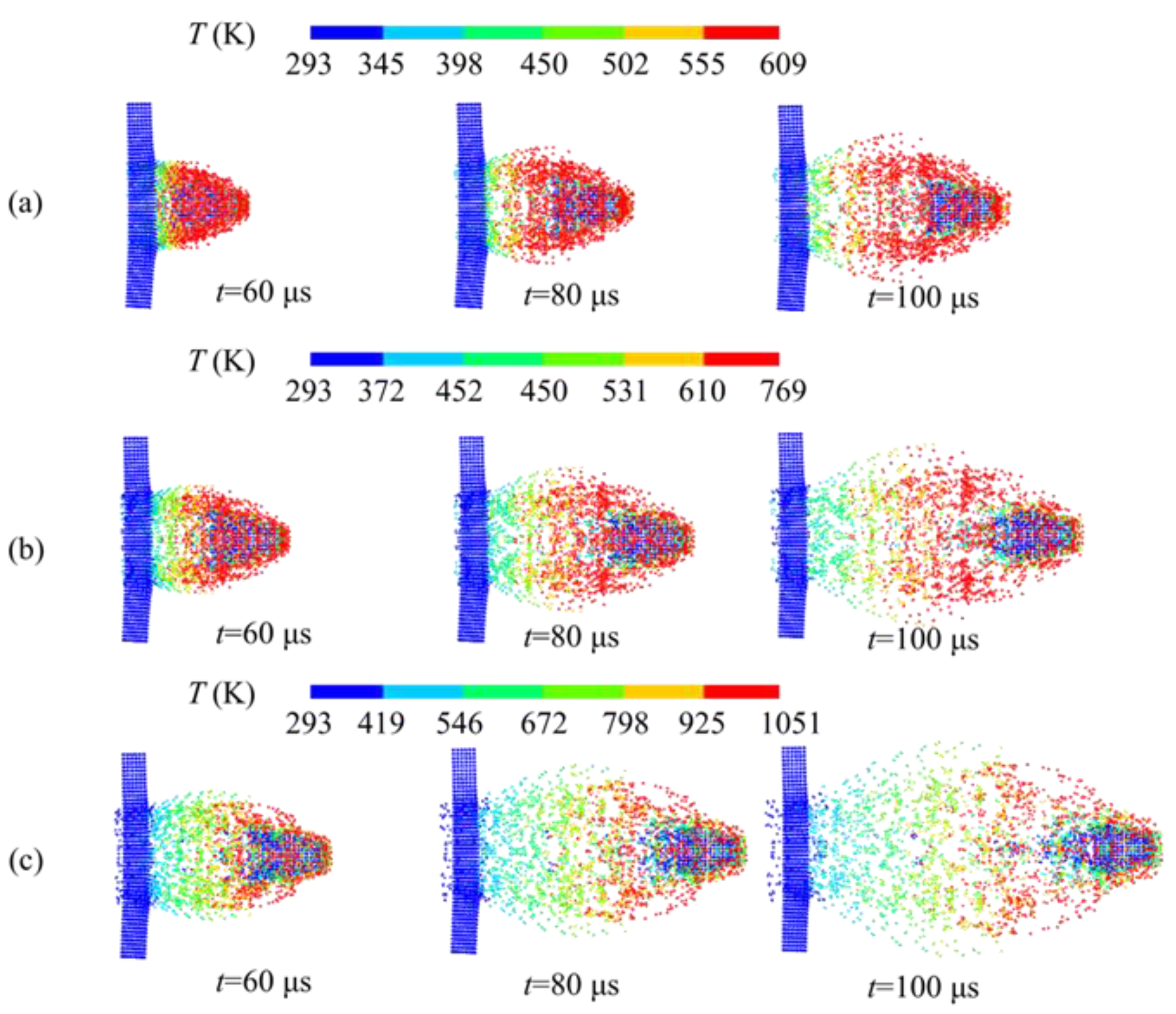
The temperature distribution of the debris cloud behind the target plate is a basic parameter for studying the infrared radiation characteristics of the projectile impact damage process. It indicates the transient temperature distribution of the debris cloud in space after projectile impact. Figure 3a, Figure 3b, and Figure 3c show the temperature cloud diagrams of the debris cloud at three representative moments at target impact speeds of 800 m/s, 1000 m/s, and 1200 m/s, respectively. The figure shows that when the projectile penetrates the target plate, the area where the projectile and target plate are in direct contact exhibits a significant temperature increase behind the target. The high-temperature areas are concentrated at the head of the debris cloud and periphery of the debris cloud. The temperature increase results from kinetic energy conversion through plastic deformation, frictional heating, and shock wave compression. High strain rates create adiabatic conditions where heat generation exceeds conduction, localizing temperature rise at the impact zone and explaining the concentrated heating at the fragment cloud’s leading edge and periphery.
The parts that do not make contact with the target plate do not directly undergo the impact and contact friction processes, and the low heat transfer in a short time results in a low temperature. In a short period, the high-temperature area of the debris cloud accumulates. The high-temperature region within the debris cloud continues to expand due to its own heat and kinetic energy. The high-temperature debris cloud advances forward continuously, while the high-temperature sections at the tail and periphery of the cloud also merge with the central region. This process causes the overall high-temperature zone to expand continuously. The maximum temperature of the debris cloud increases with the impact speed, and the temperature of the debris cloud typically increases by 150–200 K when the impact speed increases by 200 m/s.

4.2. Effect of Target Impact Speed on Infrared Radiation

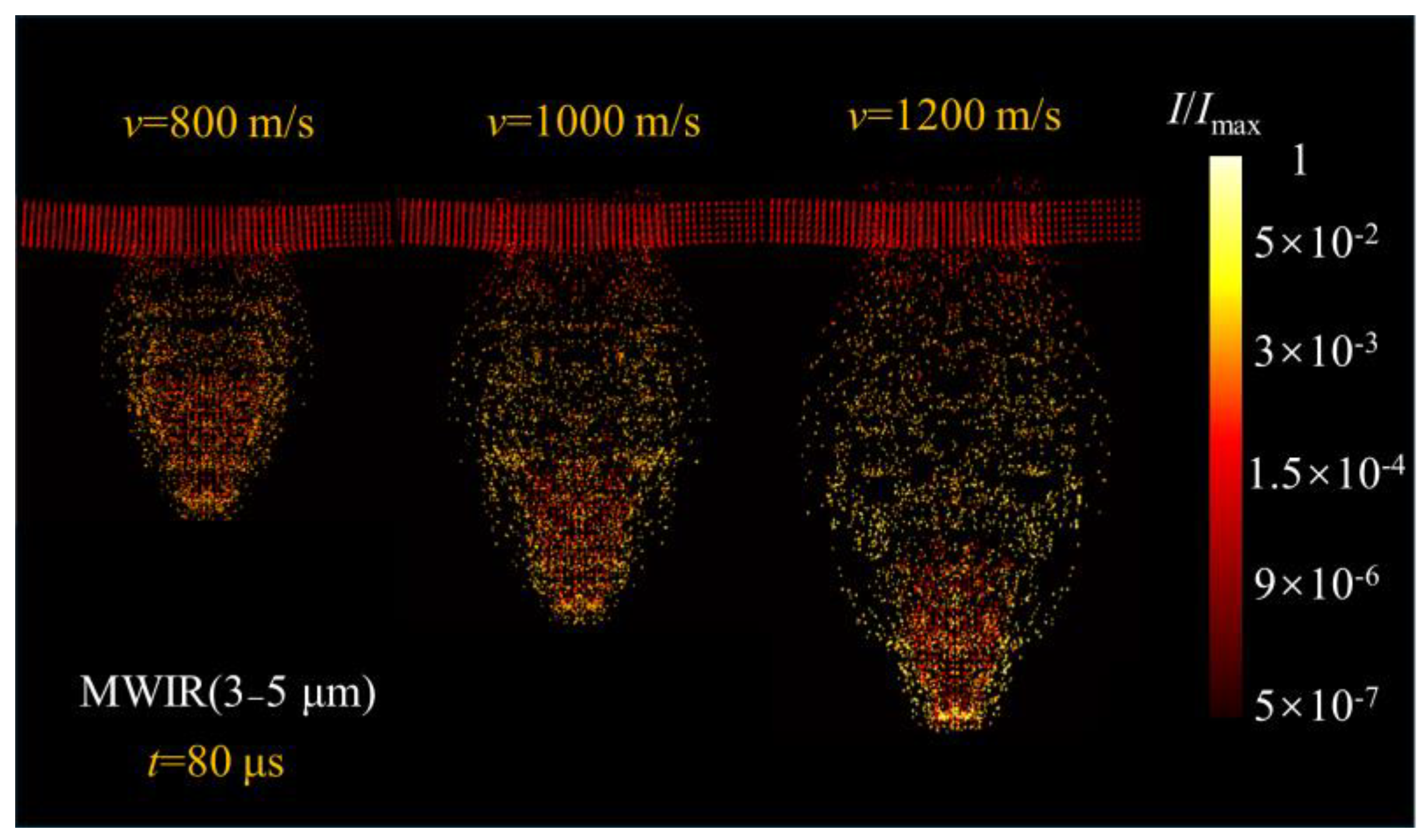
The projectile impact velocity affects the morphology and thermal characteristics of damage debris clouds because the impact process converts kinetic energy into internal energy. Thus, the impact velocity of the projectile when penetrating the target plate affects the infrared radiation characteristics behind the target. Figure 4 shows the infrared radiation distribution diagram for the impact velocities of 800 m/s, 1000 m/s, and 1200 m/s. The radiation intensity was regularized using the maximum radiation intensity. As seen in Figure 4, the radiation intensity of the debris behind the target is the highest in the medium-wave band, indicating that the medium-wave band is the best for observing the debris behind the target.
The radiation intensity distribution shows that at the same time (t = 80 μs), the scale of the debris radiation intensity distribution under different impact velocities differ considerably. Higher impact velocities correspond to a larger spatial scale of the debris cloud behind the target and a stronger dispersion effect of the debris cloud. The area of high radiation intensity and the radiation intensity at the front of the debris cloud increased with the impact velocity.
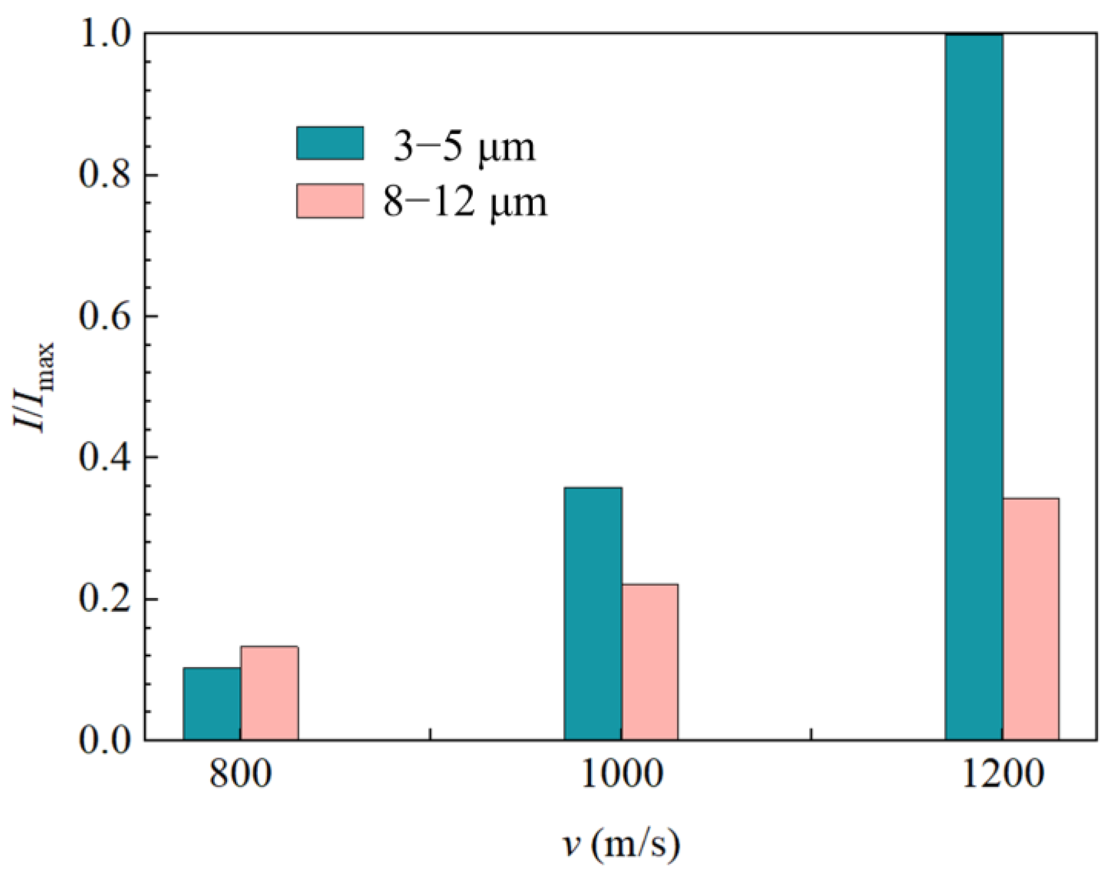
Figure 5 shows the integrated intensity of the debris cloud in MWIR (3–5 μm) and LWIR (8–12 μm) at t = 80 μs when projectile strikes the target plate at velocities of 800 m/s, 1000 m/s, and 1200 m/s. The maximum value of the integrated intensity was used for dimensionless conversion. The integrated intensity of the debris clouds in MWIR is lower than that in the long-wave band when the projectile impacts the target at 800 m/s. However, the MWIR integrated intensity exceeds the LWIR integrated intensity by 50% when the projectile impacts the target at 1000 m/s. Furthermore, at an impact velocity of 1200 m/s, the MWIR integrated intensity is nearly twice that of the LWIR integrated intensity. This occurs because as the impact velocity increases, the temperature level of the debris clouds rises from 500 K to 1000 K, and the high-temperature region also expands. This occurs because the elevated fragment temperatures increase radiation intensity, shifting the peak radiation intensity toward shorter wavelengths in accordance with the Wien displacement law [28]. Consequently, the integrated intensity in the MWIR (3–5 μm) increases and surpasses that in the LWIR (8–12 μm).

4.3. Dynamic Effects of Infrared Radiation from Debris Clouds

Projectile impact damage is a transient process. After the projectile eroded the target plate, the fragments diffused over time. Figure 6 presents the radiation distribution of the debris cloud at different time points, normalized using the maximum radiation intensity, with observations taken in the MWIR (3–5 μm). The figure reveals that at 20 μs, the projectile had not yet fully penetrated the target plate, while at 40 μs, it had largely penetrated the target plate. The debris cloud resembles the projectile’s shape. From the first two time points, it is evident that the high-temperature fragments envelop the projectile and extend forward. After penetrating the target plate, they disperse outward. Over time, regions of high radiation intensity appear not only at the leading edge of the debris cloud but also in its central region. This occurs because the projectile tip makes initial contact with the target plate, causing relatively higher temperatures at the debris cloud’s front edge. As the projectile continues to contact the target plate, temperatures steadily rise. The high-temperature zone in the central region forms due to the blunt shape of the projectile, which causes uneven contact time with the target plate. This creates differences in velocity and time, ultimately raising the temperature in the middle of the debris cloud. Higher temperatures result in greater radiation intensity.
Figure 7 shows the MWIR (3–5 μm) and LWIR (8–12 μm) radiative integral intensities of the debris cloud at different time points when the projectile impacts the target at 1000 m/s. The integral intensities are normalized using their maximum values. The figure reveals that the spectral band integral intensities of the post-impact debris cloud increase over time at a consistent rate. This uniform growth stems from the uniform time intervals, indicating a relatively regular evolution of the debris cloud over time. After the projectile fully penetrates the target plate, the MWIR (3–5 μm) integrated intensity exceeds that of LWIR (8–12 μm). It can be inferred that the higher the projectile velocity, the more pronounced the difference becomes between the integrated radiation intensity in the mid-wave region and that in the long-wave region for the debris cloud formed by the penetration.

5. Conclusions

In this study, an infrared calculation model of the debris cloud of a projectile impacting a target plate was developed based on SPH/RMC. The temperature field and infrared radiation characteristics of the debris cloud of an aluminum alloy blunt projectile impacting a target plate were numerically analyzed, and the influence of the impact velocity on the infrared radiation of the debris and the infrared characteristics of the debris at different times were examined. The main conclusions are summarized below.
(1)
The impact velocity significantly influenced the temperature of the debris cloud. The fragment dispersion effect strengthened and the temperature increased with the impact velocities of the projectile. The temperature of the debris cloud increased by 150–200 K when the impact velocity increased by 200 m/s.
(2)
The MWIR (3–5 μm) infrared radiation intensity of the debris cloud exceeded that of the LWIR (8–12 μm) band, indicating that the MWIR (3–5 μm) was the best band for the detector.
(3)
The increase in the impact velocity enhanced the infrared radiation intensity of the debris cloud. The integrated intensity of the debris cloud at the impact velocity of 1200 m/s was nearly twice that at 1000 m/s.

Author Contributions

Conceptualization, W.G.; Formal analysis, W.G.; Investigation, W.G., T.Z. and Q.N.; Resources, Q.N.; Data curation, T.Z.; Writing—original draft, W.G.; Writing—review and editing, Q.N. All authors have read and agreed to the published version of the manuscript.

Funding

This research was funded by the National Natural Science Foundation of China (52006203, U22B2045) and Fundamental Research Program of Shanxi Province (202403021211078).

Data Availability Statement

The original contributions presented in the study are included in the article, further inquiries can be directed to the corresponding authors.

Conflicts of Interest

The authors declare no conflicts of interest.

Abbreviations

The following abbreviations are used in this manuscript:
SPHSmoothed particle hydrodynamics
RMCReverse Monte Carlo
MWIRMedium-wave infrared
LWIRLong-wave infrared

References

  1. Johnston, J.P.; Pereira, J.M.; Ruggeri, C.R.; Roberts, G.D. High speed thermal imaging on ballistic impact of triaxially braided composites. In Proceedings of the Annual Technical Conference of the American Society for Composites (ASC), West Lafayette, IN, USA, 23–25 October 2017. GRC-E-DAA-TN42986. [Google Scholar]
  2. Alesbrook, L.S.; Burchell, M.J.; Cornwell, L.T.; Corsaro, R.D.; Giovane, F.; Liou, J.C.; Tandy, J.; Wozniakiewicz, P.J. Hypervelocity impact induced light flash experiments on single and dual layer Kapton targets to develop a time of flight space dust and debris detector. Int. J. Impact Eng. 2024, 187, 104897. [Google Scholar] [CrossRef]
  3. Borges, M.C.S.R. Analytical methods for high speed impact behaviour of long rods. Master’s Thesis, Universidade de Lisboa, Lisaboa, Portugal, November 2019; 164p. [Google Scholar]
  4. Ma, K.; Chen, C.L.; Feng, N.; Yin, L.X.; Li, M.R.; Zhou, G. Characteristics of perforation and fragment group expansion of steel sheet impacted by cylindrical 93 tungsten projectile at hypervelocity. Acta Armamentarii 2021, 42, 2350–2359. [Google Scholar]
  5. Vollmer, M.; Möllmann, K.P. Infrared Thermal Imaging: Fundamentals, Research and Applications, 2nd ed.; John Wiley & Sons: Weinheim, Germany, 2018. [Google Scholar]
  6. Liu, G.R.; Liu, M.B. Smoothed Particle Hydrodynamics: A Meshfree Particle Method; World Scientific: Singapore, 2003. [Google Scholar]
  7. Aktay, L.; Johnson, A.F. FEM/SPH coupling technique for high velocity impact simulations. Adv. Mech. Eng. 2007, 5, 147–167. [Google Scholar]
  8. Zhang, X.; Guanghui, J.; Huang, H. Fragment identification and statistics method of hypervelocity impact SPH simulation. Chin. J. Aeronaut. 2011, 24, 18–24. [Google Scholar] [CrossRef]
  9. Lind, S.J.; Rogers, B.D.; Stansby, P.K. Review of smoothed particle hydrodynamics: Towards converged Lagrangian flow modelling. Proc. R. Soc. A. 2020, 476, 20190801. [Google Scholar] [CrossRef] [PubMed]
  10. Ma, K.; Li, M.R.; Chen, C.L.; Feng, N.; Zhao, N.; Ke, M.; Zhou, G. Simulation analysis of distribution of fragments of hypervelocity 93w projectile impacting on a steel plate target. Acta Armamentarii 2019, 40, 2022–2031. [Google Scholar]
  11. Wang, J.T.; Yu, W.L.; Wang, T.; Luo, Y.F.; Wang, S.L. Smoothed particle hydrodynamics algorithm applied in numerical simulation of layered metal targets impacted by long rod projectile. Combust. Explos. Shock Waves 2011, 31, 533–539. [Google Scholar]
  12. Huang, J.; Ma, Z.X.; Ren, L.S.; Li, Y.; Zhou, Z.X.; Liu, S. A new engineering model of debris cloud produced by hypervelocity impact. Int. J. Impact Eng. 2013, 56, 32–39. [Google Scholar] [CrossRef]
  13. Zhang, Y.Q.; Guan, G.S.; Zhang, W.; Pang, B.J. Characteristics of debris cloud produced by normal impact of spherical projectile on thin plate shield. Explos. Shock Waves 2007, 27, 546–552. [Google Scholar]
  14. Piekutowski, A.J. Debris clouds produced by the hypervelocity impact of nonspherical projectiles. Int. J. Impact Eng. 2001, 26, 613–624. [Google Scholar] [CrossRef]
  15. Wang, L.Y.; Jiang, W.J.; Li, M.; Ma, Y.Y. Experimental research on energy release behavior of W/Zr/Hf alloy fragment. Acta Armamentarii. 2019, 40, 1603–1610. [Google Scholar]
  16. Mihaly, J.M. Investigation of Hypervelocity Impact Phenomena Using Real-Time Concurrent Diagnostics. Ph.D. Thesis, California Institute of Technology, Pasadena, CA, USA, 21 May 2013. [Google Scholar]
  17. Meola, C.; Boccardi, S.; Boffa, N.D.; Ricci, F.; Simeoli, G.; Russo, P.; Carlomagno, G.M. New perspectives on impact damaging of thermoset-and thermoplastic-matrix composites from thermographic images. Compos. Struct. 2016, 152, 746–754. [Google Scholar] [CrossRef]
  18. Cai, Y.; Feng, X.; He, C.; Zhang, S.; Li, S.; Liu, J. A 7.62 mm energetic bullet filled with PTFE-Mg-based reactive materials for anti-drone application. J. Mater. Res. Technol. 2024, 30, 8749–8759. [Google Scholar] [CrossRef]
  19. Monaghan, J.J. Shock simulation by the particle method SPH. J. Comput. Phys. 1983, 52, 374–389. [Google Scholar] [CrossRef]
  20. Benz, W. Smooth particle hydrodynamics: A review. In The Numerical Modelling of Nonlinear Stellar Pulsations: Problems and prospects. 1st Eds.; Buchler, J.R., Ed.; NATO ASI Series; Springer: Dordrecht, The Netherlands, 1990; pp. 269–288. [Google Scholar]
  21. Chen, G.; Chen, F.Z.; Xu, W.F.; Chen, Y.M.; Huang, X.C. Investigation on the J-C ductile fracture parameters of 45 steel. Combust. Explos. Shock Waves. 2007, 27, 131–135. [Google Scholar]
  22. Johnson, G.R.; Cook, W.H. Fracture characteristics of three metals subjected to various strains, strain rates, temperatures and pressures. Eng. Fract. Mech. 1985, 21, 31–48. [Google Scholar] [CrossRef]
  23. Tuler, F.R.; Butcher, B.M. A criterion for the time dependence of dynamic fracture. Int. J. Fract. 1984, 26, 322–328. [Google Scholar] [CrossRef]
  24. Rice, J.R.; Tracey, D.M. On the ductile enlargement of voids in triaxial stress fields. J. Mech. Phys. Solids 1969, 17, 201–217. [Google Scholar] [CrossRef]
  25. Bohren, C.F.; Huffman, D.R. Absorption and Scattering of Light by Small Particles; Wiley-VCH Verlag GmbH & Co KGaA: Weinheim, Germany, 1998. [Google Scholar]
  26. Planck, M. On the law of distribution of energy in the normal spectrum. Ann. Der Physic. 1901, 4, 553. [Google Scholar] [CrossRef]
  27. Deng, Y.F.; Zhang, Y.; Wu, H.P.; Zeng, X.Z. Dynamic mechanical properties and modification of J-C constitutive model of 6061-T651 aluminum alloy. J. Mech. Eng. 2020, 56, 74–81. [Google Scholar]
  28. Modest, M.F.; Mazumder, S. Radiative Heat Transfer, 4th ed.; Academic Press: Cambridge, UK, 2021. [Google Scholar]
Figure 1. Flowchart of infrared radiation transfer calculation.
Computation 13 00244 g001
Figure 2. Model geometry and discretization: (a) Model geometry, (b) particle distributions at the bottom of the projectile, and (c) lateral SPH particle distribution of the projectile and target plate.
Computation 13 00244 g002
Figure 3. Temperature distribution of the debris cloud when projectile strikes the target plate at different velocities. (a) velocity = 800 m/s; (b) velocity = 1000 m/s; (c) velocity = 1200 m/s.
Computation 13 00244 g003
Figure 4. IR (3–5 μm) radiation intensity contour of the debris cloud at t = 80 μs when projectile strikes the target plate at velocities of 800 m/s, 1000 m/s, and 1200 m/s.
Computation 13 00244 g004
Figure 5. MWIR (3–5 μm) and LWIR (8–12 μm) integrated intensity of the debris cloud at t = 80 μs when projectile strikes the target plate at velocities of 800 m/s, 1000 m/s, and 1200 m/s.
Computation 13 00244 g005
Figure 6. MWIR (3–5 μm) radiation intensity contour of the debris cloud at t = 20 μs, 60 μs and 100 μs when the projectile impacts the target at a velocity of 1000 m/s.
Computation 13 00244 g006
Figure 7. MWIR (3–5 μm) and LWIR (8–12 μm) integrated intensity of the debris cloud at t = 20 μs, 60 μs, and 100 μs when the projectile impacts the target at a velocity of 1000 m/s.
Computation 13 00244 g007
Table 1. Material parameters of 6061-T651 aluminum alloy [27].
Elasticity Modulus
(GPa)
Poisson’s ratioYield
strength
(MPa)
Hardening coefficient B (MPa)Hardening index nDensity
(kg/m3)
Hardening
coefficient Q (MPa)
Hardening index b
64.00.33278.2245.20.817270058.39.16
Modification factorStrain rate sensitivity coefficientReference
strain rate
(1/s)
Specific heat capacity (J/kg/K)Temperature softening
coefficient
Temperature
softening
index
Reference
temperature
(K)
Melting
temperature
(K)
0.10.02561.33 × 1038902.7452.387294925
Disclaimer/Publisher’s Note: The statements, opinions and data contained in all publications are solely those of the individual author(s) and contributor(s) and not of MDPI and/or the editor(s). MDPI and/or the editor(s) disclaim responsibility for any injury to people or property resulting from any ideas, methods, instructions or products referred to in the content.