1. Introduction
The aim of this study is to find appropriate criteria for the shape optimization of ventilation elements used in protective clothing through metamodeling and a numerical approach. Metamodels, which are also called approximations, response surfaces, or surrogate models, are used to speed up the optimization process [
1]. This is because the solving methods for complex models often contain computationally intensive algorithms. The Efficient Global Optimization [
2,
3] technique, which is primarily based on Kriging, is currently widely used to solve deterministic optimization problems that involve such complex models [
4,
5]. Kriging or Gaussian Process Regression has gained attention as a metamodeling tool for computationally expensive simulations because it provides surfaces with variable complexity (possibly interpolative) within a probabilistic framework [
6].
Thermal comfort is crucial for humans in hot weather or under heavy work load conditions in order to reduce heat stress. Heat stress can cause tedium and tiredness in the mind and body, resulting in personal health problems and a reduction in work productivity [
7,
8]. In recent years, the development of personal cooling garments has received increased attention due to the rapid growth of innovative and functional textiles, the global demand for energy-saving solutions, and the investigation of numerous new materials, cooling strategies, and device structural optimizations. There are different ventilation techniques like electric cooling, liquid cooling, and air cooling with and without an external power source [
9], but our study is based on those without an external power source and by attaching ventilation elements to protective clothing [
10]. The shape of the ventilation element employed has a large impact on the efficiency of air exchange between the exterior environment and the inner clothing microclimate. We reached this conclusion in our previous research study using various shapes of ventilation elements [
10]. We successfully obtained an efficient shape for the ventilation element and further optimized its design based on the criteria of minimum pressure difference in the following study [
11]. In this study, we extend our work by selecting different relevant criteria to achieve appropriate criteria for optimizing a ventilation element and checking the reliability of the process. In this work, the software KEDRO [
12] is used for the shape optimization of the ventilation element, which enables the planning of experiments, the creation of metamodels, and the use of these metamodels for global optimization. SolidWorks is used for the creation of geometrical models based on the design of experiments, and its flow simulation tool is employed to calculate the values of necessary criteria.
Utilizing Computational Fluid Dynamics (CFD) simulation is highly significant in the modeling of reactive flows due to its ability to forecast and analyze intricate fluid dynamics and chemical reactions within a defined and cost-effective environment [
13]. CFD simulation results are derived by employing numerical methods to solve the governing equations of fluid flow using either a finite difference or a finite volume method. The results in the current study were obtained using the finite volume method. In the CFD simulations, the fluid domain is divided into a grid or mesh of discrete cells, and then the governing equations of fluid flow and heat transfer are solved at each of these grid points or cells [
14]. These equations are derived from the fundamental principles of physics, including the conservation of mass, conservation of linear momentum (Newton’s second law), and conservation of energy (the first law of thermodynamics). A single-phase fluid (gas or liquid) is viewed as a continuum when it undergoes motion. The final result of this analysis would be the identification of the three primary unknown variables in fluid dynamics: (1). Velocity vector (∇), (2). Pressure (p), and (3). Temperature (T). In the process of solving the governing equations, four additional quantities are calculated: (1). Density (ρ), (2). Enthalpy (h) or internal energy (e), (3). Viscosity (μ), and (4). Thermal conductivity (k). CFD codes are typically developed for only one of the two flows, compressible (conserved) and incompressible (non-conserved), due to the fact that the governing equation for each flow consists of distinct mathematical quantities [
15]. The study fluid in the present investigation is air, which is compressible. The governing equations for compressible fluid flow are given as follows:
The Continuity Equation:
= time rate change of volume of moving fluid element per unit volume [
16].
Consider a moving element; the mass δm of this element is fixed, and the volume is termed ∂v.
According to the principle of conservation of mass, we can conclude that the rate of change of mass over time is zero when the element moves parallel to the flow [
16].
Navier–Stokes Equations (Momentum Equation):
For
z component
where
,
, and
denote the
x,
y, and
z components of velocity, respectively.
The symbol τ represents the deviatoric stress tensor.
The Energy Equation:
For internal energy (
e):
Here,
is the volumetric rate of heat addition per unit mass, and
indicates heat conductivity.
2. Model Components and Boundary Conditions
The goal of the current study is to identify appropriate criteria for optimizing the geometric design of the ventilation element. The geometrical dimensions of the element with lower and upper bounds of design variables are shown in
Figure 1 and
Figure 2.
The length of lines R60 and R90, which are at 60° and 90°, respectively, with the horizontal axis, are introduced as design variables (shown in
Figure 1 and
Figure 2), with the upper and lower bound limits: (1) 0.36 ≤ R60 ≤ 2; (2) 0.01 ≤ R90 ≤ 2.5. The bottom end points of these lines are control points for NURBS [
17] that define the smooth shape of the outer ring of the ventilation element. The MSDLH design of the experiment is employed to construct the metamodel, considering two factors (shown in
Figure 3). All the dimensions shown in
Figure 1,
Figure 2,
Figure 3 and
Figure 4 are in millimeters.
Figure 1 and
Figure 2 show the smallest and largest dimensions of the element ring, respectively.
Figure 3 shows the generated Design of Experiment (DOE) with 12 numerical values within the given range, where X1 = R60 and X2 = R90 are the coordinates of the element ring. Twelve geometric designs of elements are constructed from the data obtained in KEDRO and then imported into SolidWorks to create geometric models of ventilation elements.
Figure 3a illustrates the 12 different values of an element’s geometry, which determines the shape of the element.
Figure 3b depicts the 12 distinct geometric models of the element that are created using these values.
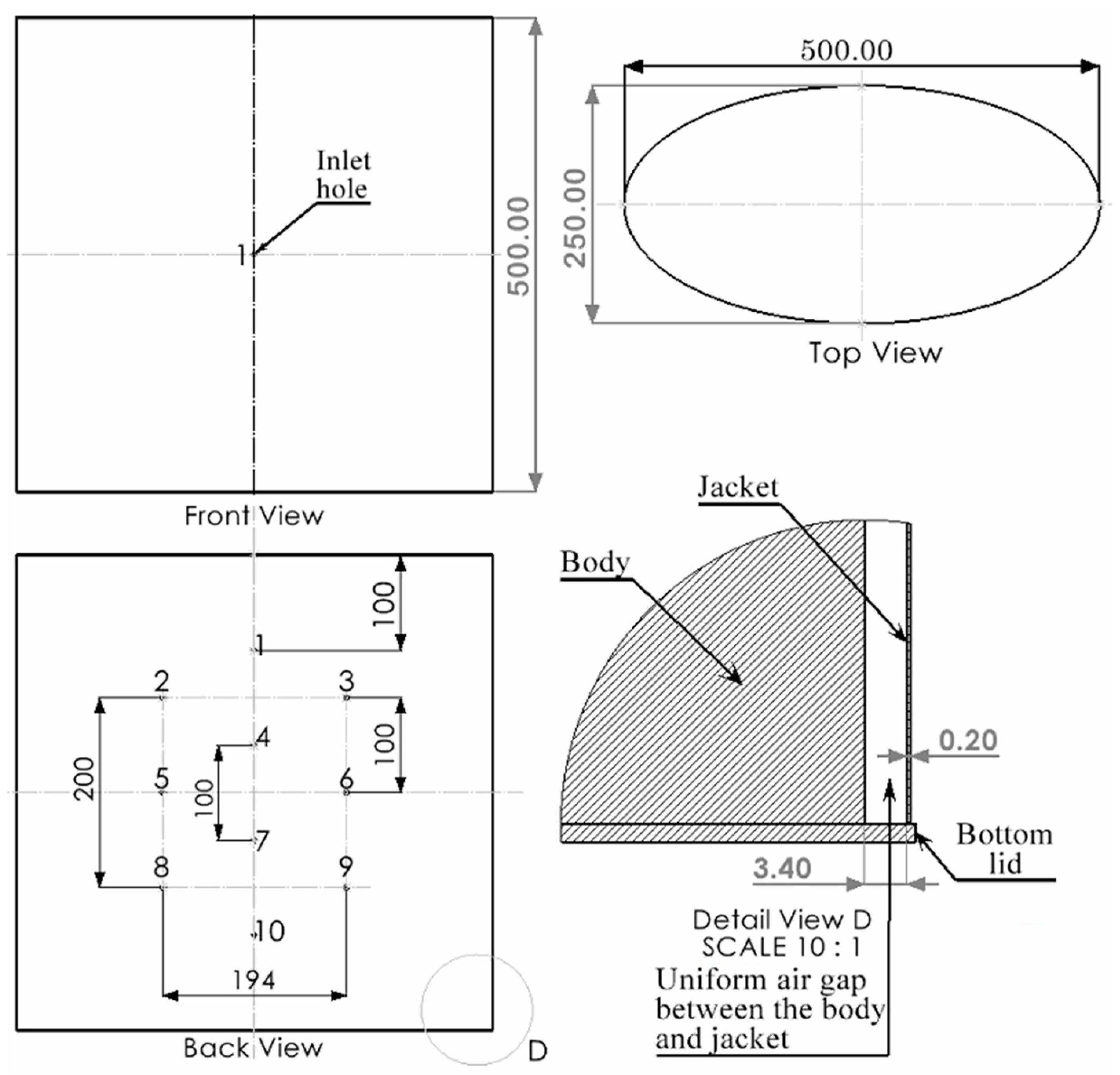
Figure 4 depicts a schematic diagram illustrating the simplified design of the human body and jacket, which are assembled such that the body remains in the center and a jacket is over it with a uniform air gap of 3.40 mm between them. The diagram shows a single inlet ventilation hole with a diameter of 4.4 mm at the front, while the jacket’s backside features ten outlets with a diameter of 4 mm each. A single ventilation element is attached at the inlet ventilation hole in the air gap between the body and the jacket, as shown in
Figure 4 (Detail View D), while no ventilation elements are affixed at the outlet ventilation holes, which are at the backside of the jacket. The ventilation element is positioned concentric to the ventilation hole, with the front face of the element directly aligned with the hole. This arrangement is depicted in
Figure 5, which includes an enlarged view of the ventilation area. The highlighted orange circle indicates the position of the ventilation hole. Here, a simple elliptical shape of the model representing the body and jacket is considered to reduce the complexity of the problem. The shape of the model itself will not have a significant impact on the final outcome as long as we use the same model for all 12 DOE, as the goal is to find the optimum shape of the ventilation element that can efficiently cool the body.
The simulation study was conducted using a set of 12 ventilation elements. The model is computed using SolidWorks internal flow simulation. This is a transient study, and the results are computed for a physical time of 5 s. The boundary conditions and computational domain of this study are illustrated in
Figure 5. The flow simulation investigation uses standard parameters of an initial air temperature of 20 °C and an air pressure of 101,325 Pa. The experiments are conducted at an air velocity of 4 m/s, which is set as the inlet boundary condition. The direction of air is perpendicular to the front face. The ten outlets on the backside of the jacket are assigned to environmental pressure as an outlet boundary condition. The average human body temperature is taken as 36.5 °C, while the rate of heat produced by the body under normal walking conditions is estimated to be 200 W [
19]. In the simulation study, different materials with specific characteristics are allocated to both the jacket and the body.
Table 1 presents the material’s properties. In the present study, basic cubic mesh of size (
Nx = 36,
Ny = 36,
Nz = 18) is employed in the flow simulation study, as using fine mesh extensively increases computational time. The flow simulation in SolidWorks uses a volume mesh. The total number of generated cells is 339,638, out of which 83,651 are fluid cells, 255,987 are solid cells, and 76,737 are fluid cells contacting solids. The final result of finding the optimum form of the ventilation element will not be significantly influenced by using a finer mesh, as the same set of values is used for all 12 DOE in this study. This is because the results obtained from the 12 DOE are compared and then further approximated in order to determine the optimum value.
Some assumptions in the flow simulation are outlined as follows [
18]:
The jacket is closed at the top and bottom to prevent air from passing through, allowing for an investigation into the efficiency of ventilation.
The study does not take radiation into consideration, as the heat loss due to radiation is assumed to be the same across all scenarios.
The process of heat transmission occurs through conduction and convection from the body to the jacket and, subsequently, to the outer environment.
3. Results and Discussion
After configuring the settings as outlined in the preceding section, a flow simulation study is conducted for a physical time of 5 s. Each of the 12 elements is analyzed individually, and the resulting data are assessed to obtain the required values.
Figure 6 shows the flow pressure for element 1, from which the value of dP is calculated. Here, element 1 is the geometrical model 1 shown in
Figure 3b. Similarly, each of the 12 elements is positioned simultaneously at the inlet hole, and the simulation study is re-run to obtain the desired values for each element. The results obtained for each element are displayed in
Table 2. The surface temperature of the body is shown in
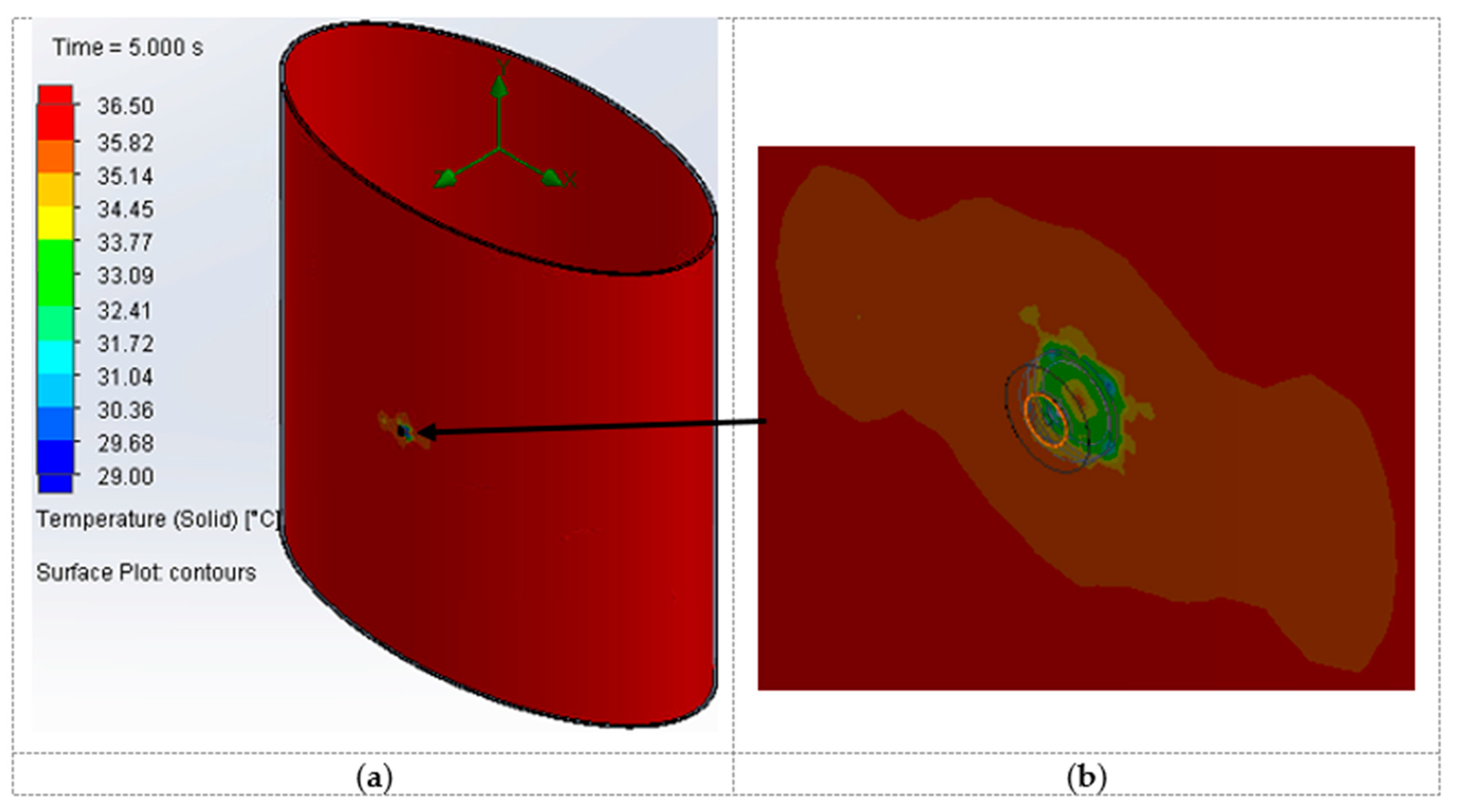
Figure 7, when element 1 is attached. The surface temperature difference is calculated from this plot. Similarly, the value of dT is calculated for each of the 12 elements, and the respective values are mentioned in
Table 2.
After the completion of the simulation study, we can obtain the values of HTR, H, ΔH, and HF using the surface parameter option available in the results section of the SolidWorks flow simulation. All these values for each of the 12 elements are listed in
Table 2. All the values of the criteria given in
Table 2 are relative to the body surface, except for ΔH and dP. The symbol ΔH denotes the heat transfer occurring through ventilation holes, and the negative sign indicates that heat is being released from the system (body). The criteria dP indicates the pressure difference, specifically in an air gap between the body and jacket, where air enters through the inlet ventilation hole with a ventilation element.
Based on Based on the results, it is evident that only the variables dP and dT exhibit sufficient sensitivity in their values for further approximation and optimization. In contrast, the other parameters yield nearly identical values for all 12 DOE, rendering them less valuable for the quality approximation. In our previous article [
11], we have already discussed the results of our study on optimizing an element with the minimum pressure difference as the criteria. From this investigation, we discovered that another useful criterion for optimization is the temperature difference, as most of the other criteria stated do not exhibit sufficient sensitivity. Further approximation and optimization based on the maximum temperature difference as a criteria are mentioned below. The optimization criteria here is maximum dT (minimum −dT), as our goal is to provide efficient body cooling. A higher dT results in better cooling, as the heat transfer rate increases with the increase in dT.
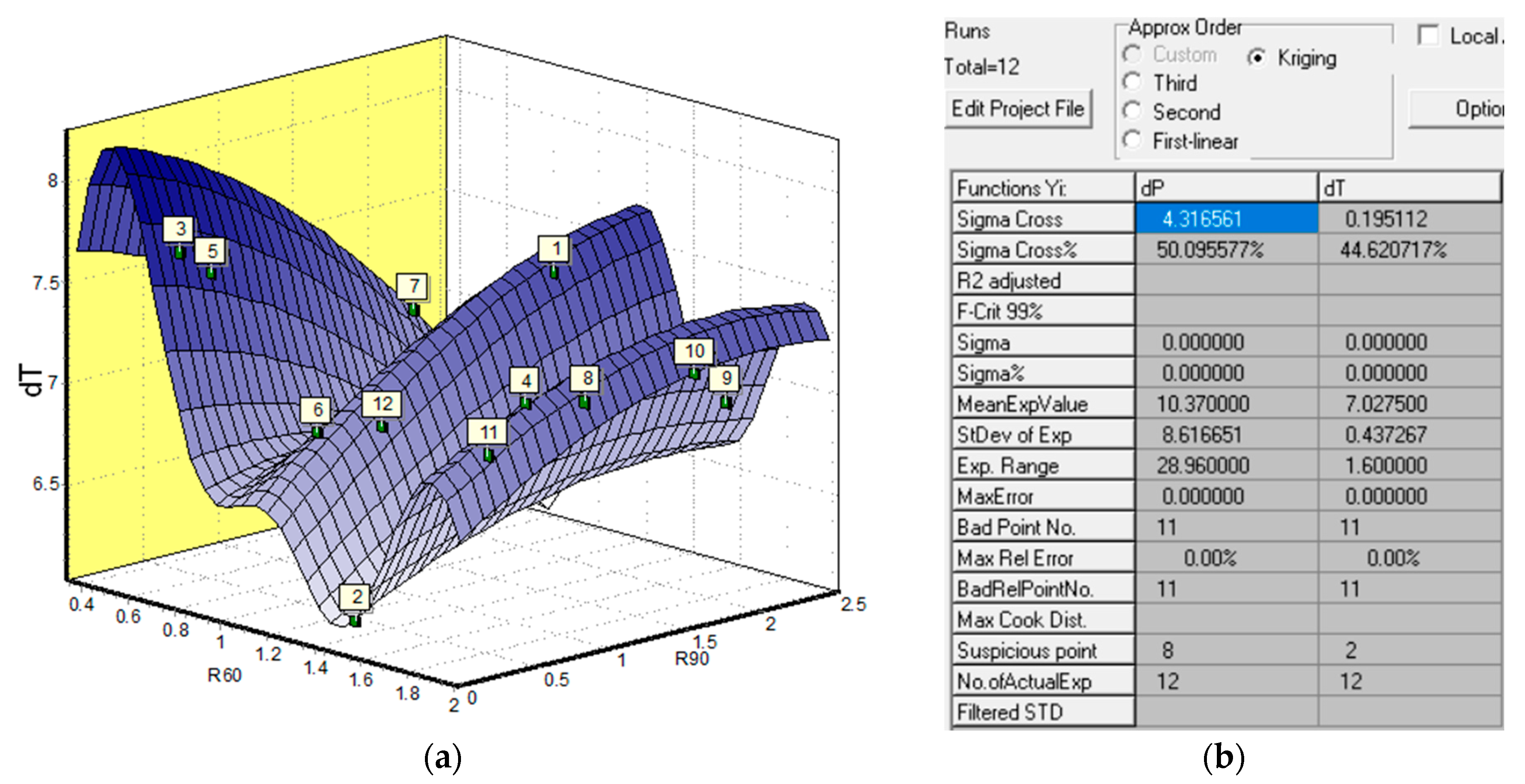
The values of dP and dT are entered into the KEDRO software as the responses for the approximation and optimization process, as shown in
Table 3. The next step in KEDRO is to select the approximation method after the responses have been entered. In this study, the Kriging approximation is used.
Figure 8 displays the Kriging approximation performed, with the response surface showing the experimental points. Two primary metrics for evaluating approximation quality are Max Rel Error and Sigma Cross%. Here, Max Rel Error is the maximum relative error (in proportion to the experimental values), and Sigma Cross is the leave-one-out cross-validation error.
where,
represent the value of the estimated function for input factor value
xi, when the
i-th experiment point is not used in the approximation, and
n—refers to the total number of experiment points. A more meaningful measure for assessing the accuracy of the approximation is the relative cross-validation error (Sigma Cross%), expressed as a percentage of the Standard Deviation (STD).
where,
is the average value of responses in the experiment points.
The quality of the approximation is severely lacking if the Sigma Cross% is close to or greater than 100%. On the other hand, a smaller Sigma Cross% yields better approximation quality. A lower value of the Max Rel Error also indicates a better approximation. In this case, as shown in
Figure 8b, the Max Rel Error is 0.0% and the Sigma Cross% is 50.09% for dP and 44.62% for dT, both of which show that the approximation is of good quality, though there is scope for improvement.
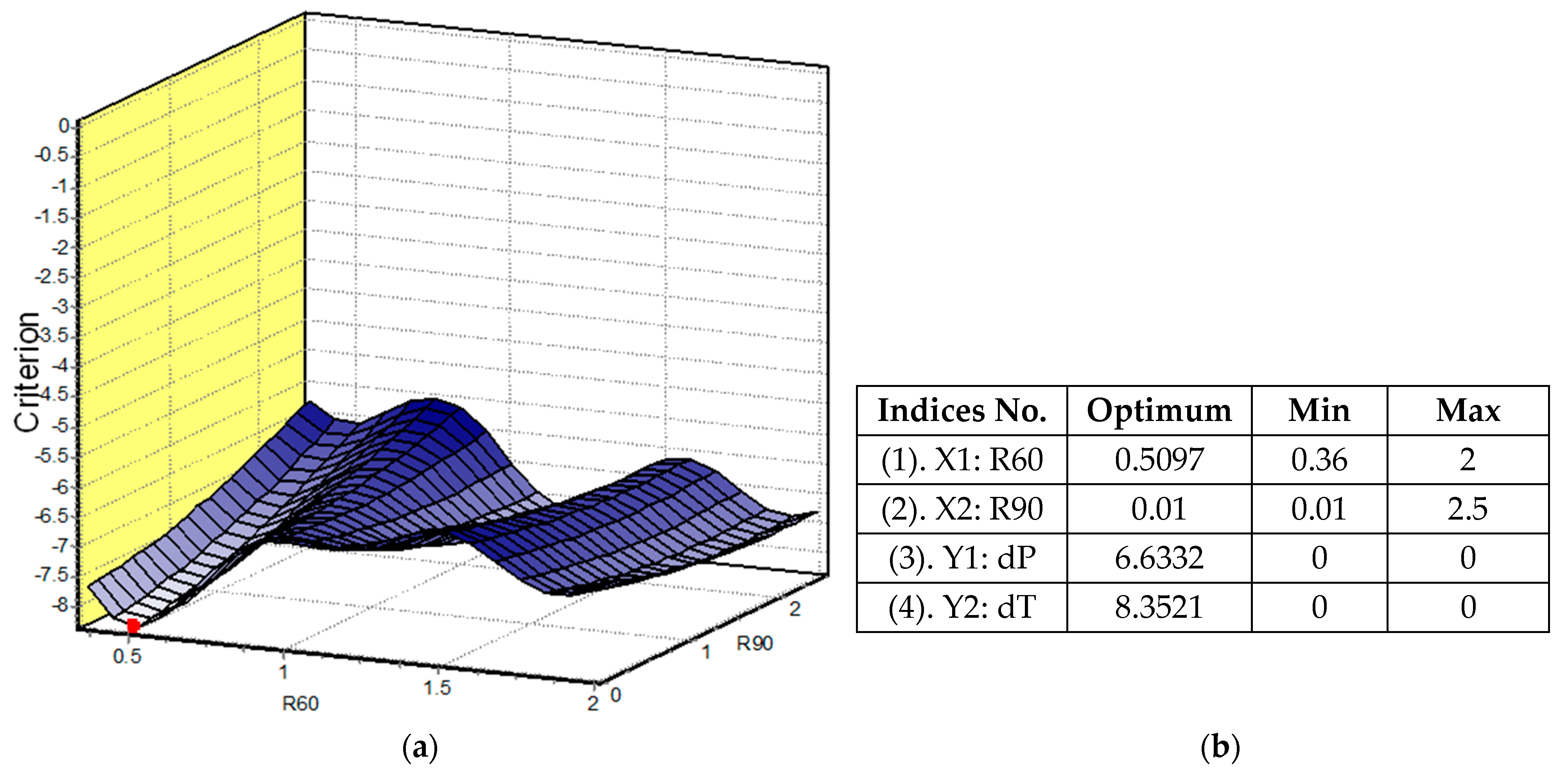
Figure 9 displays the optimization results using -dT as a criterion. The negative (−) sign indicates that the maximum value of dT leads to better performance, and 8.52 °C is the maximum value of dT that we can achieve with the optimal design of the ventilation element.
Figure 9a shows a cross-sectional plane of the criterion surface, with a red point representing the optimal coordinate position of the element design.
Figure 9b displays the optimal coordinate values for element design, denoted by the indices X1: R60 and X2: R90. The indices Y1: dP and Y2: dT represent the relative values of flow pressure difference and surface temperature difference that can be achieved by the optimal design of a ventilation element. Once the optimum values for the coordinates are determined, a geometric model of the ventilation element is generated in SolidWorks using the optimal values of R60 and R90 depicted in
Figure 9. Given that the coordinate values of R90 for both dP and dT are the same and very small (0.01), it can be concluded that there is no outer ring and that the geometrical shape of the element remains the same in both scenarios. This also shows the reliability of the technique, as we are obtaining the same optimal shape of the element by employing two distinct criteria: the minimum pressure difference and the maximum temperature difference. After creating the CAD model of the ventilation element, it is attached to the inlet hole of the model, which includes the jacket and body, as depicted in
Figure 5. The entire model is subsequently simulated in SolidWorks flow simulation to determine the flow pressure and surface temperature for the optimal design of the ventilation element. The values of dP and dT are calculated from the obtained results, which are shown in
Figure 10 and
Figure 11, respectively.
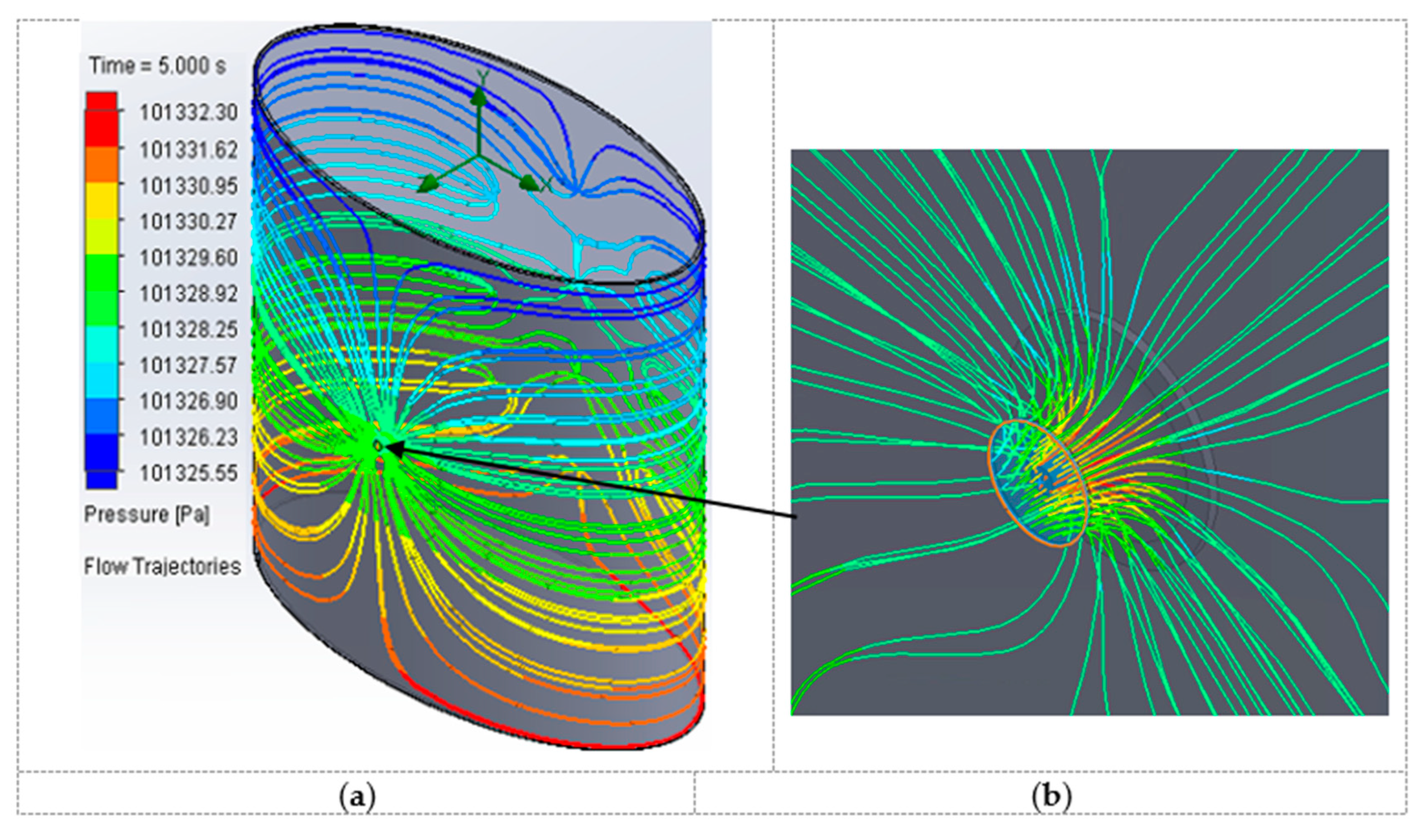
Figure 10 displays the distribution of pressure throughout the entire model when the optimal ventilation element is positioned at the jacket’s inlet hole. The pressure plot shows that the lowest pressure is located at the top of the model and at the outlet ventilations on the backside of the jacket, which gradually increases as the flow descends toward the bottom part of the model.
Figure 11 depicts the impact of ventilation on the surface body temperature. Because there is only one air inlet, the cooling impact is minimal. A more detailed viewpoint of temperature variation can be seen in
Figure 11b, with a zoomed-in view near the ventilation inlet. The blue dots indicate the location with the lowest temperature, which is within a relatively small area. The red area represents the highest body temperature, which is equivalent to the set normal body temperature in this study. The comparison between the results of flow simulation and optimization is presented in
Table 4.
The values obtained through optimization using KEDRO and SolidWorks flow simulation are close with a minor deviation. The difference depends mostly on the quality of the approximation and the CFD model. By improving the quality of the approximation, it is possible to acquire values that are very close with very slight variance. Furthermore, implementing a fine mesh in a CFD simulation can decrease the variation in the resulting values, but it also leads to a substantial increase in calculation time as the mesh level increases. The analysis indicates that the quality of the approximation for dT (Sigma cross = 44.62) is slightly better than that of dP (Sigma Cross% = 50.09). However, in both cases, the quality of the approximation is good enough to provide results with a minor deviation. This can be said as the obtained results of the flow simulation and optimization show a minor difference of 0.2 °C (8.55–8.35) for dT and 0.12 Pa for dP (6.75–6.63). The percentage difference between the obtained values is 1.7% for dP and 2.34% for dT. The error falls within the permissible tolerance as it is less than 5%.
4. Conclusions
In this study, different criteria were considered for the optimization of the ventilation element, and the results indicate that not all criteria values will show enough sensitivity for the approximation and optimization of the element. From the results, it is clear that dP and dT are the most appropriate and sensitive criteria for the optimization of ventilation elements out of all the criteria mentioned in this study. Moreover, both criteria provide the same optimal shape of ventilation element, which also shows the reliability of the process. However, dT shows a slightly better approximation quality than dP, which makes dT the most appropriate parameter for the optimization of ventilation elements. This is also true as ventilation elements are to be used in protective clothing to provide efficient cooling of the human body in warm environments or heavy work load conditions, and temperature is the best indicator to predict the efficiency of cooling.
This study convincingly demonstrates that incorporating a metamodeling approach with the CFD simulation can significantly decrease the computational time required for optimization. It takes over 4 h of processing time on a multicore computer with an i9 processor to conduct a CFD simulation for calculating a single criterion point for the stated problem. This time can vary depending on the study’s level of discretization and output requirements. However, by utilizing metamodels, the entire optimization process can be completed in just a few minutes. In the future, it enables the formulation of a more realistic shape optimization problem for ventilation elements, considering multiple inlet positions and uncertainties arising from factors such as varying wind direction.


