1. Introduction
CubeSat is a type of nanosatellite that began its commercial and research in 1999 when the CubeSat Design Specification was started in California [
1]. From the beginning, CubeSats were invented as technology for research and education. Since 1999, this form factor and the paradigm of nanosatellites have become popular in both commercial and military industries [
2], as well as in academia and in particular astronomy [
3]. Academic availability and access to such technology allowed student and science teams to gain access to research on space and the Earth from low earth orbit (hereafter LEO). A typical CubeSat is a nanosatellite ranging in size from 1U–10 × 10 × 10 cm up to 12U when several 1U units can be assembled together (stacked or placed next to each other). Usually, CubeSats are delivered to orbit as “parasitic load”, i.e., a secondary load. This is what makes its delivery to LEO very cheap, in comparison to the dedicated satellite launch. The typical programs for these parasitic launches of CubeSats are NASA’s CubeSat Launch Initiative (CLI) [
4] and the European Space Agency (ESA) program called Fly Your Satellite (FYS) [
5]. The method for the local “from the rocket” launch of satellites to orbit is a mechanically armed spring-based ejection, using particular load “dispensers”, for example, P-POD [
6]. The key reasons for the high popularity [
7], as well as the prosperous future [
8], of the CubeSats standard and approach are the low cost of such satellites [
9,
10]; the relatively short time of their construction and testing (which made it possible to construct, program, test, and launch a satellite during master’s degree students studies); and standardization. Standardization in its turn allowed one to reuse both individual parts of satellites and ground stations to receive telemetry and control satellites at LEO. The typical tasks of CubeSats include three types: the remote sensing of the Earth or other space objects, communication infrastructure (especially for CubeSats constellations, examples of OneWeb and StarLink), and the research of problems and tasks of re-entry into the Earth’s atmosphere. Looking at the statistics of launches and orbital deliveries for the past few years [
7,
11,
12], we can see rapid growth in popularity and further development of this area of space technology.
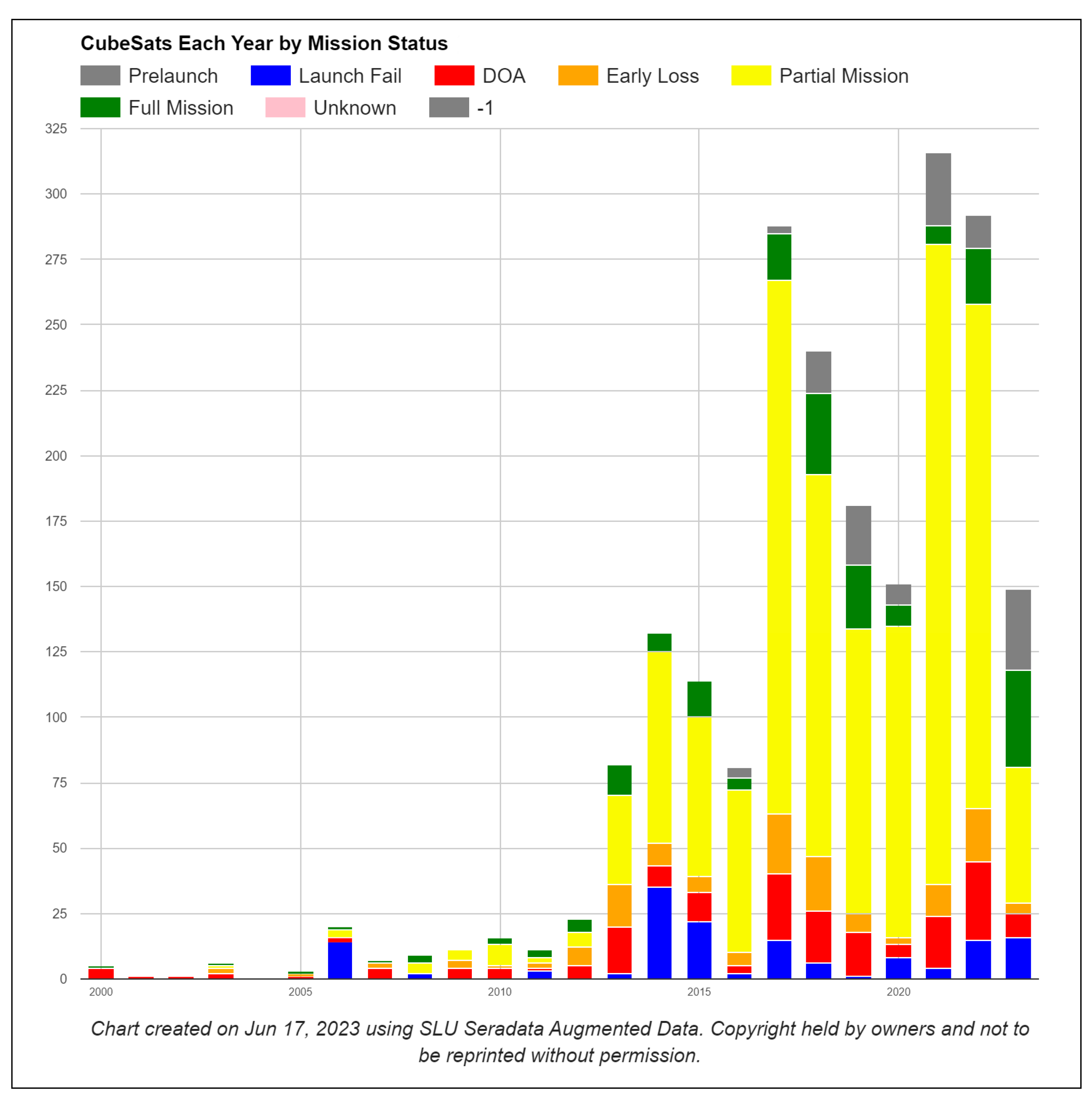
It is easy to see that almost 500 CubeSat satellites were launched in 2021 and 2022. Unfortunately, even with 20 years of launch experience and platform flight heritage, a relatively large number of launches remain unsuccessful. Looking at
Figure 1, we can see that approximately 18.5% of satellites in 2022 were completely lost, and only 2.9% of satellites fully completed their task (full launch mission). Numerous scientific and commercial teams worldwide strive to minimize the probability of either a full or partial satellite failure and maximize the percentage of satellites that accomplish their programmed mission. Such a need utilizes the following areas: general reliability, hardware and software design and development processes and techniques, hardware and software reuse, and verification and validation methods. As CubeSat design and development is a popular aerospace-related academic scientific project, many teams worldwide are trying to develop an entire satellite from scratch. This, in its turn, leads to the long duration, comprehensive planning, and execution of the project, and it establishes a very high bar for software and hardware development skills, which are not typical for academic people. In other words, teams are starting from scratch, trying to plan from the very beginning to the very end of the project, and running rigid but not yet mature software and hardware development processes. Looking into statistical data, it is clear that software development takes up roughly 2/3 of the time needed to complete a whole CubeSat project. The software development part of a typical CubeSat project always ends up being very complex and time-consuming. It involves defining, designing, developing, and testing (verification and validation, commissioning, and support after launch) the software. Even with a lot of earlier developed software reuse and open-source software use, it is still a significant challenge for the development teams to use the software properly and to obtain solid flight-ready software promptly. This article will provide an alternative approach to using a modern software development lifecycle, i.e., agile-like, and proper technology for the implementation, deployment, and use of the software. After the definition of a new development approach and its technical background is given, the authors make a top-level design of a CubeSat software structure in a newly introduced paradigm. To ensure that the proposed method is sound, the authors carried out a performance check on the selected variety of classical computer science algorithms.
1.1. How Is the Software Development Complexity and Processes Addressed by the Industry?
If we look into the typical ways of addressing the design and development of complex software, it is clear that the majority of techniques are divided into two major parts:
Technical design and development methods;
Improvements in the areas of communication, planning, and processes around the development process and development team.
The technical methods include but are not limited to techniques like decomposition, minimalism adoption, code from data separation, proper abstraction identifications, code reuse, etc., and the process and communication part is normally represented by modern software development life cycles, people and project management principles, and the so-called conscious collaboration paradigm. Looking into NASA’s own recommendations [
13], it is very clearly stated that the first-time development teams shall: “keep it simple” and “use familiar components”, and they “do not design to the limits”.
1.2. CubeSat Software State-of-the-Art
The whole idea of making a CubeSat cheap and easy to launch lies in the domain of using commercial-off-the-shelf (COTS) or modifiable-off-the-shelf (MOTS) components in both software and hardware parts of a typical development project. The use of COTS components opens up a wide variety of open-source and proprietary software to be used [
14,
15]. However, the use of the COTS software creates a huge number of troubles by way of the developing and proper testing of the CubeSat on-board software. Why? Well, many of the software parts are rather provided as the sample or
“take it on your own risk” and thus simply do not fulfill any reasonable metrics for production-ready software. This means that an increasing number of development teams are leaning towards the very comprehensive testing of the final assembled flight software, simply to ensure its quality and readiness to go to space. The majority of the research is focused on a very thorough verification & validation (V&V) approach [
16], using complex data validation models and techniques [
17]. Other research papers propose software in the loop (SIL) and/or hardware in the loop (HIL) simulation [
18]. Various efforts are also made in the field of failure emulation mechanisms (FEM) [
19], as well as the introduction of different fault injection platforms (FIP) [
20]. All these methods are very typical for the ”waterfall’ software development lifecycle and overall project management, as well as for rigidly and thoroughly planned projects. The rigidity and thoroughness are truly nontypical for academia and research projects where the mindset of “greenfield exploration” is commonly used.
1.3. Why the CubeSat Software Is Complex to Develop?
When we look into what actually makes CubeSats development a complex and challenging task, we can see a few major factors. The first and widely underestimated factor is the cyclomatic complexity of making CubeSat software. It is rather easy to see that even on the first order of a functional breakdown, CubeSat software demonstrates a complex set of sub-systems and their functions. The second factor is the skillset of the undergraduate and/or postgraduate students who did not have the option to obtain the industry practices and did not make their own so-called rule of 10,000 h of experience. It leads to a bunch of issues related to both architectural and implementation errors, and low awareness of the more effective tools and approaches for making software solid and robust. Last but not least, a major factor lies in the attempt of “blind” reuse of the open-source software (OSS). The push towards this reuse is normally given by the following factors: other team successes, strict and tight project deadlines, and focusing on the payload rather than on a whole CubeSat system. Such reuse leads to the low quality and maturity of the source code, and a lack of time to properly overview the entire code being developed. At the same time, CubeSat systems, including ground stations, communication signals, and CubeSat spacecraft, are subject to various cyberattacks, the classification of which is given by the standard ISO/IEC 15408 [
21]. There are various papers that analyze [
22] and propose methods for analyzing CubeSat security threats and solving those, for example, based on the analysis of attack trees [
23].
1.4. What Programming Language and Operation System Are Used?
Without a doubt, the “C” programming language is the number one choice and the de-facto market standard for embedded systems and thus CubeSat’s software development [
24]. The following factors contribute to the popularity of “C”:
It has minimalistic overhead, which is a must for the low power systems;
It allows one to use both COTS and a truly proprietary hardware (processor) platform;
Typical CubeSat FSW requires a lot of near-hardware programming, where “C” is very powerful and effective;
It requires less time to start development (in comparison to object-oriented languages such as C++ or Rust).
Therefore, in this article, the authors concentrate on the use of the “C” language for the experiment. With the experimental work, the authors will later compare the performance of the pure “C” code and “C”-written containers for the WASM3 containers engine. The term “Native C”, is introduced later in the article, means the C-language written software that is compiled by a dedicated and specialized to the specific hardware platform compiler. In other words, it is the most effectively compiled source code for a given hardware platform. Looking into the operation systems (OS) used in the CubeSat industry, it is pretty clear that it is an OS called FreeRTOS that is leading the development team’s choice [
25]. Therefore, FreeRTOS is selected to be used for all the following experiments described in this article.
1.5. How Does It Look from the Process Side?
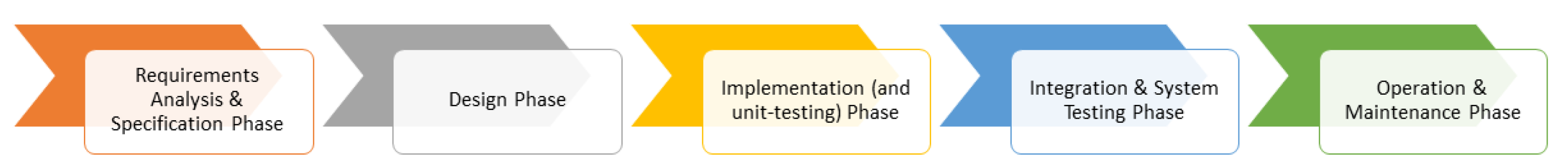
So we learned the technical challenges of the software source code development. The other major side of the problem lies in the way software development is planned and carried out—this involves addressing the software development lifecycle (SDLC) and general project management model. The common project and thus software development lifecycle for the space projects is still the “waterfall” one. The “waterfall model” is a linear-sequential life cycle model and was the first process model to be introduced and shown in
Figure 2. It is very simple to understand and use. It is a breakdown of project activities into linear sequential phases, where each phase depends on the deliverables of the previous one and corresponds to a specialization of tasks. Typical major stages of the waterfall model are:
“Requirements analysis and specification phase”: the phase when a project team gathers together and elicits and writes down all applicable project requirements. This phase usually ends when all project team members and a customer or a client agree that all requirements are final and fully defined. After this phase, it is assumed that requirements never change and are ready for design and implementation;
“Design phase”: the phase where the engineering team designs parts of the project having the requirements compiled in a previous stage. Normally, such a phase delivers two documents: a software design document (SDD) and a hardware design document (HDD). If some of the requirements cannot be fulfilled by the design, the design phase is considered as “non-feasible” and the project returns to the previous phase: “requirements”;
“Implementation (and unit-testing) phase”: the main phase where the development team associated with the project gets the software/hardware done. If something from the design cannot be implemented in unit-tested, the phase is considered as unfinished and the project shall return to the previous phase for either design or requirements elaboration;
“Integration and system testing phase”: the phase where all parts of the project are put together for the system-level testing. This is where the majority of problems appear because of either design and/or implementation errors or non-foreseen conflicts. Normally, this phase is the most heavy one and, in fact, is the most eye-opening for all project members due to integration “surprises”;
“Operation and maintenance phase”: the phase where the developed software and/or overall system delivers its designed value to the customer. This phase normally consists of adding further new functions to the software, fixing found during the operation bugs, and adopting the developed software to the changing product environment.
The waterfall model is a heritage of 1950s engineering and is bounded to standards like MIL-STD-499 [
26], MIL-STD-1521 [
27], and IEEE-15288 [
28]. It is rather clear from NASA’s “CubeSat 101 Handbook” [
13] that the recommended approach to the development of a CubeSat software is purely sequential and thus is of a “waterfall” life-cycle too. It is mainly driven by two common facts: industry practice and heritage and the fact of having and actually constructing the hardware in a CubeSat project. These are the factors that lead the entire project to be within the “waterfall” development life-cycle. What does it consist of?
The problem that is created by the waterfall development process is not only in its method of structuring the pipeline of the tasks but also in the the way the source code design, development, testing, and structuring are carried out. After conducting an analysis of the existing CubeSat projects available on GitHub, it became clear that the structure of the source code is weak and often primitive. Even regarding the projects where the code structure is executed in a modular manner, it is still made as a monolithic, tightly bounded, data/code coupled piece of software. Often such a monolithic approach is inherited from the framework being used as part of the re-use strategy. Knowledge of the development time and technical skill constraints in a typical CubeSat software development team, such a monolithic and tightly bounded structure, has never been challenged or changed. So how can the problem of a waterfall development model that is “reinforced” by a tightly coupled data/code and monolithic structured source code be solved? The answer is simple and clearly stipulated by the NASA “CubeSat 101 Handbook” [
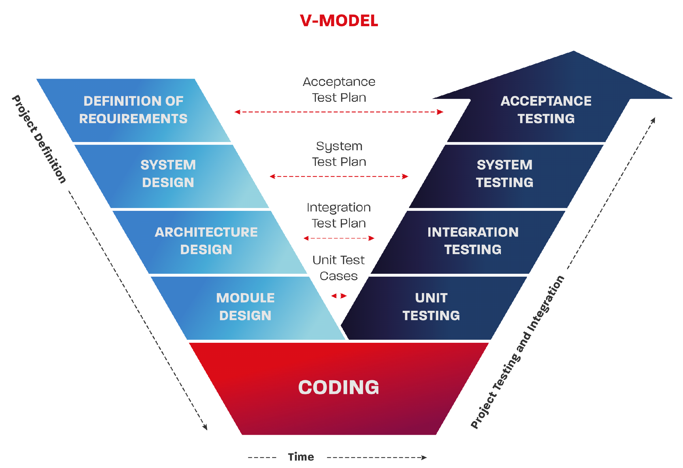
13]—it involves carrying out proper testing! Testing and quality control and assurance are by themselves very skill-demanding areas, and thus, in the majority of CubeSat projects, software, and hardware testing are pushed to the very last moment and undergo only integration testing. If we take the more mature development teams (mainly those who are part of commercial companies), they are using the so-called V-model that comes from the functional safety world where every step of the SDLC shall be properly verified after being accomplished. The V-model is widely used in applications driven by the following standards: IEC 61508 [
29]—“electronic functional safety package”, IEC 62304 [
30]/ISO 14971 [
31]—“medical device software”, ISO 26262 [
32]—“automotive functional safety”, etc. It is represented below in
Figure 3.
With the use of the V-model SDLC, the development team can better decompose the “design phase” and “integration and system testing phase” mentioned above and have more time to design/test the system at different abstraction levels. This in return helps one to obtain a better overview of its functions and addresses the functions’ complexity better. However, it is important to state that the use of the V-model does not change the fact that the integration is pushed to the very end of the development process and still requires a lot of development and testing efforts in the very end of the development. Using such an approach gives a closer look into the verification and later validation of the software but does not change either the design thinking or design approach of building the CubeSat software. Generally, both “waterfall” and “V-model” are widely criticized by the software industry due to their rigidity, simplicity, inflexibility, and linearity. It is important to emphasize that the use of the V-model does not improve the speed of the integration simplicity of the source code, it just helps to use more time for the design considerations at the different abstraction levels.
1.6. Era of Agile
However, nowadays, the majority of the so-called “big IT” software development teams and specialists are eager to use iterative and/or incremental software development models, i.e., based on agile processes, for example, SCRUM (see
Figure 4 or Kanban).
Such an approach means that the whole CubeSat software is broken down into chunks of “features” (functions) that are ready to be implemented, tested, and demonstrated as a separate stand-alone function. Looking into the research “Using the Event-B Formal Method for Disciplined agile Delivery of Safety-critical Systems” [
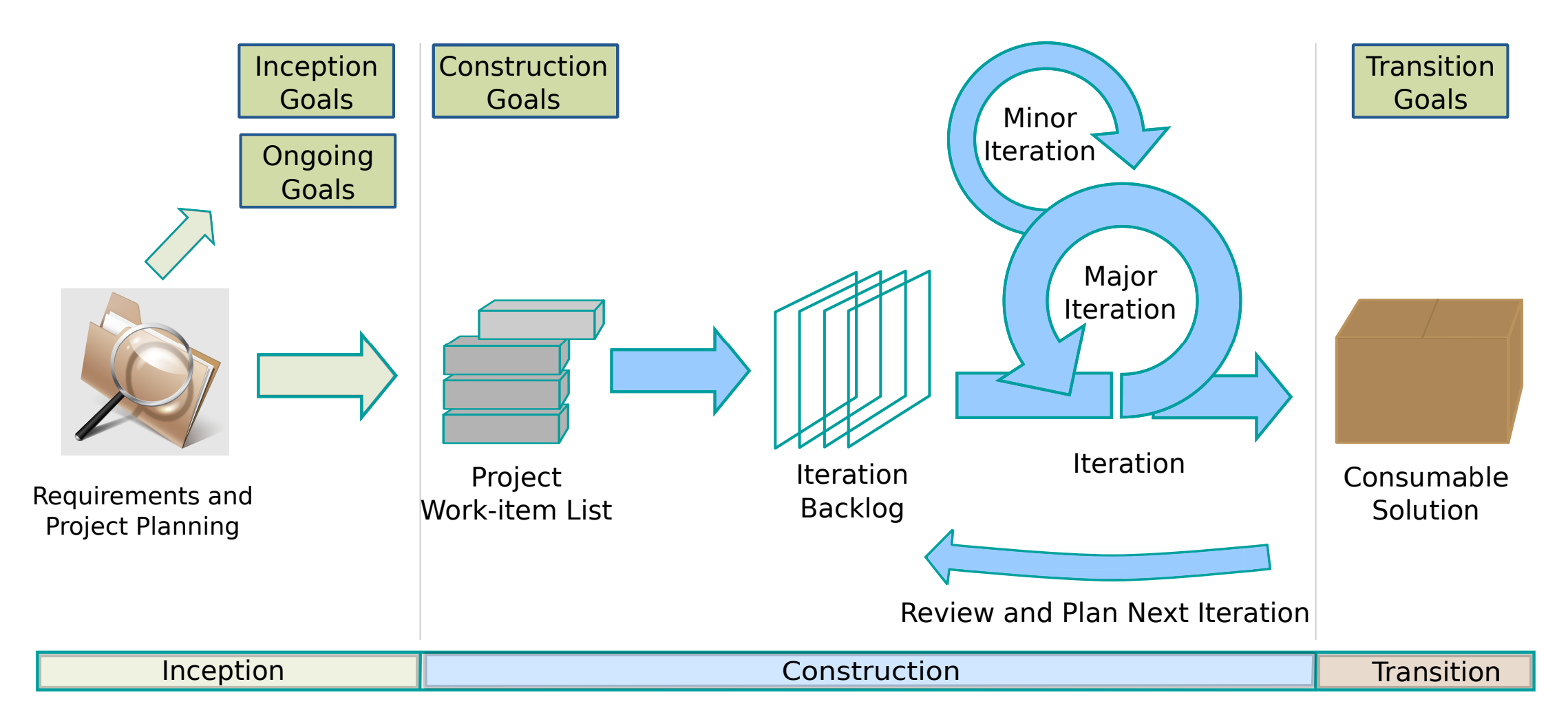
33] available, it became clear that there are many alternations of this classical SCRUM process that fit better into mission-critical software development that might be more applicable for the CubeSat projects and shall be further investigated. One such example is a development framework called disciplined agile (DA) and presented by the
Figure 5, which represents the process parts shown below.
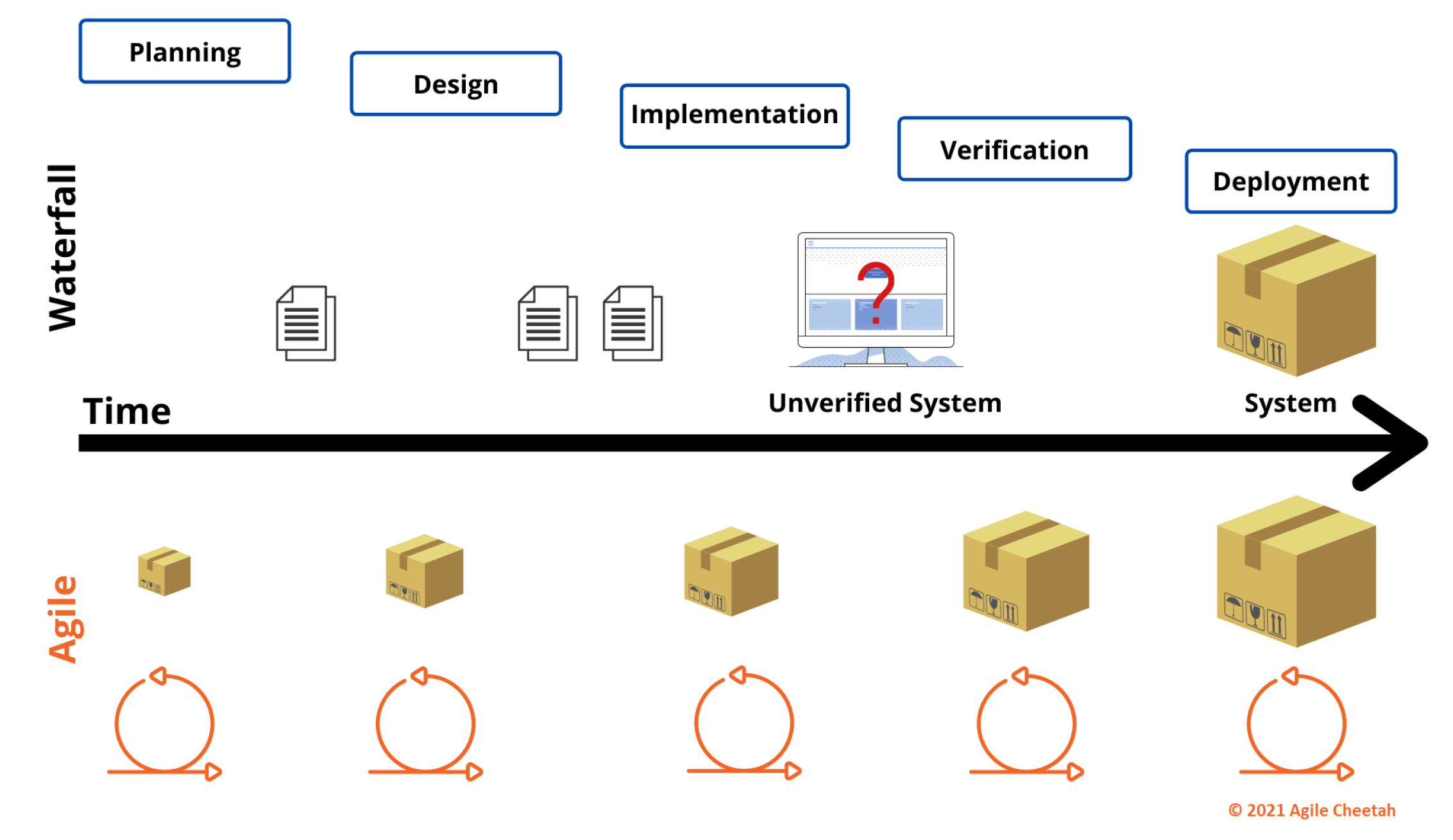
Based on the statements and found problems of the waterfall and the advantages of the agile (SCRUM, DA) development models, the authors suggest moving the CubeSat software development and overall integration of the satellite to the agile model while the hardware parts mature via the classical waterfall model. Accordingly, the authors suggest using the hybrid model, which is becoming commonly used in embedded electronics development. A simple visualization of the benefits is shown below in
Figure 6.
As it could be seen, the main difference is shown by the question mark symbol. It emphasizes the problem of too late verification of the entirely developed software, rather than testing smaller but completed deliveries (as shown in the Agile part of the figure).
1.7. Accompanying Development Model and Software Life-Cycle with Proper Software Structure
So, what are the problems that are identified by the authors? Two central problems: the waterfall development process, and monolithic and tightly coupled onboard software. How can these two be cracked? We have already addressed the process side by introducing the “hybrid” development model that combines the strengths of the agile and waterfall processes.
The next problem that was identified and addressed by the authors was the problem of a software design approach that was biased towards a monolithic piece of software being developed. The authors propose to address relatively newly introduced embedded software principles, such as microservices architecture and further containerization. These are good candidates for providing a counter-solution to the monolithic, tightly coupled, and ”waterfall”-based developed software.
1.7.1. Microservices
A microservice is a single service built to accommodate an application feature. It handles discrete tasks within a microservices architecture. Each microservice communicates with other services through simple interfaces to solve business problems. The key benefits of the microservices are that they are:
As can be easily seen, all of the problems identified in
Section 1.3 of a typical CubeSat software are addressed by the nature of the microservice. The idea of using microservices architecture opens up the migration options for the initially monolithic software via the use of the ”strangler application” design pattern. The process of such migration is called “Strangling the monolith”. The industry of software development is rapidly booming in using such an approach, and there are numerous metrics and tools related to this topic [
34].
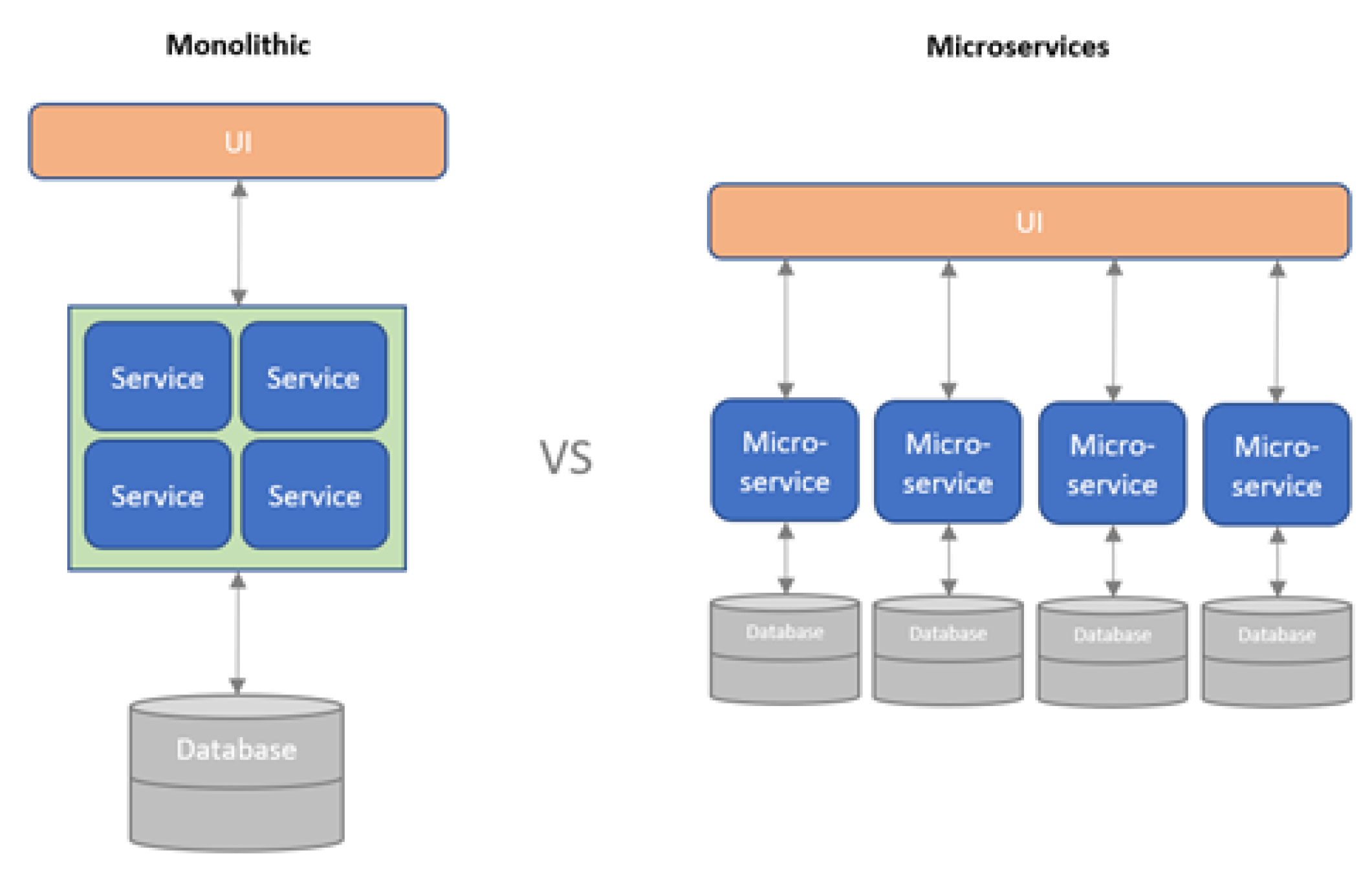
1.7.2. Microservices Architecture
What is the microservices architecture? It is a development concept in which the entire software to be built is broken down into several small, independent, and loosely coupled services that communicate with each other. The communication between those microservices can be carried out using HTTP, WebSockets, AMQP, or even MQTT. The simplest way to explain the difference between microservice-based and monolithic architectures is to demonstrate the following
Figure 7:
Obviously, connecting such a decomposition approach to the idea of a SCRUM-like decomposed process when developing smaller fractions/modules of the CubeSat software makes perfect sense. Practically, this will allow the CubeSat teams to develop different software modules simultaneously, isolate quality issues and errors in a particular module of the software, reuse someone’s else modules in a much simpler manner, and use a bigger development team to shorten the time of the development. Having said that, the one big limitation still remains unsolved is the non-continuous and low-to-medium-skilled development teams. Microservices architecture is based on a strong and well-designed message and event exchange structure, where the typical undergraduate and postgraduate students are simply not skilled enough to reach the interfacing agreement.
1.8. Introducing Containerization
What containerization in a broad sense is? According to IBM [
35], one of the frontiers of developing the concept and bringing it to the industry, containerization is the packaging of software code with just the operating system (OS) libraries and dependencies required to run the code to create a single lightweight executable—called a container—that runs consistently on any infrastructure [
36]. More portable and resource-efficient than virtual machines (VMs), containers have become the “de facto” compute units of modern cloud-native applications and successfully moving to smaller hardware platforms. Containers are called “lightweight“ because they share the OS kernel of the machine and do not have to load an OS for each application. It makes containers smaller and faster than virtual machines and allows more containers to run on the same computing capacity. For the embedded microcontrollers (smaller than a CPU), the classical virtualization would not fly anyway as the resources (Flash, RAM) are still too low for the completely separate VM(s). The main benefit of containerization is that it enables applications to be “written once (on one platform) and run anywhere”. This means that developers can create and deploy applications faster and more securely across different platforms and clouds without worrying about bugs or vendor lock-in. Containerization also offers other advantages such as fault isolation and tolerance [
37], easy management, simplified security, and more. Perhaps the most essential thing is that containerization allows applications to be truly portable and platform-independent, i.e., “written once and run anywhere”. This portability accelerates development; prevents cloud vendor lock-in; and offers other notable benefits such as fault isolation, ease of management, and simplified security. As the importance of embedded applications is rising, hardware capacity is increasing—the development of the microservice architecture and packing of it into containers on embedded systems is booming. There are many examples of home-baked frameworks that are increasingly changing developers’ mindsets into microservices-based architectures [
38]. Having analyzed the mentioned approaches, the authors suggest using the containerization approach as shown in
Figure 8 and implementing the typical onboard software tasks as microservices and placing those among the containers. To be able to do so, the first step would be the selection of a proper container engine (or so-called framework).
1.9. Available Containerization Frameworks
During the analysis of the IEEE Xplore, Scope, and Google Scholar papers on the matter of embedded software containerization, the following container engines were found:
MicroPython;
Jerry Script;
Singh;
Velox VM;
Toit;
Femto containers;
Wasm3;
Golioth;
Others.
After conducting a top-level analysis and reviewing it, it became clear that each container engine is more or less based on the WebAssembly principles of real-time code translation. WebAssembly was initially developed by the W3C organization as the translator for web-technologies and applications. Later on, because of its popularity, it became a good choice for the cross-platform engine for non-web applications too. Partially its popularity is driven by the support of the native to the typical embedded software programmings languages such as C, C++, and Rust. As of today, there are more than 35 implementations of high-performance WebAssembly machines, roughly 50% of which are actively supported and continue their lifecycle. During the desktop analysis of the above-mentioned WebAssembly implementations of the container engines, the main focus was on three things: ease of migration and adoption of the most commonly used hardware platforms; the existence of already completed ports for easy-to-get COTS hardware platforms; and, last but not least, the royalty-free nature of the engine, so the concept of COTS components of CubeSats is still kept. As the basis of the solution of the container’s engine implementation on the typical CubeSat hardware, the WASM3 [
39] interpreter engine was chosen. WASM3 was initially created to deliver outstanding performance for the low-performance targets and thus fully supports the energy-efficient and low-performance hardware of CubeSats. The other neither qualitative nor quantitative selection factor was that WASM3 was developed and actively supported in Ukraine. This will allow the authors to establish a direct connection with the WASM3 development team and by this ensure further work on the use of containers for the CubeSat applications. To be able to better understand how containerization could help CubeSat development teams, let us look into a typical CubeSat system structure and identify the conceptual way of implementing containers for CubeSat projects.
1.10. Combining Benefits of Microservices and Containeriztion
So far, we have solved a monolithic “one-does-it-all” code problem and have moved to a set of microservices, that represent a standalone function of the onboard software. The next step that is proposed to be solved is the proper “isolation“ of the microservices so they are not influencing each other’s stability, ensuring reliability and allowing for faster integration. The authors suggest solving this via the distribution of the microservices to a set of containers. Each container will consist of a much smaller sub-set of the microservices related to the high-level business function of a CubeSat, i.e., “communication” or “altitude determination and control module”.
1.11. Hidden but Yet Important Advantages of Containerization
In a typical CubeSat project, the hardware and the test stand where the software and overall integration testing are carried out are very scarce resources. Therefore, there are a few hidden yet important benefits of the use of containerization:
The ability to develop and test the container on a regular PC, rather than CubeSat hardware. It minimizes the need for the test stand availability and minimizes the risk of breaking the working hardware;
Full isolation from the other developers with different (lower) qualifications in a frame of the particular container scope. This means that software errors and malfunctions in other containers will not destroy your own work;
Easier profiling of a container performance as the developer may just stop other containers at any given point in time.
2. Materials and Methods
2.1. Finding a Unique and Proper Combination of Development Approach and Containerization with Micro-Services Use
In order to evaluate the possibility of using the WASM3 container and microservices-based software, it is essential to evaluate the technology’s ability to meet the requirements of real-time systems, that is, to guarantee the execution of a specific task at a predetermined time. Compliance with real-time requirements is a mandatory component of every dependability system. It is especially true of the nanosatellite software when the loss of communication or power supply leads to the loss of the entire satellite. In this part, it is necessary to consider the system’s compliance with two requirements: soft and hard real-time. Soft real-time is when, on average, the execution time of the algorithm does not exceed predetermined limits; hard is when each violation is a possible reason for the disruption of the system as a whole. The work aims to estimate the overhead and additional costs of meeting the performance requirements of software algorithms, both from the point of view of soft and hard real-time requirements, if the software architecture includes microservices based on the WASM3 interpreter. Microservices provide more opportunities for the independent implementation of individual student projects and their subsequent integration into a single whole, but the question of how much such an opportunity will cost remains unanswered. It is already clear that the transition from a program compiled and tailored for a specific processor to a program interpreted by a shell requires additional processor time due to additional costs and limited available onboard energy. In order to meet the evaluations required, the next part of the article will provide readers with the essence of the CubeSat structure. Such an overview will show us the typical approaches to a CubeSat software decomposition and implementation, and the author’s proposal on the new method of implementing the onboard software based on WASM3 containers with the microservices-based software modules.
2.2. Typical CubeSat Software Structure
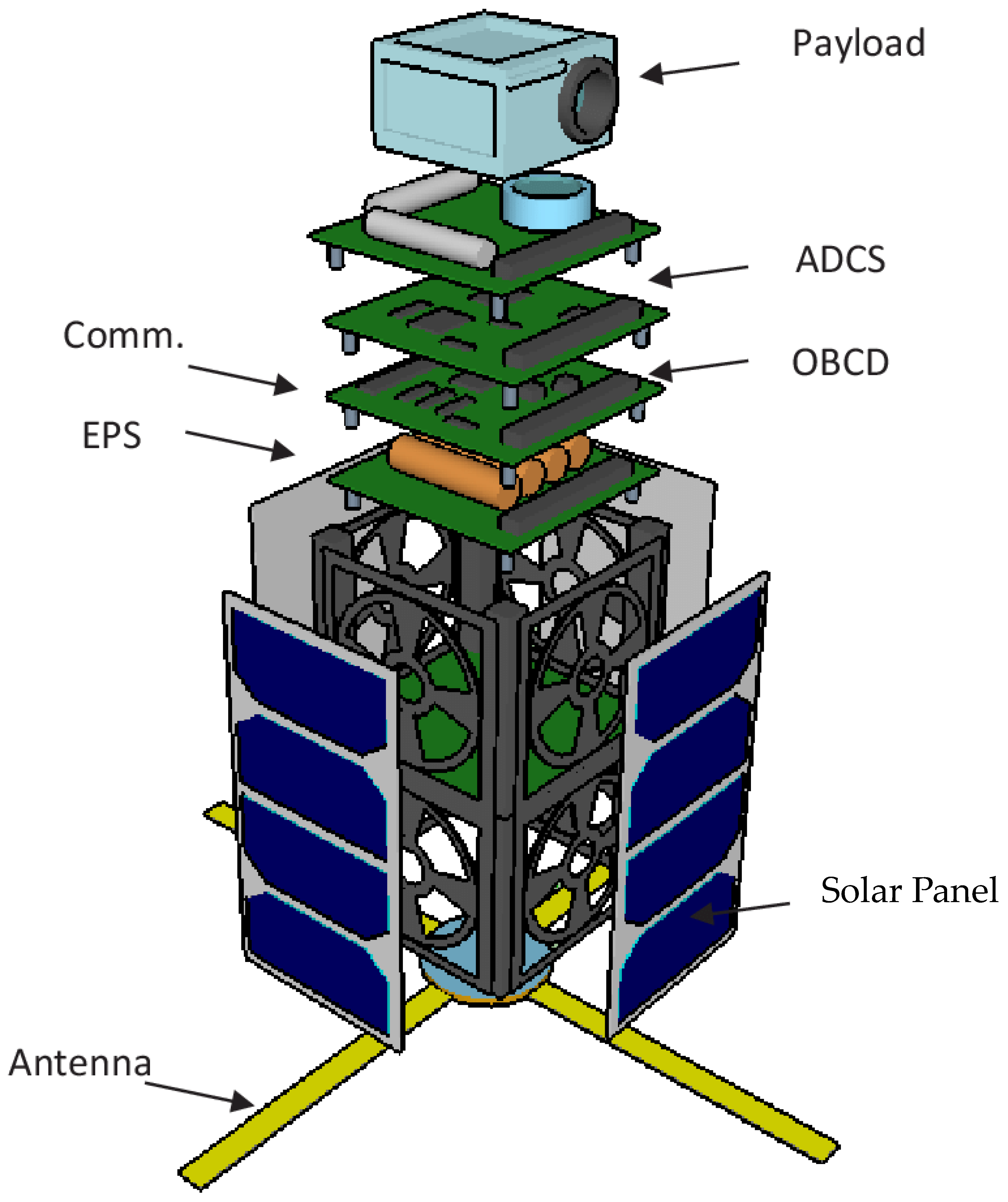
To better understand and break down a problem, let’s look into a typical CubeSat build shown in
Figure 9 and
Figure 10, and how the declaration of the author’s techniques can be used for its system and software design. A CubeSat normally consists of a few main electronics systems:
OBC(D): on-board computer (and data);
ADCS: an altitude determination and control system;
EPS: electronic power system (could include batteries);
Comm (or COM): communication system;
Payload: the “mission” of the CubeSat that brings business value to its creators;
Propulsion: a propulsion system that is typical for a more advanced and bigger (6U+) CubeSats.
Additionally, there are a few non-electronic systems (which are out of the scope of this document): solar panels, batteries, antenna(s), and the mechanical structures around which all the modules are assembled.
In some pretty complex CubeSat build-ups, OBC(D) and ADCS could be combined and called CDHM, which stands for the command and data handling module. This article will address this module in particular as the most software-heavy and complex of any CubeSat project. If we look into a typical method of implementing the software for such a CubeSat platform, there are two main approaches:
Approach A: An OBC/CDHM only coordinates the data exchange between the rest of the system components, where each component has its firmware and program. See
Figure 11Approach B: An OBC/CDHM does it all. All other components are as “dummy” as possible. See
Figure 12;
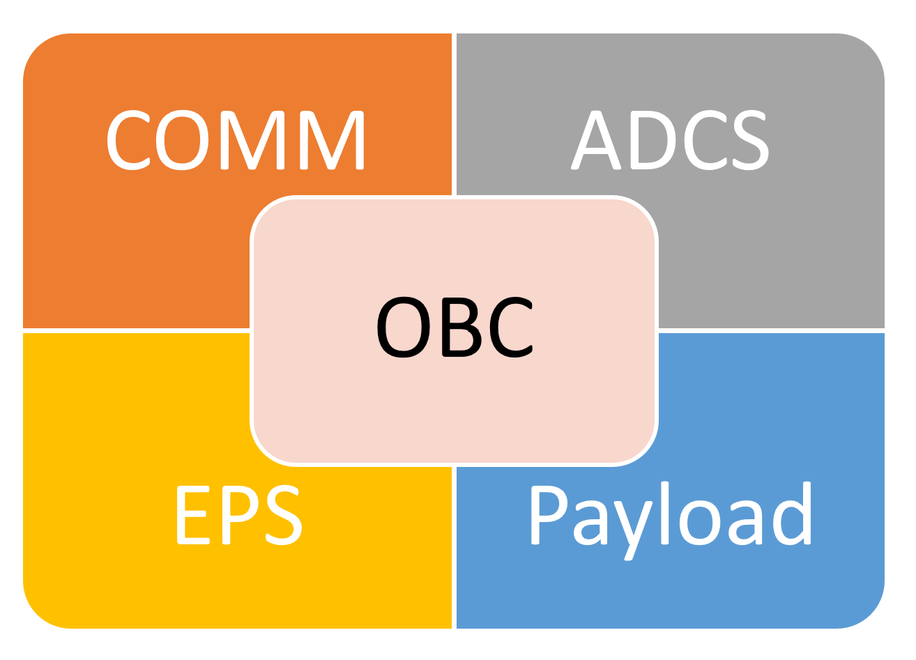
To be able to perform the mission, both approaches A and B shall basically implement the same software. However, the number of CubeSat components and sub-systems will impose different complexities on the software, its structure, and its data footprints. The typical OBC/CDHM software (both approaches A and B) could be represented as the following main software building blocks, where the OBC/CDHM handles the main control block and other modules represent different system and payload functions.
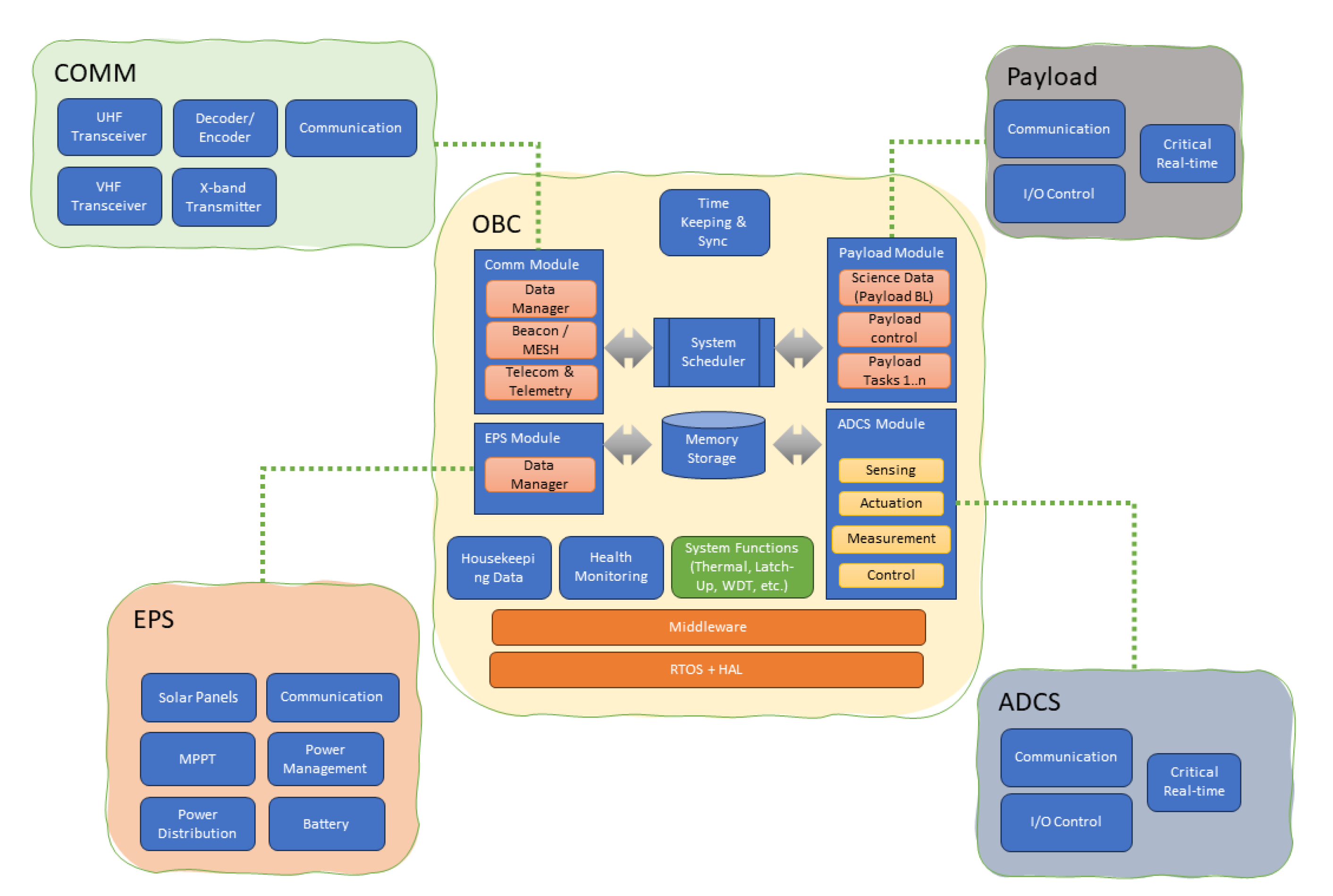
The CDHM normally represents either a server in a client-server architecture of CubeSat software, or a central data and task scheduler in a more classic OS-like CubeSat system architecture. Further breakdown of the data flows and the software components of a typical CubeSat can be represented as follows:
It is reasonable to assume that it is a typical Approach A system architecture that requires several comparable calculation power processors/microcontrollers to be embedded in each system board. Therefore, the energy consumption, complexity, cost, and, last but not least, the probability of a hidden error are at their maximum. This is also a very clear example where each separate component of a CubeSat will be designed in a monolithic manner. Making a separate system component (especially one that runs on separate hardware) in a monolithic manner is rather typical for the industry. The big problem with such distributed yet monolithic systems comes with the integration tests complexity, where the bug-finding efforts and time are very costly and the overall project is very much pressed for time.
Instead of such a monolithic system architecture, the software can be designed differently by the use of containerization and microservices. Instead of having many smaller different monolithic components in the system that are compressed into a big one, the business and control logic of those modules is spread towards the containers and corresponding microservices. Each container can represent the particular system component, and in that way, strictly breakdown functions across containers. The suggested approach is represented below in a
Figure 12 (Approach B).
In this approach, the utilization of the centralized EventHub and EventBus, which is used for the data and commands exchange, can be enhanced by the introduction of the “exposed” EventBus to the communication modules of the other CubeSat components. In this way, the whole system control can be synchronized and orchestrated by the “Saga” pattern or similar. At the same time, such an approach solves the problem of complex and non-uniformed multiple firmware files over the different modules and thus reduces overall project complexity. The majority of the development work moves to the OBC/CDHM side and requires a system architecture response to make it easier to handle, i.e., by using design patterns like “Saga” and adopting a proper database. Surely, the modern approach of using RTOSes, aka FreeRTOS, embOS, and Salvo, allows for a proper abstraction level and the modularity of the complex OBC/CDHM to be designed properly too. However, the main problem of the monolithic firmware, which is still the industry practice, remains active. The monolithic implementation approach of such logically broken down and modularized software brings challenges that are typical for both waterfall development models and overall software quality complexity and cost. Normally, these challenges are integration complexity and time, the many iterations of the re-design of the data exchange and APIs, complex bug-finding and fixing, etc.
2.3. Implementing a Concept CDHM Software on WASM3 Container
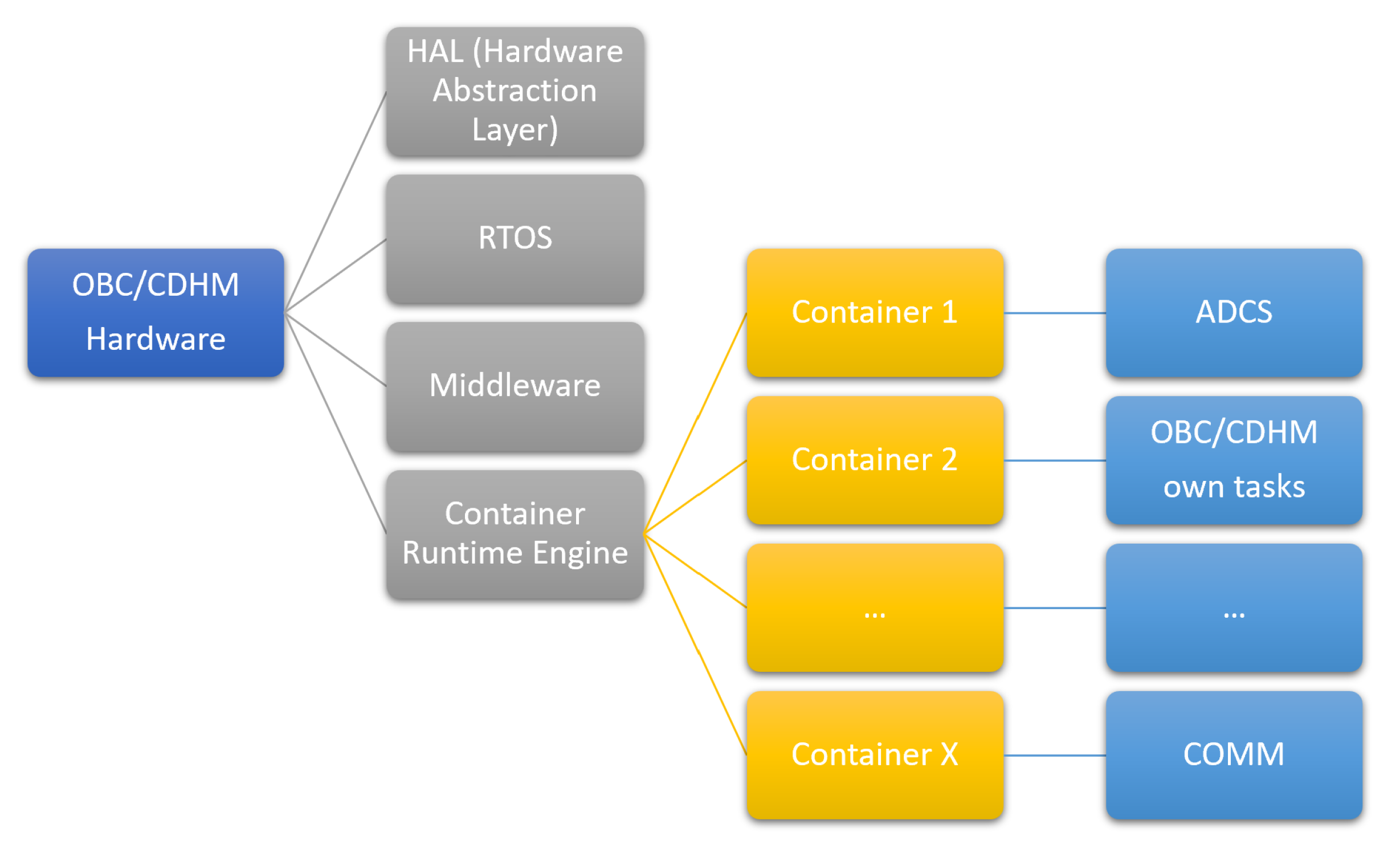
So, what are the proposed new methods of developing CubeSat software with the intent of using SCRUM-like development life-cycle and containerization? They are:
Each container represents either one functional block of the CubeSat (ADCS, EPS, etc.) and/or the separate OBC or payload function, see
Figure 13;
During the development and V&V process of each separate container, the separate team or the team member develops each separate container;
Due to the fact that the containers are cross-platform, the verification and development of each separate container is carried out at the PC and not at the CubeSat hardware.
As the basis of the solution of the container’s engine implementation on the typical CubeSat hardware, the WASM3 interpreter engine was chosen. To be able to run WASM3 on the embedded target of any type, the following minimal infrastructure is to be ported:
The file system: this is required to store containers and be able to upload those for execution;
CLI (command line interface): This allows manipulation with the containers (run, stop, load, etc.) and allows the user to see the system parameters in real-time;
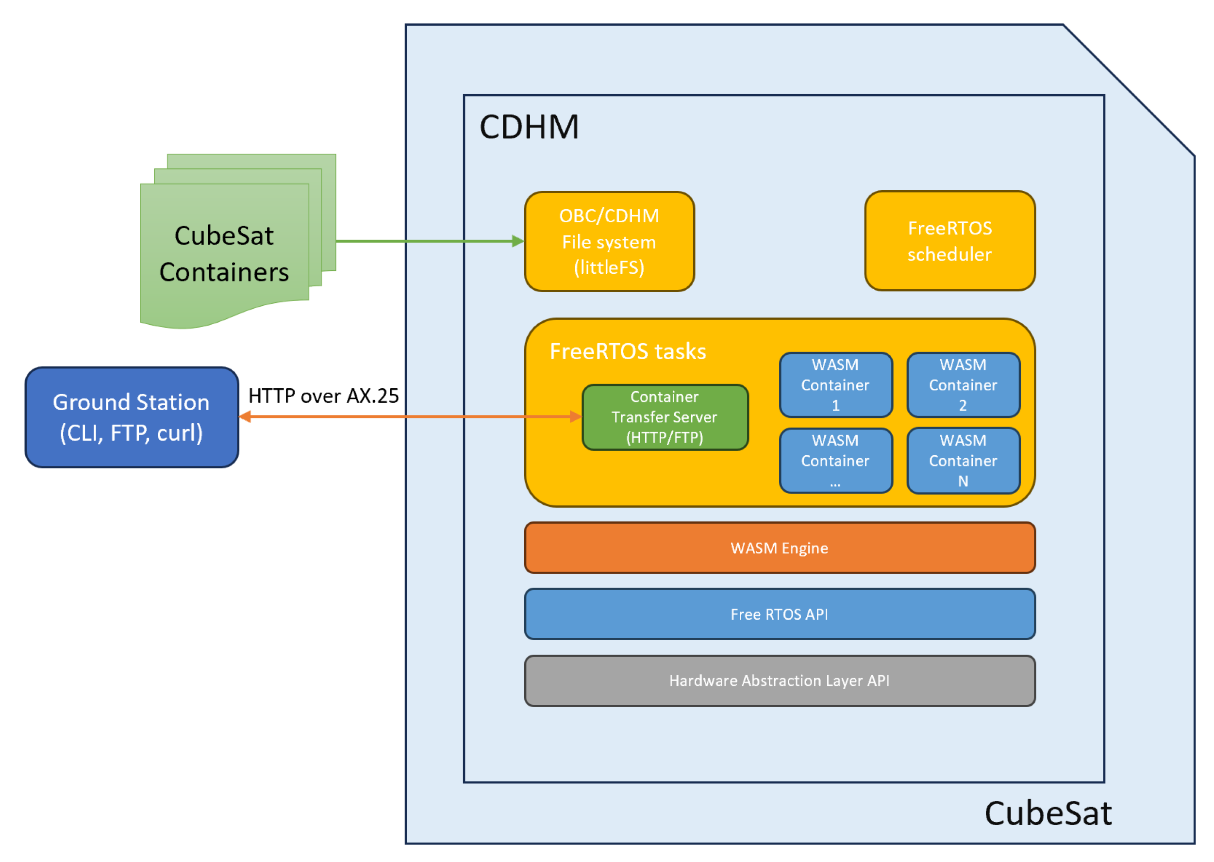
The HTTP server: This will allow for the simple and easy-to-implement OTA (over-the-air) transfer of the container images from a PC to the embedded target (for the communication with the ground stations, AX.25 over HTTP can be used).
As the typical RTOS for the CubeSats is the FreeRTOS by Amazon, the overall architecture of the solution looks as follows (
Figure 14):
2.4. Porting WASM3 to the FreeRTOS-Based Environment
The so-called “porting“ process is a process of developing and adapting a selected piece of software to the selected hardware platform and later-on to the selected RTOS. In our case, there were already embedded ports provided by the community via the GitHub repository. The most relevant existing port for our tasks was the ESP32-IDF one, and it was chosen to be used as a basis for further experimental work in this article. During the porting, the following assumptions were made:
Each container is running as a separate FreeRTOS task;
Containers are running with the priority and scheduling by Round Robin principles as for the FreeRTOS;
The File System is used for the container storage and each container is uploaded to RAM before its use;
The overall porting is carried out by the use of MCU-specific API and FreeRTOS-specific API.
For the file-system implementation, the littleFS embedded low-footprint filesystem was selected. The littleFS is widely used across the industry and is the main implementation candidate for CubeSat use as well. All of the container images are permanently stored on the file system and thus are ready for operation right after the system boot. For the sake of the remote (from the Earth) container upload (
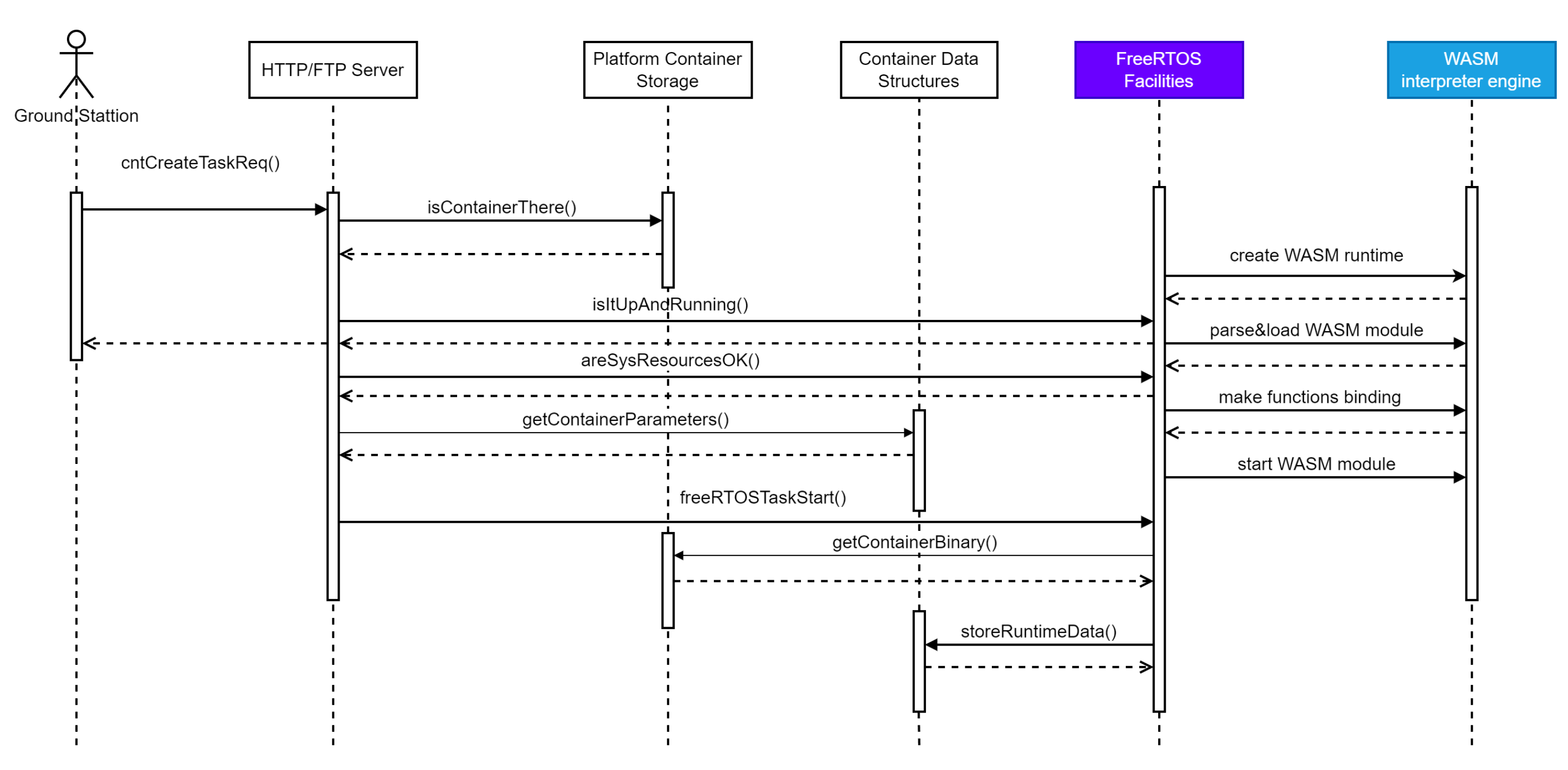
Figure 15), a simplified HTTP/FTP server could be considered and thus used further in this article. Schematically, the container upload and corresponding RTOS task start/stop sequence can be shown as follows:
The sequence diagram above assumes that only one container is running at one single moment of time. If the container already exists on the file system, only the “START” command is required to be altered (See
Figure 16).
In the case of a CubeSat implementation, such a command can arrive via any of the telemetry communication channels or from the system scheduler rather than the container uploading interface only (GroundStation via HTTP/FTP server here).
2.5. Selection of the Hardware Platforms and Algorithms for the Performance Tests
For the performance testing, two platforms were chosen.
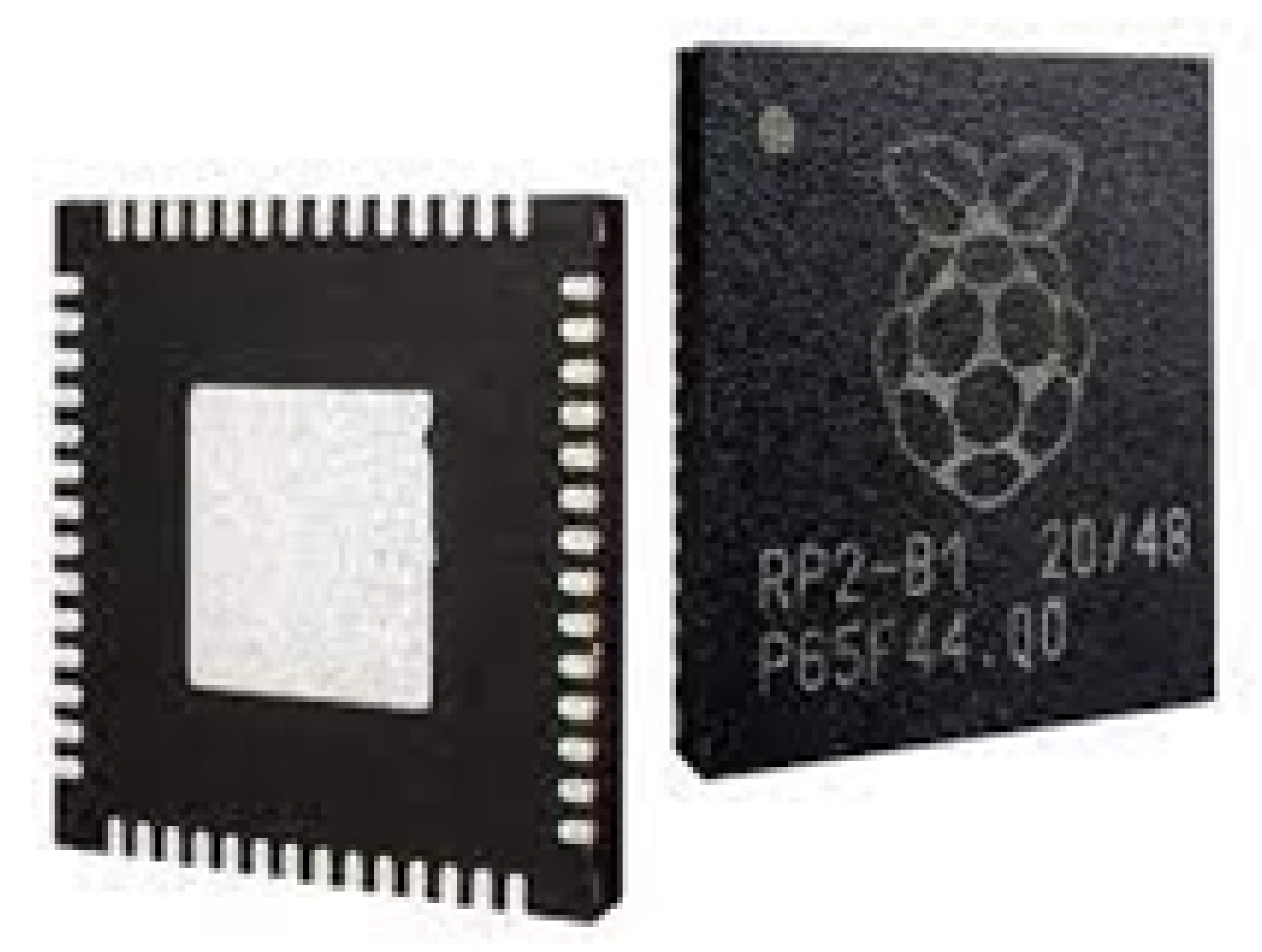
The most popular in the open STEM-like hardware projects is Pi Pico by Raspberry (
Figure 17), based on an RP2040 processor [
40], see
Figure 18. Core type: ARM Cortex-M0+, whose calculation performance is roughly 130 DMIPS.
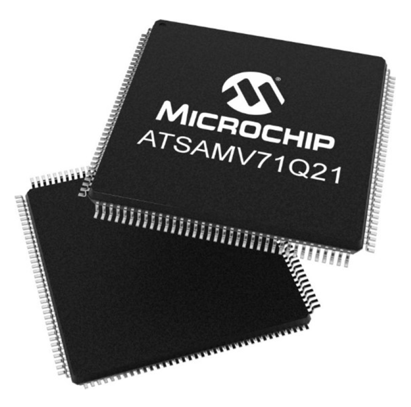
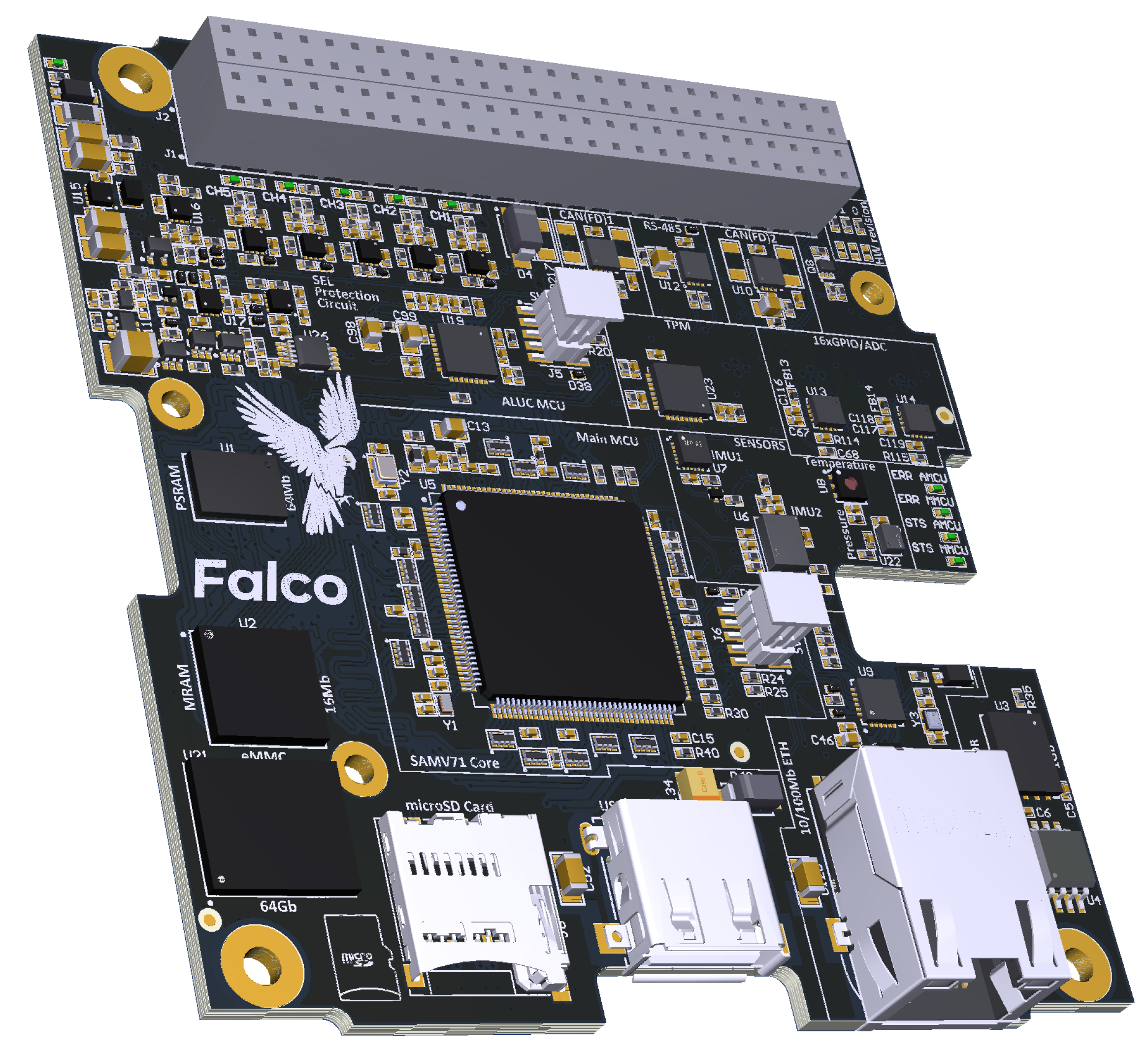
The CDHM platform “Falco SBC 1.0” (see
Figure 19), which was developed by Oleksandr Liubimov [
41] for the Ph.D. thesis, will be used for the upcoming “KhAI-1 spacecraft” 3U CubeSat. The platform is based on the Microchip (Atmel) ATSAMV71Q21 [
42,
43] and shown in
Figure 20. The core type is ARM Cortex-M7 and it’s expected calculation performance is roughly 600 DMIPS.
At the same time, typical algorithms for the embedded software were used for the benchmarking, namely:
For the selected algorithms, the following algorithm’s complexity in “O-notation” is expected:
The main reason for measuring performance here is to see how much overhead the two layers of abstraction (WASM3 and its middleware) bring to the proposed solution. To determine the exact overhead, the same selected algorithms (see
Table 1) were run on a bare metal implementation, i.e., what vendors offer as low-level API + FreeRTOS and on the code written on C/C++ and further WASM3 compiled, where the containers execution engine is also running on FreeRTOS. The following pre-requisites were used for the performance measurements:
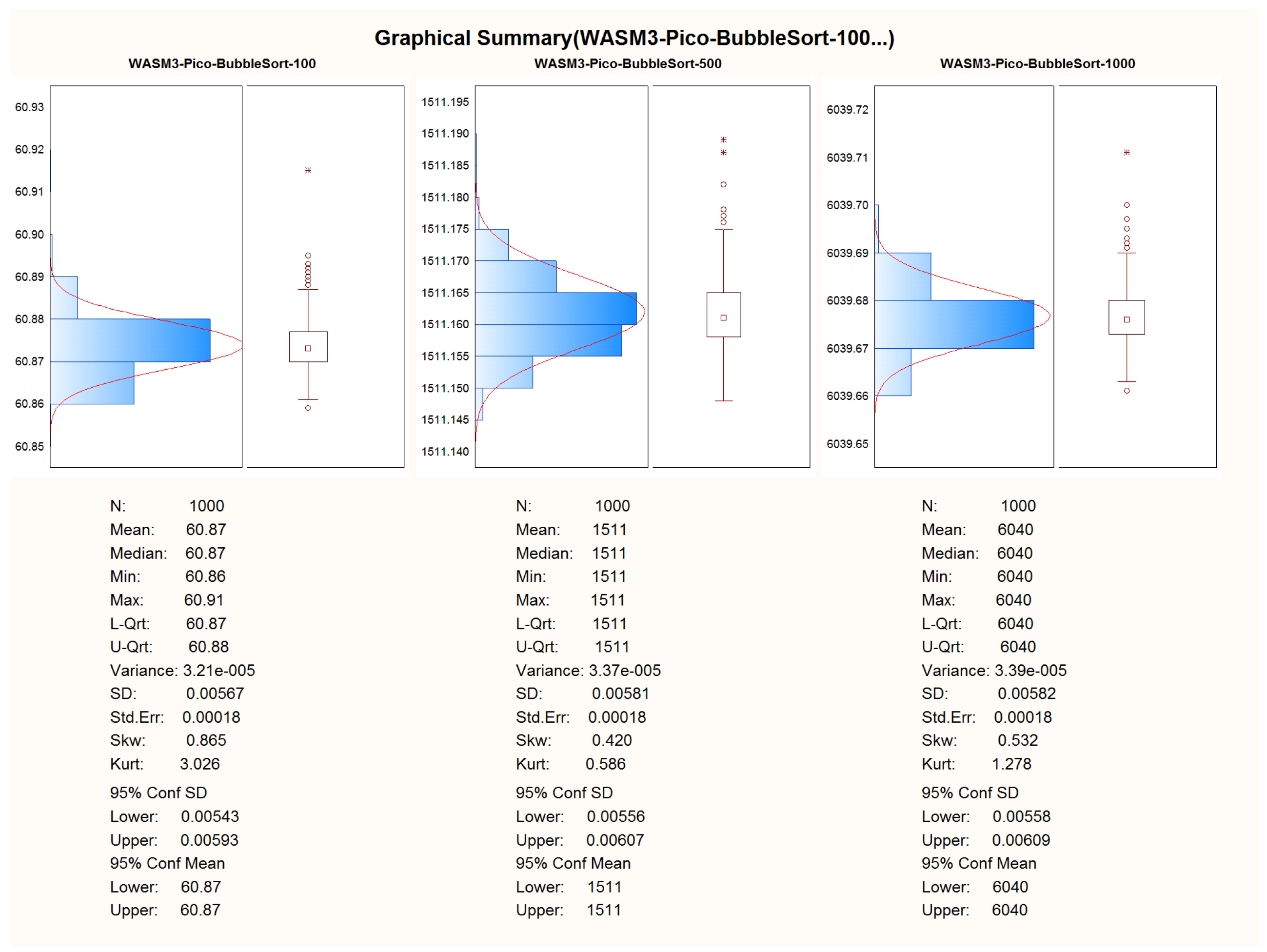
For ensuring repeatability and to be able to properly calculate the S, SD, and AVG times of the computation, 1000 measurements are planned for each experiment;
For each algorithm, 3 different sizes of data will be used. This will be mainly used to prove that the implementation is carried out in a proper manner and O-complexity is followed;
All measurements will be rounded to two digits after the comma;
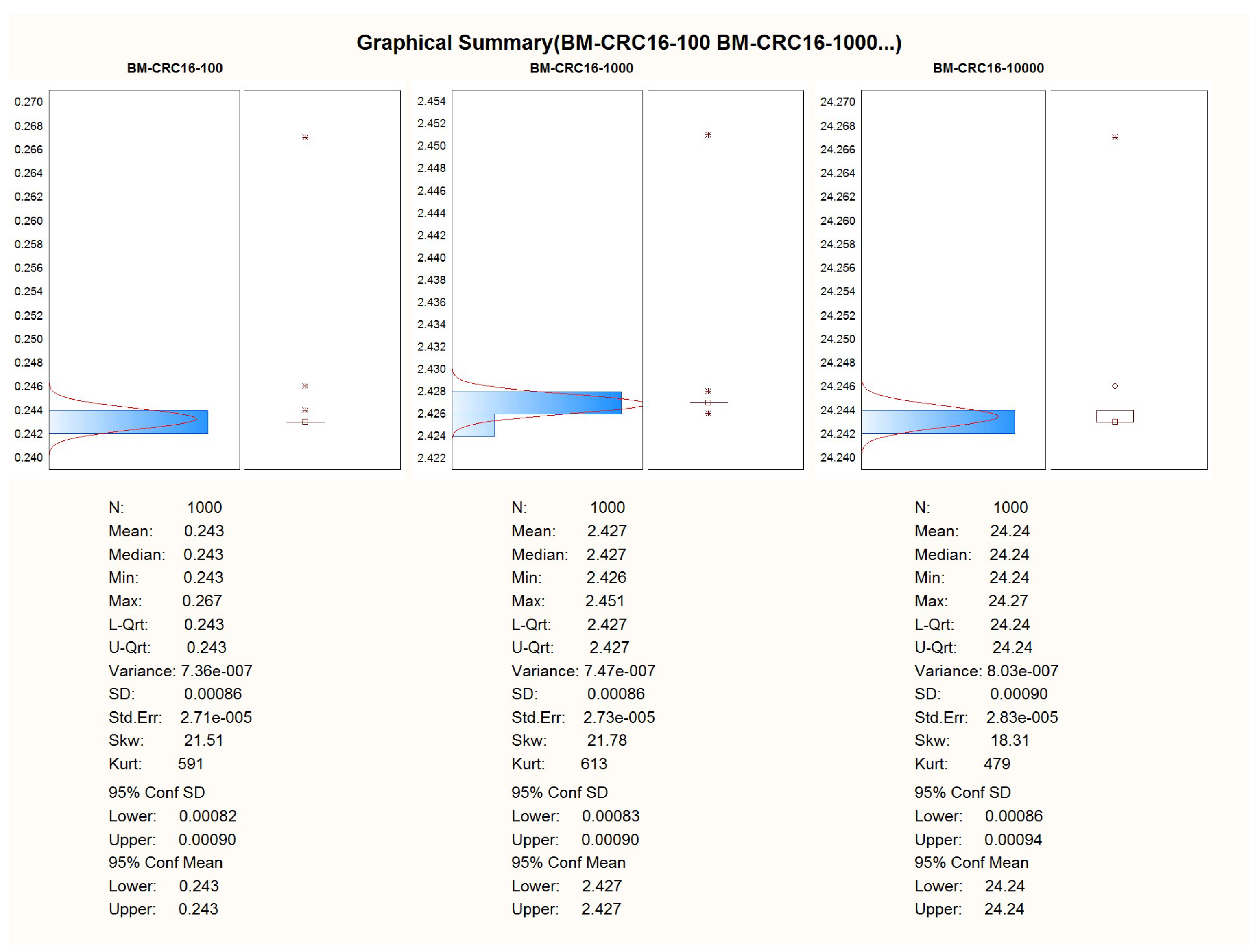
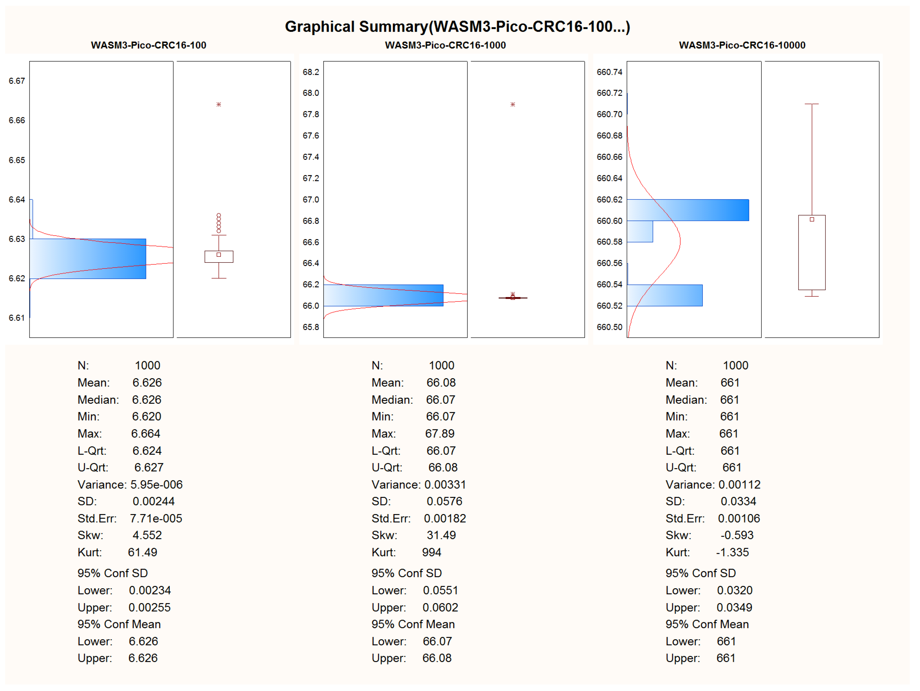
For the CRC-16 algorithm, the sets of 100, 1000, and 10,000, 32-bit signed integers will be used;
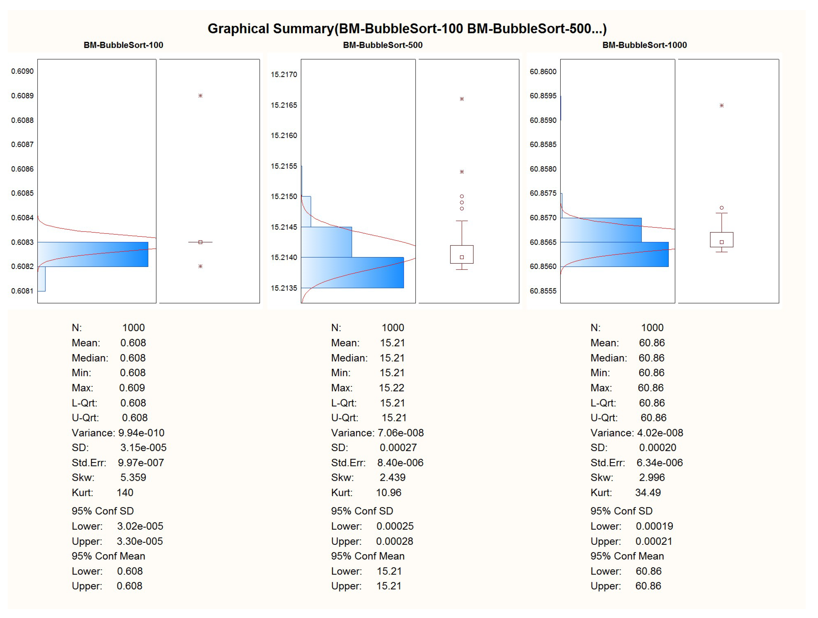
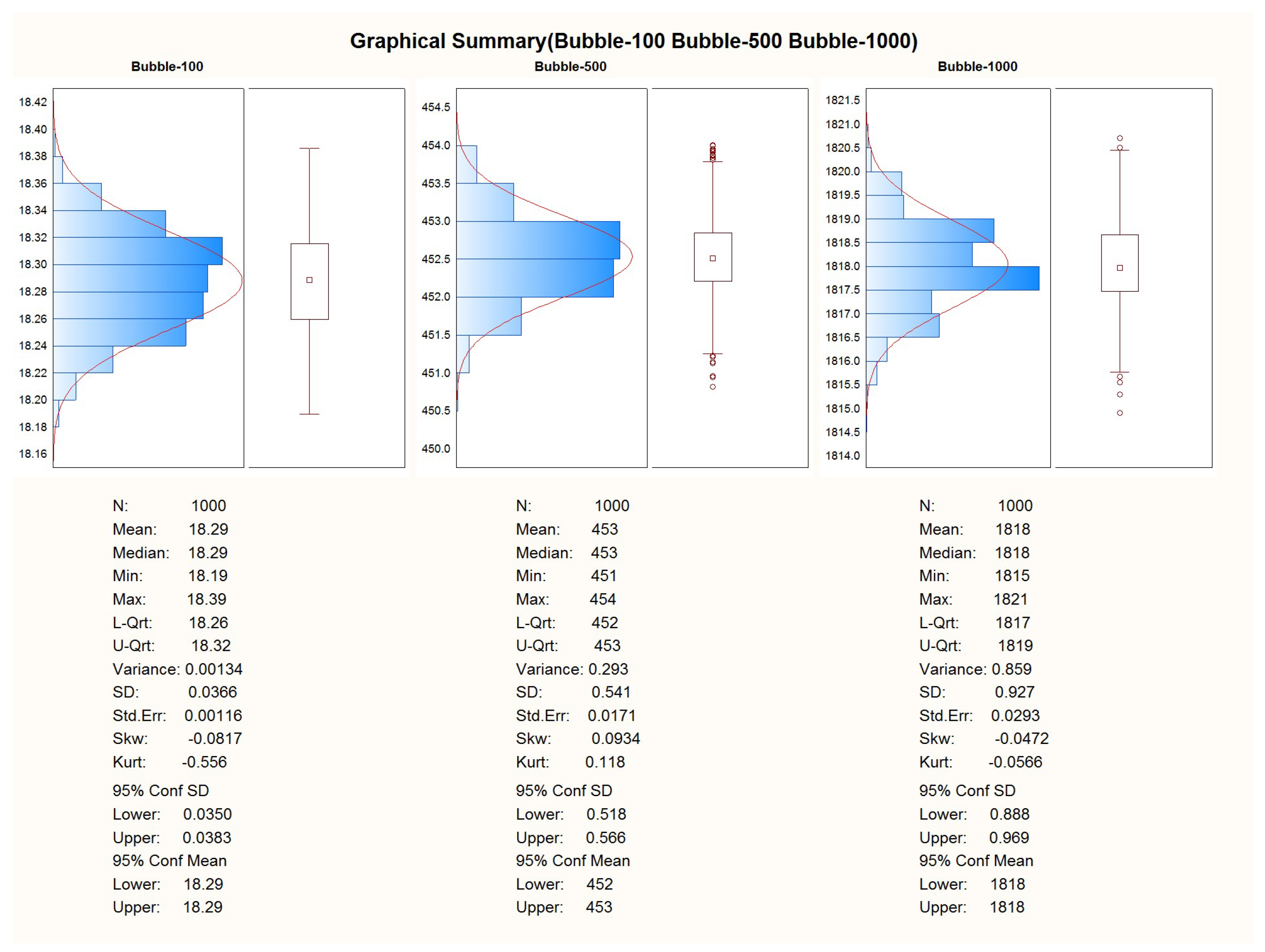
For the bubble sort algorithm, the sets of 100, 500, and 1000, 32-bit signed integers will be used bubble sort sets with the worst possible condition are used—the data vector to be sorted was filled with numbers placed in a back-sorted order.
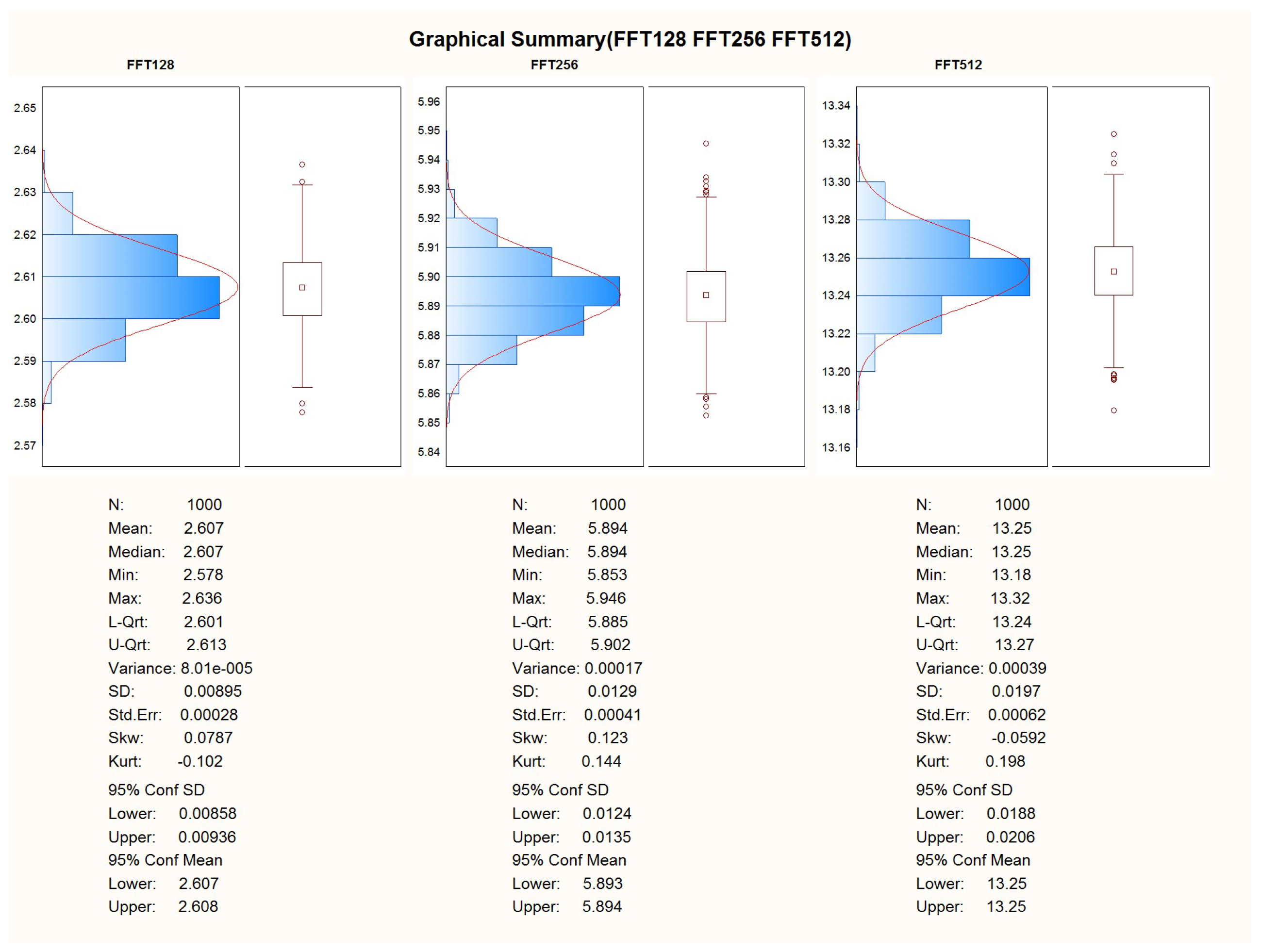
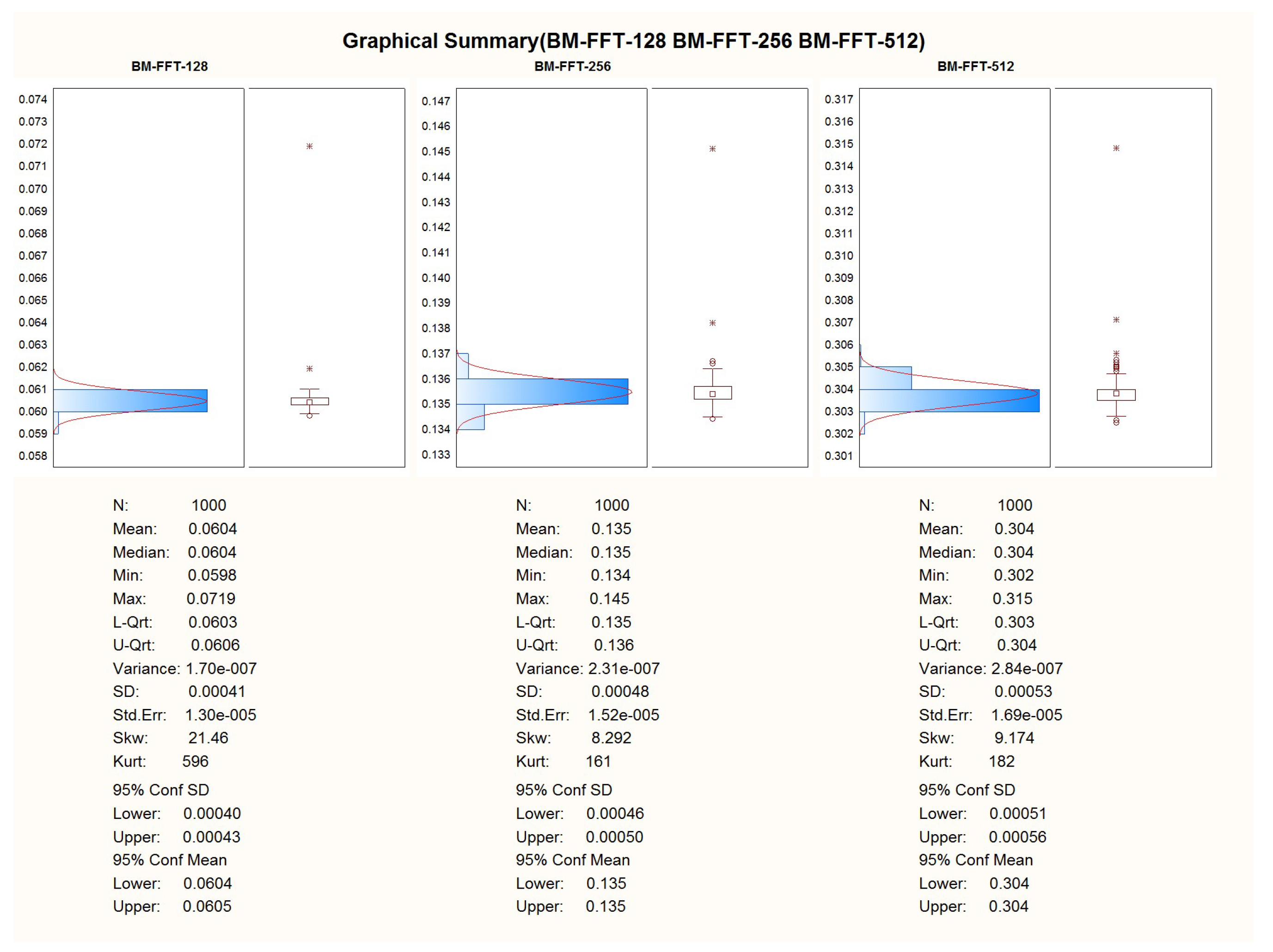
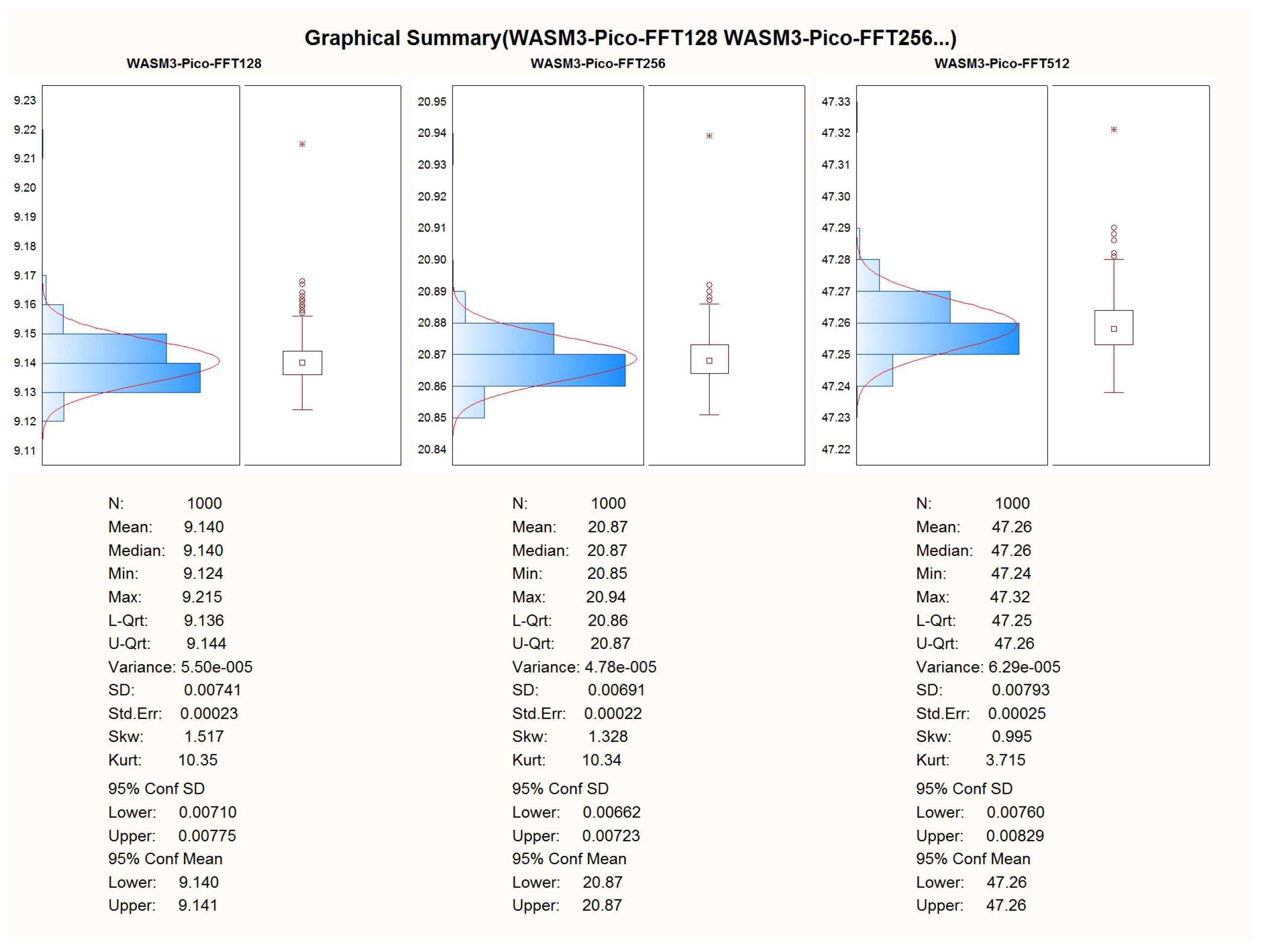
For the Fast Fourier Transform algorithm, the sets of 128, 256, and 512 samples will be used.
3. Results
After the successful adoption of the algorithms to the C and C++ languages, the porting of the code to the WASM3 containers was performed too. To obtain the results, the telemetry channel was used in the look of a hyper-terminal, where the data of the calculation duration were obtained via the regular “printf()” C-function. The duration of the execution of the algorithm was obtained by using the microprocessor’s system timer with a precision of .
The first experiment was made on the entire implementation of pure C language and processor-dependent APIs w/o FreeRTOS and other 3rd party libraries.
The second experiment was carried out with the written C-language container, compiled for the WASM3 container engine, and running under FreeRTOS. The container image was uploaded via the SD-card image and transferred to it from the PC.
Comparative Analysis and Pre-Conclusoins
For the comparison of the two hardware platforms and native C (bare metal) versus WASM3 on the performance of FreeRTOS containers, the test results were chosen on a given number of test data. To provide a good graphical representation of the results (especially for the Native C/bare-metal results), the arithmetic sum of 1000 measurements was used as a basis for comparison.
The following size of the data sets was used for the final performance comparison:
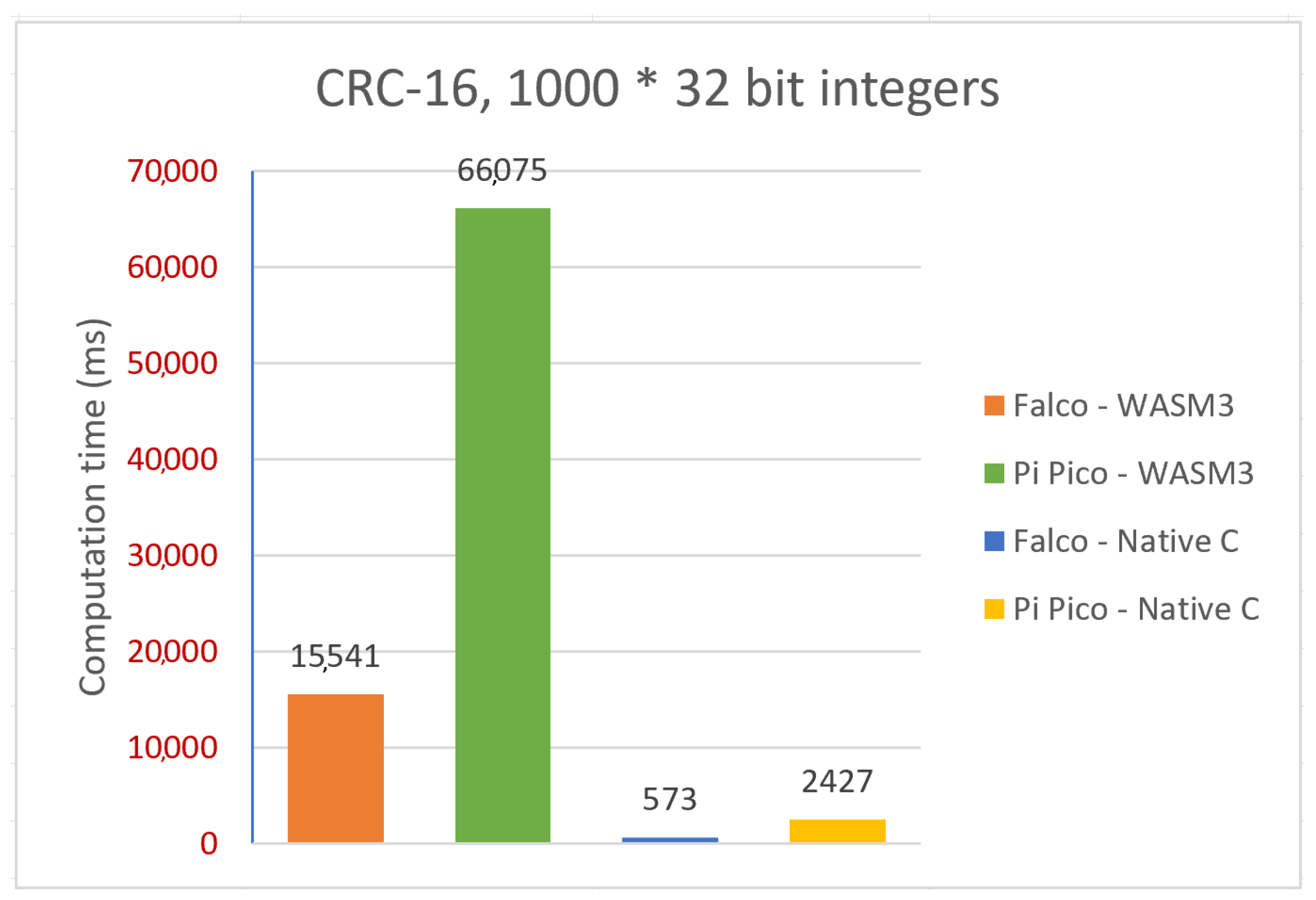
Sum of 1000 measurements for the CRC-16: 1000 × 32-bit signed integers;
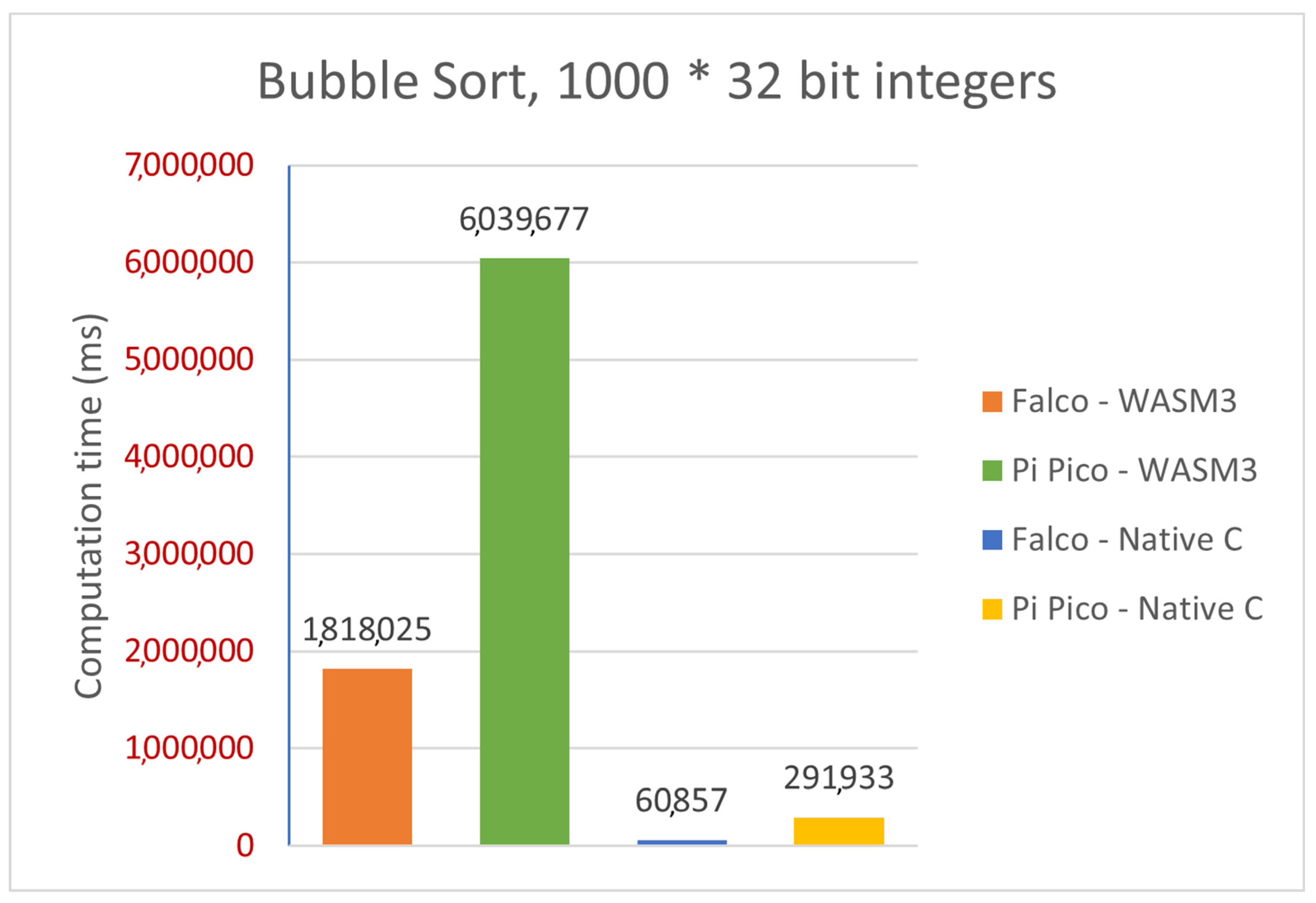
Sum of 1000 measurements for bubble sort: 1000 × 32-bit signed integers;
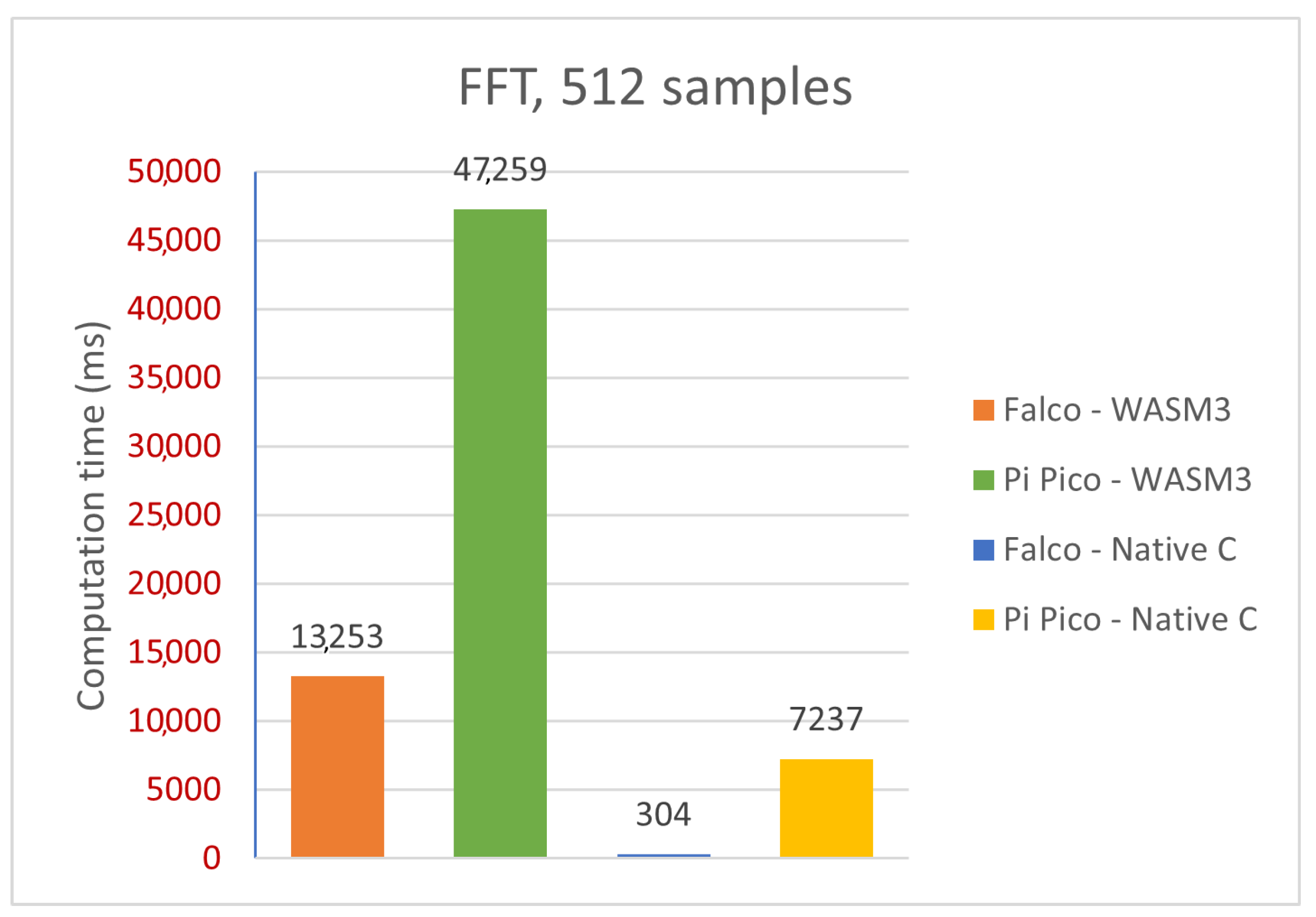
Sum of 1000 measurements for the FFT: 512 samples.
Graphically, such a difference in three selected algorithms could be represented as follows:
Figure 21.
Comparative analysis—CRC-16 (platforms, implementations).
Figure 21.
Comparative analysis—CRC-16 (platforms, implementations).
Figure 22.
Comparative analysis—FFT (platforms, implementations).
Figure 22.
Comparative analysis—FFT (platforms, implementations).
Figure 23.
Comparative analysis—Bubble Sort (platforms, implementations).
Figure 23.
Comparative analysis—Bubble Sort (platforms, implementations).
For further detailed analysis please refer to
Appendix A.
4. Discussion
Porting WASM3 to both hardware platforms and running and executing the tests has brought the authors to the desired results and knowledge.
Performance: It is quite clear from
Table 2 that there is a pretty visible performance difference when running the same algorithms on the native C implementation and the WASM3 implementation. The simple and yet true performance difference is in the range of 30 times, which means that the native C implementation is 30 times faster than the WASM3-one. However, the reader shall remember that it is rather unfair to compare the Native C implementation (which is very close to bare metal digital machine implementation) and the RTOS-based high-level implementation. The obtained difference in performance in the size of two orders (and in some cases one order) is expected and might sound big. However, knowing the typical calculation tasks for the CubeSats, such a performance difference is not a lifesaver and can be accepted.
Implementation Complexity: During the implementation of the algorithms to Native C and WASM3 on the FreeRTOS platforms, it was found that the differences in the required skill set and the speed of implementation are quite different. For the simple algorithms bubble sort and CRC-16, the implementation was rather simple, and thus there was no major difference in the development speed, while for the FFT implementation, it was rather clear that the WASM3 implementation, for which the hardware capabilities are not really taken into account, is much simpler. It was also found that the implementation by the regular undergraduate student is very straightforward even for a student with rather basic programming and data science skills.
Time at the Hardware and Debug: During the implementation of a Native C algorithm, it can be seen that the hardware access was a MUST. It is very typical for embedded software engineers to run the Debug process on a target, even for the hardware-decoupled algorithms we used in the work. At the same time, for the WASM3 implementation, the hardware was not a need as during the development it is clear that the cross-compilation is required to upload the software to the target platform. So, as stipulated in the correct development model research of this article, the demand for the hardware availability is rather low and could help student teams to work simultaneously on the creation and debugging of a CubeSat.
Falco CDHM as the Low-cost and Powerful CubeSat Platform: One of the secondary tasks in this work was to prove that the selected low-cost automotive grade Microchip SAMV71Q21 (Cortex-M7) microprocessor can be a good basement for the student’s CubeSat “KhAI-1 spacecraft” being developed by the National Aerospace University “Kharkiv Aviation Institute”. As the results of this synthetic performance testing demonstrate a substantial performance, the Microchip SAMV71 microprocessor is recommended for future use. It is low-cost, automotive grade and demonstrates outstanding performance.
Future Work: During this research and experiments, quite a few conceptual and practical questions and tasks have been raised. These topics can be stated as follows:
Further development of the ported WASM3 engine so it can be further optimized and support the concurrent container’s execution. This shall allow simple yet powerful orchestration, for instance, on the basis of event-driven architecture (EDA) and/or the use of the “Saga” design pattern;
Further performance optimization shall be carried out, and the real performance penalty overhead sources shall be found;
Research and implement (if required) safe yet performance-optimal hardware low-level access to the microprocessor’s peripherals. The existing implementation of the WASM3 port does not allow that; if there is no easy way to solve it via the WASM3 approach, propose a new one that will be a combination of HAL, FreeRTOS, and WASM3 facilities;
Research low-power modes of such a WASM3 implementation of a CubeSat CDHM as the power consumption requirements for the spacecraft are very constrained;
Research and implement hardware debug facilities that will help to find and fix complex hardware-related issues when the software to be verified is fully “packed” into containers.


