Abstract
An energy-based solution for calculating the buckling loads of partially anisotropic stiffened plates is presented, such as antisymmetric cross-ply and angle-ply laminations. A discrete approach, for the mathematical modelling and formulations of the stiffened plates, is followed. The developed formulations extend the Rayleigh–Ritz method and explore the available anisotropic unstiffened plate buckling solutions to the interesting cases of stiffened plates with some degree of material anisotropy. The examined cases consider simply supported unstiffened and stiffened plates under uniform and linearly varying compressive loading. Additionally, a reference finite element (FE) model is developed to compare the calculated buckling loads and validate the modelling approach for its accuracy. The results of the developed method are also compared with the respective experimental results for the cases where they were available in the literature. Finally, an extended discussion regarding the assumptions and restrictions of the applied Rayleigh–Ritz method is made, so that the limitations of the developed method are identified and documented.
1. Introduction
Structures made of laminated composite materials are recently increasingly used in aerospace, automotive, marine, and other technical applications due to their high values of specific strength and stiffness compared to conventional metallic materials. Compared to unstiffened plates, the fully or partially anisotropic stiffened plates can achieve higher stiffness and strength values with relatively less mass, improving the stiffness-to-weight ratio and making the structure more cost-efficient. Therefore, the ability to calculate the stability of stiffened anisotropic composite plates is of high importance.
During the last few decades, much research work has been published in the field of stability analysis of composite structures. Leissa in [1] provides a thorough overview of the numerous relevant papers available concerning the stability of composite plates and shells. Most of these studies have focused on special cases of un-stiffened plates of various geometric configurations under different loading and boundary conditions. In the present paper, the literature review focuses on buckling solutions achieved with energy methods.
Closed-form exact solutions have been obtained using energy methods for the buckling loads of isotropic [2], specially orthotropic, antisymmetric angle-ply, and antisymmetric cross-ply laminated plates with simply supported edges under uniaxial and biaxial compression, [3,4,5,6]. However, in many practical structural applications, the laminated composite panels may not have a symmetric stacking sequence or comprise layers in directions other than 0°, 90°, and 45°. In these cases, some form of coupling (either normal–shear or bending–extensional) is present. A closed-form solution for such types of laminations is virtually impossible; an approximate semi-analytical method calculating the critical buckling load using the energy approach has been derived by Chamis [7] and proposed by Ashton in [8].
Studies referring to energy-based buckling solutions for unstiffened anisotropic plates are quite limited. Lagace et al. in [9] examined the stability problem of symmetric and unsymmetric laminated plates with various laminations and different types of anisotropy by using the Rayleigh–Ritz method; the effect of extensional-shear, extensional-bending, and extensional–torsion coupling on the critical buckling load was studied. The buckling analysis of anti-symmetrically laminated angle-ply and cross-ply plates with two opposite edges simply supported and the other two free was studied by Sharma [10] using essentially an energy approach. The degrading effect of coupling between in-plane extension and out-of-plane bending was found to be alleviated both by the choice of a suitable thickness ratio of the laminate and/or by increasing the number of layers in a laminate of a given thickness.
Moreover, a potential energy approach has been employed by Chai and Hoon [11] in conjunction with the Rayleigh–Ritz method to study the stability behavior of generally laminated simply supported composite plates, subjected to an in-plane compression load; parametric studies on the combination of the various in-plane loads, i.e., biaxial compression and uniaxial compression plus shear, on practical laminated composite plates were presented and found to be in satisfactory agreement with the reference results. The same author extended the aforementioned stability analysis to generally laminated composite plates with various edge support conditions, [12].
A similar study has been published by Papazoglou et al. In [13]. The authors calculated the critical buckling load, using the Rayleigh–Ritz method, for isotropic, unsymmetric, and antisymmetric unstiffened plates loaded with linearly varying compression and shear loads. The calculated critical buckling loads were found to be in satisfactory agreement with the published reference results. Mondal et al. in [14] investigated the stability behavior of simply supported anisotropic sandwich flat plates subjected to mechanical in-plane loads using an analytical approach (the Rayleigh–Ritz method). The formulation was based on the first-order shear deformation theory and the shear correction factors employed were based on an energy consideration that depends on the lay-up as well as material properties.
In the aforementioned studies, various anisotropic plates were examined with respect to their buckling response using energy approaches. Nevertheless, none of the above cases concerned stiffened plates. A closed-form expression for calculating the buckling solutions for isotropic and orthotropic stiffened plates has been achieved using an energy approach, by [1] and [15], respectively. A study on composite optimization was performed by Herencia et al. [16] using mathematical programming, where symmetric and not anisotropic skin and stiffeners were considered. The buckling loads were computed using closed-form solutions from an energy method (Rayleigh–Ritz). Studies have also been performed in calculating the local buckling of stiffened plates using energy principles. These studies though are found to be limited to symmetric laminations. Characteristic examples are the studies documented in [17,18,19].
The literature has revealed that the global buckling problem of partially anisotropic laminated stiffened plates has not been exhaustively solved, so far, using energy methods. On the contrary, in the last decade, researchers and engineers have attempted to develop analytical solutions for the stability of anisotropic plates by accounting for bending and twisting mechanical coupling; representative works are [20,21,22,23,24,25]. Of the aforementioned, all the studies, except the last one, refer to the global buckling of unstiffened plates. In the last work, [25], the local skin buckling problem of a stiffened plate was resolved analytically for a variety of degrees of material anisotropy by considering the effect of stiffeners (elastic restraints) as boundary conditions on the skin segment.
Currently, the buckling solution for anisotropic stiffened plates is mainly obtained by either performing numerical analysis, usually using the finite element method (FEM), or by considering empirically suitable correction factors for the unstiffened plate solutions. However, during the preliminary design of large-scale stiffened anisotropic structures (e.g., a wing structure) many optimization loops to optimize the structure with respect to buckling resistance are required, [26]. In such cases, where a high number of iteration solutions are required before the optimal geometry is defined, the convergence time is critical. Therefore, the ability to approximate the buckling loads using time-efficient parametric semi-analytical solutions, instead of performing time-consuming FE analyses, is practical and of major importance. So far, this information is limited in the available literature.
To this end, the present work attempts to solve the global buckling problem of partially anisotropic laminated stiffened plates using the Rayleigh–Ritz energy method. The novelty of the current work, with respect to the available literature, is the consideration of material anisotropy in conjunction with the geometry complexity that comes from the stiffeners. Additionally, to express the formulations for considering material and geometry (stiffeners) anisotropy the Rayleigh–Ritz approach has been appropriately modified and extended. The derivations enable the calculation of stiffened plates that are widely used in large-scale structures, and for the reasons mentioned above, such a solution is essential. The approach is an energy-based solution, and it is expressed for specific types of anisotropic skins for various degrees of anisotropy stiffened by orthotropic stiffeners. The presented methodology is based on the classical lamination theory (CLT) assumptions and an extended Rayleigh–Ritz formulation in cases of partially anisotropic stiffened plates. In addition, a reference FE model is developed and used for comparison purposes. Although the developed solution is valid for any plate aspect ratio, the method is demonstrated for square-stiffened plates with simply supported edges under uniform and linearly varying compressive loads. It is worth noting that the analysis assumes that no delamination or debonding (skin-stringer) failures occur during compression, and only buckling is considered. Comparison charts are presented to show the critical buckling loads of plates with different skin laminations and stiffener-to-skin stiffness ratios. The buckling results of the present method are found to be in satisfactory agreement with the respective numerical results. The limitations of the developed approach are discussed in detail.
2. Extension of Rayleigh–Ritz Buckling Solutions for Partially Anisotropic Stiffened Plates
General unsymmetric laminates do not exhibit classical bifurcation behavior. The bending–stretching coupling between membrane and bending will always result in bending deformation and transverse displacement when subjected to an in-plane load, even in the pre-buckling regime. Therefore, a nonlinear analysis is required, even for the elastic pre-buckling region. Nevertheless, a ‘pseudo’ buckling value can be analytically determined using linear plate theory. The critical ‘pseudo’ buckling load is defined as the inverse of a least square fit of the deflection-to-load ratio versus the deflection curve. Although this ‘pseudo’ elastic buckling load does not necessarily correspond to any meaningful location on the load-displacement curve, it can be related to an experimental buckling load determined from a Southwell plot, [9]. Southwell’s method can be accurately applied when deflections are small compared to the plate thickness [27,28].
2.1. Rayleigh–Ritz Formulation of a Stiffened Anisotropic Plate Buckling Problem
Consider the stiffened plate of dimensions (a, b) comprising a partially anisotropic flat skin of thickness (tskin). The plate is reinforced by several orthotropic stiffeners (Nstiffener), as shown in Figure 1. The plate is compressively loaded with a uniform or linearly varying load Nx, in the x-direction. The stiffeners are also loaded with a compressive force F in the same direction.
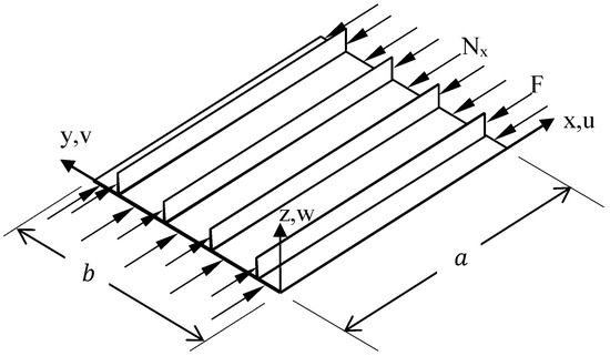
Figure 1.
Geometry of the stiffened anisotropic plate under compressive loading.
The differential equation system, which describes the buckling problem of Figure 1, has no closed-form analytical solution for the case of a fully anisotropic skin. Therefore, the current stiffened plate buckling problem is formulated based on energy principles. More specifically, it is solved by the semi-analytical Rayleigh–Ritz method. Energy formulations are based on energy conservation principles, which require the total potential energy Π of an elastic structural system (i.e., the sum of the work performed by external forces plus the strain energy stored in the structure) to be constant. The potential energy Π of a stiffened plate consists of the un-stiffened plate potential energy Πskin and the stiffeners’ potential energy Πstiffener, as shown in Equation (1). The extension of the generalized Rayleigh–Ritz formulation, currently presented, is based on the consideration of the potential energy of the stiffeners.
The assumptions and restrictions of the CLT are applied in the present formulation. The main assumption of the CLT is that the six components of the laminate strain-tensor are reduced to εx, εy, and γxy by virtue of the Kirchhoff–Love hypothesis that εz, γyz, and γxz are assumed to be zero. Considering small strains and linear elasticity, the stress resultants versus the strains are given by the following equations:
where,
In Equation (2) the coefficients Aij, Bij, and Dij (i, j = 1, 2, and 6) represent the extensional, coupling, and bending stiffness, respectively. The plate middle surface strains and curvatures are denoted by εx, εy, γxy and kx, ky, kxy. The subscript k denotes the kth layer while Nply represents the total number of plies in the laminate. The stiffness of each layer, denoted by Qij, is transformed in the global coordinate system and depends on the layer’s mechanical properties in the material principal axes and orientation angle. Finally, the distance Zk is illustrated in Figure 2.

Figure 2.
Skin laminate cross-section.
It is well known that anisotropic laminates can exhibit coupling between all possible deformations caused by in-plane loads or out-of-plane bending moments. The mechanical coupling depends on the presence of respective terms in the ‘generalized force’ versus ‘generalized strain’ relations of Equation (2), i.e., between the internal force or moment components and in-plane strains or curvatures.
Considering the CLT’s assumptions, the elastic energy Uskin of an anisotropic flat skin can be written as below. It is worth mentioning that this is the generalized expression of the potential skin energy as documented in [29], which considers the extension, coupling, and all bending stiffness matrix terms, as well as the in-plane displacements.
In Equation (4), , , and are the middle-plane displacements of the flat skin.
The longitudinal stiffeners are mathematically modelled as beams attached to the skin. Therefore, the potential energy Ustiffener of the longitudinal stiffener in the deformed state is written as:
In Equation (5), is the apparent modulus of elasticity of the orthotropic stiffener, Iy is the stiffener’s second moment of inertia about the skin’s mid-plane, and Nstiffener is the number of stiffeners considered.
The work (Vskin) carried out upon the application of compressive loading in the x-direction (Nx) on the skin middle plane is:
The work (Vstiffener) carried out during the application of a compressive force (F) acting on the longitudinal stiffeners is:
By assuming that the stiffeners and the skin experience the same strain during deformation, the force F of Equation (7) exerted to the stiffeners is proportional to the in-plane normal load Nx acting on the plate, as shown in Equation (8):
In Equation (8), is the skin modulus of elasticity and Astiffener and tskin are the stiffener’s cross section area and the plate’s thickness, respectively. For the global stiffness matrix of the skin and stiffener refer to Appendix A.
The Rayleigh–Ritz method requires assumptions for the skin’s middle-plane deflection functions , , and . These functions are written in the form of a finite series as shown by Equation (9).
In Equation (9), Amn, Bmn, and Cmn are the un-determined coefficients of the functions and m and n are the number of terms considered in the finite deflection series. The assumed deflections Umn, Vmn and Wmn are functions of the spatial coordinates x and y in a variable separable form, i.e., Xm(x)Yn(y). Additionally, since the buckling shape, Wmn, of a laminated plate under compression is typically described by a single sin-shape in the x-direction, it is assumed that the buckling mode of the stiffened plate is characterized by m buckling half waves in the longitudinal direction. It is also assumed that, in the transverse y-direction, the plate is assumed to buckle in n buckling half waves, as described in [15]. The specific mode shapes in this study are available in Section 2.2.
The stability problem is solved by invoking the principle of stationary total potential energy, which is given by Equation (10).
By substituting the assumed middle-plane deflection functions, given in Equation (9), into Equations (4)–(7) and minimizing the problem, a standard eigenvalue problem is obtained. The resulting critical buckling value Nx is given by Equation (11):
Here, K and L represent the stiffness and loading matrices, respectively, obtained from the deflection functions, and q represents the vector containing the modal amplitudes.
2.2. Boundary Conditions
The considered stiffened plate is assumed to be simply supported. The boundary conditions of such a plate are expressed as follows: at the loaded edges of the skin (i.e., at x = 0 and x = a of Figure 1), it is required that the out-of-plane deflection as well as the bending moment Mx vanish. The mathematical expressions of the conditions are shown in Equations (12) and (15).
The out-of-plane displacement and the bending moment My must attain zero values for the unloaded longitudinal edges of the skin at y = 0 and y = b of Figure 1, as shown in Equations (14) and (15).
The Rayleigh–Ritz method requires the proper selection of the three deflection functions , , and for the flat skin middle-plane displacement. The selected deflection functions must satisfy all geometric and as many static boundary conditions as possible. Considering the skin lamination, the following trigonometric shape functions, Equations (16) and (17), are selected for the buckling solution.
Equation (16) satisfies the edge boundary conditions for an unsymmetric cross-ply skin laminate, while Equation (17) applies to symmetric and antisymmetric angle-ply skin laminates. From the literature, [13], the displacement functions, Equations (16) and (17), are suggested for unsymmetric cross-ply laminates and antisymmetric angle-ply laminates, as they satisfy the simple supported boundary conditions. In cases where different boundary conditions (e.g., free, simply supported, or clamped) are considered for the edges of the plate, different sets of displacement functions must be employed. The characteristic deflection functions for such cases are available in [30].
The buckling load calculation, applying the Rayleigh–Ritz method, of stiffened plates with different skin laminations and stiffener-to-skin stiffness ratios (Equations (4)–(17)) has been scripted in Matlab environment, [31]. The buckling results of the Rayleigh–Ritz method are presented and validated in Section 3 and Section 4 with reference solutions from the literature and numerical analyses.
3. Buckling Solution of Stiffened and Unstiffened Plates with Varying Degree of Anisotropy Using the Rayleigh–Ritz Approach
The validity and accuracy of the applied method is initially demonstrated by comparing the buckling loads of unstiffened anisotropic laminated plates with reference published results. The reference results have been obtained from literature (e.g., [9]). In addition, a reference FE model is developed in ANSYS FE software [32], and an eigenvalue buckling analysis is performed. The SHELL 91 element type was selected for the analysis, since it is an eight-node quadrilateral layered structural shell and can be employed for laminate models. After a detailed convergence study, the element size was found to be 13.8 × 13.8 mm. The numerical analysis provided reference results for comparison, as in most of the examined cases experimental or other semi-analytical results are not available.
Subsequently, partially anisotropic stiffened plates with various stiffener-to-skin stiffness ratios, different skin lamination types, and different loading conditions are solved, such that the accuracy of the extended Rayleigh–Ritz method can be assessed.
3.1. Unstiffened Plates
3.1.1. Uniform Loaded Plates
The first case considered corresponds to simply supported unstiffened plates of different laminations, having the dimensions a = b = 254 mm and tply = 0.134 mm. The material properties of the plate are the following: modulus of elasticity E11 = 130 GPa, E22 = 10.5 GPa; shear modulus G12 = 6 GPa; and Poisson’s ratio ν12 = 0.28. The applied load comprises a uniform compressive load (Nx).
The laminates considered are chosen to cover as many cases of different mechanical coupling in the deformation behavior as possible, excluding laminates that isolate shear–twisting coupling which cannot be constructed. A specially orthotropic laminate is also chosen, as this type of laminate is simple and does not exhibit any of the mechanical couplings mentioned above. Moreover, a fully anisotropic lamination, which exhibits all degrees of mechanical coupling, is also studied for exploring the limitations of the methodology with the selected displacement functions. All examined laminations are presented in Table 1, together with the mechanical coupling that each case shows. It is assumed that 0 degrees is the direction of the fibers, which are aligned to the axial compressive loading.

Table 1.
Laminates considered and associated mechanical coupling.
In Table 2, the buckling loads obtained with the Rayleigh–Ritz method (R–R method) are compared to the respective numerical FE results for different laminations. In addition, Table 2 contains the experimental and analytical reference results from [9]. The number of terms used for the double trigonometric series in the Rayleigh–Ritz formulation is M × N = 30 × 30 after a convergence study was carried out.

Table 2.
Buckling solutions of unstiffened anisotropic plates.
Apart from the predicted buckling load, the corresponding buckling mode is also investigated for the examined cases. It is found out that the experimentally or numerically obtained buckling modes match with the respective modes of the Rayleigh–Ritz approach, for all cases. Indicative but representative comparisons between the numerically and semi-analytically obtained buckling modes for the laminations [02/452/02/−452/02] and [06/606] are presented in Figure 3 and Figure 4.
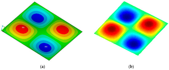
Figure 3.
Buckling modes of the [02/452/02/−452/02] plate. (a) FE model (ANSYS), (b) R–R method.
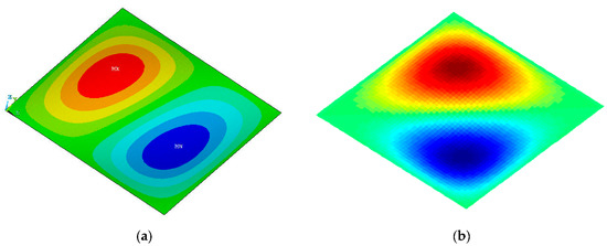
Figure 4.
Buckling mode of the [06/606] plate calculated. (a) FE model (ANSYS), (b) R–R method.
It may be observed from Table 2 and Figure 3 and Figure 4 that in most cases the results of the applied Rayleigh–Ritz method appear to have satisfactory agreement with most of the presented numerical FE results, as well as with the results found from the literature.
The possible causes of the discrepancies observed in some cases may be classified into two categories: (a) experimental errors and (b) inaccuracies due to the choice of the deflection functions and/or the degree of convergence (terms M, N). More specifically, the four first examined laminations, separated by the bold line in Table 2, do not have a high degree of mechanical coupling between extension, shear, bending, and twisting behavior. Therefore, the deflection functions used for unsymmetric/antisymmetric laminations (Equations (16) and (17)) satisfy the required boundary conditions. As a result, the discrepancy between the buckling loads of the applied Rayleigh–Ritz method and the respective numerical/experimental results is low. On the contrary, in cases of fully anisotropic plates, such as [06/606], where a high degree of mechanical coupling exists, the boundary conditions are partially satisfied; according to the selected trigonometric functions of Equations (16) and (17), only the out-of-plane displacements obtain zero values in the boundaries. Therefore, higher differences are observed between experimental, numerical and the Rayleigh–Ritz method’s results for fully anisotropic plates.
Regarding the mode shapes of the plates, it can be concluded that the modes obtained numerically generally match the respective semi-analytical modes. Despite this, a second observation reveals a mismatch between the obtained numerical and semi-analytical mode for the plate with lamination [06/606]. This can be justified by considering the extensional–twisting and bending–twisting mechanical coupling that this specific lamination demonstrates.
3.1.2. Linear Varying Loaded Plates
In this section, the Rayleigh–Ritz method is applied to unstiffened plates with linearly varying compressive loads for validation purposes. Equation (6) is modified accordingly to Equation (18), to mathematically express the linearly varying load.
where Equation (18) may represent various forms of linearly varying loads depending on the values of the coefficient φ. Specifically, φ = 0 represents a uniform load, 0 < φ < 1 represents a trapezoidal load, and φ = 1 represents a triangular load.
The examined case refers to a simply supported plate loaded with a triangular load, which has the following geometrical characteristics: aspect ratio a/b = 2 and width-over-thickness ratio b/tskin = 100, i.e., it is a thin laminate. The laminate stacking sequence is [0/90/90/0/0] with lamina material properties of E11/E22 = 10, G12/G22 = 0.5, and Poisson’s ratio ν12 = 0.25. The buckling load obtained for this case is compared to the respective results from [13]. Once again, the number of terms used for the double sine series in the Rayleigh–Ritz approach is M × N = 30 × 30.
It may be observed from Table 3 that the three first modes obtained utilizing the Rayleigh–Ritz method are in satisfactory agreement with the reference results from [13] and the results from the developed FE model. It can hence be concluded that the developed Rayleigh–Ritz method is validated for unstiffened plates with different anisotropic laminations and various geometric characteristics.

Table 3.
Buckling load comparison between the R–R solution, FE model, and reference results [13] for the case of a linearly varying loaded plate.
3.2. Stiffened Plates
3.2.1. Stiffened Plates with One Stiffener
Most of the literature studies of stiffened plates concern isotropic or orthotropic plates and only a few of them refer to anisotropic stiffened plates. Moreover, none of the buckling solutions for stiffened anisotropic plates employ energy methods. A characteristic example is [33], which numerically analyzed, without employing energy solutions, unsymmetric laminated stiffened plates with respect to buckling.
In this section, an investigation of the applicability and efficiency of the Rayleigh–Ritz method in the case of anisotropic plates is performed. The buckling loads obtained from the extended Rayleigh–Ritz method are validated by comparing them to the respective results from the literature and from the numerical analysis (developed FE model).
The examined skin of the stiffened plate has dimensions, a stacking sequence, and material properties identical to those described in Section 3.1.1. One single stiffener is attached to the skin with the same lamination as the skin. The height of the stiffener is hstiffener = 9tskin. Two different loading conditions are assumed for the plate: (a) uniform load and (b) linear varying load. The stiffener is unloaded and loaded for the aforementioned loading case.
In Table 4 and Figure 5 the buckling loads and the mode shapes for the case of [0/90/90/0/0], which has only extensional–bending mechanical coupling, are presented. The skin is assumed to be uniformly or linearly loaded, while the stiffener is unloaded. The results of the extended Rayleigh–Ritz method are compared with the numerical FE results and the results retrieved from the literature, [33].

Table 4.
Buckling load comparison between R–R solution, FE model, and the reference results of [33] work for the case of a [0/90/90/0/0] laminated stiffened plate with unloaded stiffener.
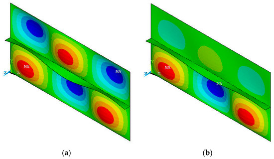
Figure 5.
(a) Mode shape comparison for the case of a [0/90/90/0/0] laminated stiffened plate with unloaded stiffener. (a) Uniform loaded skin, (b) linearly varying loaded skin.
A satisfactory agreement may be observed between the results obtained with the extended Rayleigh–Ritz method and those calculated numerically in Table 4. The selected trigonometric deflection functions can satisfy the boundary conditions of the skin and providing an accurate calculation of the critical buckling load for a uniformly and linearly varying loaded skin.
The stiffener is modelled as a beam attached to the skin; hence, it is assumed that when global buckling occurs, the stiffener follows the same deflection shape as the skin. Therefore, this assumption does not introduce any significant errors in the case of stiffened plates. On the contrary, by comparing the results obtained from the developed FE model and those obtained from the Rayleigh–Ritz method with the results of [33], higher differences are observed. It is believed that the buckling solution referred to [33] corresponds to a higher buckling mode compared to the buckling mode presently calculated.
The buckling problem of the partially anisotropic stiffened plate considered previously is solved again, now considering a loaded stiffener. In Table 5 the buckling load obtained from the Rayleigh–Ritz method is once again compared to the present reference FE solution.

Table 5.
Buckling load comparison between the R–R solution and FE model for the case of a [0/90/90/0/0] laminated stiffened plate with a loaded stiffener.
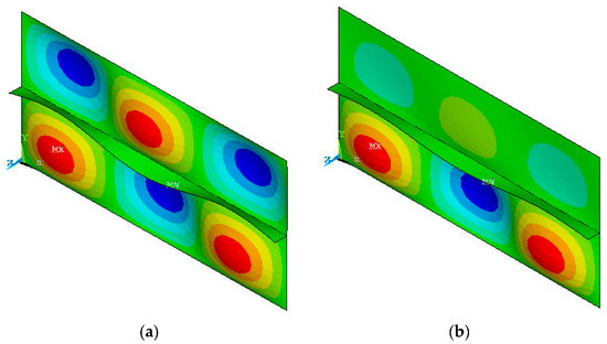
Figure 6.
(a) Mode shape of a [0/90/90/0/0] laminated stiffened plate with a loaded stiffener. (a) Skin uniformly loaded, (b) skin linearly varying loaded.
It can be observed from Table 5 that in the case of a uniformly loaded skin, the difference between numerical and semi-analytical (extended Rayleigh–Ritz method) results is approximately 6%. However, when the skin is loaded under a linearly varying load, the difference for the same geometric characteristics increases to 9.5%. This error probably arises from the varying skin forces, which introduce an error to Equation (8), since the strain that the skin and the stiffener experience is not the same.
3.2.2. Plates Stiffened with Multiple Stiffeners
The applicability of the Rayleigh–Ritz method is further examined for the interesting cases of plates braced with multiple stiffeners. A systematic parametric study of the problem of simply supported square stiffened plates of 500 mm edges with various skin laminations, stiffened by multiple stiffeners, is performed.
The examined plates are braced by 10 equidistant blade stiffeners of 0.536 mm thickness and varying heights. The height of the stiffeners is assumed to vary, such that the ratio of stiffener-bending stiffness-to-skin-bending stiffness ranges from 0% to approximately 100%, depending on the case examined. The five laminate stacking sequences presented in Table 2 are considered for the skin. The skin and stiffener material properties are those described in Section 3.1.1 for the cases of linearly loaded unstiffened plates. The stiffeners are assumed to have an orthotropic configuration of [0/90]s lamination with a ply thickness of 0.134 mm.
In Figure 7, the calculated critical buckling loads are presented and compared to the respective results obtained from the developed reference FE model.
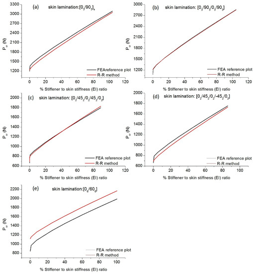
Figure 7.
Critical buckling loads versus percentage stiffener-to-skin stiffnesses for different skin laminations.
Characteristic buckling modes obtained from the parametric study are presented in Figure 8.
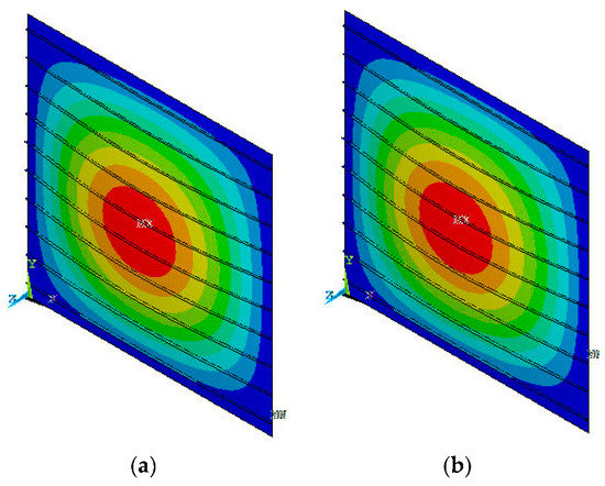
Figure 8.
Global buckling of stiffened plates with skin lamination. (a) [02/452/02/452/02], (b) [06/606].
It can be observed from Figure 8 that as the stiffener-to-skin stiffness ratio increases the critical buckling load increases as well. Furthermore, by comparing the results from the extended Rayleigh–Ritz method with the respective numerical (FE) results, a good correlation is observed. Regarding the first four laminations, considered in Figure 8, the boundary conditions of the skin are satisfied by the selected deflection functions.
However, in the last case of [06/606], where a high degree of mechanical coupling exists, the boundary conditions are not fully satisfied by the selected trigonometric functions of Equations (13) or (15). Therefore, an error is introduced to the examined cases of this lamination, leading to unconservative results for all the stiffener-to-skin stiffness ratios.
Finally, it can be concluded that the degree of convergence, which is dependent on the number of terms M, N of the deflection functions, is satisfactory when M and N are 30, considering the result’s accuracy, the solution time, and computational effort.
4. Conclusions
The systematic comparison between the results of the present method and the respective semi-analytical, experimental results, from the literature, as well as the numerical results from the FE analyses revealed the following: (a) a satisfactory accuracy of the extended Rayleigh–Ritz method, especially for the cases of unstiffened and stiffened anisotropic plates with a low degree of extensional-bending mechanical coupling; (b) the results indicate that as the degree of mechanical coupling increases, the boundary conditions are only partially satisfied by the selected trigonometric functions, and the discrepancy with respect to the reference results and mode shape increases. Furthermore, in all the investigated cases, the required effort and solution time are significantly lower when the Rayleigh–Ritz solution is applied compared to the respective FE analysis. As a result, the extended Rayleigh–Ritz approach is worth trying in the conceptual and preliminary design phases of large-scale structures, where multiple iterations for determining the members’ sizing are required. Overall, this method must be applied with caution and always by considering the degree of material anisotropy of the plate, employing suitable deflection functions, and allowing small deflections compared to the plate thickness to obtain meaningful results.
Special care must be paid to estimating the buckling load of plates made of variable stiffness composite (VSC) materials using the Rayleigh–Ritz method. It is challenging due to difficulties in selecting appropriate deflection functions that accurately represent plate deformation while satisfying the often complex boundary conditions of VSC materials, [34]. In these special cases, it is suggested to employ the Rayleigh–Ritz method in combination with an isogeometric analysis (IGA) to accurately model the highly anisotropic behavior of composite materials, but challenges may still arise in selecting the appropriate deflection functions that satisfy the boundary conditions, [35,36]. In general, engineers must carefully select the deflection functions and accurately model the material properties of composite plates to optimize the design and improve their buckling resistance and performance.
Author Contributions
Conceptualization, D.G.S. and G.N.L.; Methodology, D.G.S. and G.N.L.; Software, D.G.S.; Validation, D.G.S.; Formal Analysis, D.G.S.; Investigation, D.G.S.; Resources, D.G.S.; Data Curation, D.G.S.; Writing—Original Draft Preparation, D.G.S.; Writing—Review & Editing, D.G.S. and G.N.L.; Visualization, D.G.S.; Supervision, G.N.L.; Project Administration, G.N.L.; Funding Acquisition, G.N.L. All authors have read and agreed to the published version of the manuscript.
Funding
This research was funded by the EU research project “Advanced Low-Cost Aircraft Structure” (ALCAS) grant number 516092.
Data Availability Statement
Not applicable.
Acknowledgments
The authors wish to acknowledge AIRBUS-UK for the support of this research.
Conflicts of Interest
The authors declare no conflict of interest.
Appendix A
The global stiffness matrix of the skin and stiffeners is given below.
where z is the eccentricity of the stiffeners, which corresponds to the distance between the skin midsurface and stiffener elastic centroid.
References
- Leissa, A.W. Buckling of composite plates. Compos. Struct. 1983, 1, 51–66. [Google Scholar] [CrossRef]
- Timoshenko, S.P.; Geere, J.M. Theory of Elastic Stability, 2nd ed.; McGraw-Hill Book Company: New York, NY, USA, 1961. [Google Scholar]
- Narita, Y.; Leissa, A.W. Buckling studies for simply supported symmetrically laminated rectangular plates. Int. J. Mech. Sci. 1990, 32, 909–924. [Google Scholar] [CrossRef]
- Jones, R.M. Mechanics of Composite Materials; Taylor & Francis: New York, NY, USA, 1999. [Google Scholar]
- Whitney, J.M. Structural Analysis of Laminated Anisotropic Plates; Tecnomic Publishing AG.: Lancaster, PA, USA, 1987. [Google Scholar]
- Iyengar, N.G.R. Structural Stability of Columns and Plates; Ellis Horwood: West Sussex, UK, 1988. [Google Scholar]
- Chamis, C.C. Buckling of Anisotropic Composite Plates. J. Struct Div. (ASCE) 1969, 95, 2119–2139. [Google Scholar] [CrossRef]
- Ashton, J.E. Approximate Solutions for Unsymmetrically Laminated Plates. J. Compos. Mater. 1969, 3, 189–191. [Google Scholar] [CrossRef]
- Lagace, P.A.; Jensen, D.W.; Finch, D.C. Buckling of unsymmetric composite laminates. Compos. Struct. 1986, 5, 101–123. [Google Scholar] [CrossRef]
- Sharma, S.; Iyengar, N.G.R.; Murthy, P.N. The buckling of antisymmetrically laminated angle-ply and cross ply plates. Fibre Sci. Technol. 1980, 13, 29–48. [Google Scholar] [CrossRef]
- Chai, G.B.; Hoon, K.H. Buckling of generally laminated composite plates. Compos. Sci. Technol. 1992, 45, 125–133. [Google Scholar] [CrossRef]
- Chai, G.B. Buckling of generally laminated composite plates with various edge support conditions. Compos. Struct. 1994, 29, 299–310. [Google Scholar] [CrossRef]
- Papazoglou, V.J.; Tsouvalis, N.G.; Kyriakopoulos, G.D. Buckling of unsymmetric laminates under linearly varying biaxial in-plane loads combined with shear. Compos. Struct. 1992, 20, 155–163. [Google Scholar] [CrossRef]
- Mondal, B.; Ganapathi, M.; Kalyani, A. On the elastic stability of simply supported anisotropic sandwich panels. Compos. Struct. 2007, 80, 631–635. [Google Scholar] [CrossRef]
- Mittelstedt, C. Explicit analysis and design equations for buckling loads and minimum stiffener requirements of orthotropic and isotropic plates under compressive load braced by longitudinal stiffeners. Thin Wall. Struct. 2008, 46, 1409–1429. [Google Scholar] [CrossRef]
- Herencia, J.E.; Weaver, P.M.; Friswell, M.I. Initial sizing optimisation of anisotropic composite panels with T-shaped stiffeners. Thin Wall. Struct. 2008, 46, 399–412. [Google Scholar] [CrossRef]
- Khosravi, P.; Sedaghati, R. Local buckling and mode switching in the optimum design of stiffened panels. AIAA J. 2008, 46, 1542–1548. [Google Scholar] [CrossRef]
- Bisagni, C.; Vescovini, R. Analytical formulation for local bucking and post-buckling analysis of stiffened laminated panels. Thin Wall. Struct. 2009, 47, 318–334. [Google Scholar] [CrossRef]
- Stamatelos, D.G.; Labeas, G.N.; Tserpes, K.I. Analytical calculation of local buckling and post-buckling behavior of isotropic and orthotropic stiffened panels. Thin Wall. Struct. 2011, 49, 422–430. [Google Scholar] [CrossRef]
- Fazzolari, F.A.; Carrera, E. Advanced variable kinematics Ritz and Galerkin formulations for accurate buckling and vibration analysis of anisotropic laminated composite plates. Compos. Struct. 2011, 94, 50–67. [Google Scholar] [CrossRef]
- Baucke, A.; Mittelstedt, C. Closed-form analysis of the buckling loads of composite laminates under uniaxial compressive load explicitly accounting for bending–twisting-coupling. Compos. Struct. 2015, 128, 437–454. [Google Scholar] [CrossRef]
- Rasheed, H.; Al-Masri, R.; Alali, B. Closed form stability solution of simply supported anisotropic laminated composite plates under axial compression compared with experiments. Eng. Struct. 2017, 151, 327–336. [Google Scholar] [CrossRef]
- York, C.B.; Muller de Almeida, S.F. Effect of bending-twisting coupling on the compression and shear buckling strength of infinitely long plates. Compos. Struct. 2018, 184, 18–29. [Google Scholar] [CrossRef]
- Vescovini, R.; Dozio, L.; D’Ottavio, M.; Polit, O. On the application of the Ritz method to free vibration and buckling analysis of highly anisotropic plates. Comp. Struct. 2018, 192, 460–474. [Google Scholar] [CrossRef]
- Mantzaroudis, V.; Stamatelos, D. An approximate closed-form buckling solution for the local skin buckling of Stiffened Plates with Omega Stringers: The case of Antisymmetric Cross-Ply and Angle-Ply Laminations. In Structures; Elsevier: Amsterdam, The Netherlands, 2020; Volume 28, pp. 1196–1209. [Google Scholar]
- Stamatelos, D.G.; Labeas, G.N. Towards the design of a multispar composite wing. Computation 2020, 8, 24. [Google Scholar] [CrossRef]
- Southwell, R.V. On the analysis of experimental observations in problems of elastic stability. Proc. R. Soc. 1932, 135, 601–616. [Google Scholar]
- Donnell, L.H. On the Application of Southwell’s Method for the Analysis of Buckling Tests; McGraw Hill: New York, NY, USA, 1938; Vol. Stephen Timoshenko 60th Anniversary Volume. [Google Scholar]
- Lekhnitskii, S.G. Anisotropic Plates; Gordon and Breach: New York, NY, USA; London, UK; Paris, France; Montreaux, Switzerland; Tokyo, Japan; Melbourne, Australia, 1968. [Google Scholar]
- Reddy, J.N. Mechanics of Laminated Composite Plates and Shells Theory and Analysis, 2nd ed.; CRC Press: Boca Raton, FL, USA, 2004; p. 831. [Google Scholar]
- MATLAB, Version 7.0; The MathWorks, Inc.: Natick, MA, USA, 2008.
- ANSYS®. Mechanical Release, Version 14.0; ANSYS Inc.: Canonsburg, PA, USA, 2007.
- Kumar, Y.V.S.; Mukhopadhyay, M. A new finite element for bucking analysis of laminated stiffened plates. Compos. Struct. 1999, 46, 321–331. [Google Scholar] [CrossRef]
- Chen, B.; Zeng, Y.; Wang, H.; Li, E. Approximate Bayesian assisted inverse method for identification of parameters of variable stiffness composite laminates. Compos. Struct. 2021, 267, 113853. [Google Scholar] [CrossRef]
- Hu, H.; Yu, T.; Lich, L.V.; Bui, T.Q. Functionally graded curved Timoshenko microbeams: A numerical study using IGA and modified couple stress theory. Compos. Struct. 2020, 254, 112841. [Google Scholar] [CrossRef]
- Wu, Y.; Liu, J.; Zhang Sh Huang, H. A novel dynamic isogeometric reanalysis method and its application in closed-loop optimization problems. Comput. Methods Appl. Mech. Eng. 2019, 353, 1–23. [Google Scholar] [CrossRef]
Disclaimer/Publisher’s Note: The statements, opinions and data contained in all publications are solely those of the individual author(s) and contributor(s) and not of MDPI and/or the editor(s). MDPI and/or the editor(s) disclaim responsibility for any injury to people or property resulting from any ideas, methods, instructions or products referred to in the content. |
© 2023 by the authors. Licensee MDPI, Basel, Switzerland. This article is an open access article distributed under the terms and conditions of the Creative Commons Attribution (CC BY) license (https://creativecommons.org/licenses/by/4.0/).