Article

A Novel Computational Model for Traction Performance Characterization of Footwear Outsoles with Horizontal Tread Channels

1
Centre for Biomedical Engineering, Indian Institute of Technology (IIT), Delhi 110016, India
2
Department of Biomedical Engineering, All India Institute of Medical Science (AIIMS), Delhi 110029, India
*
Author to whom correspondence should be addressed.
Computation 2023, 11(2), 23; https://doi.org/10.3390/computation11020023
Submission received: 25 November 2022 / Revised: 23 January 2023 / Accepted: 29 January 2023 / Published: 2 February 2023
(This article belongs to the Special Issue Application of Finite Element Methods)

Abstract

:
Slips and falls are among the most serious public safety hazards. Adequate friction at the shoe–floor contact is necessary to reduce these risks. In the presence of slippery fluids such as water or oil, the footwear outsole is crucial for ensuring appropriate shoe–floor traction. While the influence of flooring and contaminants on footwear traction has been extensively studied across several outsole surfaces, limited studies have investigated the science of outsole design and how it affects footwear traction performance. In this work, the tread channels of a commonly found outsole pattern, i.e., horizontally oriented treads, was varied parametrically across the widths (i.e., 2, 4, 6 mm) and gaps (i.e., 2, 3, 4 mm). Nine outsole designs were developed and their traction, fluid pressures, and fluid flow rates during slipping were estimated using a mechanical slip testing and a CFD-based computational framework. Outsoles which had wider tread (i.e., 6 mm) surfaces showed increased slip risks on wet flooring. Outsoles with large gaps (i.e., 4 mm) exhibited increased traction performance when slipped on wet flooring (R2 = 0.86). These novel results are anticipated to provide valuable insights into the science of footwear traction and provide important guidelines for the footwear manufacturers to optimize outsole surface design to reduce the risk of slips and falls. In addition to this, the presented CFD-based computational framework could help develop better outsole designs to further solve this problem.

1. Introduction

Accidents caused by slipping and falling are prevalent in both the workplace and recreational activities. In 2020, slips and falls accounted for more than 950,000 fatal and non-fatal injuries in the workplace, hospitals, industries, and homes in the US and UK combined [1,2]. In addition to this, slip-related incidences have led to lower limb problems such as dislocations and tears causing the workers to take hospitalization leave, resulting in more than 15 days of delay in work [2,3]. Predominantly, slips occur due to a decrease in the available coefficient of friction (ACOF) between the footwear and the floor [4,5]. Hence, in order to reduce these injuries, it is vital for the public and the shoe industry to understand the function of footwear and its characteristics to ensure adequate shoe–floor friction.
Reportedly, a high correlation exists between a decrease in shoe–floor friction and an increase in slip hazards [6,7]. Previous research has demonstrated the ACOF as a reliable measure to estimate the effectiveness of footwear against slips [8,9,10,11,12]. Slip testers or tribometers are typically utilized to quantify the ACOF. In the past, various studies have employed a wide variety of slip testers with diverse operating mechanisms [13,14,15,16,17,18,19,20]. Recently, Chanda et al. [11] quantified the traction performance of several footwears including slip-resistant and non-slip-resistant. It was found that only a few shoes were able to cross the threshold ACOF of 0.3, above which the slip severity reduces significantly. Hence, traction testing of a footwear, before its use, is essential for the safety of the wearer.
Footwear ACOF has been found to be affected by the outsole’s tread design, contact area, material, and shore hardness. Specifically, the outsole design features such as, tread inclination, width, gaps, and depth have been reported to majorly affect the ACOF [10,19,21,22,23]. Yamaguchi et al. [24], reported the influence of tread features on the ACOF as a property of treads to dissipate the excess fluid through the tread channels during fluid-contaminated slipping. In another study by Li et al. [25], variations in the tread widths of the outsole having a vertically oriented tread pattern were studied in dry and fluid-contaminated conditions, and significant differences in the ACOF outcomes were observed. These studies indicate the importance of understanding the science of the outsole features and the way they may affect footwear friction.
The performance of outsole treads in draining the excess fluid during slipping has been reported to be critical in determining the traction performance of a footwear in fluid-contaminated conditions [26,27]. Footwear friction is also significantly reduced by variables such as the outsole wear and the presence of contaminants such as water or any viscous fluid (e.g., oil) [28,29]. In a recent study by Beschorner et al. [26], the effect of treaded and untreaded outsoles on the fluid pressures during slips were studied. The study reported high correlation between fluid pressures and slip risk. In another study by Hemler et al. [27], a tapered-wedge bearing method was implemented to determine the fluid forces during slipping in new and worn footwear. The study concluded that increasing fluid pressures over the worn region led to reduced tractions. To date, only a few studies have estimated the traction performance of footwear using computational methods [30,31]. Additionally, a key gap exists in the literature with respect to the study of fluid flow and pressures across footwear outsoles, and the understanding of the relationship between outsole tread geometry and the induced footwear friction.
In this work, a commonly used tread pattern with horizontal orientation (i.e., orthogonal to the slipping motion axis) was systematically modified to study its effect on footwear traction. The fluid pressures, and fluid flow rates during slipping, were estimated using a CFD computational framework, and traction was quantified through mechanical slip testing. A range of correlations were computed between the footwear tread parameters and traction to understand the relationships. The findings from this pioneering work are anticipated to clarify the effect of outsole tread parameters on footwear traction in dry and wet conditions, and advance the knowledge of footwear tread designing. The framework along with the outcomes are anticipated to help the footwear industry in developing shoes with enhanced traction properties.

2. Materials and Methods

The footwear outsole geometry selected in this work included treads based on the impressions of an original footwear. The selected design had horizontally oriented treads, orthogonal to the slip motion. Footwear outsole attributes such as tread geometry and shore hardness were measured using a depth gauge (Precision Instruments, Delhi, India) and a durometer (Precision Instruments, India), respectively. The depth gauge had a sensitive vertical probe and a fixed stand. The fixed stand was kept at the treads and the vertical probe was placed on the baseline of the outsoles. For Shore A hardness measurement, the durometer had a similar device setup with a sensitive probe and fixed stand. The probes were kept on the treads for 30 s before the measurements were recorded.
The considered variables were measured over the heel region measuring 50 mm from the posterior point, and have been reported previously to be sufficient in determining the traction performance of shoes [5,7,10,29,32]. The material of the outsole was identified as polyurethane with a Shore A hardness of 50. The tread measurements were recorded and imported in a CAD modeling software (SolidWorks, Dassault Systèmes, Vélizy-Villacoublay, France). The original outsole had a tread width of 2 mm with an interval gap of 2 mm (Figure 1). Furthermore, the widths and gaps were modified systematically with an interval of 2 mm and 1 mm, respectively, with the depth maintained as a constant (i.e., 2 mm). Table 1 lists the different parametrical modifications conducted on the tread design.
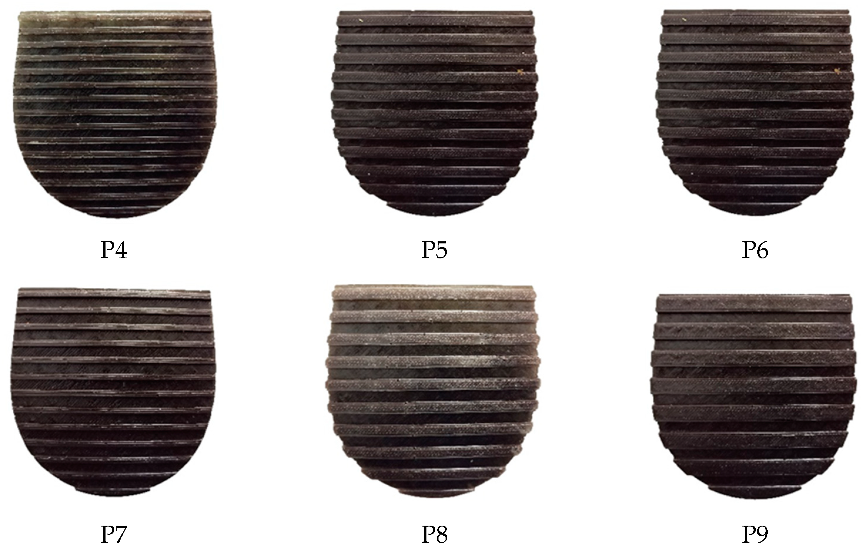
To fabricate the outsoles, molds of nine parametrically generated models were 3D printed using an enclosed 3D printer (Voxelab Aquila, Flashforge, Jinhua City, Zhejiang Province, China). The 3D printer was a bouden-type enclosed printer and had a bed size of 220 × 220 mm. To print the PLA molds, an extrusion temperature of 200 °C and bed temperature of 60 °C was applied. As the outsole treads included intricate corners, the molds were printed at a low extrusion and speed (i.e., 25 mm/s). The molds were filled with a hydrophobic pourable liquid silicone (LSR 130, Chemzest Products, India). The silicone was left to dry for 7 h and was taken out from the respective molds. A two-part polyurethane was poured into the negative silicone molds and left to cure for 48 h. The employed polyurethane material had a Shore A hardness of 50 to match the original footwear material properties. After the removal of the developed outsoles, extra edges were trimmed and re-measured for their dimensions. Additionally, the resulting shore hardness was confirmed using the durometer. Figure 2 represents the nine footwear outsole designs.
The traction performance was quantified by employing a whole-shoe portable biofidelic mechanical slip testing device [33] (Figure 3), which was developed based on the international standard ASTM F2913-19 [34]. Previous studies have developed and implemented the device based on the mentioned ASTM standard [11,22,35,36,37]. The outsole was attached to a footwear and the footwear was further attached over the shoe, last. A shoe–floor angle of 17 ± 2° was fixed during the testing. Furthermore, a normal force of 250 ± 25 N and slipping speed of 0.5 m/s were implemented based on extensive human slipping studies and footwear slip testing investigations [5,10,11,22]. Slip testing was performed for the nine developed outsoles across a common flooring in dry and wet conditions. The surface roughness of the flooring was measured as 3.5 µm, using a digital surface profilometer (Precision Instruments, India). The device included a movable linear probe which was placed at five different locations over the testing surface. The device measured the peak to valley roughness and displayed an average value digitally. A single flooring was considered based on the observations by Chanda et al. [11], which reported generalizable ACOF outcomes in several dry and fluid-contaminated flooring and, hence, helped in reducing the overall time and effort. The ACOF values were estimated within 200 ms from the start of slip simulation, once the normal force reached 250N. For each test condition, five trials were conducted and the average results were reported. The vertical force (Fvertical) and the horizontal force (Fshear), during slipping simulation, were measured dynamically. The ratio of these dynamic quantities were used to calculate the ACOF (Equation (1)).
ACOF = F shear F vertical
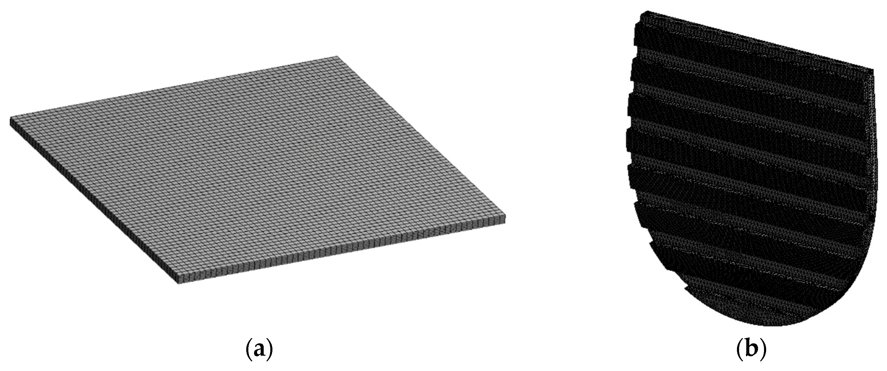
The numerical simulation of the realistic slipping mechanism was modelled on ANSYS 2019 R3 (Ansys Inc., Canonsburg, PA, USA). The simulations were performed in two parts, which included the deformation of the treads due to application of the normal load and fluid flow simulations to simulate wet slip testing. Firstly, each outsole CAD model was computationally warped up to 50 mm by 17°. Optimal test parameters (i.e., 50 mm metric and 17° bend angle) were used to evaluate the traction effectiveness of the footwear, in line with similar literature studies [22]. To mimic the material properties of polyurethane, the outsoles were modeled with a hyperelastic neo-Hookean material model [38,39]. A contact pair was applied between the outsole and the ground to simulate the contact interaction. Due to its accuracy and ease in convergence [40,41,42], 10-node SOLID 187 tetrahedral elements were used for the analysis. For the simulation, a normal load of 250 N was applied over the outsole and the deformed models were imported to ANSYS Fluent, to characterize the fluid–structure interaction. To select the optimal mesh size, five distinct mesh refinements were applied for the mesh convergence study. The meshed models were solved for the maximum pressure and maximum velocity. The mesh which produced low variations (i.e., below 5%) in the result was selected as the optimal mesh size. The selected mesh size was then applied to other outsole models. In addition to this, the orthogonal quality of over 80% of the meshed cells was ensured above 0.9. To evaluate the drainage performance of the treads, the realistic slipping motion was simulated using computational fluid dynamics (CFD). The outsole model P1 was generated with 465,525 elements, P2 with 254,653 elements, P3 with 312,124 elements, P4 with 874,983 elements, P5 with 274,855 elements, P6 with 564,835 elements, P7 with 897,546 elements, P8 with 352,225 elements, and P9 with 287,865 elements. Figure 4 represents the generated meshes for the surface and the outsole.
The wet slipping motion was characterized using a steady state and incompressible turbulent flow regime. The Fluent solver was pre-programmed with the Reynolds-averaged continuity equation for the conservation of mass (Equation (2)) and the Reynolds-averaged Navier-Stokes equation for the conservation of momentum (Equation (3)). The turbulent flow regime was applied with a k-epsilon model to further develop the framework. Equations (4) and (5) represent the k-epsilon turbulence model where, P k is the turbulence production due to viscous forces (Equation (6)), μ t is the turbulence viscosity (Equation (7)), and C μ , C ε 1 , σ k , σ ε , and C ε 2 are constants. To model these conditions (i.e., confined and surface flow), the constants in the equation i.e., C μ , C ε 1 , and C ε 2 were applied with values 0.0845, 1.42, and 1.68, respectively, which are widely used standard converged values.
u x + v y = 0
ρ d u d t + ρ ( u d u d x + v d u d y ) = d p d x + μ 2 u ¯ + f t u r b ¯
ρ k t + ρ · ( U k ) = · [ ( μ + μ t σ k ) k ] + P k ρ ε
ρ k t + ρ · ( U ε ) = · [ ( μ + μ t σ ε ) ε ] + ε k ( C ε 1 P k C ε 2 ρ ε )
where,
P k = μ t U · ( U + U T ) 2 3 ( · U ( 3 μ t · U + ρ k )
μ t = C μ ρ k 2 ε
The surface beneath the outsole (i.e., floor) was modelled as a stationary surface with no slip boundary condition. The surface roughness of the wall was applied as 3.5 µm, mimicking the actual experimental conditions. The measured surface roughness was modified as equivalent to sand grain roughness based on a previous study [43] (Equation (8)).
y R = 0.978   R a
The fluid speed of 0.5 m/s was provided as the inlet. The pressure–velocity interaction was based on the Semi-Implicit Method for Pressure Linked Equations (SIMPLE) algorithm and the modeling of pressure and momentum was performed with a second order and second order upwind, respectively. For the scaled residuals, 1 × 10 6 was used as the convergence criterion. Figure 5 represents the computational domain and the boundary conditions used to simulate the wet slipping condition.
The ACOF of nine outsoles were estimated across the flooring in dry and water-contaminated conditions using the mechanical slip testing device. The induced pressures and mass flow rates were quantified using the developed computational framework. The quality of correlations of tread width with the ACOF in both dry and wet conditions, tread width with the fluid pressure and mass flow rate, tread gaps with the ACOF in both dry and wet conditions, and tread gap with the fluid pressure and mass flow rate, was quantified using the correlation coefficient (R2). For this work, 0.5 > R2 was considered insignificant, 0.5 < R2 < 0.7 was considered as moderate, and R2 > 0.7 as strong correlations [11].

3. Results

3.1. Traction Performance of Footwear Outsoles

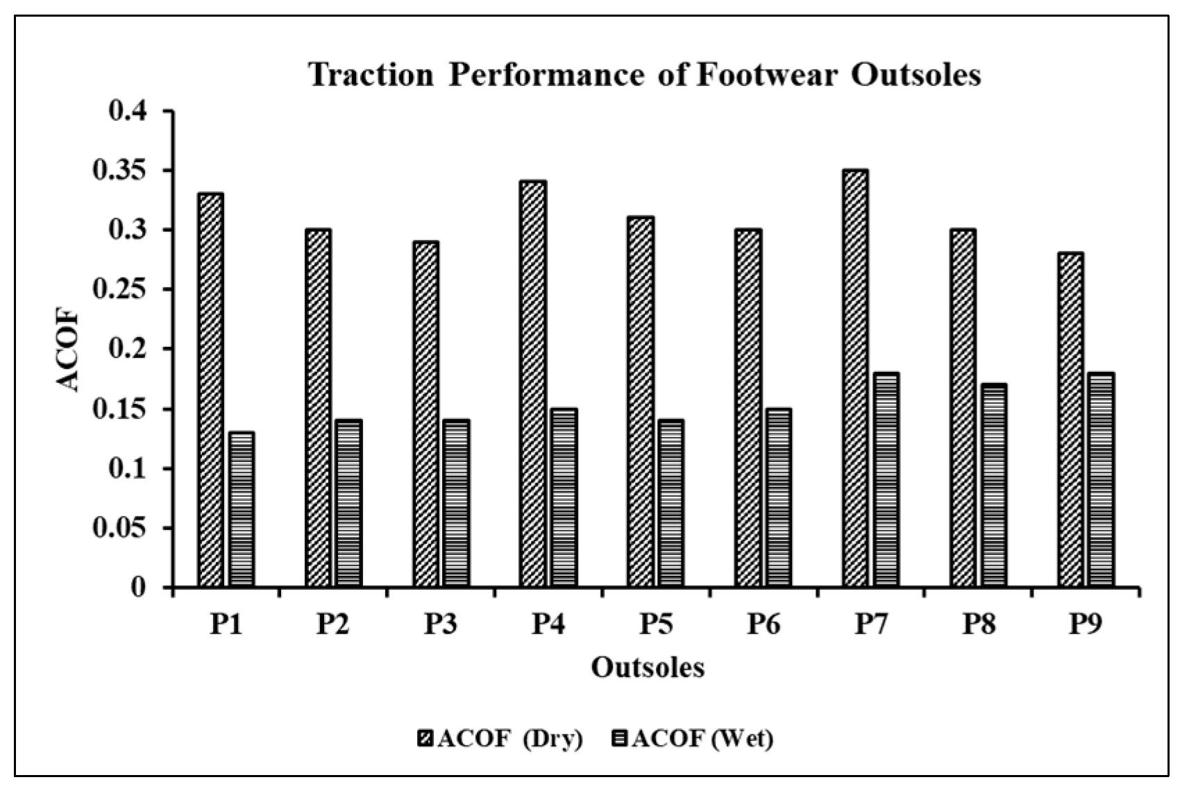
The ACOF of the outsoles, when tested mechanically in dry and wet conditions, ranged from 0.13 to 0.35 (Figure 6). In dry slip testing, the ACOF values varied from 0.28 to 0.35. P1, P4, and P7 showed similar and higher ACOF values compared to the other outsoles. The maximum difference in the ACOF in these outsoles was 0.01 where, P7 showed the highest ACOF (i.e., 0.35) followed by P4 (i.e., 0.34), and P1 (i.e., 0.33). P5 experienced a reduction of 12% in the ACOF compared to P7; whereas, P2, P6, and P8 showed an identical ACOF reduction of over 14%. P9 and P3 showed the lowest ACOF values of 0.28 and 0.29, respectively, compared to other outsoles. In wet slip testing, the ACOF values ranged from 0.13 to 0.18. Out of all the outsoles, P7 and P9 exhibited the highest ACOF value of 0.18 when slip tested on wet flooring. Additionally, P8 performed similarly to these outsoles with a maximum difference of 0.01 in the ACOF outcomes. Outsoles P2, P3, and P5 showed a similar ACOF with a reduction of 22% as compared to P7. P4 and P6 exhibited an ACOF of 0.15; whereas, P1 exhibited the lowest ACOF of 0.13.

3.2. Fluid Pressure and Mass Flow Rates across the Outsoles

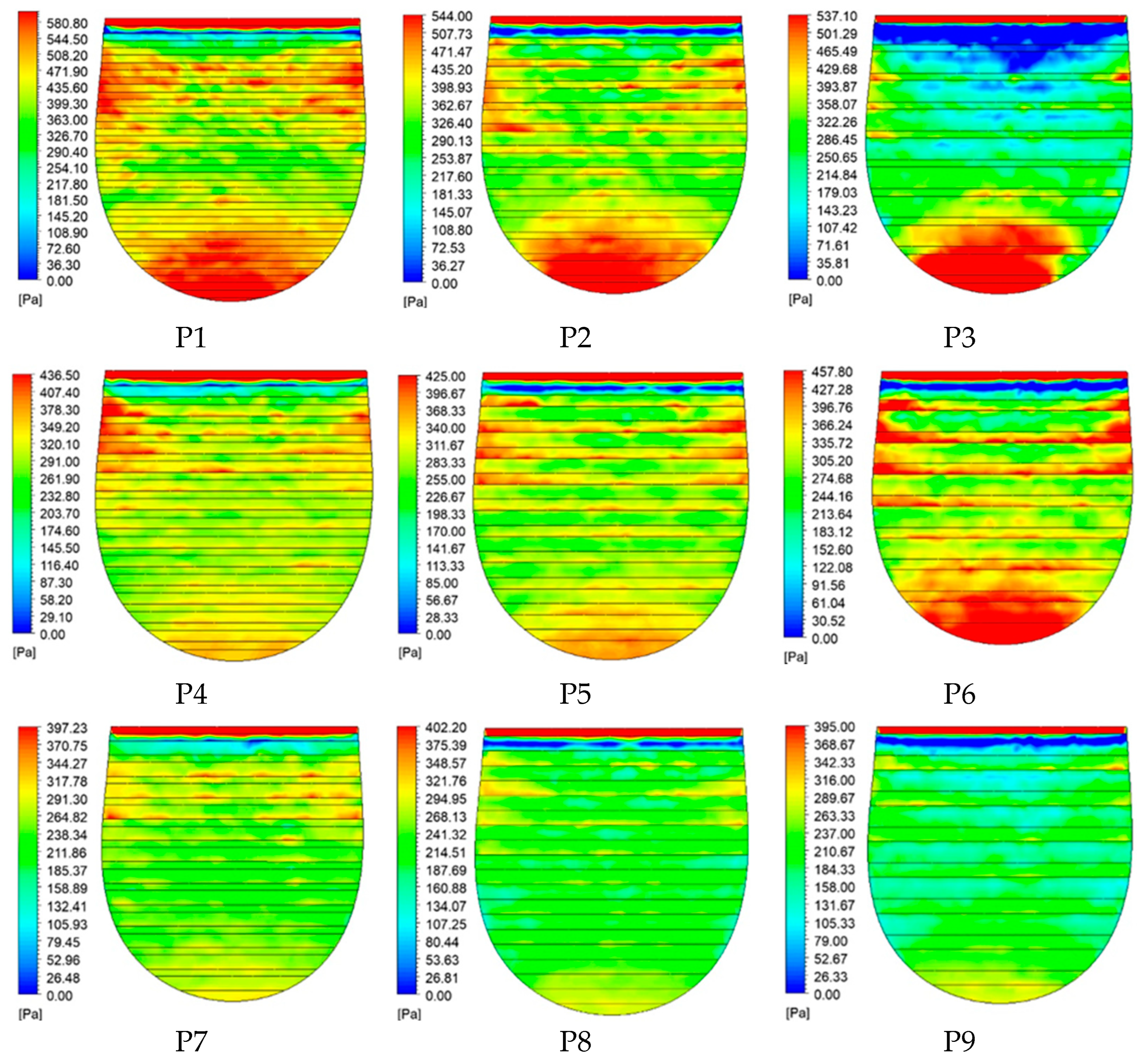
The peak gauge fluid pressures induced on the outsoles of the footwear varied from 395 Pa to 580.80 Pa. Figure 7 presents the induced fluid pressure contours on the outsole models. Outsole P1 exhibited the highest induced pressure (i.e., 580.80 Pa) compared to other outsoles. The pressure was approx. 1.5 times higher than P9, which exhibited the lowest induced fluid pressure (i.e., 395 Pa). Outsoles P1, P2, P3 showed similar fluid pressure contours having values 580.80 Pa, 544 Pa, and 537.10 Pa, respectively. Outsoles P4, P5, and P6 showed a pressure reduction of 24% to 30% as P4 experienced 436.50 Pa, P5 experienced 425 Pa, and P6 experienced 457.80 Pa. Furthermore, P7, P8, P9 exhibited the lowest fluid pressures ranging from 395 Pa to 402.20 Pa. P7 showed a fluid pressure of 397.23 Pa, P8 showed 402.20 Pa, and P9 showed 395 Pa with distributed and limited localized zones.
Figure 8 presents the average mass flow rates across the outsoles during the wet slip testing simulations. The flow rates across the footwear outsoles ranged between 0.051 kg/s and 0.089 kg/s. Out of all the outsoles, P9 exhibited the maximum mass flow rate of 0.089 kg/s throughout the topography. On the contrary, P1 reported the lowest mass flow rate of 0.051 kg/s, across its treads, during the wet slip simulation. Outsole P2 reported a similar flow rate (i.e., 0.052 kg/s) as compared to P1, which showed difficulty in streamlining the water flow through their treads. Besides P1, P2, P3, the remaining outsoles exhibited increased mass flow rates in the ranges of 0.070 kg/s to 0.089 kg/s. The highest mass flow rates were for P7 with 0.087 kg/s, P8 with 0.086 kg/s, and P9 with 0.089 kg/s.

3.3. Effect of Tread Parameters on Outcome Variables

3.3.1. Effect of Tread Width on ACOF, Fluid Pressure, and Mass Flow Rate

The effect of varying tread widths (i.e., width = 2 mm, 4 mm, 6 mm) on the outsole traction was quantified by estimating the correlations of changing widths with the ACOF (Figure 9). In a dry condition, a tread width was reported to be strongly and inversely correlating with the ACOF (R2 = 0.84) (Figure 9a). Specifically, outsoles P1, P4, and P7, which had smaller width, exhibited higher ACOF compared to other outsoles. The outsoles P2, P5, and P8, which had tread width of 4 mm, showed moderate ACOF values. The remaining outsoles, which had wider treads, showed a lower ACOF as compared to other outsoles. In wet slip testing, tread width as a varying parameter was found to weakly correlate (R2 = 0.01) with the ACOF (Figure 9b). Irrespective of the tread width, outsoles showed both lower and higher ACOF.
In wet slipping simulations, the effect of varying tread width on fluid pressure and mass flow rate were assessed by estimating the quality of correlations between them (Figure 10). Tread width and fluid pressure were found to be weakly correlated (R2 = 0.13) (Figure 10a). Fluid pressure across each width ranged from 395 Pa to 580.80 Pa and no localized zones were formed. Similarly, tread width and mass flow rate were reported to be weakly correlated (R2 = 0.01) (Figure 10b). Mass flow rates were distributed across the outsoles and no significant trends were observed.

3.3.2. Effect of Tread Gaps on ACOF, Fluid Pressure, and Mass Flow Rate

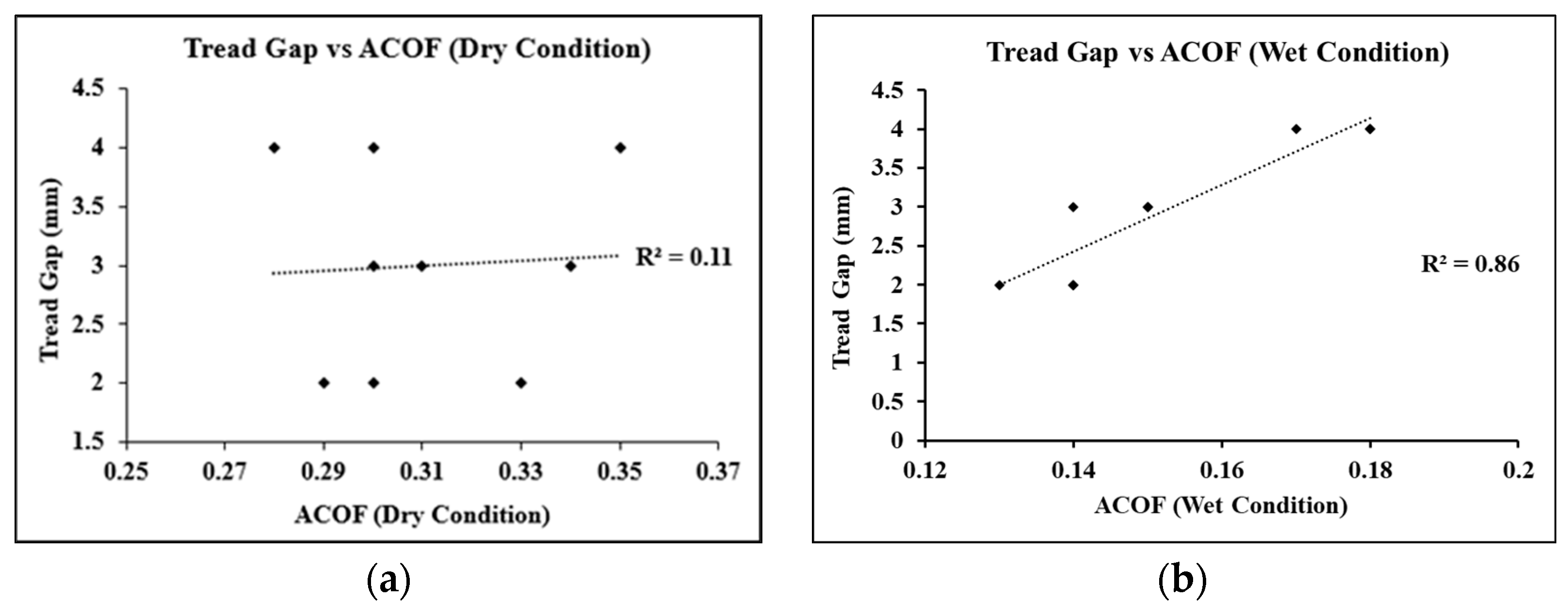
The effect of varying tread gaps (i.e., gap = 2 mm, 3 mm, 4 mm) on the traction was quantified by estimating the correlations of tread gaps with the ACOF (Figure 11). In dry conditions, tread gap weakly correlated with the ACOF (R2 = 0.11) (Figure 11a). The ACOF varied widely and no trend was observed when tread gaps and ACOF were compared. In wet slip testing, tread gap as a varying parameter was found to strongly and positively correlate (R2 = 0.86) with the ACOF (Figure 11b). In this case, outsoles which had larger tread gaps (i.e., P7, P8, P9) exhibited increased ACOF as compared to other outsoles (i.e., P1, P2, P3) in water as a contaminant condition.
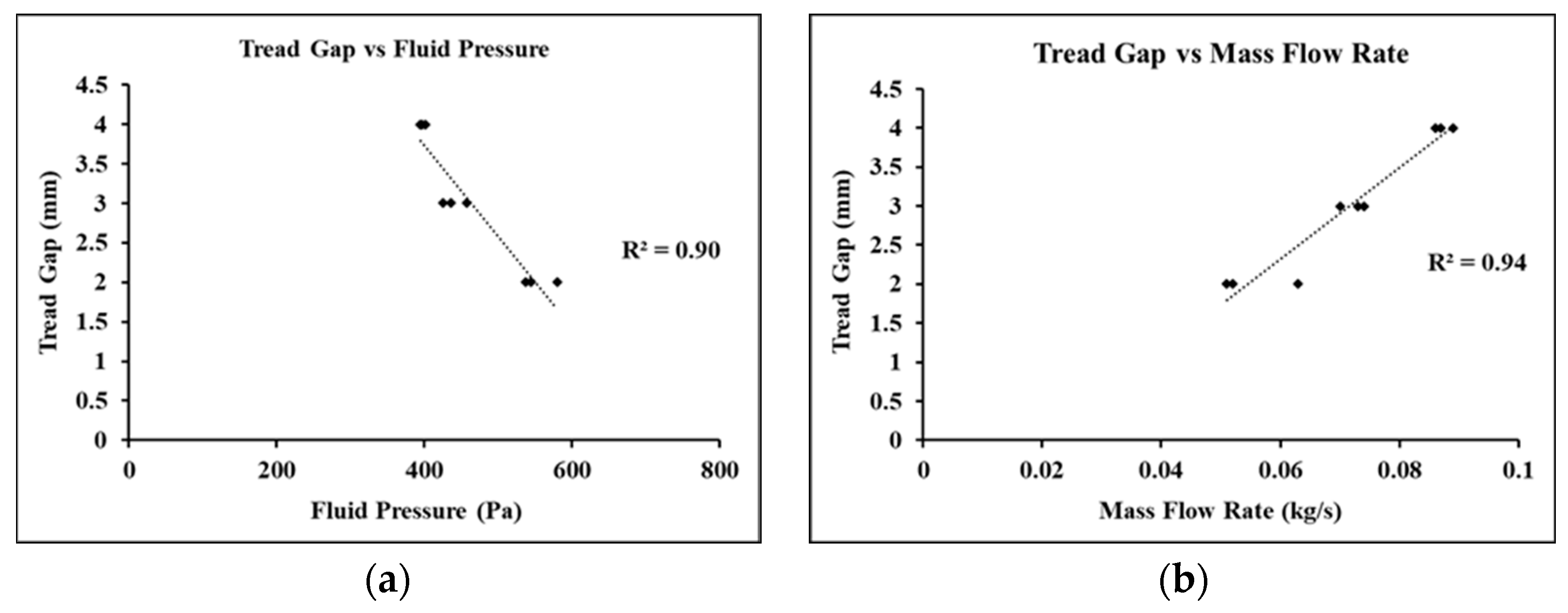
In wet slipping simulations, the effect of varying tread gap on fluid pressure and mass flow rate were quantified by estimating the quality of correlations between them (Figure 12). Tread gap and fluid pressure were reported to be strongly and negatively correlated (R2 = 0.90) (Figure 12a). Fluid pressures across a gap of 2 mm were in the range 537.10 Pa to 580.80 Pa, a 3 mm gap ranged from 425 Pa to 457.80 Pa, and a 4 mm gap varied from 395 Pa to 402 Pa. Similarly, tread gap and mass flow rate were reported to be strongly and positively correlated (R2 = 0.94) (Figure 12b). Flow rates across a gap of 2 mm were in the range of 0.051 kg/s to 0.063 kg/s, a 3 mm gap ranged from 0.070 kg/s to 0.074 kg/s, and a 4 mm gap varied from 0.087 kg/s to 0.089 kg/s.

4. Discussion

This current work demonstrates the effect of tread parameters on the traction performance of footwear having horizontally oriented outsole treads. Based on the varying tread widths (i.e., 2 mm, 4 mm and 6 mm) and tread gaps (i.e., 2 mm, 3 mm and 4 mm), nine outsole designs were developed and tested for induced fluid pressure and mass flow rates using a novel computational framework, and their traction performance was estimated using mechanical slip testing. The findings from the study indicated that the tread parameters have significant influence on the footwear traction on both dry and wet flooring.
In the case of dry slip testing, a majority of the outsoles, except two, were observed to cross the threshold ACOF of 0.3. Both exceptions had the same highest tread width (i.e., 6 mm), and varying tread gaps. Treads with the highest width showed less variations in the treads, which could have led to less deformations during the slipping motion. Compared to these outsoles, patterns which had similar and the lowest tread widths (i.e., 2 mm and 4 mm), reported the high ACOF outcomes. This may be in contradiction with the fact that larger contact areas lead to higher friction outcomes. Possible reasons for the lowest width treads showing high friction outcomes could be the increased bending ability of the treads (due to reduced structural strength), which led to the increased hysteresis friction. Unlike dry slip testing, the ACOF in wet slip testing exhibited a nearly generalizable trend with minimal differences across all the outsoles. This could be due to the dominance of formation of fluid films which resulted in such generalized friction outcomes. Minor differences were observed, which were due to the tread gaps implemented on the outsoles. Overall, the study results such as the friction outcomes of the outsoles in dry and wet conditions on the laminate flooring were similar to the previous study by Iraqi et al. [5], which showed the ACOF ranging from approximately 0.20 to 0.38.
The induced fluid pressure was characterized to estimate a tread pattern’s ability to allow fluid flow on wet flooring. All the outsoles behaved as a barrier to the flowing fluid due to their horizontal geometry (i.e., orthogonal to the direction of slip). Specifically, in a few outsoles, high fluid pressure accumulation zones could be identified at the entry and exit locations. Additionally, moderate to low mass flow rates were observed for these outsoles, which may have led to the formation of thick fluid films over the treads, their entrapment inside the tread gaps, and an overall increase in the induced fluid pressures. Across the outsoles, the ones with low gaps were found to allow minimal fluid flow and exhibit low ACOFs. Comparatively, the outsoles with large tread gaps were found to generate better fluid flow and higher ACOF. Overall, high correlations were observed between the tread gap and the ACOF during slipping on wet flooring. Additionally, highly negative and positive correlations were observed between the tread gap and induced fluid pressure and mass flow rate, respectively.
Some limitations of this current work should be acknowledged. Although the developed computational framework was found to be converged and accurate, the computation time to solve the problem was significantly high (i.e., 6 h). This could further be solved by using advanced meshing and modelling techniques. Another limitation is the consideration of single outsole material (i.e., polyurethane). Although this material is widely used as outsole materials, other materials were not tested in this study. Future studies considering a range of materials and outsole designs could further help in determining the accuracy of this framework.

5. Conclusions

In conclusion, parametrical variations in the horizontal tread patterns were found to affect the traction performance of the footwear outsoles. The fluid pressure and mass flow rates were assessed using a turbulent k-epsilon model. The outsoles which had wide treads (i.e., more than 4 mm) with small gaps may increase the overall slipping risk and vice versa, on dry flooring. However, varying outsole width is not expected to affect the footwear traction much in the case of wet flooring. The outsoles which had large tread gaps (i.e., 4 mm) are anticipated to generate low fluid pressures, high fluid flow, and high traction during slipping on wet flooring. The results from this study are anticipated to not only advance our knowledge on the science of footwear, but also provide important guidelines for the footwear industry to optimize tread geometries to reduce the risk of slips and falls.

Author Contributions

S.G.: methodology; validation; investigation; formal analysis; writing—original draft; writing—review and editing. S.C.: validation; investigation; formal analysis; data curation. A.M.: validation; investigation; data curation. G.S.: validation; investigation; data curation. A.C.: conceptualization; methodology; formal analysis; supervision; writing—review and editing. All authors have read and agreed to the published version of the manuscript.

Funding

We would like to acknowledge the funding support received from SERB-DST and IRD, IIT Delhi.

Data Availability Statement

The datasets generated during and/or analyzed during this current study are not publicly available due to large datasets but are available from the corresponding author on reasonable request.

Conflicts of Interest

The authors declare no conflict of interest.

References

  1. Health and Safety Executive. Kind of Accident Statistics in Great Britain; Health and Safety Executive: Bootle, UK, 2021. [Google Scholar]
  2. Libery Mutual. 2017 Liberty Mutual Workplace Safety Index; Libery Mutual: Boston, MA, USA, 2017; Available online: https://www.mhi.org/downloads/industrygroups/ease/resources/2017-WSI.pdf (accessed on 20 September 2022).
  3. Bell, J.L.; Collins, J.W.; Wolf, L.; Grönqvist, R.; Chiou, S.; Chang, W.-R.; Sorock, G.S.; Courtney, T.; Lombardi, D.A.; Evanoff, B.A. Evaluation of a comprehensive slip, trip and fall prevention programme for hospital employees. Ergonomics 2008, 51, 1906–1925. [Google Scholar] [CrossRef] [PubMed]
  4. Beschorner, K.E.; Li, Y.; Yamaguchi, T.; Ells, W.; Bowman, R. The Future of Footwear Friction. In Proceedings of the 21st Congress of the International Ergonomics Association (IEA 2021) Volume V: Methods & Approaches 21; Springer: Cham, Switzerland, 2021; pp. 841–855. [Google Scholar] [CrossRef]
  5. Iraqi, A.; Vidic, N.S.; Redfern, M.S.; Beschorner, K.E. Prediction of coefficient of friction based on footwear outsole features. Appl. Ergon. 2019, 82, 102963. [Google Scholar] [CrossRef] [PubMed]
  6. Beschorner, K.E.; Siegel, J.L.; Hemler, S.L.; Sundaram, V.H.; Chanda, A.; Iraqi, A.; Haight, J.M.; Redfern, M.S. An observational ergonomic tool for assessing the worn condition of slip-resistant shoes. Appl. Ergon. 2020, 88, 103140. [Google Scholar] [CrossRef] [PubMed]
  7. Beschorner, K.E.; Redfern, M.S.; Porter, W.L.; Debski, R.E. Effects of slip testing parameters on measured coefficient of friction. Appl. Ergon. 2007, 38, 773–780. [Google Scholar] [CrossRef]
  8. Chatterjee, S.; Gupta, S.; Chanda, A. Barefoot Slip Risk in Indian Bathrooms: A Pilot Study. Tribol. Trans. 2022, 65, 977–990. [Google Scholar] [CrossRef]
  9. Gupta, S.; Chatterjee, S.; Malviya, A.; Chanda, A. Frictional Assessment of Low-Cost Shoes in Worn Conditions Across Workplaces. J. Bio- Tribo-Corrosion 2023, 9, 23. [Google Scholar] [CrossRef]
  10. Gupta, S.; Chatterjee, S.; Chanda, A. Effect of footwear material wear on slips and falls. Mater. Today Proc. 2022, 62, 3508–3515. [Google Scholar] [CrossRef]
  11. Chanda, A.; Jones, T.G.; Beschorner, K.E. Generalizability of Footwear Traction Performance across Flooring and Contaminant Conditions. IISE Trans. Occup. Ergon. Hum. Factors 2018, 6, 98–108. [Google Scholar] [CrossRef]
  12. Chatterjee, S.; Gupta, S.; Chanda, A. Barefoot slip risk assessment of Indian manufactured ceramic flooring tiles. Mater. Today Proc. 2022, 62, 3699–3706. [Google Scholar] [CrossRef]
  13. Chang, W.-R.; Grönqvist, R.; Leclercq, S.; Myung, R.; Makkonen, L.; Strandberg, L.; Brungraber, R.J.; Mattke, U.; Thorpe, S.C. The role of friction in the measurement of slipperiness, Part 1: Friction mechanisms and definition of test conditions. Ergonomics 2001, 44, 1217–1232. [Google Scholar] [CrossRef]
  14. Chang, W.-R.; Grönqvist, R.; Leclercq, S.; Brungraber, R.J.; Mattke, U.; Strandberg, L.; Thorpe, S.C.; Myung, R.; Makkonen, L.; Courtney, T. The role of friction in the measurement of slipperiness, Part 2: Survey of friction measurement devices. Ergonomics 2001, 44, 1233–1261. [Google Scholar] [CrossRef] [PubMed]
  15. Chang, W.-R.; Lesch, M.F.; Chang, C.-C. The effect of contact area on friction measured with the portable inclinable articulated strut slip tester (PIAST). Ergonomics 2008, 51, 1984–1997. [Google Scholar] [CrossRef] [PubMed]
  16. Bergström, A.; Åström, H.; Magnusson, R. Friction Measurement on Cycleways Using a Portable Friction Tester. J. Cold Reg. Eng. 2003, 17, 37–57. [Google Scholar] [CrossRef]
  17. Andres, R.O.; Chaffin, N.B. Ergonomic analysis of slip-resistance measurement devices. Ergonomics 1985, 28, 1065–1079. [Google Scholar] [CrossRef]
  18. Grönqvist, R.; Roine, J.; Järvinen, E.; Korhonen, E. An apparatus and a method for determining the slip resistance of shoes and floors by simulation of human foot motions. Ergonomics 1989, 32, 979–995. [Google Scholar] [CrossRef]
  19. Blanchette, M.G.; Powers, C.M. The influence of footwear tread groove parameters on available friction. Appl. Ergon. 2015, 50, 237–241. [Google Scholar] [CrossRef]
  20. Beschorner, K.E.; Iraqi, A.; Redfern, M.S.; Cham, R.; Li, Y. Predicting slips based on the STM 603 whole-footwear tribometer under different coefficient of friction testing conditions. Ergonomics 2019, 62, 668–681. [Google Scholar] [CrossRef]
  21. Strobel, C.M.; Menezes, P.L.; Lovell, M.R.; Beschorner, K.E. Analysis of the Contribution of Adhesion and Hysteresis to Shoe–Floor Lubricated Friction in the Boundary Lubrication Regime. Tribol. Lett. 2012, 47, 341–347. [Google Scholar] [CrossRef]
  22. Jones, T.; Iraqi, A.; Beschorner, K. Performance testing of work shoes labeled as slip resistant. Appl. Ergon. 2018, 68, 304–312. [Google Scholar] [CrossRef]
  23. Tsai, Y.-J.; Powers, C.M. The Influence of Footwear Sole Hardness on Slip Initiation in Young Adults. J. Forensic Sci. 2008, 53, 884–888. [Google Scholar] [CrossRef]
  24. Yamaguchi, T.; Katsurashima, Y.; Hokkirigawa, K. Effect of rubber block height and orientation on the coefficients of friction against smooth steel surface lubricated with glycerol solution. Tribol. Int. 2017, 110, 96–102. [Google Scholar] [CrossRef]
  25. Li, K.W.; Chen, C.J. The effect of shoe soling tread groove width on the coefficient of friction with different sole materials, floors, and contaminants. Appl. Ergon. 2004, 35, 499–507. [Google Scholar] [CrossRef] [PubMed]
  26. Beschorner, K.E.; Albert, D.L.; Chambers, A.J.; Redfern, M.S. Fluid pressures at the shoe–floor–contaminant interface during slips: Effects of tread & implications on slip severity. J. Biomech. 2014, 47, 458–463. [Google Scholar] [CrossRef]
  27. Hemler, S.L.; Charbonneau, D.N.; Beschorner, K.E. Predicting hydrodynamic conditions under worn shoes using the tapered-wedge solution of Reynolds equation. Tribol. Int. 2020, 145, 106161. [Google Scholar] [CrossRef]
  28. Meehan, E.E.; Vidic, N.; Beschorner, K.E. In contrast to slip-resistant shoes, fluid drainage capacity explains friction performance across shoes that are not slip-resistant. Appl. Ergon. 2021, 100, 103663. [Google Scholar] [CrossRef] [PubMed]
  29. Hemler, S.L.; Charbonneau, D.N.; Beschorner, K.E. Effects of Shoe Wear on Slipping—Implications for Shoe Replacement Threshold. Proc. Hum. Factors Ergon. Soc. Annu. Meet. 2017, 61, 1424–1428. [Google Scholar] [CrossRef]
  30. Moghaddam, S.R.M.; Acharya, A.; Redfern, M.S.; Beschorner, K.E. Predictive multiscale computational model of shoe-floor coefficient of friction. J. Biomech. 2018, 66, 145–152. [Google Scholar] [CrossRef]
  31. Moghaddam, S.R.M.; Hemler, S.L.; Redfern, M.S.; Jacobs, T.D.; Beschorner, K.E. Computational model of shoe wear progression: Comparison with experimental results. Wear 2019, 422–423, 235–241. [Google Scholar] [CrossRef]
  32. Beschorner, K.E.; Meehan, E.E.; Iraqi, A.; Hemler, S.L. Designing shoe tread for friction performance: A hierarchical approach. Footwear Sci. 2021, 13, S97–S99. [Google Scholar] [CrossRef]
  33. Gupta, S.; Malviya, A.; Chatterjee, S.; Chanda, A. Development of a Portable Device for Surface Traction Characterization at the Shoe–Floor Interface. Surfaces 2022, 5, 504–520. [Google Scholar] [CrossRef]
  34. ASTM F2913-19; Standard Test Method for Measuring the Coefficient of Friction for Evaluation of Slip Performance of Footwear and Test Surfaces/Flooring Using a Whole Shoe Tester. ASTM International: West Conshohocken, PA, USA, 2019.
  35. Gupta, S.; Chatterjee, S.; Malviya, A.; Chanda, A. Traction Performance of Common Formal Footwear on Slippery Surfaces. Surfaces 2022, 5, 489–503. [Google Scholar] [CrossRef]
  36. Gupta, S.; Sidhu, S.S.; Chatterjee, S.; Malviya, A.; Singh, G.; Chanda, A. Effect of Floor Coatings on Slip-Resistance of Safety Shoes. Coatings 2022, 12, 1455. [Google Scholar] [CrossRef]
  37. Aschan, C.; Hirvonen, M.; Mannelin, T.; Rajamäki, E. Development and validation of a novel portable slip simulator. Appl. Ergon. 2005, 36, 585–593. [Google Scholar] [CrossRef] [PubMed]
  38. Chanda, A.; Chatterjee, S.; Gupta, V. Soft composite based hyperelastic model for anisotropic tissue characterization. J. Compos. Mater. 2020, 54, 4525–4534. [Google Scholar] [CrossRef]
  39. Rodrigues, P.V.; Ramoa, B.; Machado, A.V.; Cardiff, P.; Nóbrega, J.M. Assessing the Compressive and Impact Behavior of Plastic Safety Toe Caps through Computational Modelling. Polymers 2021, 13, 4332. [Google Scholar] [CrossRef] [PubMed]
  40. Singh, G.; Gupta, S.; Chanda, A. Biomechanical modelling of diabetic foot ulcers: A computational study. J. Biomech. 2021, 127, 110699. [Google Scholar] [CrossRef] [PubMed]
  41. Gupta, S.; Singh, G.; Chanda, A. Prediction of diabetic foot ulcer progression: A computational study. Biomed. Phys. Eng. Express 2021, 7, 065020. [Google Scholar] [CrossRef]
  42. Gupta, S.; Gupta, V.; Chanda, A. Biomechanical modeling of novel high expansion auxetic skin grafts. Int. J. Numer. Methods Biomed. Eng. 2022, 38, e3586. [Google Scholar] [CrossRef]
  43. Adams, T.; Grant, C.; Watson, H. A Simple Algorithm to Relate Measured Surface Roughness to Equivalent Sand-grain Roughness. Int. J. Mech. Eng. Mechatron. 2012, 1, 66–71. [Google Scholar] [CrossRef] [Green Version]
Figure 1. Dimensions of the original footwear tread design.
Computation 11 00023 g001
Figure 2. The developed parametrically modified footwear outsole designs.
Computation 11 00023 g002aComputation 11 00023 g002b
Figure 3. Whole-shoe portable slip testing device [33].
Computation 11 00023 g003
Figure 4. The generated meshes for: (a) surface and (b) outsole.
Computation 11 00023 g004
Figure 5. Computational domain and the boundary conditions used to simulate the wet slipping condition.
Computation 11 00023 g005
Figure 6. Traction performance of the outsoles tested using the mechanical slip tester.
Computation 11 00023 g006
Figure 7. Induced fluid pressures over the outsoles simulated in the presence of water as contaminant.
Computation 11 00023 g007
Figure 8. Mass flow rates through the outsole treads due to slipping simulations in the presence of water as a contaminant.
Computation 11 00023 g008
Figure 9. Effect of tread width on ACOF: (a) in dry condition and (b) in wet condition.
Computation 11 00023 g009
Figure 10. Effect of tread width: (a) induced fluid pressure and (b) mass flow rate.
Computation 11 00023 g010
Figure 11. Effect of tread gap on ACOF: (a) in dry condition and (b) in wet condition.
Computation 11 00023 g011
Figure 12. Effect of tread gap on: (a) induced fluid pressure and (b) mass flow rate.
Computation 11 00023 g012
Table 1. Parametrical modifications in the outsole’s design.
Outsole NomenclatureWidth (mm)Gap (mm)
P122
P242
P362
P423
P543
P663
P724
P844
P964
Disclaimer/Publisher’s Note: The statements, opinions and data contained in all publications are solely those of the individual author(s) and contributor(s) and not of MDPI and/or the editor(s). MDPI and/or the editor(s) disclaim responsibility for any injury to people or property resulting from any ideas, methods, instructions or products referred to in the content.