1. Introduction
The main task in designing in the aerospace industry is the optimization of a unit and mechanisms. However, the geometry, constituent elements and type of load in most cases do not allow one to use accurate calculation methods. In this case, it is necessary to use time-consuming tests [
1], in which the changing of geometrical characteristics leads to changes in physical and mechanical properties and new tests being required. The other way is to simplify the calculation model or to obtain the stress-strain state of the body by approximate methods [
2]. The last two options do not provide certainty in the calculations results and are compensated by additional safety factors. Therefore, it is important to have a method that will allow one to obtain the stress-strain state of the body with a higher accuracy, taking into account the geometry and existing stress concentrators.
Approximate, exact and experimental methods are often combined with one another to increase the accuracy of the calculation. Thus, analytical, numerical and experimental research was carried out for a multilayer composite with a perpendicularly located cylindrical hole [
3]. In an analytical study, the point stress criterion is developed. The finite element method is used in a numerical study. In [
4], the analysis of the stress state for a plate with a cylindrical hole was carried out. The solution of the problem is based on metaheuristic optimization algorithms around stress concentrators. In paper [
5], a plate with a cylindrical hole is also considered, but here the semi-analytical polynomial method is used. In this case, nonlinear partial differential equations were transformed into a system of nonlinear algebraic equations, and the Newton-Raphson method was applied. In [
6], the complex potential method was used to study the bending of finite isotropic rectangular plates with a circular cutout. Combinations of described methods [
3,
4,
5,
6] effectively solve the problem with a perpendicularly located stress concentrator, but their application is not possible for longitudinal inhomogeneities and for cases of periodic loading.
In work [
7], in order to calculate the reaction of a layered composite to an impact load, an analytical-experimental approach is proposed. In this case, analytical modeling is based on the decomposition into a power series of the component of the displacement vector in each layer for the transverse coordinate. In the experimental part, the maximum deflections of composite samples during the impact of the indenter are considered. In work [
8], an analysis of the strength-laminated windows of an airplane cabin against a bird strike was carried out. The calculation method is based on embedding the original non-canonical shell into an auxiliary canonical form in a plane with boundary conditions. As a result, a simple analytical problem in the form of a trigonometric series is formed. An experimental model was developed to simulate the process of a bird hitting a hard target [
9]. In work [
10], the first-order theories for the analytical model of multilayer glazing are improved; they take into account the transverse shear deformations, thickness reduction and normal inertia of rotation of the elements of each layer. The mathematical model of the pressure pulse was experimentally investigated. The cited works [
7,
8,
9,
10] effectively determine the strength of layered composites but do not allow one to take longitudinal inhomogeneities into account.
To take into account longitudinal inhomogeneities, analytical or analytical-numerical methods use the Fourier series decomposition. Thus, in [
11], steady-state problems of wave diffraction in a plate and a layer are solved on the basis of Fourier series. The paper [
12] defines the diffraction of waves in space, half-space and an infinite layer that have a cavity or inclusion. The stress state for a layer with a cylindrical cavity or inclusion is considered in [
13]. In [
14], a layer with a cylindrical cavity or inclusion is considered, and the image method is used to solve the two-dimensional boundary value problem of the diffraction of symmetric normal longitudinal shear waves. These approaches [
11,
12,
13,
14] make it possible to obtain a highly accurate stress distribution or wave diffraction result for problems in a flat setting. However, these methods cannot be applied to a spatial problem and a problem with many boundary surfaces.
For a high-precision determination of the stress state of spatial models and for models with more than three boundary surfaces, the analytical-numerical generalized Fourier method [
15] is most powerful. The paper [
16] presents the substantiation of this method for the basic solutions of the Lamé equation for a half-space and a cylinder, written in the Cartesian and cylindrical coordinate systems, respectively. This makes it possible to solve the problem with flat and cylindrical surfaces.
Using the generalized Fourier method, a number of problems for a cylinder with cylindrical cavities or inclusions were solved. Thus, in [
17], the problem was solved for a cylinder with four cylindrical cavities. The problem for a cylinder with N cylindrical cavities is considered in work [
18], for a cylinder with cylindrical cavities forming a hexagonal structure in work [
19], and for a cylinder with 16 cylindrical inclusions in work [
20]. These papers [
17,
18,
19,
20] only apply the addition theorems of the generalized Fourier method for several cylindrical coordinate systems. This effectively solves problems for combinations of cylindrical surfaces but does not provide the ability to solve problems for a layer.
The use of the addition formulas of the generalized Fourier method for solutions of the Lamé equation between Cartesian and cylindrical coordinate systems is taken into account in other works. Thus, in [
21], elasticity theory problems for a half-space with cylindrical cavities in displacements were solved. The mixed type is solved in [
22]. In [
23], the lower limit is taken into account, and the problem is solved for a layer with one cylindrical cavity in displacements. A problem with given stresses on the boundaries is solved in [
24] and one of mixed type is solved in [
25]. A layer conjugated with a half-space that has a cylindrical cavity is considered in [
26]. A layer with one continuous inclusion is solved in paper [
27] and one with two continuous inclusions is solved in paper [
28]. In works [
21,
22,
23,
24,
25,
26,
27,
28], the double Fourier integral is applied to boundary conditions, which limits the range of use to rapidly decreasing functions only. This makes it impossible to take into account periodic displacements or stresses (for example, from located equipment or technological fastenings) when the loads are applied periodically through some constant interval of distance to infinity.
Therefore, the problem for a layer with a cylindrical cavity can be solved with high accuracy using the analytical-numerical generalized Fourier method. However, unlike existing works, it is necessary to apply additional methods to account for periodic loads and it is necessary to combine these methods.
Despite the large number of publications on the subject of calculating the layer with stress concentrators, there are in practice still many unresolved problems that occur during the design. The absence of a method for calculating such problems allows one to assert the relevance of conducting a study dedicated to the spatial calculation of a layer with a cylindrical cavity and specified periodic displacements. It should be noted that, in this paper, only linear elastic materials are considered.
2. Problem Statement, Materials and Methods of Analyzing the Stress State of the Layer
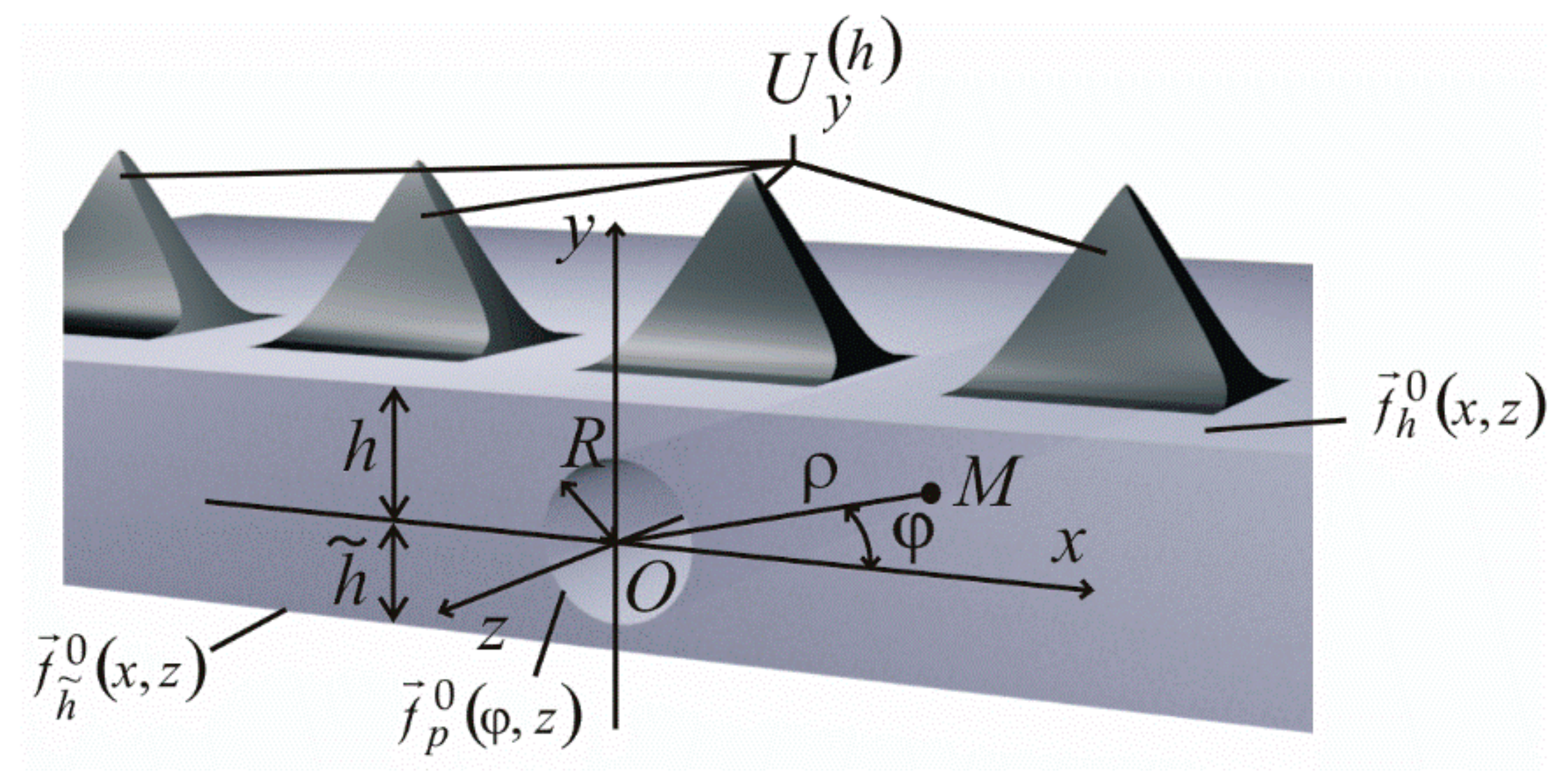
The object of research is the stress-strain state of a layer with a longitudinal circular infinite cylindrical cavity (
Figure 1). The distance from the center of the cavity with a radius
R to the upper boundary of the layer is
y =
h, and the distance to the lower boundary is
. The distances
h and
can have any value greater than
R (
h >
R <
). A static load acts on the layer in the form of displacement (the second main task of the elasticity theory). In the theoretical formulation, the displacements at the upper boundary of the layer are taken into account in the form of periodic functions
along the
x-axis. The material of the layer is elastic, isotropic and homogeneous with linear elastic characteristics.
The cavity does not intersect with the boundaries of the layer and is considered in the cylindrical coordinate system (
ρ,
φ,
z). The layer is considered in the Cartesian coordinate system (
x,
y,
z), which is equally oriented and connected with the coordinate system of the cylinder. The distance from the cavity center to the upper boundary of the layer is
y =
h, and the distance to the lower boundary is
. One needs to find a solution to the Lamé equation. Displacements are set on the layer boundaries
, there
—known functions. Among these functions,
(
Figure 1),
—where there are periodic functions along the
x axis and rapidly decreasing to zero along the
z axis. Other functions are assumed to rapidly decrease to zero at large distances from the origin along the z coordinate for the cylinder and along the x and z coordinates for the layer boundaries.
The basic solutions of the Lamé equation are chosen in the form [
15]
where
ν—Poisson’s ratio;
,
—modified Bessel functions;
,
k = 1, 2, 3—internal and external solutions of the Lamé equation for the cylinder, respectively;
—solutions of the Lamé equation for the layer.
Theorems for the addition of basic solutions in different coordinate systems have the form [
15]:
–transition from the solutions
of the cylindrical coordinate system to the layer solutions
(at
y > 0) and
(at
y < 0)
where
;
;
;
and
—coordinates for the shifted coordinate system (in our case, equal to zero);
–transition from solutions
and
of the layer to solutions
of the cylinder
where
;
;
; , , —orths of the cylindrical coordinate system.
3. Problem Solving and Stress State Research Results
3.1. Creation and Solving a System of Equations
To take into account the specified periodic displacements, an auxiliary problem was solved for a layer without a cavity in the form
where
and
—the basic solutions, which are given by formulas (2), and where the unknown functions
,
must be found from the boundary conditions, which are represented by periodic functions.
To take into account the boundary conditions at the lower boundary of the layer, Equation (5), at
y =
, is set to zero. At the upper boundary of the layer, the vector (5), at
y =
h, is equal to the given
, represented by the integral and the Fourier series
where
—function period; .
After equating the vector coefficients at
, one obtains
Equation (7) is projected on the coordinate axis (equalized projections with base vectors
) and expressed as
and
where
,
k = 1, 2, 3—basis vectors of the Cartesian coordinate system; j = 1, 2, 3;
—algebraic complement of the system of equations; and D—the determinant of the system of equations.
After determining the unknowns
and
by using transition formulas (4), expression (7) is rewritten in the cylindrical coordinate system through basic solutions
and found displacements at the place where the surface of the cavity is geometrically located. When releasing from the integral over
λ and
, one obtains
where
—presented in formula (6).
After finding the imprint of the periodic function at the location of the cavity (8), the main problem of the generalized Fourier method is solved, the solution of which is given in the form
where
—presented in formula (5);
,
and
—the basic solutions given by formula (2), and the unknown functions
,
and
must be determined from the boundary conditions (1), taking into account the additional function (8) with the opposite sign on the cavity surface.
Finding the unknowns
,
and
was carried out as in [
23].
That is, in order to fulfill the boundary conditions on the lower boundary of the layer y =
, the vectors
in (9) are rewritten in the Cartesian coordinate system using the transition formulas (3) through the basic solutions
. The resulting vectors are equated, at y =
, given by
, represented by the double Fourier integral
At the upper boundary of the layer, the boundary conditions are taken into account in Equation (5), so Equation (9) equals zero at y = h. At the same time, the vectors in (9) are rewritten in the Cartesian coordinate system through the basic solutions using the transition Formulas (3).
The functions and expressed through are found from these equations.
To fulfill the boundary conditions on the cylinder ρ = R, the right part of (9) is rewritten in the cylindrical coordinate system through the base solutions using the transition formulas (4). The resulting vector is equated to , where is the given function (1), represented by an integral and Fourier series; is the density of the integral image (8).
The previously found functions and through are excluded from the resulting system of equations. As a result, a set of three systems of linear algebraic equations was obtained to determine the unknown .
The functions , found from the infinite system of equations, are substituted into the expressions for and . This determined all the unknown problems.
3.2. Numerical Analysis of the Stress State of the Layer
The layer properties (fine-grained concrete with quartz aggregate) were taken: modulus of elasticity E = 3.25·10
4 MPa and Poisson’s ratio
ν = 0.16 [
29]. The radius of the cylindrical cavity is R = 100 mm. The upper and lower boundaries of the layer (
Figure 1) are located relative to the center of the cavity at a distance of
h =
= 200 mm.
At the upper boundary of the layer along the
x-axis, a periodic function of displacements is set in the form
, on the lower boundary,
, and on the surface of the cavity displacement,
. The representation of the function
through the Fourier series along the
x-axis and the Fourier integral along the
z-axis has the form
The infinite system of equations was reduced to a finite one by the parameters m = 8 and n = 35. The accuracy of meeting the boundary conditions for the specified values of the geometric parameters is 10−3 for values equal to zero.
Stresses were determined along the
z axis (
Figure 2, line a), on the surface of the cylindrical cavity (
Figure 2, line b), on the isthmuses (
Figure 2, lines c and d), as well as on the upper boundary of the layer along the
x axis (
Figure 2, line k).
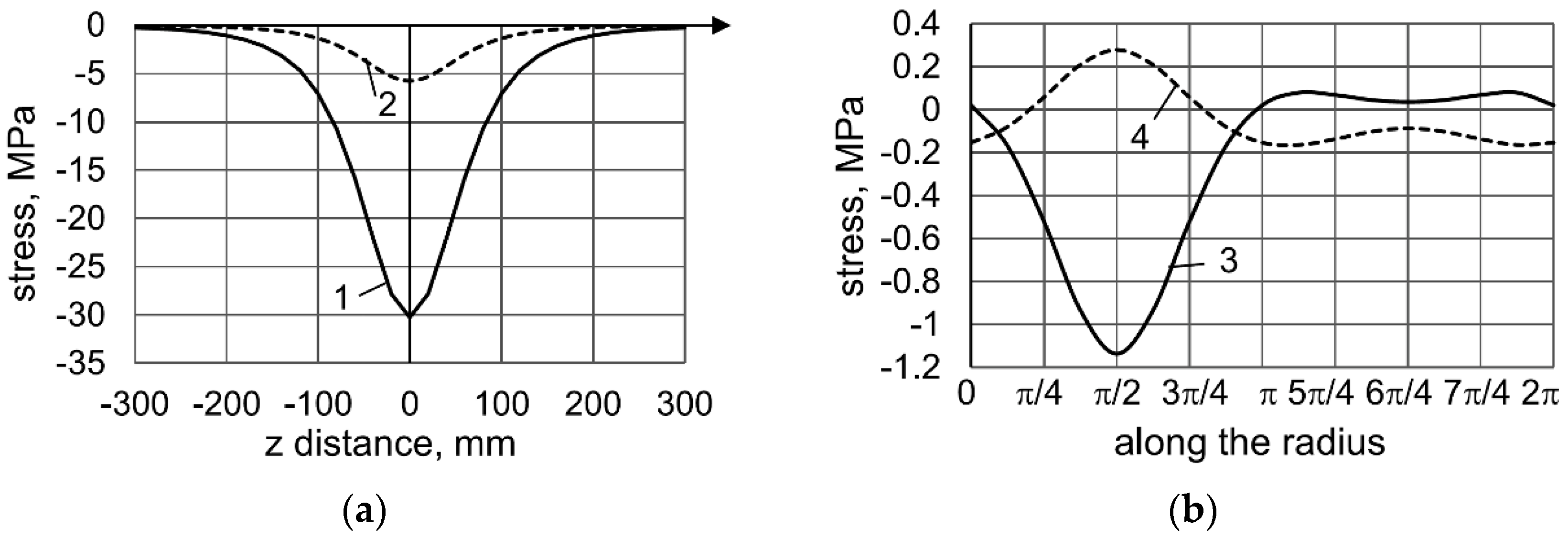
Figure 3a represents the stress state at the upper boundary of the layer along the
z axis, at
x = 0 (
Figure 2, line a).
Figure 3b represents the stress state on the surface of the cavity (
Figure 2, line b)
The stresses
(
Figure 3a, line 2) and
at the upper boundary of the layer along the
z axis coincide. The highest stress values are realized in the section
z = 0 and are equal to
= –30.2475 MPa,
= –5.7514 MPa.
On the surface of the cavity (
Figure 2, line b), the stresses decrease significantly (
Figure 3b). The highest stress values
, the maximum stress values
= –1.1359 MPa and
= 0.2793 MPa are observed in the upper part of the cavity (π/2).
The stresses at the isthmuses between the cavity and the layer boundaries at
z = 0 (
Figure 2, lines c and d) are represented in
Figure 4a,b.
The stresses along the isthmus from the upper boundary of the layer to the cavity (
Figure 4a) decrease quite quickly, so the influence of the cavity on the stresses is not strongly observed.
The stresses along the isthmus from the cavity to the lower boundary of the layer (
Figure 4b) also decrease. In addition, the stresses
and
change signs from “extensive” to “compressive”.
Figure 5 represents the stress distribution on the upper boundary of the layer along the
x axis at
z = 0 (
Figure 2, line k). The
and
stresses are similar, so the
stresses are not represented.
In the locations of the peak “load” of periodic displacement (0, ±10π, ±20π...), maximum negative values of stresses
arise (
Figure 5, line 1), which also have a periodic character. Between the “loads”, the stresses
become positive. The stresses
,
and
have small values (compared to
), whose maximum values also occur at the peak “load” locations.
4. Discussion
To take into account the periodic load, the solution of the additional problem (5) is applied for a layer without a cylindrical cavity, with the distribution of the load in a Fourier series (6) and the definition of displacements in place of the cavity impression (8). Next, the main problem is solved, where these displacements with the opposite sign are taken into account. The total result is the sum of two problems to be solved.
To obtain the stress state, the stress operator is applied for solutions (5) and (9). Using transition Formulas (3) and (4), it became possible to write solutions in one coordinate system and obtain a numerical result.
Unlike the existing papers [
17,
18,
19,
20,
21,
22,
23,
24,
25,
26,
27,
28], which also use the generalized Fourier method, an additional problem was applied in the presented work. This allows one to solve problems with boundary conditions in the form of functions directed to infinity.
The proposed high-precision solution method makes it possible to calculate the strength of the structure and its details, whose calculation scheme is a layer with a cylindrical cavity and boundary conditions in the form of periodic functions.
When applying the additional problem, one should take into account the limitation: such a technique is impossible in the direction of the z axis, where there is no expansion in a row along the radius of the cavity. However, taking into account the unchanged geometry of the body along this axis, the periodic load along the z axis can be taken into account without applying the proposed additional problem. In this case, the problem can be solved by the method of separation of variables in combination with the generalized Fourier method.
Further development of this direction is necessary for other types of boundary conditions (in stresses and mixed types).


