Article

Low-Complexity Synchronization Scheme with Low-Resolution ADCs

1
School of Automation and Electronic Information Engineering, Sichuan University of Science and Engineering, Zigong 643000, China
2
Artificial Intelligence Key Laboratory of Sichuan Province, Sichuan University of Science and Engineering, Zigong 643000, China
3
Advanced Avionics and Intelligent Information Laboratory of Shanghai Jiao Tong University, Shanghai 200240, China
*
Author to whom correspondence should be addressed.
Information 2018, 9(12), 313; https://doi.org/10.3390/info9120313
Submission received: 27 October 2018 / Revised: 23 November 2018 / Accepted: 6 December 2018 / Published: 7 December 2018

Abstract

:
An important function of next-generation (5G) and beyond mobile communication systems is aim to provide thousand-fold capacity growth and to support high-speed data transmission up to several megabits per second. However, the research community and industries have to face a dilemma of power consumption and hardware design to satisfy the increasing communication requirements. For the purpose of improving the system cost, power consumption, and implementation complexity, a novel scheme of symbol timing and frequency offset estimation with low-resolution analog-to-digital converters (ADCs) based on an orthogonal frequency division multiplexing ultra-wideband (OFDM-UWB) system is proposed in this paper. In our work, we first verified the principle that the autocorrelation of the pseudo-noise (PN) sequences was not affected by low-resolution quantization. With the help of this property, the timing synchronization could be strongly implemented against the influence of low-resolution quantization. Then, the transmitted signal structure and low-resolution quantization scheme under the synchronization scheme were designed. Finally, a frequency offset estimation model with one-bit timing synchronization was established. Theoretical analysis and simulation results corroborate that the performance of the proposed scheme not only approximates to that of the full-resolution synchronization scheme, but also has lower power consumption and computational complexity.

1. Introduction

As the bandwidth and antenna configurations of next-generation (5G) wireless systems continue increasing, various services and applications in 5G networks are deployed in a single system to meet high-speed access requirements in multi-user and multi-machine environments [1]. Ultra-wideband (UWB) communications attracted considerable interest, targeting applications in high-speed data transfer wireless communication systems [2]. A major benefit of such systems is the achievement of high data rates, with low power consumption and low system implementation cost [3]. UWB is recently seen as an indoor short-range high-speed wireless communication [4] with a sampling frequency of megahertz (MHz) and gigahertz (GHz), and the technologies used in UWB systems are mainly divided into three categories: impulse radio (IR) [5,6], multi-band orthogonal frequency division multiplexing (MB-OFDM) [7], and direct sequence spread spectrum (DSSS) [8]. Unfortunately, high-speed (e.g., more than 10 GHz) and high-resolution analog-to-digital converters (ADCs) are costly and power-hungry. In particular, high-resolution ADCs with 10 GHz still have difficulties in manufacturing technology. Whether in UWB systems, millimeter wave systems [9], or massive multi-input-multi-output (MIMO) systems [10,11], from the point of improving power consumption, using a receiver with low-resolution ADCs is a direct way of realizing high energy efficiency.
One of the challenging issues for an orthogonal frequency division multiplexing (OFDM) system is its high peak-to-average power ratio (PAPR) [12]. This implies large fluctuations in signal power, ending up with increasing complexity of ADCs and digital-to-analog converters (DACs). Also, power amplifiers must work in a larger linear dynamic region. For the PAPR of single-carrier frequency division multiple access (SC-FDMA) signals, it was shown in Reference [13] that SC-FDMA signals indeed have lower PAPR compared to orthogonal frequency division multiple access (OFDMA). Based on Reference [13], the channel-dependent scheduling (CDS) scheme was proposed to reduce the power consumption and the PAPR of uplink SC-FDMA. The issue of subcarrier and power allocation in SC-FDMA was addressed in Reference [14]. The authors divided the problem into three stages and realized the optimal power allocation of subcarriers while reducing the complexity of the joint optimization process. In Reference [15], the authors analyzed the PAPR performance under µ-law Soft Reduction (µLSR) and µ-law output subtracting cyclic prefix output (µLaCP). Then, two new techniques for reducing PAPR were proposed. The proposed schemes could reduce PAPR with no bit error rate (BER) deterioration and keep the system low in complexity. Moreover, the two techniques can be added to any OFDM system. On the basis of Reference [15], the authors further studied the PAPR reduction technique in a turbo-coded OFDM system [16]. In order to reduce PAPR along with sustaining unchanged BER performance, the authors improved the µLaCP technique [15] with the core idea called “µ-law output subtracting inverse fast Fourier transform (IFFT) output”. Compared with the above research work, some people began focusing on how to reduce the complexity and power consumption of the systems from a hardware perspective. Therefore, in recent years, low-resolution quantization techniques received increasing attention.
Modern communication transceiver designs leverage Moore’s law for low-cost implementation (e.g., for today’s cellular systems), by using digital signal processing (DSP) to perform sophisticated functionalities such as synchronization, equalization, demodulation, and decoding. The central assumption in such designs is that analog signals can be faithfully represented in the digital domain, typically using ADCs with 8–12 bits of precision. However, the key bottleneck to doing this is the ADC; the cost and power consumption of high-resolution ADCs become prohibitive at multi-GHz sampling rates [17]. Thus, it is natural to ask whether DSP-centric architectures with samples quantized at significantly low-resolution (e.g., 1–4 bits) can be effective. A phase-quantized carrier-asynchronous system model was studied in Reference [18], and it employed block non-coherent demodulation, approximating the phase as constant over a block of symbols. This approach incurred a loss of about 2 dB with respect to unquantized block non-coherent demodulation. A receiver architecture was implemented for a gigabit/s 60 GHz system in Reference [19], including blocks for both carrier synchronization and equalization. While the emphasis in Reference [19] was on establishing the feasibility of integrated circuit implementation rather than algorithm design and performance evaluation, it makes a compelling case for low-power mixed signal designs at high data rates. In Reference [20], the authors investigated a canonical problem of blind carrier phase and frequency synchronization with coarse phase quantization. Then, they developed a Bayesian approach to blind phase estimation, jointly modeling the unknown data, unknown phase, and the quantization nonlinearity. Performance evaluations for a quadrature phase shift keying (QPSK) system shown that excellent BER performance, close to that of an unquantized system, was achieved using eight phase bins.
In order to improve the power consumption and complexity of the systems, synchronization performance with low-resolution ADCs was studied in this paper. Considering that the autocorrelation of the pseudo-noise (PN) sequence is not altered by low-resolution ADCs, we propose a frequency offset estimation scheme based on one-bit timing synchronization. We firstly performed the timing synchronization under one-bit quantization, and then implemented the carrier synchronization under multi-bit quantization. In this way, the cyclic summation process at full resolution could be simplified effectively. By equipping low-resolution ADCs, the power consumption and complexity of the systems are greatly ameliorated.
This paper is split into five sections. In the second section, the effects of orthogonality and frequency offset on OFDM systems are described in detail. In the third section, a novel synchronization scheme with low-resolution ADCs is proposed. The fourth section analyzes the performance of the proposed synchronization scheme in a comprehensive way through simulation results. In the last section, the conclusions are drawn and future research directions are envisioned.

2. OFDM Equivalent Signal Model

2.1. Principle of OFDM

OFDM is a multicarrier data transmission, where a single stream of information is divided over a large number of subcarriers [21]. In this section, we explain the principle of OFDM from the perspective of continuous-time domain. Consider the time-limited complex exponential signals { exp ( 2 π f k t ) } k = 0 N 1 which represent the different subcarriers at f k = k / T s y m in the OFDM signal, where 0 t T s y m . These signals are defined to be orthogonal if the integral of the products for their fundamental period is zero, that is,
1 T s y m 0 T s y m exp ( j 2 π f k t ) exp ( j 2 π f i t ) d t = { 1 ,     integer k = i 0 ,     otherwise .
The OFDM transmitter maps the message bits into a sequence of PSK or quadrature amplitude modulation (QAM) symbols which are subsequently converted into N parallel streams. Each N symbol from serial-to-parallel (S/P) conversion is carried out by a different subcarrier. Let X l [ k ] represent the l th transmit symbol at the k th subcarrier, l = 0 , 1 , 2 , , , k = 0 , 1 , 2 , N 1 . Due to the S/P conversion, the duration of transmission time for N symbols is extended to N T s , which forms a single OFDM symbol with length of T s y m = N T s . Let ψ l , k ( t ) represent the l th OFDM signal at the k th subcarrier, which is given as
ψ l , k ( t ) = { exp [ j 2 π f k ( t l T s y m ) ] , 0 < t < T s y m 0 , elsewhere .
Then, the baseband OFDM signal in the continuous-time domain can be expressed as
x l ( t ) = l = 0 k = 0 N 1 X l [ k ] exp [ j 2 π f k ( t l T s y m ) ] ,
where t = l T s y m + n T S , T s = T s y m / N , and f k = k / T s y m . Consider the received baseband OFDM symbol y l ( t ) = k = 0 N 1 X l [ k ] exp [ j 2 π f k ( t l T s y m ) ] , l T s y m < t < l T s y m + n T s , from which the original transmitted symbol X l [ k ] can be reconstructed using the orthogonality among the subcarriers in Equation (1) as follows:
Y l [ k ] = 1 T s y m y l ( t ) exp [ j 2 π f k ( t l T s y m ) ] d t = i = 0 N 1 X l [ i ] { 1 T s y m 0 T s y m exp [ j 2 π ( f i f k ) ( t l T s y m ) ] d t } = X l [ k ]

2.2. Effect of Synchronization Bias on OFDM System

The advantage of the OFDM can be useful only when the orthogonality is maintained. In case the orthogonality is not sufficiently warranted by any means, its performance may be degraded due to inter-symbol interference (ISI) and inter-channel interference (ICI) [22]. Since the orthogonality can be destroyed by carrier frequency offset (CFO), the accuracy of frequency offset estimation is usually required to reach 1–2% of the subcarrier spacing [23]. Thus, we discuss the impact of CFO on OFDM systems in this subsection. The OFDM-UWB baseband transmission model is shown in Figure 1.
In digital communications, there is often a mismatch between the local oscillator of the transmitter and the receiver. This translates to a carrier frequency error when downconverting at the receiver, which effectively rotates the signal constellation from sample to sample [24]. Therefore, the CFO can be seen as composed of two parts, the fractional carrier frequency offset (FFO) and integer carrier frequency offset (IFO) [25]. Because IFO only causes cyclic shift between subcarriers [26], we focus on the impact of FFO. Let us define the normalized CFO, ε , as a ratio of the CFO to subcarrier spacing Δ f , shown as
ε = f offset Δ f = ε i + ε f ,
where f offset represents the actual frequency offset, ε i is the fractional part of ε , ε f is the integer part of ε , and Δ f is the subcarrier spacing. Furthermore, we assume that only a CFO of ε exists between transmitter and receiver, without any phase noise [27]. Thus, the time-domain received signal of an OFDM system can be expressed as
y l [ n ] = 1 N k = 0 N 1 H [ k ] X l [ k ] exp ( j 2 π n ( k + ε ) N ) + z l [ n ] ,
where H [ k ] is channel frequency response at the k th subcarrier, X l [ k ] is the frequency-domain transmitted symbol, and z l [ n ] is a noise term. Taking the FFT of { y l [ n ] } in Equation (6), the frequency-domain received signal with an FFO of ε f can be expressed as
Y l [ k ] = sin ( π ε f ) N sin ( π ε f / N ) exp [ j π ε f ( N 1 ) / N ] H l [ k ] X l [ k ] + I l [ k ] + Z l [ k ] ,
where H l [ k ] is channel frequency response at the k th subcarrier of the l th symbol, Z l [ k ] is white Gaussian noise, and I l [ k ] is the ICI which can be expressed by Equation (8).
I l [ k ] = exp [ j π ε f ( N 1 ) / N ] m = 0 , m k N 1 sin ( π ( m k + ε f ) ) N sin ( π ( m k + ε f ) / N ) H [ m ] X l [ m ] exp [ j π ( m k ) ( N 1 ) / N ] .
It can be seen from Equation (7) that the first term represents the amplitude and phase distortion of the k th subcarrier frequency component due to FFO. Meanwhile, I l [ k ] in Equation (8) represents the ICI from other subcarriers into k th subcarrier frequency component, which implies that the orthogonality among subcarrier frequency components is not maintained any longer due to the FFO. In general, the performance degradation caused by FFO is more serious than that of IFO. However, unless the cyclic shift is compensated, it incurs a significant degradation in BER performance.

3. Analysis of Synchronization Algorithm

3.1. Training Sequence Design

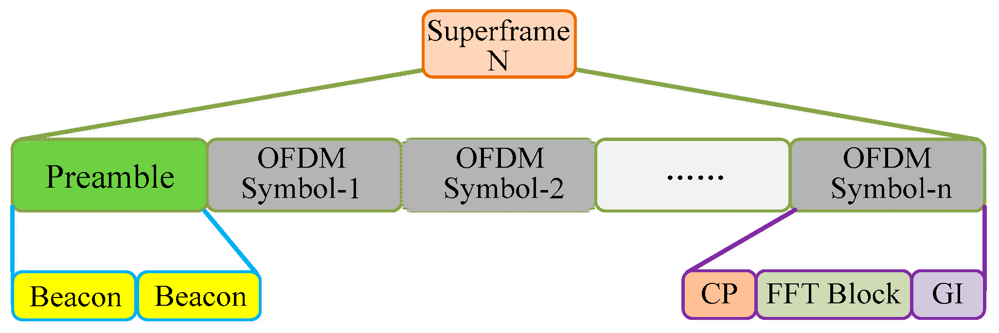
Superframe is the basic unit of the physical layer signal in the OFDM-UWB system. The head part of the superframe is filled with a preamble sequence which contains two identical beacon sequences. Each OFDM symbol consists of a cyclic prefix (CP), an FFT block, and a guard interval (GI). The superframe structure is shown in Figure 2.
The training sequence used in the system is a PN sequence, which is the longest nonlinear shift register sequence with excellent autocorrelation properties. The beacon sequence is a band-limited pseudo-random signal whose expression can be written as
x B = 1 N c i = 0 N c X B [ i ] exp [ j 2 π i ( Δ f ) c n ] , 0 n N ,
where x B [ i ] represents the training sequence in the frequency domain, N c is the number of subcarriers, ( Δ f ) c = f s / N c denotes the subcarrier spacing, and f s is the sampling frequency.

3.2. Low-Resolution Quantization Scheme

In view of the good reliability and excellent BER performance of Gray code [28], we consider the QPSK modulated signal with Gray code through an additive white Gaussian noise (AWGN) channel. For the convenience of analysis, a K -level uniform quantizer Q is used to process the received signal. The low-resolution quantization model is shown in Figure 3.
The quantized output of the AWGN channel can be expressed as
Y = Q ( R ) = Q { ( R ) } + j Q { ( R ) } ,
where R is the received signal, Y is the quantized output, Q ( ) denotes a quantization function, and ( ) and ( ) represent the real part and imaginary part, respectively. Assuming the quantization resolution is b bits, we characterize the ADC by a set of 2 b + 1 quantization thresholds τ b = { τ 0 , τ 1 , τ 2 b } , such that = τ 0 < τ 1 < τ 2 < τ 2 b = , and a set of 2 b quantization labels L b = { 0 , 1 , 2 b 1 } where i ( τ i , τ i + 1 ] . The function Q ( ) of b bits can be expressed by mapping relation Q b ( ) : C N Ω b N , which maps the received signal r n , t to the quantized output y n , t in the following way: if { R n , t } ( τ k , τ k + 1 ] and { R n , t } ( τ l , τ l + 1 ] , then y n , t = k + j l .
It can be seen from Equation (10) that the quantization distortion is caused by the fact that the low-resolution quantization changes the amplitude of the real and imaginary parts of the signal. Particularly in the case of one-bit, the quantization distortion can severely deteriorate the information of the signal. To minimize the impact of quantization, we define the quantization distortion as
e n , t = Q b ( R n , t ) ξ R n , t .
In Equation (11), the proportional coefficient ξ is used to minimize the quantization distortion variance E = Ε [ | e n , t | 2 ] . From the Wiener minimization solution [29], ξ can be expressed as
ξ = Ε [ R n , t * Q b ( R n , t ) ] Ε [ | R n , t | 2 ] .

3.3. Feedback-Based Synchronization Scheme with Low-Resolution ADCs

Assuming the received sequence is R [ n ] , then R [ n ] can be represented as
R [ n ] = R B [ n ] + N 0 ,
where R B [ n ] is a transmitted sequence, and N 0 donates a white complex Gaussian noise signal with zero mean and variance σ 2 . In general, we make the sampling clock error Δ t s = 0 , so we can respectively express the two training sequences (beacon) contained in the R [ n ] as
r B 1 [ n ] = x B 1 [ n ] exp [ j ( 2 π Δ f c n T s + Δ φ ) ] + η 1 [ n T s ] ,
r B 2 [ n ] = x B 2 [ n ] exp { j [ 2 π Δ f c ( n + N B ) T s + Δ φ ] } + η 2 [ n T s ] ,
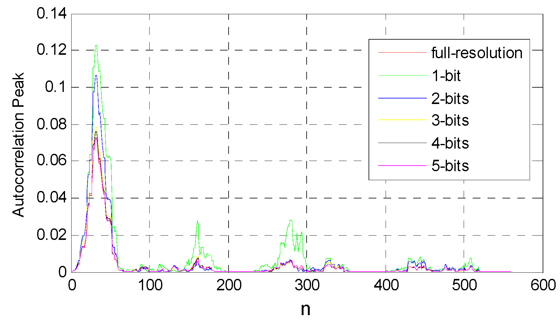
where Δ f c is the carrier frequency offset, T s is the sampling period, Δ φ denotes the phase delay, N B is the length of the training sequence, n = 0 , 1 , 2 N B 1 . η 1 and η 2 are Gaussian noise, and x B 1 [ n ] and x B 2 [ n ] represent the first half and the second half of the sequence (preamble), respectively. Therefore, we can use a 2 N B -point sliding window to sample the received signal, and then the similarity between the first N B -point samples and the last N B -point samples can be computed by an autocorrelation property. The similarity is maximized when the sliding window moves to the starting point of the OFDM symbol. The experimental results in Figure 5 show that the autocorrelation of the PN sequence is not changed by low-resolution quantization. Thus, we first consider the symbol-timing synchronization with one-bit ADCs. In our system, we can define a function of the one-bit ADCs operator as
r = sgn ( R [ n ] ) = sgn ( R B [ n ] + N 0 ) ,
where sgn ( ) is the signum function applied separately to the real and imaginary parts, N 0 is a statistically independent Gaussian noise, and r i { 1 + j , 1 j , 1 + j , 1 j } , 0 i N B 1 .
Since x B 1 is identical to x B 2 , the relationship between the autocorrelation and the location of the starting point can be expressed as
d ^ = arg max d { n = 0 N B 1 sgn ( R [ n + d ] ) sgn ( R * [ n + d + N B ] ) } = arg max d { n = 0 N B 1 | sgn ( x B 1 [ n ] ) | 2 }
where d ^ is the starting point of the OFDM symbol. Considering the case of multi-bit quantization, we normalize the received sequence R [ n ] and pass the normalized sequence through the multi-bit ADCs. In the sliding window, since the phase difference between the first N B -point samples and the corresponding last N B -point samples caused by CFO can be computed by an autocorrelation property, we can get the autocorrelation at the starting point d ^ as follows:
B exp ( j ϕ ) | d = d ^ = ρ 2 n = 0 N B 1 y B 1 [ n ] y B 2 * [ n + N B ] | d = d ^ ,
where y B 1 [ n ] and y B 2 [ n ] are elements of the quantized output in the case of multi-bit quantization, ϕ is the phase difference, and ρ is a normalization factor. For ϕ = 2 π Δ f c N B T s , the expression of frequency offset estimation module under low-resolution quantization can be given by
Δ f c = arg [ B exp ( j ϕ ) | d = d ^ ] 2 π B s N B ,
where arg ( ) represents the angle function, B s is the bandwidth of OFDM signal, and B s = 1 / T s . The mean-square error (MSE) of frequency offset estimation with low-resolution ADCs can be further given by
M S E b = 1 n i = 1 n ( Δ f c ε ) 2 ,
where ε is the normalized CFO. It is not difficult to see from Equation (10) that, when the amplitudes of the real and imaginary parts of the signal R [ n ] are close to zero, these small amplitude signals are over-amplified by low-resolution ADCs. In particular, in the case of one-bit quantization, the numerical result given by Equation (18) for estimating the frequency offset is generally not available due to its large error. Therefore, we adopt multi-bit quantization in the frequency offset estimation module. The synchronization framework with low-resolution ADCs is shown in Figure 4.
The advantage of the Schmidl and Cox (S&C) algorithm [30] is that it is not affected by frequency offset when it is used for frame synchronization or symbol synchronization. No matter how much the frequency offset is, the phase difference between the sampling points is a fixed value when the sampling interval is constant [31]. This is why we chose the S&C algorithm for analysis in the context of low-resolution quantization. This characteristic was advantageous to us for handling timing synchronization and carrier synchronization separately.

4. System Analysis and Simulation Results

4.1. Simulation System Parameters

The simulation parameters are shown in Table 1.

4.2. Quantization Effects of Timing Synchronization

In Figure 5, we plot the autocorrelation property for different quantization resolutions. We can see from Figure 5 that each curve has a maximum value at the same location. This means that the autocorrelation of the PN sequence is not affected by low-resolution quantification. Since the starting point of the OFDM symbol is determined based on the location at which the maximum autocorrelation property occurs, we can conclude that the performance of timing synchronization is not degraded by low-resolution quantization. As shown in Figure 5, with the increase of quantization resolution, the peak of each curve decreases gradually. Among these curves, the peaks under low-resolution quantization are all above those at full resolution. The reason for this phenomenon is because the small amplitude signal is amplified by the low-resolution ADCs. Furthermore, the lower the resolution is, the more serious the signal amplitude is amplified; thus, the peak under one-bit is the highest compared to other cases. Combining the above analysis, we can see that the timing synchronization based on one-bit is achievable. Therefore, the simulation results and analysis below are obtained by the frequency offset estimation module after the timing synchronization with one-bit ADCs is completed.

4.3. BER and MSE with Low-Resolution ADCs

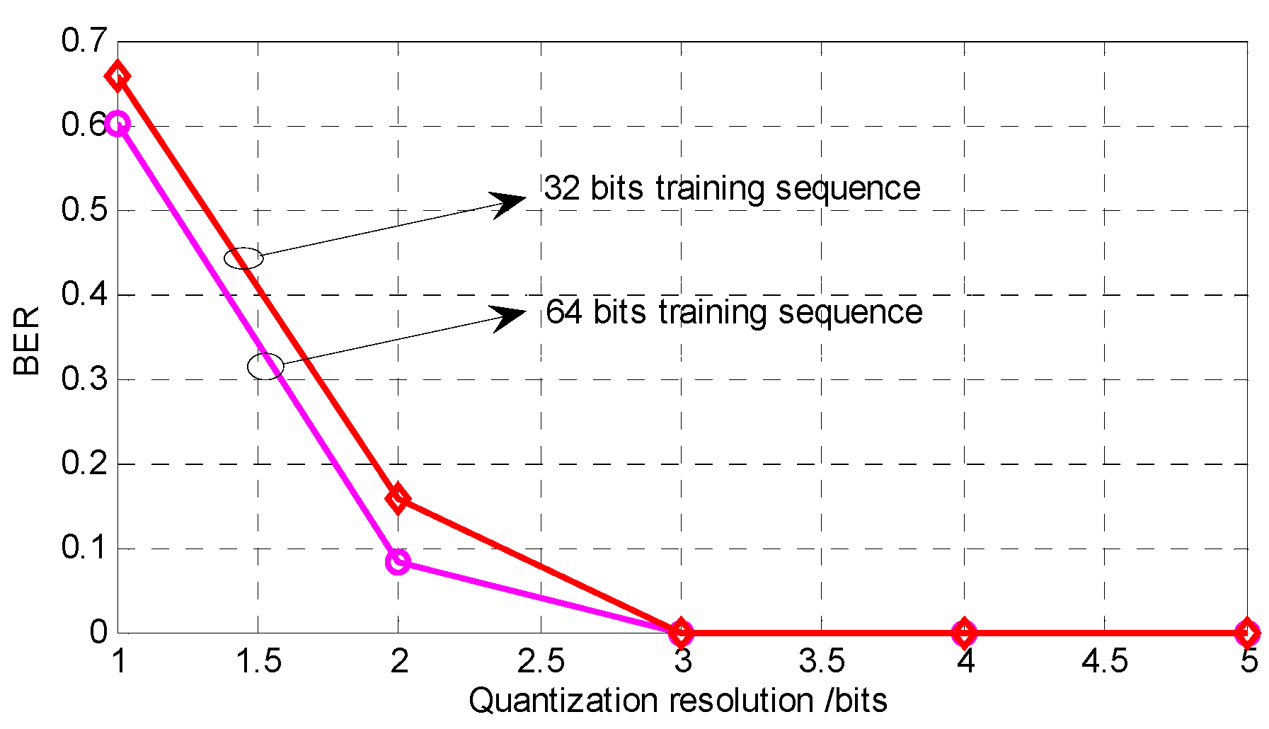
Referring to the framework shown in Figure 4, we firstly implemented the timing synchronization under one-bit quantization and then fed the starting point d ^ back to the frequency offset estimation module. After completing the above operations, we simulated the BER performance of the frequency offset estimation module at different quantization resolutions. As shown in Figure 6, we found that the BER of the frequency offset estimation module was gradually reduced as the quantization resolution increased. When the resolution was larger than 3 bits (including 3 bits), the BER began approaching zero infinitely. At the same time, increasing the length of the training sequence could further improve the BER performance. Therefore, we could use the 3-bit quantized signal to estimate the frequency offset in the frequency offset estimation module. However, due to the nonlinearity of low-resolution quantization and the imperfection of quantization theory, we could only get some performance comparison analysis. It is very difficult to describe the relationship between BER and quantization resolution through an equation.
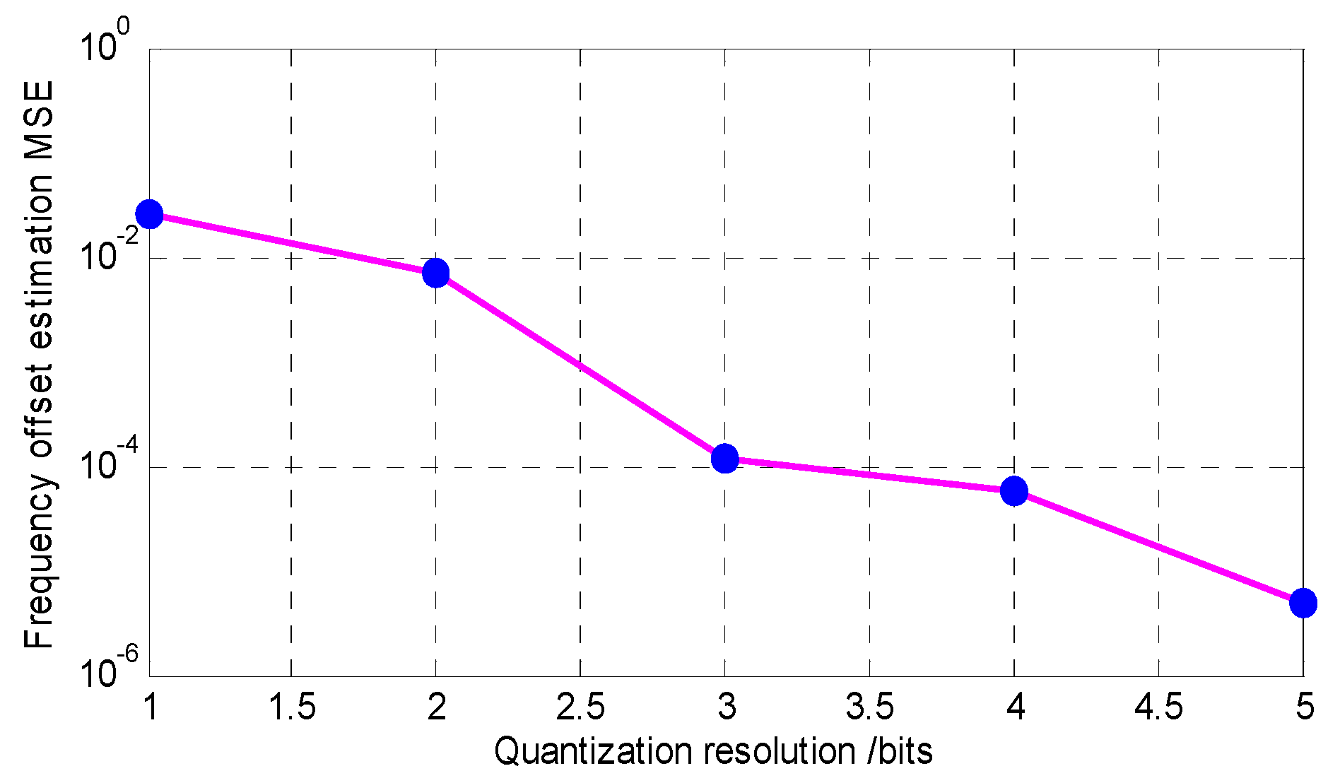
Figure 7 is a diagram of the relationship between MSE of the frequency offset estimation and quantization resolution when the length of the training sequence was 32 bits. We can see from Figure 7 that MSE gradually decreased with the increase in quantization resolution. When the quantization resolution was 3 bits, the MSE reached 10 4 order of magnitude. Moreover, the MSE under 3-bit quantization was not much different from that of the MSE under 4-bit quantization. Since the power consumption of ADC is proportional to 2 b , where b is the bit width of ADC [32], we wanted the quantization resolution to be as low as possible. In general, communication efficiency and power consumption are mutually constrained. Synthesizing the theoretical analysis and simulation results, we found that the efficiency and power consumption could be well balanced when the quantization resolution was 3 bits.

4.4. Constellation Comparison

In order to more intuitively display the function of the frequency offset estimation module, we simulated the constellation of the demodulated signal. The constellation diagram without the frequency offset estimation module is shown in Figure 8a. Since FFO destroys the orthogonality between subcarriers, we can observe that FFO caused ICI and rotation of constellation. More seriously, the rotation of the constellation leads directly to a decision error in demapping. Thus, we also simulated the BER of the corresponding constellation. The numerical results show that the BER of Figure 8a was 0.6615 when the system did not perform carrier synchronization. Through the above analysis, it can be concluded that the performance loss caused by the CFO to the OFDM system was very huge. When a frequency offset estimation module with 3-bit ADCs was added to the system, the constellation diagram was as shown in Figure 8b.
In Figure 8b, we can clearly see that the constellation points were well distributed in the polar coordinate system compared to Figure 8a. Due to the addition of the frequency offset estimation module, the system could appropriately overcome the performance degradation caused by CFO. Therefore, from the comparison of the simulation results in Figure 8a,b, we illustrate that it is feasible to perform frequency offset estimation at low resolution.

4.5. Performance Analysis

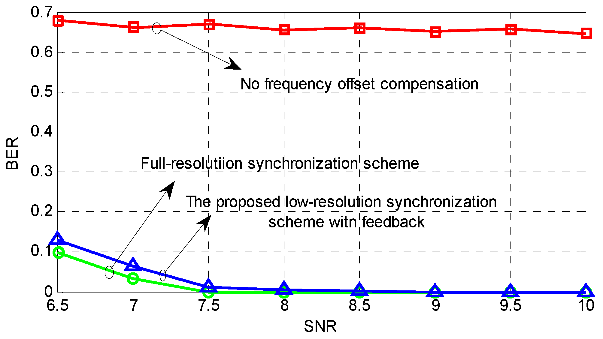
In this section, we simultaneously simulated the BER of system under the presence of a no frequency offset estimation module, a frequency offset estimation module with 3-bit ADCs, and a frequency offset estimation module with full-resolution ADCs. In all cases, the length of the training sequence was 32 and the normalized CFO ε was 0.2. In the first case, it can be seen from Figure 9 that the BER of the system did not decrease as the signal-to-noise ratio (SNR) increased. Therefore, when the CFO exists, it is not feasible to increase the SNR to improve the BER performance without performing the frequency offset compensation. In the latter two cases, we can clearly see that the BER decreased with the increase in SNR, and the BER was infinitely close to zero when SNR >8 dB. At the same time, we can also notice that the performance of the proposed synchronization scheme with low-resolution ADCs was not as good as that of the synchronization scheme under full-resolution quantization; however, their performance is comparable. Since low-resolution quantization additionally introduces the quantization noise, this inevitably results in performance loss. However, it is worthwhile to achieve significant improvements in power consumption at the expense of performance over an acceptable range. For the synchronization scheme with full-resolution ADCs, this method involved complex cyclic summation, and the power consumption of full-resolution ADCs was enormous. In our proposed approach, the symbol timing under one-bit could greatly reduce the computational complexity, and the frequency offset estimation module only needed to perform a sequence autocorrelation operation at the starting point d ^ . Compared with the full-resolution synchronization scheme, the proposed synchronization scheme has lower complexity and could effectively reduce the power consumption brought by ADCs.

5. Conclusions

In this paper, we verified the principle that the autocorrelation of the PN sequence was not affected by low-resolution quantization. With the help of this property, we introduced a novel synchronization framework which consists of two parts: one is the timing estimator with one-bit ADCs, and the other is the CFO estimator with multi-bit ADCs. The proposed scheme has lower complexity and can significantly reduce power consumption due to the use of low-resolution ADCs. Moreover, the proposed method was shown to be comparable to the performance of the full-resolution scheme. In our future work, we will explore the applicability of the proposed framework to other modulation schemes and improve the dynamic range of the signal. Given the low complexity of the framework, the future goal is to implement the proposed scheme on the DSP.

Author Contributions

Data curation, J.L.; formal analysis, Z.L.; funding acquisition, Z.L.; methodology, J.L.; software, J.L.; supervision, X.X.; validation, X.X.; writing—original draft, J.L.; writing—review & editing, Z.L. and X.X.

Funding

The paper was supported by the National Natural Science Foundation of China (No. 61801319, No. 61871422), the Opening Project of Artificial Intelligence Key Laboratory of Sichuan Province (No. 2017RZJ01), the Opening Project of Key Laboratory of Higher Education of Sichuan Province for Enterprise Informationalization and Internet of Things (No. 2017WZJ01), the Sichuan University of Science and Engineering Talent Introduction Project (No. 2017RCL10, No. 2017RCL11), the Education Agency Project of Sichuan Province (No. 18ZB0419), the Major Frontier Project of Science and Technology Plan of Sichuan Province (No. 2018JY0512), and the Sichuan Institute of Technology Graduate Innovation Foundation (No. y2018036).

Conflicts of Interest

The authors declare no conflict of interest.

References

  1. Andrews, J.G.; Buzzi, S.; Choi, W.; Hanly, S.V.; Lozano, A.E.; Soong, A.C.K.; Zhang, J. What Will 5G Be? IEEE J. Sel. Areas Commun. 2014, 32, 1065–1082. [Google Scholar] [CrossRef]
  2. Shen, X.; Guizani, M.; Qiu, R.C.; Le-Ngoc, T. Ultra-Wideband Wireless Communications and Networks; John Wiley & Sons, Inc.: Hoboken, NJ, USA, 2006. [Google Scholar]
  3. Lee, J.S.; Su, Y.W.; Shen, C.C. A comparative study of wireless protocols: Bluetooth, UWB, ZigBee, and Wi-Fi. In Proceedings of the IECON 2007—33rd Annual Conference of the IEEE Industrial Electronics Society, Taipei, Taiwan, 5–8 November 2007. [Google Scholar]
  4. Porcino, D.; Hirt, W. Ultra-wideband radio technology: Potential and challenges ahead. IEEE Commun. Mag. 2003, 41, 66–74. [Google Scholar] [CrossRef]
  5. Tatsis, G.; Votis, C.; Raptis, V.; et al. Performance of UWB-Impulse Radio Receiver Based on Matched Filter Implementation with Imperfect Channel Estimation. In American Institute of Physics Conference Series; American Institute of Physics: College Park, MD, USA, 2010. [Google Scholar]
  6. Tatsis, G.; Christofilakis, V.; Votis, C.; et al. BER Performance of an Ultra-Wideband Impulse Radio Correlator Receiver. Wseas Trans. Inf. Sci. Appl. 2011, 8, 401–406. [Google Scholar]
  7. Ranjan, M.; Larson, L.E. A Low-Cost and Low-Power CMOS Receiver Front-End for MB-OFDM Ultra-Wideband Systems. IEEE J. Solid-State Circuits 2007, 42, 592–601. [Google Scholar] [CrossRef] [Green Version]
  8. Yue, G.; Ge, L.; Li, S. Analysis of ultra wideband signal interference to DSSS receiver. In Proceedings of the IEEE Workshop on Signal Processing Advances in Wireless Communications, Rome, Italy, 15–18 June 2003. [Google Scholar]
  9. Rappaport, T.S.; Sun, S.; Mayzus, R.; Zhao, H.; Azar, Y.; Wang, K.; Wong, G.N.; Schulz, J.K.; Samimi, M.; Gutierrez, F. Millimeter Wave Mobile Communications for 5G Cellular: It Will Work! IEEE Access 2013, 1, 335–349. [Google Scholar] [CrossRef] [Green Version]
  10. Angelis, C.T.; Chronopoulos, S.K. System Performance of an LTE MIMO Downlink in Various Fading Environments. In Ambient Media and Systems; Springer: Berlin/Heidelberg, Germany, 2011. [Google Scholar]
  11. Larsson, E.G.; Edfors, O.; Tufvesson, F.; Marzetta, T. Massive MIMO for Next Generation Wireless Systems. IEEE Commun. Mag. 2013, 52, 186–195. [Google Scholar] [CrossRef]
  12. Jiang, T.; Wu, Y. An Overview: Peak-to-Average Power Ratio Reduction Techniques for OFDM Signals. IEEE Trans. Broadcast. 2008, 54, 257–268. [Google Scholar] [CrossRef]
  13. Lim, J.; Myung, H.G.; Oh, K.; Goodman, D.J. Channel-Dependent Scheduling of Uplink Single Carrier FDMA Systems. In Proceedings of the Vehicular Technology Conference, Montreal, QC, USA, 25–28 September 2006; pp. 1–5. [Google Scholar]
  14. Tsiropoulou, E.E.; Kapoukakis, A.; Papavassiliou, S. Energy-efficient subcarrier allocation in SC-FDMA wireless networks based on multilateral model of bargaining. In Proceedings of the IFIP Networking Conference, Brooklyn, NY, USA, 22–24 May 2013; pp. 1–9. [Google Scholar]
  15. Chronopoulos, S.K.; Tatsis, G.; Raptis, V.; Kostarakis, P. Enhanced PAPR in OFDM without Deteriorating BER Performance. Int. J. Commun. Netw. Syst. Sci. 2011, 4, 164–169. [Google Scholar] [CrossRef]
  16. Chronopoulos, S.K.; Christofilakis, V.; Tatsis, G.; Kostarakis, P. Reducing Peak-to-Average Power Ratio of a Turbo Coded OFDM. Wirel. Eng. Technol. 2012, 3, 195–202. [Google Scholar] [CrossRef]
  17. Murmann, B. ADC Performance Survey 1997–2013. Available online: https://web.stanford.edu/~murmann/adcsurvey.html (accessed on 7 December 2018).
  18. Singh, J.; Madhow, U. Phase-Quantized Block Noncoherent Communication. IEEE Trans. Commun. 2013, 61, 2828–2839. [Google Scholar] [CrossRef]
  19. Sobel, D.A.; Brodersen, R.W. A 1 Gb/s Mixed-Signal Baseband Analog Front-End for a 60 GHz Wireless Receiver. IEEE J. Solid-State Circuits 2009, 44, 1281–1289. [Google Scholar] [CrossRef]
  20. Wadhwa, A.; Madhow, U. Near-Coherent QPSK Performance with Coarse Phase Quantization: A Feedback-Based Architecture for Joint Phase/Frequency Synchronization and Demodulation. IEEE Trans. Signal Process. 2016, 64, 4432–4443. [Google Scholar] [CrossRef]
  21. Chronopoulos, S.K.; Votis, C.; Raptis, V.; Tatsis, G.; Kostarakis, P. In depth analysis of noise effects in orthogonal frequency division multiplexing systems, utilising a large number of subcarriers. In Proceedings of the AIP Conference Proceedings, La Herradura, Spain, 13–17 September 2010; Volume 1203, pp. 967–972. [Google Scholar]
  22. Sklar, B. Digital Communications: Fundamentals and Applications; Publishing House of Electronics Industry: Beijing, China, 2006. [Google Scholar]
  23. Xuejian, T.; Tao, L. Principle and Application of OFDM Mobile Communication Technology; People’s Post and Telecommunications Press: Beijing, China, 2003. [Google Scholar]
  24. Tsiligkaridis, T.; Forsythe, K.W. A sequential Bayesian inference framework for blind frequency offset estimation. In Proceedings of the IEEE International Workshop on Machine Learning for Signal Processing, Boston, MA, USA, 17–20 September 2015. [Google Scholar]
  25. Xu, G.Y. Research and Implementation of Synchronization in OFDM-UWB System. Master’s Thesis, Southeast University, Nanjing, China, 2010. (In Chinese). [Google Scholar] [CrossRef]
  26. Zhang, H.; Zhao, Q.; Xu, F. Impact of integer carrier frequency offset on the performance of frequency-domain contention. Electron. Lett. 2017, 53, 970–972. [Google Scholar] [CrossRef]
  27. Minn, H. On Timing Offset Estimation for OFDM Systems. IEEE Commun. Lett. 2000, 4, 242–244. [Google Scholar] [CrossRef]
  28. Chronopoulos, S.; Christofilakis, V.; Tatsis, G.; Kostarakis, P. Performance of Turbo Coded OFDM under the Presence of Various Noise Types. Wirel. Pers. Commun. Int. J. 2016, 87, 1319–1336. [Google Scholar] [CrossRef]
  29. Mollen, C.; Choi, J.; Larsson, E.G.; Heath, R.W. Performance of the Wideband Massive Uplink MIMO with One-Bit ADCs. IEEE Trans. Wirel. Commun. 2016, 16, 87–100. [Google Scholar] [CrossRef]
  30. Schmidl, T.M.; Cox, D.C. Robust frequency and timing synchronization for OFDM. IEEE Trans. Commun. 2002, 45, 1613–1621. [Google Scholar] [CrossRef]
  31. Cho, Y.S.; Kim, J.; Yang, W.Y.; Cho, Y.S. MIMO-OFDM Wireless Communications with MATLAB; Wiley: Hoboken, NJ, USA, 2010. [Google Scholar]
  32. Chiu, Y.; Nikolic, B.; Gray, P.R. Scaling of analog-to-digital converters into ultra-deep-submicron CMOS. In Proceedings of the IEEE Custom Integrated Circuits Conference, San Jose, CA, USA, 21 September 2005. [Google Scholar]
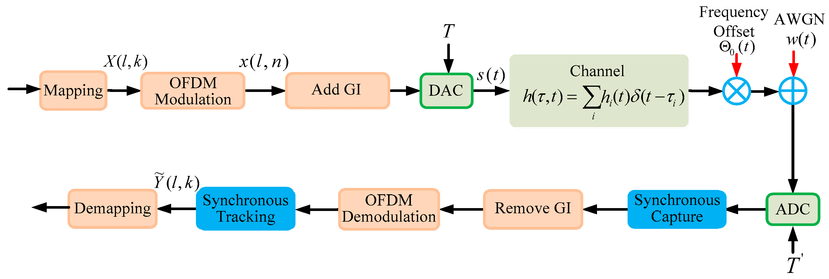
Figure 1. Orthogonal frequency division multiplexing ultra-wideband (OFDM-UWB) baseband transmission model.
Information 09 00313 g001
Figure 2. Superframe structure.
Information 09 00313 g002
Figure 3. Low-resolution quantization mode.
Information 09 00313 g003
Figure 4. Synchronization framework with low-resolution analog-to-digital converters (ADCs).
Information 09 00313 g004
Figure 5. Autocorrelation curve at low resolution.
Information 09 00313 g005
Figure 6. Error rate curve with low resolution.
Information 09 00313 g006
Figure 7. Mean-square error of frequency offset estimation.
Information 09 00313 g007
Figure 8. Impact of carrier frequency offset (CFO) on quadrature phase shift keying (QPSK) demodulated signal.
Information 09 00313 g008
Figure 9. Performance comparison of the synchronization schemes.
Information 09 00313 g009
Table 1. Simulation system parameters. QPSK—quadrature phase shift keying; FFT—fast Fourier transform; OFDM—orthogonal frequency division multiplexing; SNR—signal-to-noise ratio.
Subcarrier1024 (1 K Model)
ModulationQPSK
Quantization bits1/2/3/4/5
Superframe length559
FFT-points128
OFDM symbol length128
Guard interval32
Training sequence length32/64
SNR10 dB
Frequency offset ε 0.2
Channel delay1
Sampling point number8
Roll-off factor0.5