Abstract
Power talk is a method for communication among voltage control sources (VSCs) in DC microgrids (MGs), achieved through variations of the supplied power that is incurred by modulation of the parameters of the primary control. The physical medium upon which the communication channel is established is the voltage supply level of the common MG bus. In this paper, we show how to create power talk channels in all-to-all communication scenarios and implement the signaling and detection techniques, focusing on the construction and use of the constellations or arbitrary order. The main challenge to the proposed communication method stems from random shifts of the loci of the constellation symbols, which are due to random load variations in the MG. We investigate the impact that solutions that combat the effects of random load variations by re-establishing the detection regions have on the power talk rate.
1. Introduction
One of the key paradigm shifts in the smart grid (SG) [1,2,3] is the introduction of the concept of microgrid (MG), which emerged as a result of the penetration of distributed energy resources (DERs), i.e., small-scale distributed generators (DGs), including renewables and energy storage systems (ESSs). MGs are clusters of DERs and loads that span relatively small geographical areas (e.g., a single suburban neighborhood), which can operate connected to the main grid or autonomously, in islanded, self-sustaining mode. An example of a simple single bus DC MG system in a basic architectural configuration is shown in Figure 1. The DER units interface the common bus through flexible power electronic converters that support digital signal processing (Figure 1); the high penetration of flexible and programmable power electronic interfaces represents a distinguishing characteristic of MGs with respect to the traditional power grid.
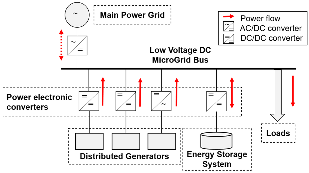
Figure 1.
Architecture of a single bus DC microgrid (MG) system.
The converters implement a set of control mechanisms with different control bandwidths to regulate the power flow in the MG and to balance the power supply and demand. The control mechanisms can be implemented in a decentralized manner, using only locally-observable quantities without any communication and providing strictly suboptimal control references (e.g., the droop control on primary control level). To enable optimal control in MGs, information exchange between units in the system is required. Traditionally, in power grid applications, external communication systems are used to provide communication capabilities, including power line communications [4,5]. The design approach where the feedback loops of the optimal controllers are enabled by an external communication system inherently reduces the reliability of the control system. In contrast, recent approaches for MG control avoid (crucially) relying on external communication networks [6,7,8] due to the availability and reliability requirements and advocate the use of the capabilities of the power electronic interfaces, foremost the capability to perform digital signal processing, as potential communication enablers. Notable examples are the bus signaling solutions that have been proposed to address specific aspects of distributed control in DC and AC MGs [8,9,10,11,12].
In this paper, we present a novel communication method designed for DC MGs termed power talk [13,14] that exploits the flexibility of the power electronic converters, enables a general digital communication interface to support optimal MG control without necessitating external hardware and has the same reliability and availability as the MG system itself. The main idea behind power talk is to modulate information in the parameters of the primary control loops that are implemented in the power electronic converters that regulate the voltage of the MG buses. This incurs bus voltage deviations that can be detected by other MG units, resulting in information transfer; the effective physical medium used for communication is bus voltage level, jointly maintained by all units in the system through primary control. As a result, the induced power talk channel exhibits some challenging properties from the communication perspective. The achievable rates of the power talk are limited by the response times of primary control loops, which are at the order of tens of milliseconds. Nevertheless, such rates may prove sufficient for the communication requirement of the MG control applications. On the other hand, power talk is, in essence, as reliable as the MG power control system itself, since all units connected to the same bus measure the bus voltage. Unlike existing bus signaling solutions whose application is limited to a narrow set of predefined coordination strategies, power talk offers a generic digital communication interface, able to support the communication demands of the majority of optimization and coordination mechanisms. As an example, the core mechanism in standard bus signaling solutions [8,9,10,11,12] relies on assigning several predefined bus voltage/frequency thresholds; whenever the thresholds are crossed, the units in the system performed predefined and coordinated actions (e.g., back up generators are turned on when the bus voltage falls beneath a predefined threshold, signaling that the system is overloaded). Evidently, the bus signaling solutions are not actually designed to transmit information messages. Thus, their implementation is application specific; this is the main limitation of existing bus signaling solutions that power talk aims to alleviate. Finally, since power talk is implemented in primary control loops, it only demands software modifications in the power electronic converters, a major advantage over other communication solutions, including standard off-the-shelf power line communications that require the installation of additional hardware.
Power talk has been introduced in [13,14], in a basic setup with two MG units and in a one-way communication scenario. The focus of [13] is on enabling reliable communication without precise knowledge of the system configuration and of the load; it is shown that using a special input symbol in the role of a pilot transforms the MG bus into some of the known communication channels. The work in [14] represents the unknown system configuration and load variations through a Thevenin equivalent, whose parameters determine the channel state and can be estimated, enabling the design of power talk constellations that perform optimally in terms of symbol error probability.
In this paper, we investigate strategies for designing multiple access power talk communication channels over the MG bus voltage. We focus on a single-bus DC MG systems with multiple control units that perform a higher layer control application, which requires exchanges of short messages, and develop a corresponding power talk framework. In particular, we investigate the construction of symbol constellations of arbitrary order at the transmitter, taking into account limitations related to power control and supply, and the construction of detection spaces used at the receiver, in which the symbol detection is performed. The above transmission and reception techniques are reviewed using the time division multiple access (TDMA) strategy for all-to-all communication setup. The main challenge of the power talk is posed by the random shifts of the constellation points due to the random variations of the loads in the system. In the paper, we assess the impact of two approaches to remedy the effects of random load variations by reestablishing the detection regions on the power talk rate. The first approach is based on periodic resetting of the detection regions, while the other is an on-demand scheme that is activated when a change in the load has been detected. We show that there is a basic trade-off between the number of communicating units, the rate of the load change and the order of modulation on one side and the attainable net rate of power talk.
The rest of the paper is organized as follows: Section 2 briefly introduces the basic terminology in MG technology, an overview of its control hierarchy with the related communication requirements and sets the design cornerstones of the power talk concept. Section 3 formalizes the operation of power talk in a TDMA framework. Section 4 introduces the concepts of signaling and detection spaces under power-related constraints and discusses the basic structural aspects. Section 5 briefly reviews the aspects of building power talk protocols that are able to cope with load changes. Section 6 presents a related evaluation of the power talk performance. Section 7 discusses the general power channel and outlines several of its interesting properties. Section 8 concludes the paper. Table 1 gives a non-exhaustive listing of the notation system and the abbreviations used throughout the manuscript.

Table 1.
List of symbols and abbreviations.
2. Brief Overview of Microgrids’ Control
Before proceeding to describe the communication channel defined by power talk and to motivate its development, we review the basic principles of control in DC MGs.
2.1. Control Architecture
The notion of control is central in MGs, especially when it operates in islanded mode. The control mechanisms in MG are usually organized in a layered, hierarchical structure [6,7] comprising three levels: primary, secondary and tertiary.
Primary control: The primary control level defines fully-decentralized mechanisms for harmonized operation of different DERs in the MG and enables adequate, load-dependent power sharing among them. Depending on the configuration of the primary control loops, the power electronically-controlled DERs fall into two categories [6,7,18]: voltage source converters (VSCs), which perform voltage regulation, and current source converters (CSCs), which do not perform voltage regulation usually configured to supply/consume constant power to/from the MG. Figure 2 shows the primary control diagram of a unit k that operates as VSC. The inner control loops (also known as zero level control) of the VSC units are usually fast (of the order of kHz), enforcing the output current and voltage to follow the predefined references, as shown in Figure 2. The bus voltage reference that is fed to the inner voltage control loop of the unit k is set according to the droop law [15,16,17,18]:
where and are the droop parameters, namely the reference voltage and the virtual resistance (also referred to as droop slope), and is the output current. Evidently, the point moves along the droop line with load changes maintaining the bus voltage within predefined limits, denoted with and , not violating the current rating of the unit and meeting the new power demand. Parameters and are controllable; in standalone mode, the value is set to the target bus voltage level, while is set to enable proportional power sharing based on the ratings of the units. In steady-state, the VSC units can be represented with equivalent voltage sources with parameters and . On the other hand, CSC units are usually constant power units that either consume or supply power. They do not implement the inner voltage control loop; instead, the reference for the inner current control loop is provided by upper control layers, and it is determined by the amount of power that the unit is willing to supply/consume. A unit can, in principle, switch between the VSC and CSC modes seamlessly; therefore, we consider only VSC units in the paper, as their task is to control the bus voltage and power sharing in the standalone mode.
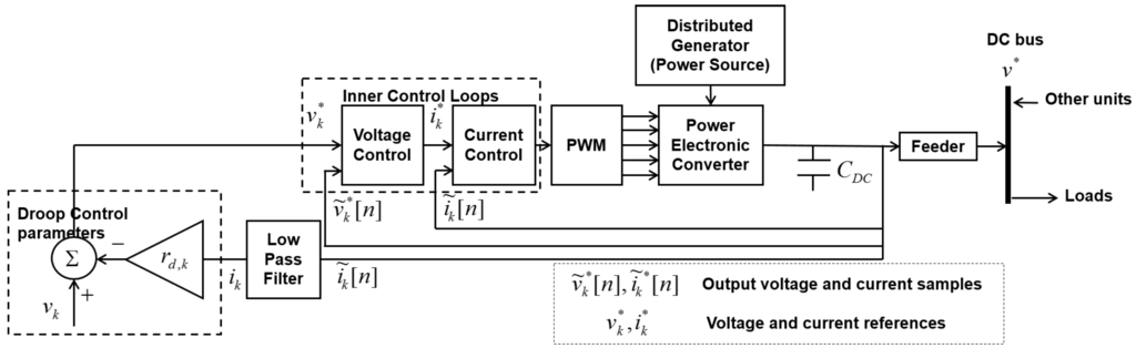
Figure 2.
Primary control loops of power electronically-controlled DER.
Secondary and tertiary controls: The primary controls, when implemented in a distributed manner using the droop method, introduce steady-state voltage deviation (refer to (1)). In light of this, the secondary control level is introduced to restore the steady-state voltage level to the nominal [6,7]. This control level is only optional, since many MG applications do not require tight voltage regulation and can handle the voltage drops introduced by the droop control. Finally, the tertiary control level deals with MG optimization (operational, economic, reliability optimization, optimal power flow, etc.) and related processing tasks (such as topology discovery, equivalent impedance estimation, etc.) [6,7]. This is the highest control level and is also active when the MG operates in grid-connected mode, enabling the transfer of energy between the MG and the main grid, determining the MG operation set points and providing the reference values for the lower controls. Although optional as the secondary level, for long-term sustainability, the presence of tertiary control is required to improve the overall efficiency and reliability of the system.
2.2. Communications for Microgrid Control
As discussed above, the primary control level works only with local voltage and current measurements and , i.e., no communication is necessary for the basic operation of the MG system. Oppositely, the tertiary (and also the secondary when present) requires information about the status of other/all units to operate properly. There is extensive literature on defining the upper level control mechanisms and optimization algorithms, including the type and the format of the information messages that should be exchanged among the units and (possibly) to a central controller [6,7,8,9,10,11,12,18,23,24]. An interesting result is presented in [24]; there, besides showing how to implement the optimal dispatch (standard control application on the tertiary level) in a distributed manner without a central controller, the authors also rigorously show that the sufficient information that is necessary to optimally assign duties to each DER is the average values of the disposable power, the power demand and the power cost in the system.
Summarizing the above discussion, it can be concluded that the resulting messages that need to be exchanged in MG systems are inherently very small. Moreover, the control messages are exchanged infrequently; as an example, the time period for which certain dispatch is valid is usually on the scale of tens of minutes or even more [24]. Therefore, we strive to design easily implementable, reliable and inexpensive communication solutions for the MG system that meets the information exchange needs of the system and avoids the need to install additional hardware.
2.3. How Power Talk Can Help
The principle of power talk communication is illustrated in Figure 3 and Figure 4. The basic idea is to modulate, i.e., change the droop control parameters and in a controlled manner. This will result in slight deviations of the output bus voltage and the output current of the unit. Since all units are connected to the same bus and measure the output bus voltage, they can detect the deviations. Thus, the process of varying the droop control parameters enables information transfer in the droop-controlled DC MG.
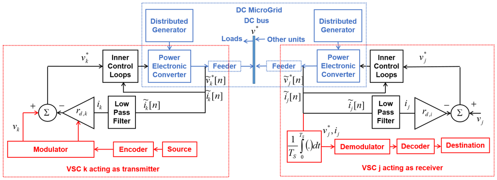
Figure 3.
Power talk: the MG as the communication system.
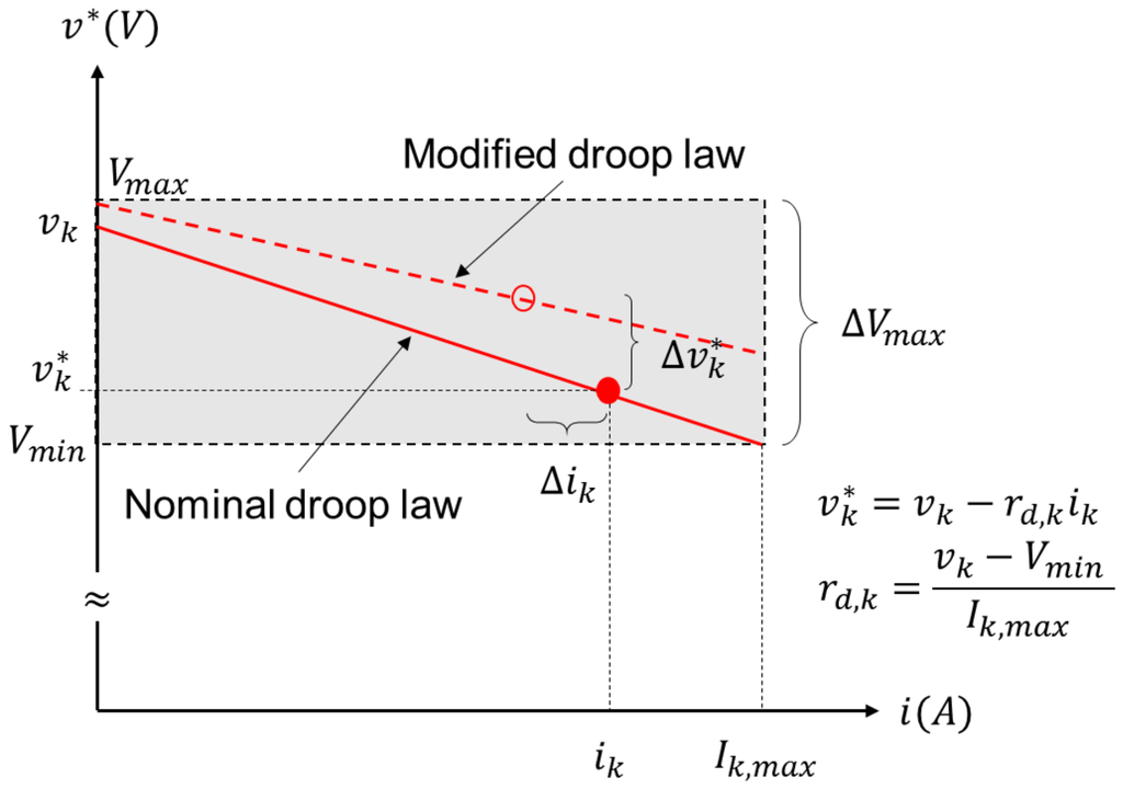
Figure 4.
Modifying the droop control.
Since droop control is valid only in the steady state, power talk is inherently a low-rate communication solution, which can be well suited for standard upper level control applications in MGs. Thus, power talk can serve as a general purpose communication enabler for the upper level control applications that trigger its activation whenever a specific control unit needs to send data to other peers in the system. As an example, power talk is activated in coordination scenarios whenever a specific unit, e.g., a renewable source or battery, experiences low levels of maximum output power and needs to notify other units in the system, which take predefined actions upon receiving the notification. Furthermore, in standard periodic economic dispatch applications, power talk will be activated at each VSC-operated DG unit periodically and to enable the exchange of dispatch-related data. The inherent advantage of power talk as opposed to the majority of the communication solutions considered for MG control is its implementation in primary control loops in the power electronic converters, circumventing the need for the installation of additional communication hardware over the MG system.
3. Power Talk in DC Microgrids
3.1. Preliminaries and Assumptions
Here, we state the assumptions used throughout the manuscript. The system model is presented in Figure 5, which is a small, localized, single bus MG system with K DER units. This means that we do not consider the effect of transmission lines, neglecting the losses. All DERs are operated as VSC units that implement droop control with reference voltages and virtual resistances , ; see (1). The units are connected to the common bus through feeder lines with negligible losses; therefore, all units observe the same bus voltage denoted with . The droop parameters in nominal mode, i.e., when the system is not power talking, are denoted with and , . are usually set to the value of the target bus voltage, while are set to enable proportional power sharing. The bus feeds a collection of loads of different types, i.e., they can be either purely resistive or constant power loads. The loads represents the variable power demand of the system that changes randomly through time. Under the above assumptions, the bus voltage in steady state is a nonlinear function in the reference voltages and the virtual resistances. We assume that the load consists of the variable resistive part denoted with r and the variable constant power part, which consumes power . The constant power load can be modeled with current source and parallel negative resistance . Writing the current balance law for the bus of the MG, we have the following (Figure 5):
where:
is the output current of VSC unit k in steady state and is uniquely determined by and . From the above equation, the bus voltage in the steady state can be written as follows:
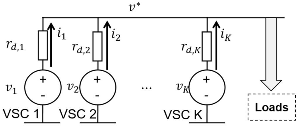
Figure 5.
Single bus DC MG system with K VSC units in the steady state.
Evidently, in the general case, the bus voltage is a nonlinear function in and . Note that is the power supplied by VSC k to the bus. The power in nominal mode, i.e., the nominal power, is denoted with .
For the reasons outlined above, the VSC units do not have knowledge of the system configuration, i.e., the states/operating points of the other MG units. This is in line with the underlying assumption used in primary control: each unit makes its primary control decisions based on locally-observable quantities, i.e., the bus voltage and the output current . Therefore, we develop power talk using the concept of detection space for each VSC unit k (see Section 4.2) as a local map of all possible values for the bus voltage and output current combinations when the system is in power talk mode.
To test the performance of the developed techniques, we use PLECS integrated with Simulink as the standard simulation tool for testing the performance of power electronically-controlled systems. In the simulation, we use booster converters operated as VSCs with an output current and voltage sampling frequency (usually of the order of kHz). Specifically, we simulate a low voltage DC MG system with allowable voltage deviation on the main bus . The current ratings of the DER units are denoted with . In the simulation, we assume that the loads can be represented with pure resistance ; however, we note that the developed techniques are applicable to any type of load, since the structure of the detection space is independent of the load types. We assume that the time axis is slotted, with slot duration . In each slot, the VSC units modify their droop control parameters to transmit information. The slot duration is assumed to be 10 ms, which is the duration that allows the bus to reach steady state. We assume that all units maintain synchronization at the slot level. Finally, we assume the all-to-all communication scenario where each unit transmits data to all other units. The values of the parameters used in the simulation are summarized in Table 2.
Table 2.
DC MG parameters simulated with PLECS.
3.2. All-to-All Power Talk: Time Division Multiple Access
We assume that the scheduling of the units is done in some predetermined manner, such that in each time slot, only one VSC transmits information over the MG, while the rest operate in the nominal mode, performing the role of receivers. The transmitting VSC inputs power talk symbols on the shared bus, while the receiving VSCs at the same time observe the corresponding output symbols.
3.2.1. Input Symbols
Denote the droop parameters of VSC k as the input :
When transmitting, VSC k chooses from Q different droop combinations , where every droop combination represents a combination of transmit bits, denoted with :
We refer to combination as a power talk input symbol. Note that the mapping (6) can be done arbitrarily on a VSC basis; for the sake of simplicity in the rest of the paper, we focus on the case where all units use the same symbols for signaling:
In principle, the symbols can be also chosen arbitrarily, as long as they comply to the operational constraints, as elaborated in Section 4.1. Without losing generality, we assume that the input symbols and the corresponding mappings are chosen to satisfy the following condition when unit k transmits and all others operate in a nominal mode:
, while the Hamming weights of satisfy:
is the supplied power to the bus by VSC k when using the droop control combination while all other units use ; is the supplied power when all units operate in nominal mode. Thus, VSC k inserts more power than nominally in the slot when transmitting a bit combination that has a higher Hamming weight. As an example, consider . Then, the input symbols satisfy , and the bit to symbol mappings are as follows: “0”, “1”. As another example, fix . The input symbols satisfy , and the bit to symbol mappings are as follows: “00”, “01”, “10”, “11”. Further, an example of a power talk symbol constellation satisfying (8) is the following: keep the virtual resistances fixed to their nominal values, i.e., , and use the following reference voltage constellation:
i.e., the reference voltage constellation is antipodal with respect to . is a small term (usually or even less for a modulation of higher order) chosen to satisfy (7). Figure 6 shows the bus voltage and the output current in an example system of two VSC units that use (10) with . Evidently, the main impairment is the sporadic, random load variations.
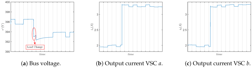
Figure 6.
TDMA-based binary power talk: two VSC units (obtained with PLECS simulation of the system shown in Figure 5, Ω, V, Ω, V, V, Ω changing to Ω).
The subsequent sections present the concept of detection space and show how to design effective detection mechanisms by observing the output voltage and current from each unit locally (i.e., by observing the waveforms shown in Figure 6).
3.2.2. Output Symbols
The receiving units j, , use the nominal droop parameter combination and locally observe a voltage and current combination, denoted as the output symbol :
where denotes the time average of y over a single slot that is obtained by unit j. Each is associated with the average output power , which depends on: (i) the nominal droop parameters of VSC j; (ii) the droop parameters of the other VSC unit including the transmitting one; and (iii) the momentary power demand of the loads. Assume that the loads do not change during the slot. Then, by measuring its own supplied power , VSC j can infer which droop parameter combination is the input of the transmitting unit. This is equivalent to tracking the point in the local diagram, as it determines how much power VSC j is providing. Henceforth, we refer to the diagram as the detection space. Since the local output is determined by , we use the following notation for TDMA power talk:
where is a receiving unit and is the information bit block represented by input symbol q and transmitted by VSC k. Figure 7 illustrates the detection spaces for a system of two VSCs (), denoted with VSC a and VSC b, assuming that VSC a is active for and .
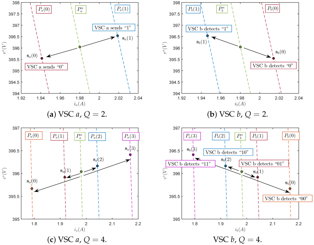
Figure 7.
diagram for TDMA-based binary power talk: two VSC units (a,b) V, V, (c,d) V, V, V, V (obtained with PLECS simulation of the system shown in Figure 5, Ω, V, Ω, Ω).
When , if VSC a inserts , it supplies less power than nominally, i.e., (“0”). At the same time, VSC b observes , detects that it supplies more than the nominal power (“0”) and concludes that VSC a is signaling “0”. Similarly, if VSC a inserts , VSC b observes (“1”), detects that (“1”) and concludes that VSC a is signaling “1”. The TDMA scheme described above can be easily generalized to an arbitrary number of units and arbitrary constellation orders. Note that we have not assumed a specific input-output relation between and ; in general, such a relation would be nonlinear. At this point, we also note that, in general, VSC j observes noisy versions of . However, in this work, the effect of the noise is neglected due to several reasons: (1) the dominant impairment of power talk as communication techniques over the power lines, implemented in primary control, is the variability of the load that changes randomly; (2) investigations have shown that the voltage/current measurements error of standard power electronic equipment available on the market is low [21,23,24,25,26]; and (3) since we use the average values of the bus voltage and the current to define the output symbol, the noise will be even further reduced due to averaging. Accounting for the Gaussian noise can rely on standard digital communication theory, while in this paper, we are focusing on the properties of a new multi-user channel that operates under power constraints.
To conclude this section, we list the main challenges in power talk as described above:
- The described communication protocol requires prior knowledge of all possible points in the detection space of VSC j. As the detailed configuration of the MG is not known a priori, these values have to be learned, e.g., in a predefined training phase, during which each VSC constructs the detection space. This is analogous to the case of channel estimation in a standard communication system where a linear relation between the input and the output can be postulated. Power talk does not use such a relation; instead, in the training phase, each unit learns each possible output in the detection space and identifies which input combination causes the respective inputs.
- The output power of a VSC can also vary as a result of the load change, which happens arbitrarily and randomly. In particular, the current values of the loads can be seen as determining the state of the system or the state of the communication channel. Whenever they change, the structure of the detection space also changes, leading to incorrect decisions at the receivers if the detection space prior to change is still used. A strategy to deal with random state variations is to periodically repeat the training phase or to provide a mechanism that tracks the state changes and re-initiates the training phase whenever a change is detected. Section 5 outlines possible strategies to deal with this challenge.
4. Constraining Power Talk
Here, we introduce the concept of signaling space to capture the effect that the operating constraints of the MG have on the power talk schemes. We then investigate the structure of the detection space and its dynamics due to the load changes, as this is vital for implementing reliable power talk solutions.
4.1. The Signaling Space
Every MG is subject to operational constraints that may not be violated. Denote by a set that consists of all operational constraints. The signaling space for Q-ary power talk is the set of all possible symbols , , that jointly satisfy the constraints in for any value of the loads:
In this paper, we focus on the bus voltage and output current constraints as the most important:
where and are the minimum and maximum allowable bus voltages and where and are the minimum and maximum output currents of VSC k; usually, , and is the current rating of the unit.
To illustrate the signaling space, assume that the load is purely resistive . Then, under the constraints (14), the steady-state model (4) and (3), the symbols when unit k is transmitting should jointly satisfy:
for and . Note that when the symbols satisfy (8), (15) and (16) are satisfied for and ; then, they are also satisfied by .
It can be shown that the signaling space given with (15) and (16) can be equivalently written as follows:
where and are the voltage and the resistance of the Thevenin equivalent as seen from the transmitting VSC, calculated for input when the load value is r. Thus, from (17) and (18), it follows that the units do not need precise knowledge of the system (i.e., the function (4)); to determine the signaling space when transmitting, they only need the equivalent response of the system at minimum and maximum load.
Further, every input symbol results in different power supplied by VSC j. To account for this effect, we introduce the relative power deviation of unit j when unit k is transmitting, respective to its supplied power when all units operate nominally:
where the averaging is performed over the load r, modeled as a random variable with some distribution . Then, the average supplied power deviation per unit δ, for TDMA-based power talk, is calculated as:
where, for given j and given k, we first average over all possible Q symbols unit k inputs; then, we also average over all k for a given j, and the final averaging is over all possible j. Finally, we introduce average power deviation limit γ, requiring that:
i.e., the average power deviation per unit w.r.t. the nominal mode of operation is bound by γ.
Figure 8 depicts the signaling space for a two-unit system, when VSC a transmits, while VSC b operates in nominal mode, for system parameters listed in Table 2 and the uniform distribution of the load . The figure also depicts the relative power deviation of VSC a, as a function of the input symbol . Evidently, increases when the input symbol is placed far from . Figure 9 shows that the signaling space and the average power deviation δ for binary power talk and have fixed droop slope and . δ is obtained by averaging as in (20) with equiprobable bits. Evidently, the available signaling spaces decrease as the number of units increases.
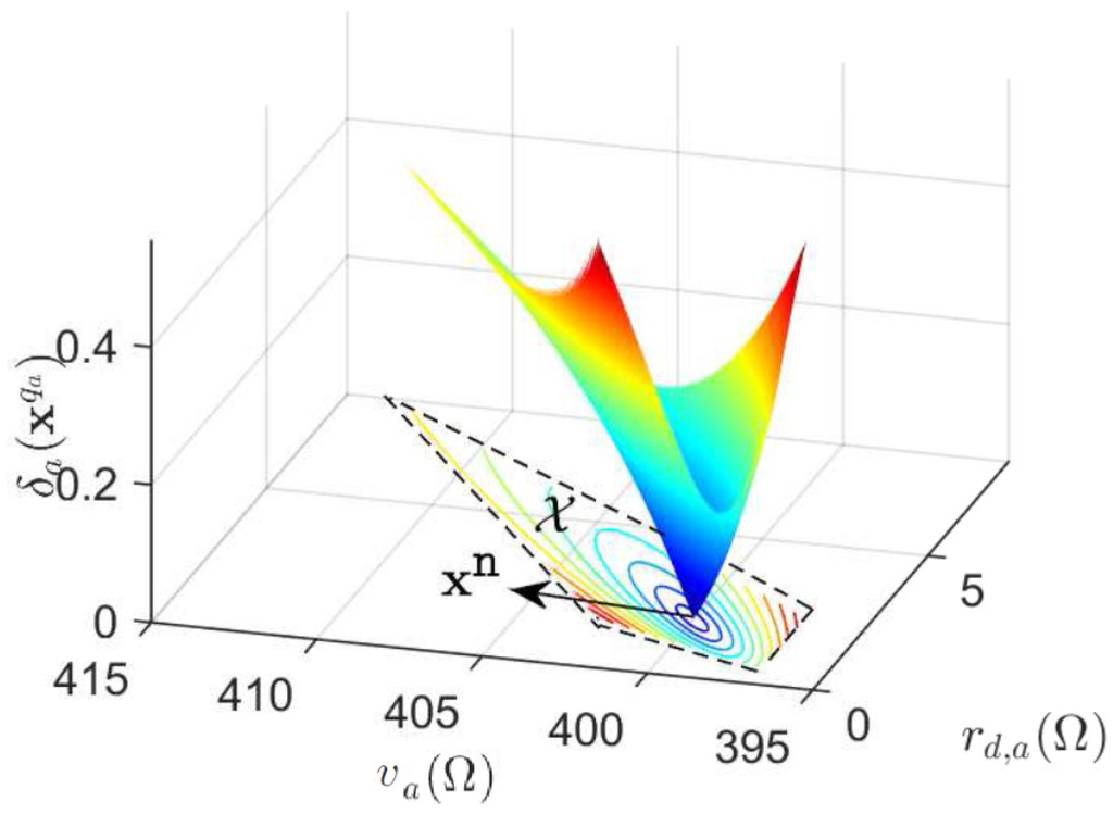
Figure 8.
The signaling space and the relative power deviation in a two-unit system.
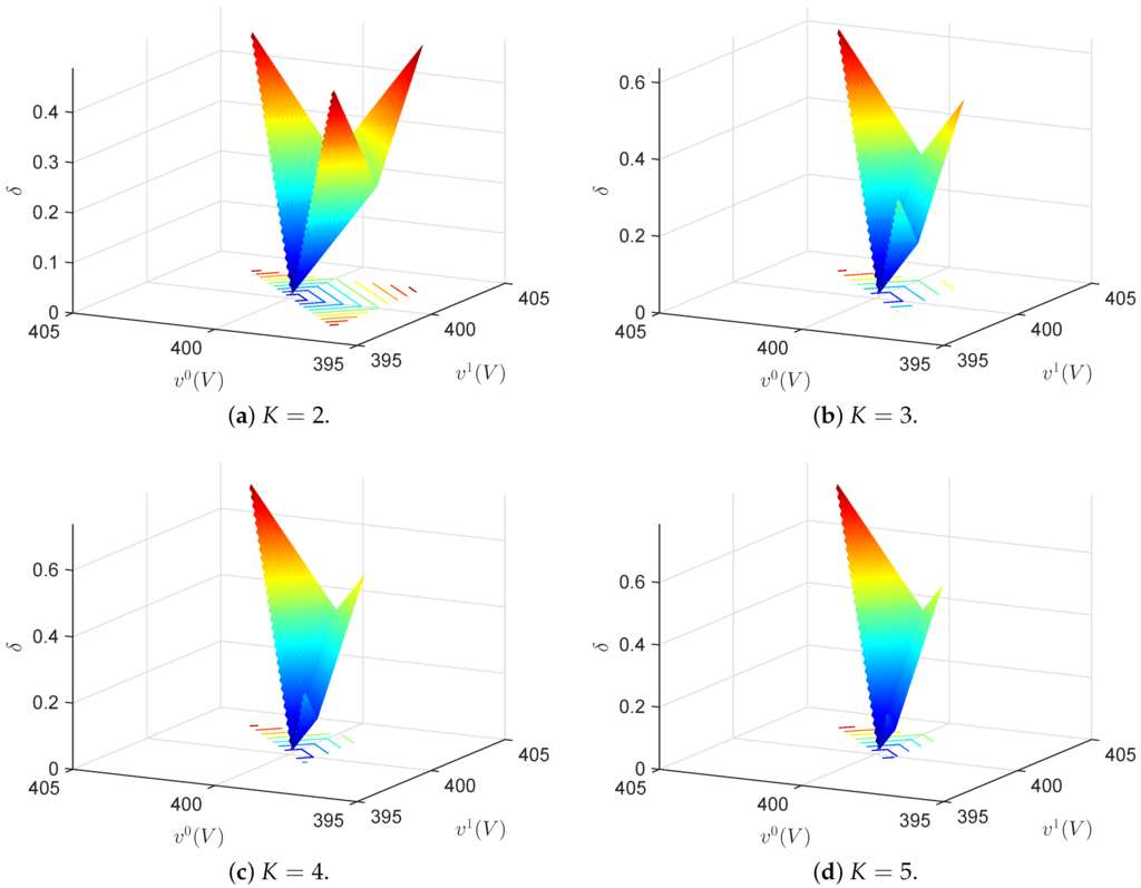
Figure 9.
The signaling space and average power deviation, , fixed constellation, Ω, equiprobable bit values.
4.2. The Detection Space
As already introduced, the detection space for receiving VSC j when VSC k is transmitting () is defined as the set of points , where is the output voltage, equal to the bus voltage when the line resistance is negligible, and is the output current of VSC j. By observing , VSC j gathers information about the symbols/powers of other units.
We outline the general structure of the detection space, illustrated in Figure 10. All outputs of VSC j lie on the line where is the symbol VSC j is inserting. When VSC k is transmitting, , and the output symbols lie on a single line, as shown in Figure 10. The actual loci of output symbols of VSC j, i.e., , are in the intersection of and , where is the output power. As the load in the system varies, the points in shift along ; see Figure 10b. Comparing Figure 10c to Figure 10a, it is apparent that under a constant average power deviation constraint, increasing the number of units reduces the distance among the symbols.
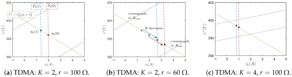
Figure 10.
The detection space of VSC j, fixed constellation, , and resistive load r. The dashed lines represent the output power , and the dashed-dotted line represents the symbol that VSC j is inserting. The loci of output symbols are on the intersection between the lines corresponding to output powers and the local inputs. As r varies, slide along the dashed-dotted lines between the bounds (dotted lines) defined by operational constraints on the load.
5. Dealing with Random Load Changes
In this section, we present techniques that complement the basic power talk operation, as described in the previous sections, required to design a fully-operational communication protocol. To evaluate their efficiency, we use the net reception rate per unit , i.e., the average number of information bits received per unit per time slot, calculated as follows:
where η is the transmission rate that is equal to, for each VSC k, and where the term reflects the fact that a VSC unit is in receiving mode times more than in transmitting mode when TDMA is used. The following bound holds:
with equality when the load is perfectly know. However, all VSCs have to maintain a layout of the detection space that matches the current value of the loads. A simple and effective strategy for the construction of the detection space is to conduct a training phase during which the units input predefined training sequences. We think of the number of time slots used for training sequences as a necessary cost in order to “learn” the respective power talk channels. We assume that each unit builds its detection space separately, in order to take into account the imperfections of the MG system, such as small resistances of the feeder lines and the common bus. Therefore, a unit has to learn Q points in its detection space for each of the remaining units. Assuming that a point is learned during M dedicated slots, the training phase length is slots. The training phase can be performed by sequential transmission of , by one of the units, while the remaining units operate nominally and construct their detection spaces.
Finally, we review potential schemes for the activation of the training phase. We assume that the rate of change of the loads in the system is much lower than the power talk signaling rate. A simple solution for training phase activation would be to perform training periodically and to update the detection spaces of the units. This is a robust and stable solution; however, load changes during the data phase might lead to lost data, which would require retransmissions. A more involved approach would be to employ a model change detector that tracks the bus voltage and, if a change is detected, initiates the training phase. Using this approach, no data are lost; however, it necessitates a model change detector with high fidelity performance since all units have to detect the load change with very high probability [28].
6. Performance Evaluation
Here, we evaluate the performance of power in terms of the net reception rate, and we show that there is an inherent trade-off between the number of units, the order of the power talk modulation and the rate of load change. We simulate a DC MG system as described in Section 3.1. We assume that the load is purely resistive and model the load changes through a Poisson process, whose intensity λ is the expected number of load changes per time slot. As the slot duration is of the order of milliseconds, one can expect that in practice. We also assume that whenever the load changes, the detection spaces are completely destroyed for all units. Thus, when the training sequences are inserted periodically, if a load change occurs in the data transmission phase, all bits after the change are assumed to be lost. This is essentially the worst case scenario, since very small load changes will cause a negligible shift of the points in the detection spaces. Additionally, since we neglect the noise, we assume a perfect model change detector for the on-demand training sequence insertion approach.
Figure 11 depicts the simulation results for the net reception rate for TDMA power talk. For a given order of modulation, the net reception rate of TDMA power talk is upper bounded with . We observe that the net reception rate decreases as the rate of load change increases. This is due to the detection space establishment cost. For the periodic insertion approach, the increase in the load change rate will result in more lost data, while with the on-demand approach, the training sequence will be inserted more frequently. Comparing Figure 11a,b to Figure 11c,d, we see that for the same rate of load changes, higher net reception rates can be achieved with the on-demand training sequence insertion approach. This is the expected result since when inserting the training sequences only when necessary, we are using the available time resources more efficiently. Additionally, from Figure 11, there exist an optimum number of units that maximizes the net reception rate for a fixed load change rate and a fixed constellation size; nevertheless, we can observe that the reduction of the net reception rate for K larger than the optimum is not dramatic. For a given load change rate, there exists an optimum number of constellation points that maximizes the net reception rate; the optimal Q increases as the load change rate decreases. Finally, with the on-demand training sequence insertion approach, we can in general use higher order constellations for a fixed number of units and a fixed load change rate and achieve higher net reception rates.
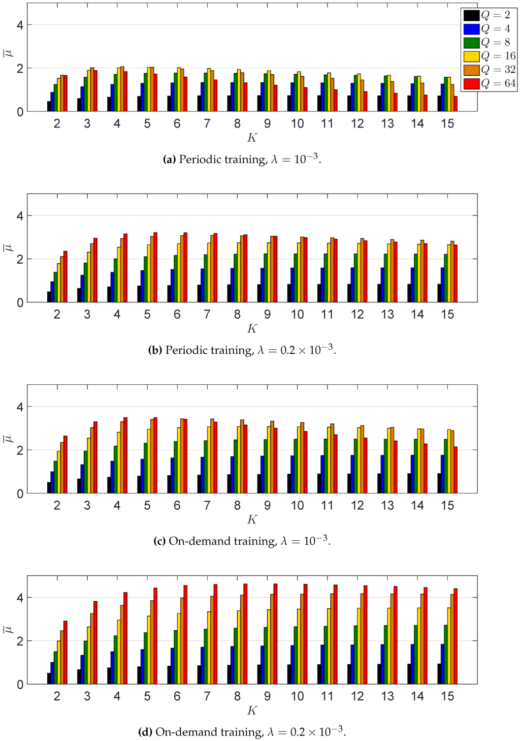
Figure 11.
Performance of TDMA power talk in terms of the net reception rate.
7. On the General Power Talk Channel Model
Finally, here, we discuss some unique aspects of the general power talk channel model, established over the voltage supply level. For a single bus DC MG system, where all units are connected to the same bus and observe the same bus voltage, the input-output relation of the channel is given by (4). As is evident, all units jointly determine the output of the channel (through their droop control parameters); on the other hand, the output also varies sporadically as the load changes, representing the main communication impairment. If the load variations are seldom, with a lower rate than the power talk communication rate, then they can be modeled as a random channel state that remains fixed during multiple transmission slots. So far, we have treated the TDMA strategy over (4), where in each slot, only one unit transmits, while all other units operate in nominal mode . In Section 4.1, we showed that when constraining the input using the signaling space, essentially all units (the transmitting and the receiving) jointly constrain the individual input of the transmitting unit; the signaling space (15) and (16), as well as the average power deviation (20) clearly illustrate this aspect. Having a joint constraint on the transmitters is a remarkable property in power talk channels created over the bus voltage level in the MG, not found in the conventional communication model, where it is common to have an individual constraint per transmitter. The property is strongly pronounced in full duplex scenarios where all units transmit and receive at the same time; in this case, the assignment of equivalent power deviation budgets for each unit will be done by solving a joint optimization problem over all droop control units in the MG.
Another major aspect of (4) is its non-linearity of in the inputs . In this paper, we presented a solution based on detection spaces; this way, we were are able to eliminate some of the issues stemming from the non-linearity of (4) and its dependence on the values of the loads. Another possible approach is to use very small droop deviations around the nominal value, i.e., with satisfying , . Then, we can linearize (4) around . This solution will significantly limit the space of all possible input combinations; nevertheless, it leads to some particularly interesting observations. Specifically, the resulting signal model is a linear combination of the input droop deviations (that carry the information in this case); however, the coefficients of the linear combination are functions of the nominal droop parameters , and their values can be modified through . This is an interesting feature of the linearized power talk channel, which opens a multitude of possibilities to optimize the performance of the power talk communication, and it is part of our ongoing work. Moreover, it can be also shown that in the linearized channel, each unit obtains its input constraint as a solution of the linear program, solved over all participating units; the coefficients of the program are also functions of , opening another possible way of optimizing the power talk channels.
8. Conclusions and Discussion
In the paper, we presented power talk, a method for communication among VSC units in a microgrid. We have shown that by modifying the parameters of the primary control loops of VSC units, it is possible to design signaling constellations that conform to the operating constraints and limits to the power deviations with respect to the nominal operation.
The main challenge of power talk is the arbitrary variations of load. We investigated the impact that the techniques that counter-effect load changes have on the power talk rate, showing that there exists a dependence between the number of communication units, constellation size and load-change rate.
The future work will focus on more advanced power talk solutions that effectively address the non-linearity of the general problem and more efficiently exploit the available communication resources. A possible approach is to let all VSC units communicate at the same time in a full duplex fashion, where each unit is at the same time a transmitter and a receiver. Our initial investigations have shown that in such a case, under mild assumptions on the input symbol constellations, the resulting power talk channel is an integer adder multiple access channel for which efficient uniquely decodable codes can be applied. Another approach would be to use linearization strategies on (4) to obtain a linear input-output model. The preliminary investigations have shown that if only the reference voltage is modulated, the droop slopes are kept fixed, and the output is linearized in the input reference voltage deviations, the resulting channel is linear with channel coefficients that depend on the droop slopes, and thus, they can be controlled. In this regard, one of our goals is to find optimal communication strategies for power talking DC MGs.
Acknowledgments
The work presented in this paper was supported in part by the EU, under Grant Agreement No. 607774 “ADVANTAGE”.
Author Contributions
Marko Angjelichinoski, Čedomir Stefanović and Petar Popovski conceived the theoretical content of the paper. Marko Angjelichinoski carried out the analysis, formulated the representations of signaling and detection spaces, carried out the simulations and analyzed the simulation data. Čedomir Stefanović and Petar Popovski proposed the investigation of the trade-off between the net reception rate of TDMA power talk, the order of the constellation, the number of communicating units and the rate of load changes. Frede Blaabjerg proposed the simulation environment, as well as provided consultations regarding the implementation details.
Conflicts of Interest
The authors declare no conflict of interest.
References
- Lasseter, R. Microgrids. In Proceedings of the IEEE Power Engineering Society Winter Meeting, New York, NY, USA, 27–31 January 2002; pp. 305–308.
- Hatziargyriou, N. Microgrids: Architectures and Control; Wiley-IEEE Press: New York, NY, USA, 2014. [Google Scholar]
- Bush, S.F. Smart Grid: Communication-Enabled Intelligence for the Electric Power Grid; John Wiley & Sons: New York, NY, USA, 2014. [Google Scholar]
- Yan, Y.; Qian, Y.; Sharif, H.; Tipper, D. A survey on smart grid communication infrastructures: Motivations, requirements and challenges. IEEE Commun. Surveys Tutor. 2013, 15, 15–20. [Google Scholar] [CrossRef]
- Galli, S.; Scaglione, A.; Wang, Z. For the grid and through the grid: The role of power line communications in the smart grid. IEEE Proc. 2011, 99, 998–1027. [Google Scholar] [CrossRef]
- Guerrero, J.; Vasquez, J.; Matas, J.; de Vicuna, L.G.; Castilla, M. Hierarchical control of droop-controlled AC and DC microgrids—A general approach toward standardization. IEEE Trans. Ind. Electron. 2011, 58, 158–172. [Google Scholar] [CrossRef]
- Guerrero, J.; Chandorkar, M.; Lee, T.; Loh, P. Advanced control architectures for intelligent microgrids; part i: Decentralized and hierarchical control. IEEE Trans. Ind. Electron. 2013, 60, 1254–1262. [Google Scholar] [CrossRef]
- Jin, C.; Wang, P.; Xiao, J.; Tang, Y.; Choo, F.H. Implementation of hierarchical control in DC microgrids. IEEE Trans. Ind. Electron. 2014, 68, 4032–4042. [Google Scholar] [CrossRef]
- Schonberger, J.; Duke, R.; Round, S. DC-bus signaling: A distributed control strategy for a hybrid renewable nanogrid. IEEE Trans. Ind. Electron. 2006, 53, 1453–1460. [Google Scholar] [CrossRef]
- Chen, D.; Xu, L.; Yao, L. DC voltage variation based autonomous control of DC microgrids. IEEE Trans. Power Deliv. 2013, 28, 637–648. [Google Scholar] [CrossRef]
- Vandoorn, T.; Renders, B.; Degroote, L.; Meersman, B.; Vandevelde, L. Active load control in islanded microgrids based on the grid voltage. IEEE Trans. Smart Grid 2011, 2, 139–151. [Google Scholar] [CrossRef]
- Sun, K.; Zhang, L.; Xing, Y.; Guerrero, J. A distributed control strategy based on DC bus signaling for modular photovoltaic generation systems with battery energy storage. IEEE Trans. Power Electron. 2011, 26, 3032–3045. [Google Scholar] [CrossRef]
- Angjelichinoski, M.; Stefanovic, C.; Popovski, P.; Liu, H.; Loh, P.; Blaabjerg, F. Power talk: How to modulate data over a DC micro grid bus using power electronics. In Proceedings of the 6th IEEE International Conference on Smart Grid Communications (SmartGridComm 2015), Miami, FL, USA, 2–5 November 2015.
- Angjelichinoski, M.; Stefanovic, C.; Popovski, P.; Blaabjerg, F. Power talk in DC micro grids: Constellation design and error probability performance. 2015; arXiv:1507.02598. [Google Scholar]
- Pogaku, N.; Prodanovic, M.; Green, T. Modeling, analysis and testing of autonomous operation of an inverter-based microgrid. IEEE Trans. Power Electron. 2007, 22, 613–625. [Google Scholar] [CrossRef]
- Mohamed, Y.-R.; El-Saadany, E. Adaptive decentralized droop controller to preserve power sharing stability of paralleled inverters in distributed generation microgrids. IEEE Trans. Power Electron. 2008, 23, 2806–2816. [Google Scholar] [CrossRef]
- Blaabjerg, F.; Chen, Z.; Kjaer, S. Power electronics as efficient interface in dispersed power generation systems. IEEE Trans. Power Electron. 2004, 19, 1184–1194. [Google Scholar] [CrossRef]
- Dragicevic, T.; Guerrero, J.; Vasquez, J.; Skrlec, D. Supervisory control of an adaptive-droop regulated DC microgrid with battery management capability. IEEE Trans. Power Electron. 2014, 29, 695–706. [Google Scholar] [CrossRef]
- Giannakis, G.; Kekatos, V.; Gatsis, N.; Kim, S.-J.; Zhu, H.; Wollenberg, B. Monitoring and Optimization for Power Grids: A Signal Processing Perspective. IEEE Signal Process. Mag. 2013, 30, 107–128. [Google Scholar] [CrossRef]
- Liang, H.; Choi, B.J.; Abdrabou, A.; Zhuang, W.; Shen, X. Decentralized Economic Dispatch in Microgrids via Heterogeneous Wireless Networks. IEEE J. Sel. Areas Commun. 2012, 30, 1061–1074. [Google Scholar] [CrossRef]
- Sangswang, A.; Nwankpa, C. Effects of switching-time uncertainties on pulsewidth-modulated power converters: Modeling and analysis. IEEE Trans. Circuits Syst. I 2003, 50, 1006–1012. [Google Scholar] [CrossRef]
- Cobreces, S.; Bueno, E.; Pizarro, D.; Rodriguez, F.; Huerta, F. Grid impedance monitoring system for distributed power generation electronic interfaces. IEEE Trans. Instrum. Meas. 2009, 58, 3112–3121. [Google Scholar] [CrossRef]
- Midya, P.; Krein, P. Noise properties of pulse-width modulated power converters: Open-loop effects. IEEE Trans. Power Electron. 2000, 15, 1134–1143. [Google Scholar] [CrossRef]
- Mazumder, S.; Nayfeh, A.; Boroyevich, D. Theoretical and experimental investigation of the fast- and slow-scale instabilities of a DC-DC converter. IEEE Trans. Power Electron. 2001, 16, 201–216. [Google Scholar] [CrossRef]
- Cavallini, A.; Montanari, G.; Cacciari, M. Stochastic evaluation of harmonics at network buses. IEEE Trans. Power Deliv. 1995, 10, 1606–1613. [Google Scholar] [CrossRef]
- Sangswang, A.; Nwankpa, C. Random noise in switching DC-DC converter: Verification and analysis. In Proceedings of the 2003 IEEE International Symposium on Circuits and Systems (ISCAS 2003), Bangkok, Thailand, 25–28 May 2003.
- Sanchez, S.; Molinas, M. Large signal stability analysis at the common coupling point of a DC microgrid: A grid impedance estimation approach based on a recursive method. IEEE Trans. Energy Convers. 2015, 30, 122–131. [Google Scholar] [CrossRef]
- Kay, S. Fundamentals of Statistical Signal Processing: Estimation Theory; Prentice-Hall: Upper Saddle River, NJ, USA, 1998. [Google Scholar]
© 2016 by the authors; licensee MDPI, Basel, Switzerland. This article is an open access article distributed under the terms and conditions of the Creative Commons by Attribution (CC-BY) license (http://creativecommons.org/licenses/by/4.0/).