Abstract
With the rapid development of intelligent transportation systems (ITSs) and Internet of Things (IoT), vehicle-mounted edge computing (VEC) networks are facing the challenge of handling increasingly growing computation-intensive and latency-sensitive tasks. In the UAV-assisted VEC network, by introducing mobile edge servers, the coverage of ground infrastructure is effectively supplemented. However, there is still the problem of decision-making lag in a highly dynamic environment. This paper proposes a deep reinforcement learning framework based on the long short-term memory (LSTM) network for trajectory prediction to optimize resource allocation in UAV-assisted VEC networks. Uniquely integrating vehicle trajectory prediction with the Twin Delayed Deep Deterministic Policy Gradient (TD3) algorithm, this framework enables proactive computation offloading and UAV trajectory planning. Specifically, we design an LSTM network with an attention mechanism to predict the future trajectory of vehicles and integrate the prediction results into the optimization decision-making process. We propose state smoothing and data augmentation techniques to improve training stability and design a multi-objective optimization model that incorporates the Age of Information (AoI), energy consumption, and resource leasing costs. The simulation results show that compared with existing methods, the method proposed in this paper significantly reduces the total system cost, improves the information freshness, and exhibits better environmental adaptability and convergence performance under various network conditions.
1. Introduction
The accelerated advancement of intelligent transportation systems (ITSs) and Internet of Vehicles (IoV) technologies has stimulated the proliferation of various emerging in-vehicle applications; examples include autonomous driving, real-time navigation, augmented reality, and multimedia content sharing, which are rapidly gaining popularity [1]. These applications are typically computationally intensive and latency-sensitive, posing severe challenges to the response speed and computing power of the network. However, since in-vehicle terminals are usually constrained by limited computing resources, storage capacity, and energy supply, relying solely on local computing often fails to meet the high reliability and low latency requirements of these applications [2].
Vehicular edge computing (VEC), a technology that deploys servers at the network edge to enable vehicle users to offload computing tasks to nearby roadside units (RSUs), has been widely recognized as an effective solution to the above challenges [3]. VEC reduces the computing burden on cellular networks by shortening data transmission distances, offering users more efficient and reliable network services. However, the traditional static deployment of edge servers still faces multiple challenges: first, in remote areas with sparse infrastructure coverage, vehicle users may be unable to access edge computing services; second, in urban congested areas with high vehicle density, limited RSU resources struggle to meet a large number of concurrent computing requests; and third, urban building obstructions may degrade signal quality, affecting the quality of service (QoS) [4].
To address these issues, researchers have proposed a UAV-assisted VEC network architecture by integrating UAVs (Unmanned Aerial Vehicles) into the VEC network [5]. Military use of UAVs has become a widespread practice globally and in civilian fields due to their advantages of easy deployment, high mobility, and strong line-of-sight (LoS) links [6,7]. In VEC networks, UAVs can serve as mobile edge servers to provide additional computing and communication services, thereby relieving the pressure on ground computing and communication resources while filling VEC network coverage gaps. Furthermore, UAV-assisted VEC systems leverage more reliable LoS links to offer flexible on-demand services and respond more promptly to user requests [8].
However, UAV-assisted VEC networks still face complex resource optimization challenges. First, the high-speed mobility of UAVs and vehicles leads to rapid changes in network topology and channel conditions; second, the randomness and burstiness of vehicle tasks make resource requirements difficult to predict; and third, UAV energy constraints severely impact the system’s continuous service capabilities [9,10]. Traditional studies focus on minimizing latency or energy consumption [11,12], or balancing the two [13,14], but rarely consider the critical metric of information timeliness, modeled by Age of Information (AoI).
The integration of AoI is innovative and critical for safety-critical applications, especially autonomous driving. Autonomous vehicles depend on real-time environmental data processed by UAV-assisted VEC nodes for decisions. Stale computation results of pedestrian dynamics or vehicle trajectories at intersections could cause incorrect speed adjustments, posing severe safety risks.
In intelligent traffic management and vehicle platooning, high AoI also matters. Stale traffic flow data may lead to mismatched signal cycles, while delayed platoon data could break synchronization and cause accidents. Traditional latency metrics cannot reflect this continuous information freshness requirement [15], making AoI a vital metric for reliability.
In response to the above challenges, Yan et al. [16] proposed a computation offloading framework based on deep reinforcement learning, which minimizes the weighted sum of AoI cost, energy consumption, and rental costs by jointly optimizing UAV trajectories, user associations, and offloading decisions. However, this approach has notable limitations: (1) it makes decisions based solely on the current state, lacking the ability to predict future network states, leading to decision lag in highly dynamic environments; (2) it overlooks the spatiotemporal correlation of vehicle movement trajectories, making it difficult to capture traffic patterns; and (3) it demonstrates insufficient adaptability to network environment changes, with room for improvement in learning efficiency and convergence.
This paper proposes a novel deep reinforcement learning framework based on LSTM trajectory prediction for resource allocation optimization in UAV-assisted VEC networks. The framework innovatively integrates vehicle trajectory prediction with the Twin Delayed Deep Deterministic Policy Gradient (TD3) algorithm to enable proactive computation offloading and UAV trajectory planning.Contrasting with previous methods, the key contributions of this paper are presented as follows:
- A novel vehicle trajectory prediction network based on an LSTM attention mechanism is designed, which accurately forecasts the future positions and task requirements of vehicles. This provides a predictive decision-making foundation for resource optimization, effectively addressing the decision-making lag issue that traditional methods face in highly dynamic environments.
- State smoothing and data augmentation techniques are proposed to effectively mitigate the impact of environmental state fluctuations on learning stability, thereby enhancing the model’s robustness against noise and uncertainty.
- An innovative mechanism is developed to integrate prediction results into the optimization decision-making process, enabling the system to adjust current decisions based on predicted future states and achieve truly proactive resource optimization.
The remainder of this paper is structured as follows: Section 2 reviews the related literature; Section 3 details the system model; Section 4 proposes a TD3-based computation offloading optimization framework integrated with LSTM prediction; Section 5 presents the simulation results and performance analysis; and Section 6 concludes this paper with suggestions for future research.
2. Related Work
This section reviews the research progress related to UAV-assisted vehicular edge computing, encompassing vehicular edge computing systems, computing offloading strategies, the application of deep reinforcement learning in resource optimization, and trajectory prediction technologies. It aims to provide a theoretical background and research foundation for the innovative work presented in this paper.
2.1. Vehicular Edge Computing and UAV-Assisted Systems
VEC has emerged as a critical approach enabling autonomous driving-related technologies for intelligent transportation systems by deploying computing resources at the network edge to deliver low-latency, high-reliability computing services to vehicle users [17,18]. Liu et al. [19] explored the application scenarios and architectural design of VEC in the Internet of Vehicles, proposing a hierarchical VEC framework. Huang et al. [20] investigated the revenue and energy efficiency optimization in VEC networks, designing a deep reinforcement learning approach to delay-constrained task offloading and resource allocation. However, traditional statically deployed VEC systems still face challenges of insufficient coverage and uneven resource allocation in complex road environments.
In recent years, UAV-assisted mobile edge computing (UAV-MEC) has gained significant attention as an emerging technological paradigm [21]. Huda et al. [22] provided a comprehensive survey of UAV-MEC systems, analyzing their architectural design, resource management, and application scenarios. Wang et al. [23] and Wu et al. [24], respectively, investigated the impact of queue delay in UAV-MEC systems: the former established a statistically significant average delay model based on queuing theory, while the latter considered task arrival randomness, constructed a computing queue, and formalized it as a constrained Markov decision process (CMDP) problem.
In UAV-assisted VEC systems, the integration of software-defined networking (SDN) technology further enhances network management flexibility and programmability [25,26]. Luo et al. [27] proposed an SDN-driven collaborative data sharing framework to enable efficient data transmission in edge computing-assisted 5G-VANET. This paper leverages the SDN concept of separating control and data planes to construct a centralized global information collection and decision distribution mechanism, providing infrastructure support for proactive resource optimization.
2.2. Application of Deep Reinforcement Learning in Resource Optimization
Traditional optimization approaches, including game theory, convex optimization, and Lyapunov optimization, often struggle to handle highly dynamic and uncertain environments [28]. Deep reinforcement learning (DRL) has emerged as a powerful tool for addressing network resource optimization challenges, owing to its robust perception and decision-making capabilities [29].
In UAV-MEC systems, the application of DRL has made significant progress. Li et al. [30] proposed a multi-agent DRL method to solve the joint trajectory control and unloading allocation problem in multi-UAV-assisted MEC systems. Hao et al. [31] developed a multi-UAV collaborative edge computing system with joint task offloading with task priority to maximize the long-term average system gain. Pervez et al. [13] used DRL technology to jointly optimize communication and computing resources to reduce energy consumption and latency. Yan et al. [16] first applied the dual-delay deep deterministic policy gradient (TD3) algorithm to UAV-assisted VEC networks and achieved comprehensive optimization of system performance by considering the weighted cost of AoI, energy consumption, and rental price.
Although the above methods have achieved remarkable results in their respective research contexts, they all share a common limitation: decisions are based only on the existing state of environmental affairs and lack the ability to predict future states. In high-speed moving vehicle and UAV environments, this “passive response” decision-making strategy is often difficult to adapt to the rapidly changing network state, resulting in lag and non-optimality in resource allocation.
2.3. Sequence Prediction and Trajectory Prediction Technologies
Sequence prediction and trajectory prediction technologies have exhibited substantial potential in addressing time-series-related challenges. As a specialized variant of recurrent neural networks (RNNs), the long short-term memory network (LSTM) effectively overcomes the long-sequence dependency issue by incorporating a gating mechanism, demonstrating superior performance in time-series prediction tasks [32,33].
In traffic scenarios, trajectory prediction technology has been widely applied to vehicle behavior analysis and path planning [34]. Altché et al. [35] proposed an LSTM-based vehicle trajectory prediction model, which accurately forecasts vehicle movements in highway environments. M et al. [36] developed a vehicle trajectory prediction framework integrated with an attention mechanism, significantly enhancing prediction accuracy in complex traffic scenarios.
In recent years, the integration of prediction technology with decision-making approaches has emerged as an emerging research direction. Tu et al. [37] combined LSTM prediction with deep reinforcement learning, proposing a predictive resource allocation framework for mobile edge computing environments. Dong et al. [38] developed a prediction-driven deep reinforcement learning method to optimize edge server resource allocation decisions by forecasting user demand. However, in UAV-assisted VEC environments, research on the organic integration of trajectory prediction and resource optimization decision-making remains relatively scarce.
Most existing studies treat prediction and decision-making as independent components, lacking effective integration and feedback optimization mechanisms. Furthermore, the impact of prediction result uncertainty on decision-making quality has not been fully explored. The LSTM-based TD3 framework proposed in this paper not only achieves deep integration of prediction and decision-making but also enhances the system’s prediction accuracy and decision-making stability in highly dynamic environments through a prediction quality-aware training mechanism and state smoothing processing, offering novel insights for resource optimization in UAV-assisted VEC systems.
3. System Model
This section details the UAV-assisted vehicular edge computing system model incorporating LSTM prediction, encompassing the network architecture, communication model, computing model, energy consumption model, and information timeliness model. This provides the theoretical foundation for the subsequent optimization problems.
3.1. Network Architecture
Different from the software-defined network-driven UAV-assisted VEC architecture in [16], our control plane integrates an SDN controller, DRL agent, and LSTM predictor via cellular communication to enable collaborative processing of global information collection, future state estimation, and optimization decision-making. The data plane primarily employs dedicated short-range communication (DSRC) technology, comprising M RSUs and a rotorcraft UAV to provide edge computing services for N vehicles, as illustrated in Figure 1.
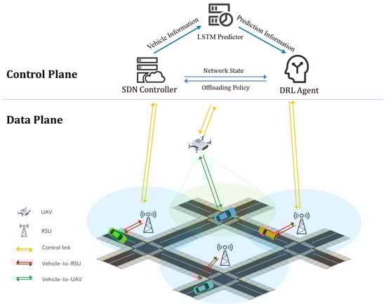
Figure 1.
UAV-assisted VEC network.
We define the set of roadside units (RSUs) as and the set of vehicles as . For convenience, we combine UAVs and RSUs into a set of edge nodes (ENs) , where represents a UAV. Each edge node is equipped with a computing server and an SDN switch for communicating with the SDN controller.
In the control plane, the SDN controller periodically collects global data, including vehicle coordinates and task information, and synchronously forwards them to the LSTM predictor and DRL agent. The LSTM predictor generates future trajectory predictions of vehicles based on historical trajectory data, which are then transmitted to the DRL agent. The DRL agent integrates the prediction results with the current environmental state, outputs the optimization strategy via the TD3 algorithm, and achieves global coordinated control over UAV trajectory planning and task offloading decisions.
3.2. Communication Model
In the construction of the communication system model, vehicles can offload some computing tasks to edge nodes (ENs). We divide the finite time interval into T equal-length time slots, each with a length of . For ease of analysis, the model uses a three-dimensional Cartesian coordinate system, the position of the roadside unit (RSU) is denoted as , the position of vehicle n at time slot t is denoted as , and the position of the UAV at time slot t is denoted as , where H is the fixed flight altitude of the UAV. The flight direction of the UAV is determined by the angle , and the flight speed is . Therefore, the position update of the UAV can be expressed as follows:
Here, is the length of the time slot and T is the set of time slots.
For air-to-ground communication between UAV and vehicles, we adopt a probabilistic path loss model considering line-of-dight (LoS) and non-line-of-sight (NLoS) links [39]. The path loss between the UAV and vehicle n can be expressed as follows:
where f is the carrier frequency, C is the speed of light, and and are the average additional path losses for LoS and NLoS links, respectively. is the LoS link probability, a and b are environment parameters, and is the elevation angle between the UAV and vehicle n.
For ground-to-ground communication between the RSU and vehicles, we adopt the Rayleigh fading channel model, with path loss expressed as follows:
where is the Rayleigh fading coefficient.
To avoid transmission interference, we adopt the Frequency-Division Multiple Access (FDMA) protocol. Define binary variable , representing the association state between vehicle n and edge node m at time slot t, where indicates that vehicle n is associated with edge node m and transmitting data; otherwise, . Considering system resource limitations, we have the following constraints:
where represents the maximum number of vehicles each edge node can serve.
Additionally, we define as the bandwidth resource proportion allocated by edge node m to vehicle n. For simplicity, assume ; i.e., all vehicles associated with the same edge node equally share bandwidth resources.
According to Shannon’s theorem, the transmission rate between vehicle n and edge node m at time slot t is
where (or ) is the total uplink bandwidth of each RSU (or UAV), is the transmission power of vehicle n, is the average power of Additive White Gaussian Noise (AWGN), is the AWGN spectral density, and is the channel gain, where (when ) or (when ).
3.3. Computing Model
In this system, we adopt a partial offloading strategy, allowing vehicles to allocate tasks in arbitrary proportions among local, RSU, or UAV processing. At time slot t, vehicle n randomly generates computational task , with the task arrival rate following a Poisson distribution with parameter . Specifically, , where (unit: bits) represents input data size and (unit: seconds) represents the task’s maximum tolerable delay. Define as the computational offloading proportion of vehicle n at time slot t; i.e., vehicle n offloads an portion of the task to the associated edge node m for remote computation, with the remaining portion executed locally. To cache local computation tasks and edge node offloading tasks, we define task computation queues and for vehicle and edge node , respectively. The evolution of these queues across time slots is as follows:
where and , respectively, represent the amount of data (unit: bits) that vehicle n and edge node m can process at time slot t. represents the local computing capability of vehicle n (unit: CPU cycles/second), (or ) represents the computing capability of the RSU (or UAV) (unit: CPU cycles/second), and represents the number of CPU cycles required to process 1 bit of data.
Based on the above model [40], we calculate service delay and energy consumption for local computation and computational offloading, respectively.
- Local Computation: For the local computation proportion of task , local service delay includes queue waiting time and computation time:whereIn accordance with the commonly adopted power consumption model , where is the effective capacitance coefficient related to the processor chip architecture and is typically set to 3, the local computation energy consumption of vehicle n at time slot t is
- Computational Offloading: If , then the portion of task will be offloaded to edge node m. The offloading service delay is the sum of transmission time, queue waiting time, and computation time:whereSince the data volume of computation results returned by edge nodes is typically much smaller than that of the original task data, we ignore the result return time. Correspondingly, the offloading energy consumption of vehicle n is mainly transmission energy consumption:
In summary the total energy consumption required for the computing task is the sum of the local computing energy consumption and the computing offloading energy consumption, i.e.,
3.4. UAV Energy Consumption Model
- UAV Computation Energy Consumption: Similarly to the vehicle computing energy consumption model, the computing energy consumption of UAV in time slot t is
- Propulsion Energy Consumption: According to the study [41], the flight energy consumption of rotary-wing UAVs is related to their flight speed, expressed as follows:where represents UAV speed, and are the blade profile power and induced power in hovering state, respectively, is rotor blade tip speed, is average rotor-induced speed in hovering state, is the fuselage drag ratio, is air density, is rotor solidity, and is rotor disc area. When the UAV hovers (i.e., flight speed is 0), the hovering energy consumption is .
In summary, the total energy consumption of UAV at time slot t is
3.5. AoI Model
AoI is a destination node-centric metric used to measure information freshness in networks [42]. In this system, we define the AoI of vehicle n at time slot t as , representing the time difference between current time t and the generation time of the most recent computation result received by vehicle n:
where represents the generation time of the most recent computation result received by vehicle n before time slot t. As shown in Figure 2, for vehicle n under the FCFS principle, its AoI accumulates linearly over time until a task computation completes and returns results, at which point AoI drops to the processing delay value of that task. We define the generation time of task u as , computation completion time as , execution time as , and inter-task generation interval as .
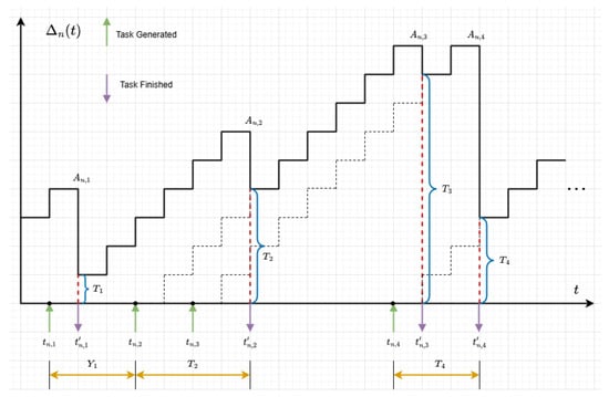
Figure 2.
AoI evolution in UAV-assisted VEC.The dashed lines in the figure represent the reference trajectory of the cumulative task state in the ideal process, used to compare the differences between the actual task processing progress and the theoretical expectations.
We use Peak AoI (PAoI) as the performance metric [43], i.e., the maximum AoI value before the vehicle receives computation results. The PAoI for task u is expressed as follows:
For the partial offloading scheme, the total execution delay of task u is the maximum of local computation and offloading computation delays:
Assuming , the PAoI of vehicle n can be expressed as follows:
where represents the task generation interval of vehicle n. Based on the above system model, we will construct an LSTM prediction-based TD3 optimization framework in the next section, aiming to achieve joint optimization of AoI, energy consumption, and resource rental costs by predicting future vehicle trajectories and task demands.
3.6. Total Cost Function
The total system cost is determined by the AoI cost, energy consumption cost, and computing resource rental cost. We also need to consider the rental price of EN servers. The unit price of computing resources rented by the RSU and UAV (in pennies per CPU cycle) is expressed as or . Therefore, the total price paid by vehicle n to EN m is
All factors affecting the total cost of the system have been calculated, and the total cost can be expressed as
where , , and represent the weight coefficients of AoI cost, energy consumption, and rental price, respectively, and .
Our goal is to optimize UAV trajectories, user associations, and offloading assignments to minimize the long-term costs of N vehicles. We define two sets and . Then, the total cost minimization problem can be formulated as
Since is a set of discrete variables and there is a non-functional in the objective function, it is difficult to obtain the optimal solution of Formula (30) using traditional methods. Therefore, we choose the DRL method to solve this problem.
4. LSTM Prediction-Based TD3 Computing Offloading Optimization Framework
This section introduces in detail our proposed TD3 computation offloading optimization framework based on LSTM trajectory prediction, which achieves forward-looking resource optimization by predicting the future trajectory of the vehicle and effectively solves the decision lag problem in the UAV-assisted VEC network.
4.1. MDP Formulation
In this network model, the dynamic evolution of vehicle and edge node (EN) buffer queues, the continuity of UAV flight trajectories, the time-varying channel gain, the real-time vehicle positions, and the execution of computing tasks in each time slot all exhibit Markovian properties. Meanwhile, the environment’s constant dynamics make it challenging to derive state transition probabilities, thus justifying the use of a model-free MDP [44]. The model-free MDP usually consists of a 3-tuple , where S represents the system state space, A represents the action space, and R represents the reward function.
Specifically, the operation process of the system is as follows: At any time slot t, the SDN controller collects global information and sends it to the DRL agent, and the current environment state is represented as . The agent selects an action from A according to the strategy , interacts with the environment, and immediately obtains a reward of . Then, the environment state transitions to the next state . Based on the rewards obtained, the agent continuously improves its strategy and iteratively learns through continuous interaction with the environment until the optimal strategy is obtained.
4.1.1. State Space S
At the beginning of each time slot, the SDN controller captures the key parameters and global status information of the network environment in real time and transmits these data to the intelligent agent after integration. At this time, the time slot t can be defined as follows:
where , , , , , and are defined as follows.
- is the set of position coordinates of all vehicles and UAVs at time slot t. The heights of vehicles and UAVs remain unchanged, so only their horizontal coordinates need to be considered. The vector dimension is .
- represents the task information of all vehicles at time slot t, including the current task size of each vehicle and the maximum tolerable delay in completing the task. The vector dimension is .
- represents the task generation interval of all vehicles at time slot t, reflecting the time since each vehicle last generated a task. The vector dimension is N.
- represents the queue backlog status at time slot t, including the local queues, RSU queues, and UAV queues of all vehicles. The vector dimension is .
- describes the channel state information at time slot t, including the channel gain between the vehicle and the UAV and RSU. The vector dimension is .
- represents the remaining energy of the UAV at time slot t. Its update follows
4.1.2. Action Space A
The action space consists of two parts: UAV trajectory control and vehicle unloading decision:
- UAV trajectory : As mentioned earlier, the trajectory control of the UAV is determined by the speed and heading angle, i.e., .
- User Association : The user-related variables required for calculation in the system model are discrete variables and cannot be directly output from the action space. Therefore, we designed a mapping method that outputs continuous variables in the action space and maps them to through Equation (32).Here, the indicator function takes the value of 1 when the condition is met; otherwise it is 0. The introduction of the transition variable not only ensures the continuity of the action space of the deep reinforcement learning algorithm, but also satisfies the constraint that each vehicle can only be associated with one EN in a single time slot. Specifically, the following hold:
- When falls within the interval , it means that the vehicle chooses to perform the computing task locally, and all values of , are 0;
- When is in the interval , it means that the vehicle decides to offload the task to the RSU m on its road for processing, corresponding to and ;
- When is in the interval , it means that the vehicle chooses to offload the task to the UAV for processing, and the corresponding and .
- Task Offloading Decision : To reduce the dimension of the action space, the task offloading decision is mapped and coupled with the user association decision. Given that the offloading allocation variable is divided into three intervals, by constructing the mapping relationship , the offloading ratio can be continuously taken in the interval [0,1]. We defineTherefore, the action space only contains the trajectory control variables of the UAV and the user-related variables used to determine the unloading destination and unloading ratio, which are expressed as
User association mapping in Formula (32): This design aims to solve the adaptation problem of the DRL continuous action space and discrete association constraints. By mapping the continuous variable to the “local/RSU/UAV” association state in segments, the continuity of the action space is guaranteed (meeting the requirements of the TD3 algorithm), and the unique user–node association is naturally realized through the constraint of .
4.1.3. Reward Function R
With the aim of minimizing the total system cost, we define a reward function that is negatively associated with the cost function and add three penalty terms, defined as
where
where , , > 0 is a constant that defines the penalty amount. is the user association constraint penalty, which is the penalty when the vehicle exceeds all service ranges; is the delay constraint penalty, which is the penalty when the delay in task processing exceeds the maximum acceptable limit; is the UAV energy constraint penalty, which is the penalty when the UAV has insufficient energy.
The objective of an MDP is to derive an optimal policy for maximizing the expected long-term discounted cumulative reward, i.e.,
where represents the expected value after following the strategy . The discount factor is used to measure the impact of future rewards on the current state. When is close to 0, the agent focuses on immediate benefits and ignores possible future rewards; when is close to 1, the agent will regard long-term benefits and short-term benefits as equally important, and fully consider the long-term impact of decisions.
Therefore, we can solve the problem in Formula (30) using the algorithm based on DRL we proposed. OP1 can be transformed into
4.2. LSTM-TD3
This section details the TD3-based computation offloading optimization framework we proposed, which integrates LSTM trajectory prediction. The framework achieves proactive resource optimization by forecasting vehicle future trajectories, effectively addressing the decision-making lag issue in UAV-assisted VEC networks.
As depicted in Figure 3, the proposed LSTM-TD3 framework consists of four core components: a vehicle trajectory predictor, state processor, TD3 optimizer, and decision fusion mechanism. In contrast to traditional reinforcement learning methods that rely solely on the current state for decision-making, our framework realizes prediction-driven decision optimization through a prediction–decision dual closed-loop mechanism, alongside spatiotemporal correlation perception, proactive state optimization, and prediction quality adaptation.
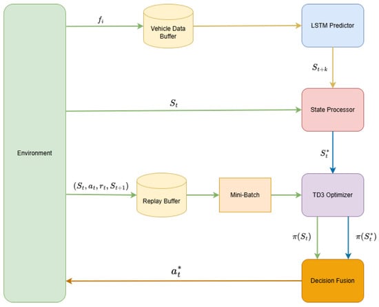
Figure 3.
LSTM-TD3 framework.
4.2.1. Vehicle Trajectory Predictor
The trajectory prediction network we designed adopts an encoder–decoder architecture to improve sequence modeling capabilities. The network can capture both short-term and long-term dependencies of vehicle trajectories. The prediction network mainly consists of a feature encoding layer, a multi-layer LSTM encoder, a self-attention mechanism, and a prediction decoder. For the input sequence , where is the d-dimensional eigenvector at time t.
The prediction process can be described as follows: First, the input sequence is normalized and dimensionally transformed:
Then the multi-layer LSTM processes the encoded sequence:
Then the self-attention mechanism is applied to capture the long-distance dependencies within the sequence; finally, the LSTM output and the attention context vector are combined for prediction:
To fully capture the kinematics and task characteristics of the vehicle, we extract a six-dimensional feature vector for each vehicle:
where represents the position coordinates of the vehicle in the two-dimensional plane, is the vehicle speed, is the driving direction, is the current task data size, and is the task generation rate.
4.2.2. State Processor
The core innovation of the LSTM-TD3 framework is to fuse the predicted future state with the current observed state to achieve forward-looking decision-making. The state processor is responsible for implementing the following fusion process:
where is the current state after smoothing, is the state at time predicted based on the information at time t, is the prediction confidence, and is the fusion function. The fusion function we designed adopts the weighted average form
This formula dynamically adjusts the weights of the current state and the predicted state according to the prediction confidence . When the prediction quality is high, the system is more inclined to trust the predicted state and achieve forward-looking decision-making; when the prediction quality is low, the system relies more on the current observation state to maintain robustness.
State fusion dynamically balances the weights of the current state and the predicted state via prediction confidence , with its core focus on addressing the question of “how prediction errors influence state inputs”. When prediction errors are high, the weight assigned to the predicted state is automatically reduced to mitigate its interference with decision-making. This ensures more robust foundational information for subsequent optimization processes and avoids decision biases that might arise from over-reliance on either predictions alone or the current state in isolation.
4.2.3. TD3 Optimizer
The TD3 algorithm is an advanced deep reinforcement learning method designed for continuous action spaces. The target value calculation formula for TD3 is as follows:
where is the truncated Gaussian noise and and are the parameters of the target critic network and the target actor network, respectively.
Different from the standard TD3, we further introduce the prediction enhancement feature and modify the target value calculation:
where is the fused state generated by the state processor, which contains prediction information. This modification enables the optimizer to consider future state changes and achieve forward-looking decision-making.
4.2.4. Decision Fusion
The decision fusion mechanism is a key innovative component of the LSTM-TD3 framework, which organically integrates trajectory prediction, state processing, and optimization decision-making to achieve prediction-driven adaptive resource allocation.
Mathematically, the entire fusion process can be expressed as follows:
where is the current observed state, is the predicted state for the next k moments, is the policy output based on the current state, is the policy output based on the fusion state, is the prediction confidence, is the historical knowledge base, and is the decision fusion function.
The core of the decision fusion mechanism is to dynamically adjust the weights of the current decision and the prediction-guided decision according to the prediction quality. We design an adaptive weighted fusion model:
where is the fusion weight, which is determined by the prediction confidence and the environment dynamics :
is the modulation function of the environment dynamics:
is the threshold parameter, and controls the function steepness. When the environment is highly dynamic, is close to 1, and the system is more inclined to believe in prediction-guided decisions; when the environment is relatively static, is close to 0, and the system is more inclined to the current optimal decision. The dynamics of the environment is quantified by indicators such as vehicle speed, queue change rate, and channel state change rate. The prediction confidence is calculated by evaluating the historical prediction error:
where is the historical prediction error, is the scaling factor, and w is the window size.
Decision fusion is based on prediction confidence and environmental dynamics to adjust weights , focusing on solving the problem of “how to adapt to the dynamic needs of the scene”. High-dynamic scenes increase the weight of prediction-oriented decisions to respond in advance, while low-dynamic scenes focus on current state decisions to reduce redundant adjustments, achieving accurate adaptation of decision strategies in different scenarios.
4.2.5. Framework Process
At the beginning of each episode, the system randomly initializes the environment, including the initial positions of vehicles and UAVs, the backlog status of task queues for vehicles and edge nodes (ENs), the remaining energy of UAVs, and wireless channel conditions. Subsequently, the core components of the algorithm are initialized to construct a complete prediction and decision framework. Meanwhile, an experience replay buffer is developed to retain experience triples (, , r, ) of the agent’s interaction with the environment; a vehicle data buffer is created to store the time series of vehicle motion and task characteristics .
At each time step t, the system first collects the global state information st through the SDN controller, including vehicle location, task information, queue status, and channel conditions. The vehicle trajectory predictor extracts the historical sequence from the vehicle data buffer and uses a multi-layer LSTM encoder and self-attention mechanism to predict the vehicle state in the next k steps.
As the core fusion component, the state processor dynamically calculates the fusion weight based on the prediction confidence and performs weighted fusion on the current observed state st and the predicted state to generate the enhanced state , where is the current state after smoothing.
The TD3 optimizer generates an action at based on the enhanced state through the actor network, including UAV trajectory control and task offloading decisions. After the system executes the action, it obtains the reward rt and the next state st+1. The experience quadruple is stored in the playback buffer for TD3 network training, and the vehicle feature data is stored in a dedicated buffer for LSTM prediction network learning.
As the final decision-making component, the decision fusion device calculates the adaptive fusion weight according to the prediction confidence and the environment dynamics , performs weighted fusion of the current optimal strategy and the forward-looking strategy , and outputs the final execution action . This two-layer fusion mechanism not only ensures the effective use of prediction information but also ensures the robustness of decision-making through adaptive weight adjustment, realizing true prediction-driven adaptive resource allocation. Algorithm 1 shows the detailed workflow of LSTM-TD3.
| Algorithm 1: LSTM prediction-based TD3 computation offloading optimization |
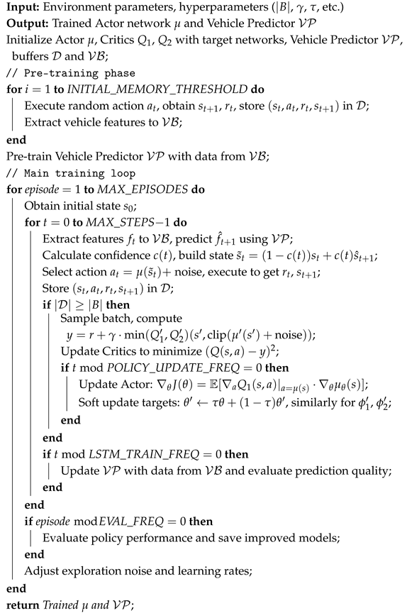 |
5. Experiments
In this section, we substantiate the effectiveness of the LSTM-TD3 framework in UAV-assisted VEC network resource optimization through extensive simulation experiments. We first introduce the simulation environment setup and benchmark method and then analyze the performance advantages of our method in detail from multiple aspects.
5.1. Simulation Parameter Settings
To validate the proposed method, we constructed an end-to-end simulation platform using Python 3.12.1 and PyTorch 2.6.0 and conducted simulation experiments on a computer equipped with an Intel i7-14650K CPU(Intel Corporation, Santa Clara, CA, USA) and an NVIDIA RTX 4060 GPU(NVIDIA Corporation, Santa Clara, CA, USA). In the proposed LSTM-TD3 framework, the LSTM prediction network employs an encoder–decoder architecture, comprising two layers of LSTM networks with a hidden dimension of 64 for each layer. The input to the network is a historical trajectory sequence of vehicles with a length of 4, where the feature vector at each time step has six dimensions, including vehicle position, speed, direction, task size, and task interval information. The network incorporates a self-attention mechanism to capture long-range temporal dependencies, and its output is the vehicle state prediction for the next two time steps. For the TD3 network configuration, it consists of an actor network and two critic networks; each network contains two fully connected hidden layers with 600 and 400 neurons, respectively. The hidden layers utilize the ReLU activation function, while the output layer of the actor network adopts the Tanh function to constrain the action values within the range of . The specific configurations of key hyperparameters are presented in Table 1.

Table 1.
Hyperparameters of LSTM predictor and TD3 optimizer.
In order to verify that the algorithm can be used in a variety of scenarios, we set up two common scenarios, as shown in Figure 4. Map 1 is a 1000 m straight road with two RSUs evenly arranged on both sides of the road, and each RSU covers an area of 100 m. Map 2 is an area consisting of a 1000 m east–west lane and a 400 m north–south lane, with three RSUs deployed at (150, 100), (500, 300), and (850, 100). All vehicles are uniformly distributed along the road and travel in random directions with a predefined speed. The time slot length is 0.05 s, and at the commencement of each time slot, the vehicle randomly generates tasks according to the Poisson distribution, and the task arrival rate is . The network environment parameters of UAV-assisted VEC are shown in Table 2.
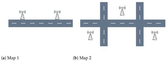
Figure 4.
Simulated scenarios.
Table 2.
Environment parameters of UAV-assisted VEC.
5.2. System Convergence
To verify the convergence of the proposed algorithm, we set the number of vehicles to 10, 30, and 50, respectively, and simulated the system’s convergence performance under sparse, normal, and congested conditions. For comparison, the TD3 algorithm was tested with 30 vehicles, and the results are presented in Figure 5.
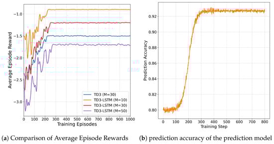
Figure 5.
Simulated scenarios.
We configured the training process with 1000 episodes, where each episode consists of 100 steps. As shown in Figure 5a, the average episode reward exhibits significant fluctuations around a low value in the initial stage of training. This is because the agent lacks sufficient environmental knowledge and relies on random actions for decision-making. With the progression of training, after accumulating an adequate amount of data samples, the reward increases rapidly. By approximately 200 episodes, the DRL network can achieve high and stable reward values. Additionally, as the number of vehicles N increases, the system cost rises accordingly, but the convergence speed remains largely unaffected.
It is worth noting that the performance fluctuation of LSTM-TD3 in the early stage of training (the first 200 rounds) is greater than that of TD3. This is because the prediction model has not fully converged, and the resulting prediction errors can lead to unstable decisions. With further training of the prediction model, this fluctuation will be significantly reduced, and stable high performance will eventually be achieved. The prediction accuracy of the prediction model is shown in Figure 5b.
As shown in Figure 6, we explored the impact of different learning rates on the performance of the LSTM-TD3 algorithm. In the experiment, parameters , , and were each set within the range of 0.0001 to 0.01, and various combinations of these parameters were tested. The results indicate that when the learning rates are too high, the training process becomes unstable. Conversely, when the learning rates are too low, not only does the convergence speed of training significantly slow down, but it also tends to get trapped in local optimal solutions. The experimental data shows that the algorithm achieves optimal performance when , , and . Therefore, in subsequent experiments, we will adopt this set of learning rate parameters for related research.
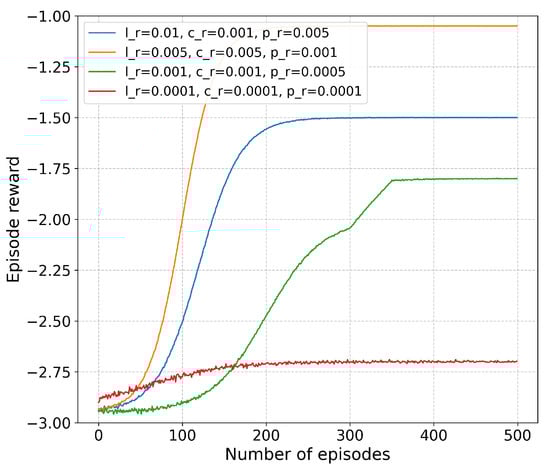
Figure 6.
Vehicle prediction rate.
5.3. Performance Evaluation
To comprehensively evaluate the performance advantage of our approach, we select the following methods as baselines:
- TD3: Standard TD3 algorithm without prediction mechanism, making decisions based only on the current observation state.
- DDPG: Deterministic Policy Gradient algorithm using a single critic network.
- LE (Local Execution): All tasks are performed locally.
- FO (Full Offloading): All tasks are completely offloaded to the RSU for execution.
- RO (Random Offloading): Computation tasks are randomly selected and executed locally, offloaded to RSUs or UAVs.
First, we conduct experiments on the two maps shown in Figure 4, where the number of vehicles N = 30. Figure 7 illustrates the experimental results. The system cost of the proposed LSTM-TD3 algorithm consistently remains lower than that of other strategies in both experimental scenarios, demonstrating the versatility and superiority of the LSTM-TD3 algorithm. In Map 1, the FO strategy incurs significantly higher costs than other approaches. The primary reason is that the insufficient number of RSUs fails to support the full offloading requirement of FO, leading to a rise in AoI and a surge in system costs. To facilitate the investigation of other indicators’ impact on the algorithm, subsequent experiments are conducted on MAP2.
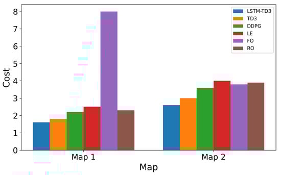
Figure 7.
The cost of using different strategies and maps.
To deeply analyze the impact of prediction accuracy on system performance, we designed a series of comparative experiments, and the results are shown in Figure 8. We compared three cases: (1) accurate prediction, using the real future state; (2) LSTM prediction, using our prediction model; and (3) no prediction, using only the current state.
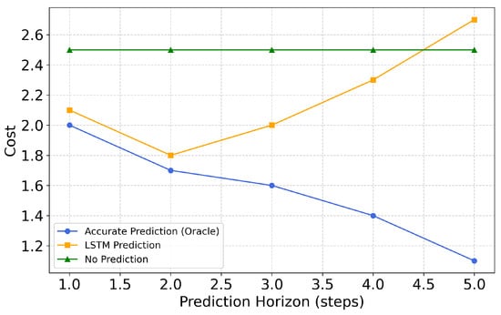
Figure 8.
Effect of prediction step size on cost.
The experimental results indicate that as the prediction horizon increases, system performance first improves and then declines. For the LSTM-TD3 framework, the optimal prediction horizon is two steps (equivalent to approximately 16 s), at which point the maximum performance improvement is achieved; beyond three steps, performance begins to decrease. This phenomenon arises because the accumulation of prediction errors over longer horizons leads to performance degradation. While the performance advantages of accurate predictions continue to grow with an extended prediction horizon—validating the theoretical value of forward-looking decision-making—in practical systems, prediction errors restrict the realization of this potential. These findings demonstrate that the quality of the prediction model is a critical factor influencing system performance, thereby confirming the necessity of incorporating prediction quality evaluation and adaptive fusion mechanisms.
We verified the performance of each algorithm under different strategies, as shown in Figure 9. First, we constructed four strategies: normal ( = 0.33, = 0.33, and = 0.33), Time-sensitive ( = 0.8, = 0.1, and = 0.1), energy-deficiency ( = 0.1, = 0.8, and = 0.1), and fund-poor ( = 0.1, = 0.1, and = 0.8). The experiment showed that in time-sensitive and energy-constrained scenarios, the performance of the LSTM-TD3 algorithm was significantly better than that of the TD3 algorithm. This is due to the forward-looking nature of the LSTM-TD3 algorithm, which can deploy drones in advance and plan the optimal path.
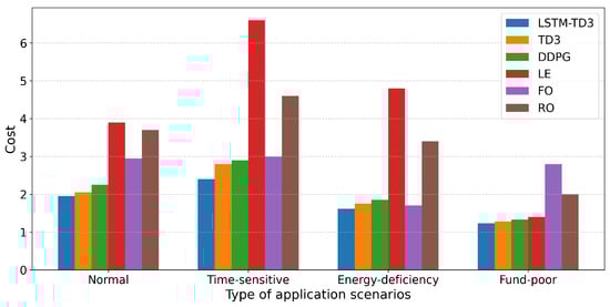
Figure 9.
Costs of different strategies and tasks.
Figure 10 shows the performance comparison of each algorithm under different numbers of vehicles. The experimental range is from 5 vehicles to 50 vehicles to evaluate the adaptability of the system under different loads. The experimental results show that the total cost of each method increases with the number of vehicles, but the increase is different. Among them, the cost of LSTM-TD3 increases most slowly, reflecting its better scalability in high-load scenarios. When the number of vehicles is 30, the performance advantage of LSTM-TD3 over the original TD3 can reach up to 28.9%, indicating that prediction-driven decision-making is more significant in medium- and high-load scenarios. In low-load scenarios (10 vehicles), due to weak resource competition, the performance differences of each algorithm are small, and a simple strategy can achieve good results. In addition, as the number of vehicles increases, the performance of the LE strategy drops sharply, further verifying the necessity of computational offloading in high-load environments.
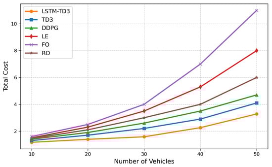
Figure 10.
Impact of the number of vehicles on costs.
We study the impact of different task generation rates on system performance by adjusting the parameter of the Poisson process, and the results are shown in Figure 11. The results show that the total cost of all methods increases significantly with the increase in task generation rate, but LSTM-TD3 increases the slowest. When = 0.8, the average AoI of LSTM-TD3 is 24.9% lower than that of the original TD3. At medium and low task generation rates, the performance gap between LSTM-TD3 and TD3 is relatively small. However, as the task generation rate increases, the advantage of prediction-driven LSTM-TD3 becomes more obvious, which proves the importance of forward-looking decision-making in highly dynamic environments. The cost of the FO strategy rises sharply due to the increase in the number of tasks.
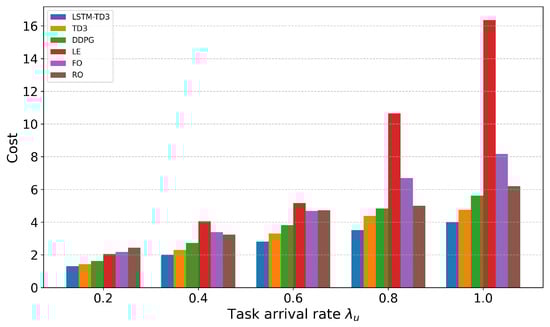
Figure 11.
Impact of task arrival rate on cost.
To evaluate the system’s adaptability to varying task sizes, we adjusted the task size range and observed system performance, as depicted in Figure 12. In the experiment, task sizes ranged from 0.5 MB to 4 MB. The results indicate that energy consumption and total costs for all methods increase significantly as task size grows. LSTM-TD3 demonstrates optimal performance across all task sizes, particularly in large-task scenarios. In such scenarios, LSTM-TD3 achieves the most substantial energy consumption advantage, reducing it by 21.7% compared to the original TD3. This is because the prediction mechanism allows the UAV to proactively relocate to vehicle-dense areas, thereby shortening transmission distances and lowering energy consumption.
Figure 12.
Impact of average data size on cost.
Figure 13 illustrates an example demonstrating the forward-looking decision-making advantage of LSTM-TD3 in a specific scenario. Here, three vehicles are traveling at high speed from left to right and are on the verge of entering an RSU coverage blind spot. LSTM-TD3 anticipates this situation in advance, directing the UAV to relocate to the blind spot proactively for service preparation. In contrast, the original TD3 only moves the UAV after the vehicles have actually entered the blind spot, leading to evident decision latency.
Figure 13.
Comparison of LSTM-TD3 and TD3 trajectories. The arrow indicates that the car and the drone start to move at this moment.
This case intuitively demonstrates the core advantage of prediction-driven decision-making: it enables proactive adjustment of resource allocation based on future state predictions, thereby avoiding service quality degradation caused by reactive responses.
Integrating all experimental findings, our LSTM-TD3 framework exhibits significant performance advantages across diverse network conditions, particularly in highly dynamic environments and high-load scenarios. The prediction-driven forward-looking decision-making approach has pioneered a new research direction for resource optimization in UAV-assisted VEC networks.
6. Conclusions
In this paper, we propose a TD3 deep reinforcement learning framework integrated with LSTM-based trajectory prediction to address the resource optimization problem in the UAV-assisted Internet of Vehicles (IoV) edge computing environment. By predicting the future trajectories and task requirements of vehicles, this framework enables forward-looking resource allocation, effectively mitigating the decision lag issue in highly dynamic environments. The primary contributions of this study are outlined as follows: First, we developed a software-defined network (SDN)-driven UAV-assisted vehicular edge computing system model, covering communication, computing, energy consumption, and information timeliness models. This provides a comprehensive theoretical foundation for resource optimization. Second, for the first time, we organically integrated LSTM-based trajectory prediction with the TD3 reinforcement learning algorithm, designing a four-module framework comprising a vehicle trajectory predictor, state processor, TD3 optimizer, and decision fusion mechanism. Through a prediction–decision dual closed-loop mechanism, this framework realizes perception and optimization of future states, significantly enhancing the system’s adaptability to environmental changes. Third, we developed state smoothing and data augmentation techniques to enhance training stability and proposed a multi-objective optimization model integrating Age of Information (AoI), energy consumption, and resource rental costs, thereby comprehensively considering all aspects of system performance. Finally, through extensive experimental validations across diverse network scenarios, our LSTM-TD3 method outperforms existing approaches significantly in terms of total system cost, information freshness, and environmental adaptability. Notably, the advantages of prediction-driven decision-making are more pronounced in high-load and highly dynamic environments. When the number of vehicles , the performance of LSTM-TD3 is improved by up to 24.9% compared with the original TD3; under high task generation rates, the average AoI is reduced by 31.5%; and in large-scale task scenarios, energy consumption is reduced by 21.7%.
In future work, we will focus on advancing research in several key directions: On the one hand, we plan to incorporate more sophisticated probabilistic modeling techniques and Bayesian reasoning frameworks, systematically exploring uncertainty quantification methods to overcome the limitations of existing prediction steps and accuracy. Simultaneously, by developing a system model more aligned with real-world scenarios (e.g., incorporating practical factors such as extreme weather and complex road networks), we will further enhance the system’s robustness in dynamic environments. On the other hand, multi-UAV collaboration mechanisms will be the core breakthrough, focusing on addressing issues of collaborative trajectory planning, load balancing, and interference management in large-scale complex scenarios to build a collaborative system adaptable to highly dynamic environments. Additionally, security research is equally essential; we plan to leverage adversarial network techniques to strengthen the system’s capability to resist malicious interference and abnormal data, ensuring the stable operation of critical applications. Finally, we will also prioritize advancing the lightweight design of models and the development of efficient architectures, reducing computational overhead via techniques such as neural network pruning and knowledge distillation, improving real-time response capabilities in resource-constrained scenarios, and facilitating the framework’s transition to practical deployment.
Author Contributions
Conceptualization: J.X. and H.H.; Methods: J.X.; Software: J.X.; Validation: J.X. and H.H.; Formal Analysis: J.X.; Investigation: J.X.; Resources: J.X.; Data Curation: J.X.; Writing—Original Draft: J.X.; Writing—Review and Editing: H.H.; Visualization: J.X.; Supervision: H.H.; Project Administration: J.X. All authors have read and agreed to the published version of the manuscript.
Funding
This research was funded by the National Natural Science Foundation of China (NSFC) via grant 62401304, 62225105; project ZR2022QF040 supported by Shandong Provincial Natural Science Foundation; and the QLU Talent Research Project under grant 2023RCKY138; The Young Talent of Lifting Engineering for Science and Technology in Shandong, China via SDAST2025QTA077.
Institutional Review Board Statement
Not applicable.
Informed Consent Statement
Not applicable.
Data Availability Statement
In this study, the data used were randomly generated by a custom simulation environment based on Python, including vehicle dynamic states, task parameters, etc. The data are simulated and do not involve real samples. They were randomly generated through a probability model, and a fixed seed was adopted to ensure reproducibility.
Conflicts of Interest
The authors declare no conflicts of interest.
References
- Alalwany, E.; Mahgoub, I. Security and trust management in the internet of vehicles (IoV): Challenges and machine learning solutions. Sensors 2024, 24, 368. [Google Scholar] [CrossRef]
- Dong, S.; Tang, J.; Abbas, K.; Hou, R.; Kamruzzaman, J.; Rutkowski, L.; Buyya, R. Task offloading strategies for mobile edge computing: A survey. Comput. Netw. 2024, 254, 110791. [Google Scholar] [CrossRef]
- Fan, W.; Zhang, Y.; Zhou, G.; Liu, Y. Deep reinforcement learning-based task offloading for vehicular edge computing with flexible RSU-RSU cooperation. IEEE Trans. Intell. Transp. Syst. 2024, 25, 7712–7725. [Google Scholar] [CrossRef]
- Ahmed, M.; Raza, S.; Soofi, A.A.; Khan, F.; Khan, W.U.; Xu, F.; Chatzinotas, S.; Dobre, O.A.; Han, Z. A survey on reconfigurable intelligent surfaces assisted multi-access edge computing networks: State of the art and future challenges. Comput. Sci. Rev. 2024, 54, 100668. [Google Scholar] [CrossRef]
- Sun, W.; Wang, P.; Xu, N.; Wang, G.; Zhang, Y. Dynamic Digital Twin and Distributed Incentives for Resource Allocation in Aerial-Assisted Internet of Vehicles. IEEE Internet Things J. 2022, 9, 5839–5852. [Google Scholar] [CrossRef]
- Yu, J.; Wu, J.; Jiang, H. Spatio-Temporal Trajectory Design for UAVs: Enhancing URLLC and LoS Transmission in Communications. IEEE Wirel. Commun. Lett. 2024, 13, 2417–2421. [Google Scholar] [CrossRef]
- Javed, S.; Hassan, A.; Ahmad, R.; Ahmed, W.; Ahmed, R.; Saadat, A.; Guizani, M. State-of-the-art and future research challenges in uav swarms. IEEE Internet Things J. 2024, 11, 19023–19045. [Google Scholar] [CrossRef]
- Li, C.; Zhang, Y.; Yu, L.; Yang, M. Efficient Vehicle Selection and Resource Allocation for Knowledge Distillation-Based Federated Learning in UAV-Assisted VEC. IEEE Trans. Intell. Transp. Syst. 2025, 26, 6321–6331. [Google Scholar] [CrossRef]
- Jin, H.; Jin, X.; Zhou, Y.; Guo, P.; Ren, J.; Yao, J.; Zhang, S. A survey of energy efficient methods for UAV communication. Veh. Commun. 2023, 41, 100594. [Google Scholar] [CrossRef]
- Yi, M.; Lee, V.C.; Yang, P.; Li, P.; Zhang, Y.; Wei, W.; Gao, H. The Distributed Intelligent Collaboration to UAV-Assisted VEC: Joint Position Optimization and Task Scheduling. IEEE Internet Things J. 2025, 12, 21473–21487. [Google Scholar] [CrossRef]
- Wu, Q.; Cui, M.; Zhang, G.; Wang, F.; Wu, Q.; Chu, X. Latency Minimization for UAV-Enabled URLLC-Based Mobile Edge Computing Systems. IEEE Trans. Wirel. Commun. 2024, 23, 3298–3311. [Google Scholar] [CrossRef]
- Zhan, C.; Lai, H. Energy Minimization in Internet-of-Things System Based on Rotary-Wing UAV. IEEE Wirel. Commun. Lett. 2019, 8, 1341–1344. [Google Scholar] [CrossRef]
- Zhang, K.; Gui, X.; Ren, D.; Li, D. Energy–Latency Tradeoff for Computation Offloading in UAV-Assisted Multiaccess Edge Computing System. IEEE Internet Things J. 2021, 8, 6709–6719. [Google Scholar] [CrossRef]
- Pervez, F.; Sultana, A.; Yang, C.; Zhao, L. Energy and Latency Efficient Joint Communication and Computation Optimization in a Multi-UAV-Assisted MEC Network. IEEE Trans. Wirel. Commun. 2024, 23, 1728–1741. [Google Scholar] [CrossRef]
- Yang, Y.; Song, T.; Yang, J.; Xu, H.; Xing, S. Joint Energy and AoI Optimization in UAV-Assisted MEC-WET Systems. IEEE Sens. J. 2024, 24, 15110–15124. [Google Scholar] [CrossRef]
- Yan, J.; Zhao, X.; Li, Z. Deep-Reinforcement-Learning-Based Computation Offloading in UAV-Assisted Vehicular Edge Computing Networks. IEEE Internet Things J. 2024, 11, 19882–19897. [Google Scholar] [CrossRef]
- Liu, L.; Chen, C.; Pei, Q.; Maharjan, S.; Zhang, Y. Vehicular edge computing and networking: A survey. Mob. Netw. Appl. 2021, 26, 1145–1168. [Google Scholar] [CrossRef]
- Wang, M.; Yi, H.; Jiang, F.; Lin, L.; Gao, M. Review on offloading of vehicle edge computing. J. Artif. Intell. Technol. 2022, 2, 132–143. [Google Scholar] [CrossRef]
- Liu, K.; Xu, X.; Chen, M.; Liu, B.; Wu, L.; Lee, V.C.S. A Hierarchical Architecture for the Future Internet of Vehicles. IEEE Commun. Mag. 2019, 57, 41–47. [Google Scholar] [CrossRef]
- Huang, X.; He, L.; Chen, X.; Wang, L.; Li, F. Revenue and Energy Efficiency-Driven Delay-Constrained Computing Task Offloading and Resource Allocation in a Vehicular Edge Computing Network: A Deep Reinforcement Learning Approach. IEEE Internet Things J. 2022, 9, 8852–8868. [Google Scholar] [CrossRef]
- Abrar, M.; Ajmal, U.; Almohaimeed, Z.M.; Gui, X.; Akram, R.; Masroor, R. Energy Efficient UAV-Enabled Mobile Edge Computing for IoT Devices: A Review. IEEE Access 2021, 9, 127779–127798. [Google Scholar] [CrossRef]
- Huda, S.A.; Moh, S. Survey on computation offloading in UAV-Enabled mobile edge computing. J. Netw. Comput. Appl. 2022, 201, 103341. [Google Scholar] [CrossRef]
- Wang, C.; Yao, T.; Fan, T.; Peng, S.; Xu, C.; Yu, S. Modeling on Resource Allocation for Age-Sensitive Mobile-Edge Computing Using Federated Multiagent Reinforcement Learning. IEEE Internet Things J. 2024, 11, 3121–3131. [Google Scholar] [CrossRef]
- Wu, W.; Yang, P.; Zhang, W.; Zhou, C.; Shen, X. Accuracy-Guaranteed Collaborative DNN Inference in Industrial IoT via Deep Reinforcement Learning. IEEE Trans. Ind. Inform. 2021, 17, 4988–4998. [Google Scholar] [CrossRef]
- Aizaz Ul Haq, S.; Imran, M.; Shah, N.; Muntean, G.M. SDN-Based Edge Computing in Vehicular Communication Networks: A Survey of Existing Approaches. IEEE Access 2025, 13, 74252–74287. [Google Scholar] [CrossRef]
- Wang, K.; Yin, H.; Quan, W.; Min, G. Enabling Collaborative Edge Computing for Software Defined Vehicular Networks. IEEE Netw. 2018, 32, 112–117. [Google Scholar] [CrossRef]
- Luo, G.; Zhou, H.; Cheng, N.; Yuan, Q.; Li, J.; Yang, F.; Shen, X. Software-Defined Cooperative Data Sharing in Edge Computing Assisted 5G-VANET. IEEE Trans. Mob. Comput. 2021, 20, 1212–1229. [Google Scholar] [CrossRef]
- Ullah, I.; Lim, H.K.; Seok, Y.J.; Han, Y.H. Optimizing task offloading and resource allocation in edge-cloud networks: A DRL approach. J. Cloud Comput. 2023, 12, 112. [Google Scholar] [CrossRef]
- Hao, H.; Xu, C.; Zhang, W.; Yang, S.; Muntean, G.M. Task-Driven Priority-Aware Computation Offloading Using Deep Reinforcement Learning. IEEE Trans. Wirel. Commun. 2025; early eccess. [Google Scholar] [CrossRef]
- Li, B.; Yang, R.; Liu, L.; Wang, J.; Zhang, N.; Dong, M. Robust Computation Offloading and Trajectory Optimization for Multi-UAV-Assisted MEC: A Multiagent DRL Approach. IEEE Internet Things J. 2024, 11, 4775–4786. [Google Scholar] [CrossRef]
- Hao, H.; Xu, C.; Zhang, W.; Yang, S.; Muntean, G.M. Joint Task Offloading, Resource Allocation, and Trajectory Design for Multi-UAV Cooperative Edge Computing With Task Priority. IEEE Trans. Mob. Comput. 2024, 23, 8649–8663. [Google Scholar] [CrossRef]
- Al-Selwi, S.M.; Hassan, M.F.; Abdulkadir, S.J.; Muneer, A.; Sumiea, E.H.; Alqushaibi, A.; Ragab, M.G. RNN-LSTM: From applications to modeling techniques and beyond—Systematic review. J. King Saud Univ.-Comput. Inf. Sci. 2024, 36, 102068. [Google Scholar] [CrossRef]
- Yu, Y.; Si, X.; Hu, C.; Zhang, J. A review of recurrent neural networks: LSTM cells and network architectures. Neural Comput. 2019, 31, 1235–1270. [Google Scholar] [CrossRef]
- Liu, C.; Xiao, Z.; Long, W.; Li, T.; Jiang, H.; Li, K. Vehicle trajectory data processing, analytics, and applications: A survey. ACM Comput. Surv. 2025, 57, 1–36. [Google Scholar] [CrossRef]
- Altché, F.; de La Fortelle, A. An LSTM network for highway trajectory prediction. In Proceedings of the 2017 IEEE 20th International Conference on Intelligent Transportation Systems (ITSC), Yokohama, Japan, 16–19 October2017; pp. 353–359. [Google Scholar]
- Messaoud, K.; Yahiaoui, I.; Verroust-Blondet, A.; Nashashibi, F. Attention based vehicle trajectory prediction. IEEE Trans. Intell. Veh. 2020, 6, 175–185. [Google Scholar] [CrossRef]
- Tu, Y.; Chen, H.; Yan, L.; Zhou, X. Task offloading based on LSTM prediction and deep reinforcement learning for efficient edge computing in IoT. Future Internet 2022, 14, 30. [Google Scholar] [CrossRef]
- Behera, S.R.; Panigrahi, N.; Bhoi, S.K.; Sahoo, K.S.; Jhanjhi, N.; Ghoniem, R.M. Time series-based edge resource prediction and parallel optimal task allocation in mobile edge computing environment. Processes 2023, 11, 1017. [Google Scholar] [CrossRef]
- Al-Hourani, A.; Kandeepan, S.; Lardner, S. Optimal LAP altitude for maximum coverage. IEEE Wirel. Commun. Lett. 2014, 3, 569–572. [Google Scholar] [CrossRef]
- Wang, L.; Wang, K.; Pan, C.; Xu, W.; Aslam, N.; Nallanathan, A. Deep Reinforcement Learning Based Dynamic Trajectory Control for UAV-Assisted Mobile Edge Computing. IEEE Trans. Mob. Comput. 2022, 21, 3536–3550. [Google Scholar] [CrossRef]
- Zeng, Y.; Xu, J.; Zhang, R. Energy Minimization for Wireless Communication With Rotary-Wing UAV. IEEE Trans. Wirel. Commun. 2019, 18, 2329–2345. [Google Scholar] [CrossRef]
- Amodu, O.A.; Jarray, C.; Azlina Raja Mahmood, R.; Althumali, H.; Ali Bukar, U.; Nordin, R.; Abdullah, N.F.; Cong Luong, N. Deep Reinforcement Learning for AoI Minimization in UAV-Aided Data Collection for WSN and IoT Applications: A Survey. IEEE Access 2024, 12, 108000–108040. [Google Scholar] [CrossRef]
- Yates, R.D.; Sun, Y.; Brown, D.R.; Kaul, S.K.; Modiano, E.; Ulukus, S. Age of Information: An Introduction and Survey. IEEE J. Sel. Areas Commun. 2021, 39, 1183–1210. [Google Scholar] [CrossRef]
- Sutton, R.S.; Barto, A.G. Reinforcement learning: An introduction. IEEE Trans. Neural Netw. 1998, 9, 1054. [Google Scholar] [CrossRef]
Disclaimer/Publisher’s Note: The statements, opinions and data contained in all publications are solely those of the individual author(s) and contributor(s) and not of MDPI and/or the editor(s). MDPI and/or the editor(s) disclaim responsibility for any injury to people or property resulting from any ideas, methods, instructions or products referred to in the content. |
© 2025 by the authors. Licensee MDPI, Basel, Switzerland. This article is an open access article distributed under the terms and conditions of the Creative Commons Attribution (CC BY) license (https://creativecommons.org/licenses/by/4.0/).